WO2010143534A1 - 地絡検出器の接続診断装置 - Google Patents
地絡検出器の接続診断装置 Download PDFInfo
- Publication number
- WO2010143534A1 WO2010143534A1 PCT/JP2010/058855 JP2010058855W WO2010143534A1 WO 2010143534 A1 WO2010143534 A1 WO 2010143534A1 JP 2010058855 W JP2010058855 W JP 2010058855W WO 2010143534 A1 WO2010143534 A1 WO 2010143534A1
- Authority
- WO
- WIPO (PCT)
- Prior art keywords
- relay
- connection
- voltage
- ground fault
- diagnosis
- Prior art date
Links
Images

Classifications
-
- B—PERFORMING OPERATIONS; TRANSPORTING
- B60—VEHICLES IN GENERAL
- B60L—PROPULSION OF ELECTRICALLY-PROPELLED VEHICLES; SUPPLYING ELECTRIC POWER FOR AUXILIARY EQUIPMENT OF ELECTRICALLY-PROPELLED VEHICLES; ELECTRODYNAMIC BRAKE SYSTEMS FOR VEHICLES IN GENERAL; MAGNETIC SUSPENSION OR LEVITATION FOR VEHICLES; MONITORING OPERATING VARIABLES OF ELECTRICALLY-PROPELLED VEHICLES; ELECTRIC SAFETY DEVICES FOR ELECTRICALLY-PROPELLED VEHICLES
- B60L3/00—Electric devices on electrically-propelled vehicles for safety purposes; Monitoring operating variables, e.g. speed, deceleration or energy consumption
- B60L3/0023—Detecting, eliminating, remedying or compensating for drive train abnormalities, e.g. failures within the drive train
-
- G—PHYSICS
- G01—MEASURING; TESTING
- G01R—MEASURING ELECTRIC VARIABLES; MEASURING MAGNETIC VARIABLES
- G01R31/00—Arrangements for testing electric properties; Arrangements for locating electric faults; Arrangements for electrical testing characterised by what is being tested not provided for elsewhere
- G01R31/50—Testing of electric apparatus, lines, cables or components for short-circuits, continuity, leakage current or incorrect line connections
- G01R31/66—Testing of connections, e.g. of plugs or non-disconnectable joints
-
- H—ELECTRICITY
- H02—GENERATION; CONVERSION OR DISTRIBUTION OF ELECTRIC POWER
- H02H—EMERGENCY PROTECTIVE CIRCUIT ARRANGEMENTS
- H02H3/00—Emergency protective circuit arrangements for automatic disconnection directly responsive to an undesired change from normal electric working condition with or without subsequent reconnection ; integrated protection
- H02H3/02—Details
- H02H3/04—Details with warning or supervision in addition to disconnection, e.g. for indicating that protective apparatus has functioned
- H02H3/044—Checking correct functioning of protective arrangements, e.g. by simulating a fault
-
- H—ELECTRICITY
- H02—GENERATION; CONVERSION OR DISTRIBUTION OF ELECTRIC POWER
- H02H—EMERGENCY PROTECTIVE CIRCUIT ARRANGEMENTS
- H02H3/00—Emergency protective circuit arrangements for automatic disconnection directly responsive to an undesired change from normal electric working condition with or without subsequent reconnection ; integrated protection
- H02H3/16—Emergency protective circuit arrangements for automatic disconnection directly responsive to an undesired change from normal electric working condition with or without subsequent reconnection ; integrated protection responsive to fault current to earth, frame or mass
- H02H3/17—Emergency protective circuit arrangements for automatic disconnection directly responsive to an undesired change from normal electric working condition with or without subsequent reconnection ; integrated protection responsive to fault current to earth, frame or mass by means of an auxiliary voltage injected into the installation to be protected
-
- G—PHYSICS
- G01—MEASURING; TESTING
- G01R—MEASURING ELECTRIC VARIABLES; MEASURING MAGNETIC VARIABLES
- G01R31/00—Arrangements for testing electric properties; Arrangements for locating electric faults; Arrangements for electrical testing characterised by what is being tested not provided for elsewhere
- G01R31/50—Testing of electric apparatus, lines, cables or components for short-circuits, continuity, leakage current or incorrect line connections
- G01R31/52—Testing for short-circuits, leakage current or ground faults
Definitions
- the present invention relates to an apparatus for diagnosing the connection state of a ground fault detector connected to an electric circuit.
- JP1998-221395A issued by the Japan Patent Office in 1998 includes an electric circuit for electrically connecting a battery and a vehicle driving motor, a ground fault detector for detecting a ground fault in the electric circuit, and an electric circuit.
- a ground fault detector diagnostic device including a ground circuit capable of grounding a vehicle body. This ground fault detector diagnostic device temporarily grounds an electric circuit by a ground circuit, and diagnoses a fault or the like of the ground fault detector depending on whether or not the ground fault detector detects this pseudo ground fault.
- an object of the present invention is to provide a ground fault detector connection diagnosis device capable of diagnosing a connection state between an electric circuit and a ground fault detector with a simple configuration.
- the present invention is connected to an electric circuit having a first connection line connecting a positive electrode of a power source and a load and a second connection line connecting a negative electrode of the power source and a load via a coupling capacitor and a pulse signal.
- a ground fault detector connection diagnosis device including an oscillating unit that oscillates and a voltage detecting unit that detects a voltage value of a pulse signal between the oscillating unit and a coupling capacitor.
- the connection diagnostic device includes a first relay provided on the first connection line, a second relay provided on the second connection line, and a programmable controller.
- the programmable controller turns the first relay on or off, and when the first relay is turned on or off, the ground fault detector passes through the first relay based on the amount of change in the voltage value detected by the voltage detector.
- the second relay is turned on or off, and when the second relay is turned on or off, based on the amount of change in the voltage value detected by the voltage detector, It is determined whether the ground fault detector is normally connected to the electric circuit via the second relay.
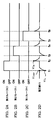
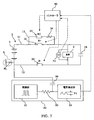
- FIG. 1 is a circuit diagram of a ground fault detector connection diagnosis apparatus according to a first embodiment of the present invention.
- FIGs. 2A-2D are timing charts showing changes in the detected voltage value when the relay according to the first embodiment is on and when it is off.
- FIG. 3 is a flowchart illustrating a connection diagnosis routine executed by the controller according to the first embodiment.
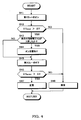
- FIG. 4 is a flowchart for explaining a third relay connection diagnosis subroutine executed by the controller.
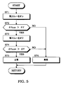
- FIG. FIG. 5 is a flowchart illustrating a second relay connection diagnosis subroutine executed by the controller.
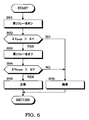
- FIG. 6 is a flowchart for explaining a first relay connection diagnosis subroutine executed by the controller.
- FIG. 7 is a circuit diagram of a ground fault detector connection diagnostic device according to a second embodiment of the present invention.
- FIG. FIG. 8 is a flowchart illustrating a connection diagnosis routine executed by the controller according to the second embodiment.
- FIG. 1-FIG. With reference to FIG. 6, a ground fault detector connection diagnosis apparatus for an electric vehicle according to a first embodiment of the present invention will be described.
- the electric vehicle includes a battery 1 that is a high-output DC power source and a load 2 such as a driving motor for traveling.
- the battery 1 and the load 2 are electrically connected by a high voltage circuit 3.
- the high-power circuit 3 includes three connection lines 11-13 and a large-capacity smoothing capacitor 14 installed in parallel with the load 2.
- the first connection line 11 connects the positive electrode of the battery 1 and the positive electrode terminal of the negative electrode 2.
- a first relay 21 is provided in the first connection line 11.
- the second connection line 12 connects the negative electrode of the battery 1 and the negative electrode terminal of the load 2.
- a second relay 22 is provided on the second connection line 12.
- the third connection line 13 is connected to the second connection line 12 so as to bypass the second relay 22.
- the third connection line 13 is provided with a third relay 23 and a resistor 24 in series.
- the resistance value of the resistor 24 is set based on the voltage of the battery 1 and the capacitance of the smoothing capacitor 14.
- a ground fault detector 30 for detecting a ground fault in the high power circuit 3 is installed.
- the ground fault detector 30 operates by supplying power from a small output power source different from the battery 1.
- the ground fault detector 30 includes an oscillation unit 31 that oscillates a rectangular pulse signal and a voltage detection unit 32.
- the oscillation unit 31 is connected to the second connection line 12 between the negative electrode of the battery 1 and the second relay 22 via the resistor 33 and the coupling capacitor 34.
- the voltage detector 32 detects the voltage between the resistor 33 and the coupling capacitor 34, thereby detecting the peak value of the rectangular pulse signal oscillated from the oscillator 31 as the voltage value V1.
- a ground fault resistance RA is formed as shown by a broken line area A. Due to the ground fault resistance RA , The voltage value V1 detected by the voltage detection unit 32 decreases.
- the ground fault detection by the ground fault detector 30 is performed while the vehicle is traveling.
- the ground fault is not limited to the position of the region A in the figure, and can occur at any position of the high-voltage circuit 3. Further, even when a ground fault occurs at any position in the high voltage circuit 3, the impedance of the high voltage circuit 3 changes.
- the ground fault detector 30 detects the change that the impedance change caused by the ground fault has on the voltage value V ⁇ b> 1 of the rectangular pulse signal of the oscillation unit 31.
- the ground fault detector 30 is connected to the second connection line 12 between the negative electrode of the battery 1 and the second relay 22, but the first connection line 11 between the positive electrode of the battery 1 and the first relay 21. You may connect to.
- the controller 40 includes a microcomputer having a central processing unit (CPU), a read only memory (ROM), a random access memory (RAM), and an input / output interface (I / O interface). It is also possible to configure the controller 40 with a plurality of microcomputers.
- the controller 40 receives signals from a voltage sensor 41 that detects the voltage across the load 2, the voltage detector 32 of the ground fault detector 30, and other sensors that detect the state of the vehicle.
- the controller 40 diagnoses the connection state of the ground fault detector 30 by switching the first to third relays 21-23 on or off.
- FIGs. The principle of the connection diagnosis of the ground fault detector 30 will be described with reference to 2A-2D.
- FIG. 2A when the third relay 23 is turned on at time t1 from the state where the first to third relays 21-23 are turned off, FIG. As shown in 2D, the voltage value V1 detected by the voltage detector 32 of the ground fault detector 30 temporarily decreases. Since the high-power circuit 3 has a parasitic capacitance, when the third relay 23 is turned on, the impedance in the high-power circuit 3 temporarily increases due to the parasitic capacitance.
- the voltage change amount ⁇ V RCON is obtained from the difference between the reference voltage value V1 DEF before the third relay 23 is turned on and the minimum voltage value V1 L when the third relay 23 is turned on, and the voltage change amount ⁇ V RCON is calculated .
- FIG. 2A when the third relay 23 is turned off at time t2, FIG. As shown in 2D, the voltage value V1 detected by the voltage detector 32 of the ground fault detector 30 temporarily increases.
- the impedance in the high voltage circuit 3 temporarily decreases due to the parasitic capacitance, so the ground fault detector 30 is normally connected to the high voltage circuit 3 via the third relay 23.
- the voltage value V1 detected by the voltage detector 32 increases. Therefore, the voltage change amount ⁇ V RCOFF is obtained from the difference between the reference voltage value V1 DEF and the maximum voltage value V1 H when the third relay 23 is turned off, and the voltage change amount ⁇ RCOFF is compared with the determination value ⁇ V. It is possible to determine whether or not the fault detector 30 is normally connected to the high voltage circuit 3 via the third relay 23.
- the ground fault detector 30 when the second relay 22 is turned on at time t3 and the second relay 22 is turned off at time t4, the ground fault detector 30 is normally connected to the high voltage circuit 3 via the second relay 22.
- the voltage variation [Delta] V R-ON reference voltage value V1 DEF calculated from the difference between the minimum voltage value V1 L when on the second relay 22, the voltage change amount [Delta] V R-OFF is a reference voltage value V1 DEF It is obtained from the difference from the maximum voltage value V1 H when the second relay 22 is off.
- FIG. 2C when the first relay 21 is turned on at time t5 and the first relay 21 is turned off at time t6, the ground fault detector 30 is normally connected to the high voltage circuit 3 via the first relay 21.
- the connection diagnosis routine is performed at the timing of at least one of when the main switch of the electric vehicle is turned on and off. Before the connection diagnosis control is performed, the first to third relays 21 to 23 are turned off.
- the controller 40 controls the oscillating unit 31 of the ground fault detector 30 so as to oscillate a rectangular pulse signal.
- the controller 40 stores the voltage value V1 detected by the voltage detector 32 of the ground fault detector 30 as the reference voltage value V1 DEF when the first to third relays 21-23 are turned off.
- the controller 40 determines whether or not the reference voltage value V1 DEF is greater than a predetermined ground fault determination voltage value V0.
- step S4 When the reference voltage value V1 DEF is larger than the ground fault determination voltage value V0, the controller 40 performs the process of step S4.
- the controller 40 determines that a ground fault has occurred in the battery 1 or the high-voltage circuit 3 near the battery 1. If a ground fault is detected in this way, the ground fault detector 30 is normally connected to the high voltage circuit 3, so the controller 40 does not perform a detailed connection diagnosis in step S ⁇ b> 11. Process.
- step S4 the controller 40 performs a third relay connection diagnosis. This diagnosis is shown in FIG. This is performed by the subroutine shown in FIG.
- step S5 the controller 40 determines whether or not the ground fault detector 30 is normally connected to the high voltage circuit 3 via the third relay 23 from the diagnosis result of step S4. If normal, the controller 40 performs the process of step S6. In the case of abnormality, the controller 40 performs the process of step S12.
- step S6 the controller 40 determines whether or not the first relay 21 is fixed on from the diagnosis result in step S4. If it is not on-fixed, the controller 40 performs step S7. If it is on-fixed, the controller 40 performs the process of step S12. In step S7, the controller 40 performs a second relay connection diagnosis. This diagnosis is shown in FIG. The subroutine shown in FIG.
- step S ⁇ b> 8 the controller 40 determines whether the ground fault detector 30 is normally connected to the high voltage circuit 3 via the second relay 22 from the diagnosis result of step S ⁇ b> 7. If it is normal, the controller 40 performs the process of step S9. In the case of abnormality, the controller 40 performs the process of step S12. In step S9, the controller 40 performs a first relay connection diagnosis. This diagnosis is shown in FIG. This is performed by the subroutine shown in FIG. In step S ⁇ b> 10, the controller 40 determines whether or not the ground fault detector 30 is normally connected to the high voltage circuit 3 via the first relay 21 from the diagnosis result of step S ⁇ b> 9. If normal, the controller 40 performs the process of step S11.
- step S12 the controller 40 diagnoses that the connection between the ground fault detector 30 and the high voltage circuit 3 is abnormal, notifies the driver of the connection abnormality, and ends the process.
- FIG. The third relay connection diagnosis subroutine will be described with reference to FIG.
- step S41 the controller 40 switches the third relay 23 from off to on.
- step S42 the controller 40 determines whether or not the voltage change amount ⁇ V RCON when the third relay 23 is on is larger than the determination value ⁇ V.
- the voltage change amount ⁇ V RCON is obtained by subtracting the minimum voltage value V1 L when the third relay 23 is on from the quasi-voltage value V1 DEF .
- the controller 40 executes the process of step S43.
- the controller 40 executes the process of step S48 and determines that the ground fault detector 30 is not normally connected via the third relay 23.
- step S43 the controller 40 determines whether or not the voltage V2 across the load 2 detected by the voltage sensor 41 has increased when the third relay 23 is turned on. The voltage V2 across the load 2 increases when the third relay 23 is turned on when the first relay 21 is stuck on.
- step S44 the controller 40 performs the process of step S44 and determines that the first relay 21 is fixed on.
- the controller 40 executes the process of step S45.
- step S45 the controller 40 switches the third relay 23 from on to off.
- step S46 the controller 40 determines whether or not the voltage change amount ⁇ V RCOFF when the third relay 23 is off is larger than the determination value ⁇ V.
- the voltage change amount ⁇ V RCOFF is obtained by subtracting the quasi-voltage value V1 DEF from the maximum voltage value V1 H when the third relay 23 is off.
- step S47 When the voltage change amount ⁇ V RCOFF is larger than the determination value ⁇ V, the controller 40 executes the process of step S47.
- step S48 When the voltage change amount ⁇ V RCOFF is smaller than the determination value ⁇ V, the controller 40 executes the process of step S48.
- step S ⁇ b> 47 the controller 40 determines that the ground fault detector 30 is normally connected via the third relay 23.
- step S ⁇ b> 48 the controller 40 determines that the ground fault detector 30 is not normally connected via the third relay 23.
- FIG. The second relay connection diagnosis subroutine will be described with reference to FIG.
- step S71 the controller 40 switches the second relay 22 from off to on.
- Step S72 the controller 40 determines whether or not the voltage change amount ⁇ VR -ON when the second relay 22 is on is larger than the determination value ⁇ V.
- the voltage change amount ⁇ V R-ON is obtained by subtracting the minimum voltage value V1 L when the second relay 22 is on from the quasi-voltage value V1 DEF .
- the controller 40 executes the process of step S73.
- the controller 40 executes the process of step S76, and the ground fault detector 30 is not normally connected via the second relay 22. judge.
- step S73 the controller 40 switches the second relay 22 from on to off.
- step S74 the controller 40 determines whether or not the voltage change amount ⁇ VR -OFF when the second relay 22 is OFF is larger than the determination value ⁇ V.
- the voltage change amount ⁇ VR -OFF is obtained by subtracting the quasi-voltage value V1 DEF from the maximum voltage value V1 H when the second relay 22 is off. If the voltage change amount ⁇ VR -OFF is larger than the determination value ⁇ V, the controller 40 executes the process of step S75. When the voltage change amount ⁇ VR -OFF is smaller than the determination value ⁇ V, the controller 40 executes the process of step S76. In step S ⁇ b> 75, the controller 40 determines that the ground fault detector 30 is normally connected via the second relay 22.
- step S76 the controller 40 determines that the ground fault detector 30 is not normally connected via the second relay 22.
- FIG. The first relay connection diagnosis subroutine will be described with reference to FIG.
- step S91 the controller 40 switches the first relay 21 from off to on.
- step S92 the controller 40 determines whether or not the voltage change amount ⁇ VR + ON when the first relay 21 is on is larger than the determination value ⁇ V.
- the voltage change amount ⁇ V R + ON is obtained by subtracting the minimum voltage value V1 L when the first relay 21 is on from the quasi-voltage value V1 DEF .
- the controller 40 executes the process of step S93.
- step S96 determines that the ground fault detector 30 is not normally connected via the first relay 21.
- step S93 the controller 40 switches the first relay 21 from on to off.
- step S94 the controller 40 determines whether or not the voltage change amount ⁇ VR + OFF when the first relay 21 is off is larger than the determination value ⁇ V.
- Voltage variation [Delta] V R + OFF is determined by subtracting the reference voltage value V1 DEF from the maximum voltage value V1 H when off the first relay 21. If the voltage change amount ⁇ VR + OFF is larger than the determination value ⁇ V, the controller 40 executes the process of step S95.
- step S ⁇ b> 95 the controller 40 determines that the ground fault detector 30 is normally connected via the first relay 21.
- step S ⁇ b> 96 the controller 40 determines that the ground fault detector 30 is not normally connected via the first relay 21.
- the connection diagnostic device for the ground fault detector 30 can obtain the following effects.
- connection diagnostic device Since the connection diagnostic device detects a change in the voltage value detected by the voltage detection unit 32 of the ground fault detector 30 when the first to third relays 21-23 are turned on and off, based on the amount of voltage change. It is possible to diagnose whether the ground fault detector 30 is normally connected to the high voltage circuit 3 via the first to third relays 21-23. Therefore, it is possible to diagnose the connection state between the high voltage circuit 3 and the ground fault detector 30 with a simpler configuration than the conventional method of providing a ground circuit that generates a pseudo ground fault. Since the connection diagnosis device performs the third relay connection diagnosis prior to the first relay connection diagnosis and the second relay connection diagnosis, even if the first relay 21 is fixed on, it is in series with the third relay 23.
- the resistor 24 By the action of the resistor 24 provided in the circuit, it is possible to avoid a large current from flowing through the high voltage circuit 3 during connection diagnosis.
- the third relay connection diagnosis it is determined whether the first relay 21 is on-fixed based on the voltage across the load 2, and only when the first relay 21 is not on-fixed, the second relay connection diagnosis is performed. 1 Carry out relay connection diagnosis. Since it is guaranteed that the first relay 21 is not on-fixed, even if the second relay 22 is turned on by the second relay connection diagnosis, a large current does not flow through the high-power circuit 3 during the connection diagnosis.
- FIG. 7 and FIG. 8 the connection diagnostic apparatus of the ground fault detector 30 for electric vehicles by 2nd Embodiment of this invention is demonstrated.
- FIG. 8 As shown in FIG.
- the third connection line 13 is connected to the first connection line 11 so as to bypass the first relay 21.
- the controller 40 is configured as FIG.
- the connection diagnosis routine shown in FIG. In this connection diagnosis routine, steps that perform the same processing as in the first embodiment are assigned the same step numbers as in the first embodiment.
- FIG. 8 the controller 40 performs the third relay connection diagnosis prior to the first relay connection diagnosis and the second relay connection diagnosis in step S4. At the time of the third relay connection diagnosis, the controller 40 diagnoses the on-fixation of the second relay 22 based on the voltage across the load 2 at the time of the third relay connection diagnosis.
- step S13 the controller 40 determines whether or not the second relay 22 is fixed on from the diagnosis result in step S4. Only when the second relay 22 is not on-fixed, the controller 40 performs the first relay connection diagnosis in step S9, and then executes the second relay connection diagnosis in step S7. In the connection diagnostic device for the ground fault detector 30 described above, the same effect as in the first embodiment can be obtained. At the time of the third relay connection diagnosis, it is determined whether the second relay 22 is on-fixed based on the voltage across the load 2, and only when the second relay 22 is not on-fixed, the first relay connection diagnosis is performed. 2. Conduct relay connection diagnosis.
- the third connection line 13 is not necessarily required, and the connection diagnosis by the first relay 21 for the first connection line 11 and the connection diagnosis by the second relay 22 for the second connection line 12. You may make it perform only.
- the connection diagnosis is performed using the voltage change amount both when the first to third relays 21-23 are turned on and off. However, the first to third relays are used.
- the connection diagnosis may be performed by using either one of the voltage change amounts at the time of turning on or off at 21-23.
- the connection diagnosis device for the ground fault detector 30 is applied to an electric vehicle, but may be applied to a hybrid vehicle or a fuel cell vehicle.
- the present invention provides a particularly favorable effect in application to a ground fault detector connected to an electric circuit via a relay.
- Exclusive properties or features encompassed by embodiments of the invention are claimed as follows.
Abstract
Description
したがって、本発明の目的は、簡素な構成で電気回路と地絡検出器との接続状態を診断することができる地絡検出器の接続診断装置を提供することを目的とする。
本発明は、電源の正極と負荷を接続する第1接続線と、電源の負極と負荷を接続する第2接続線とを有する電気回路に、カップリングコンデンサを介して接続されるとともにパルス信号を発振する発振部と、発振部とカップリングコンデンサの間におけるパルス信号の電圧値を検出する電圧検出部とを備える地絡検出器の接続診断装置である。接続診断装置は、第1接続線に設けられる第1リレーと、第2接続線に設けられる第2リレーと、プログラマブルコントローラと、を備える。プログラマブルコントローラは、第1リレーをオン又はオフにし、第1リレーのオン時又はオフ時に、電圧検出部によって検出される電圧値の変化量に基づいて、地絡検出器が第1リレーを介して電気回路と正常に接続しているか否かを判定し、第2リレーをオン又はオフにし、第2リレーのオン時又はオフ時に、電圧検出部によって検出される電圧値の変化量に基づいて、地絡検出器が第2リレーを介して電気回路と正常に接続しているか否かを判定する。
この発明の詳細は、他の特徴及び利点と同様に、明細書の以降の記載の中で説明されるとともに、添付された図面に示される。
FIGs.2A−2Dは、第1の実施形態によるリレーのオン時及びオフ時における検出電圧値の変化を示すタイミングチャートである。
FIG.3は、第1の実施形態によるコントローラが実行する接続診断ルーチンを説明するフローチャートである。
FIG.4は、コントローラが実行する第3リレー接続診断サブルーチンを説明するフローチャートである。
FIG.5は、コントローラが実行する第2リレー接続診断サブルーチンを説明するフローチャートである。
FIG.6は、コントローラが実行する第1リレー接続診断サブルーチンを説明するフローチャートである。
FIG.7は、この発明の第2の実施形態による地絡検出器の接続診断装置の回路図である。
FIG.8は、第2の実施形態によるコントローラが実行する接続診断ルーチンを説明するフローチャートである。
FIG.1に示すように、電気自動車は、大出力の直流電源であるバッテリ1と、走行用駆動モータ等の負荷2とを備える。バッテリ1と負荷2とは強電回路3によって電気的に接続される。
強電回路3は、3つの接続線11−13と、負荷2に対して並列に設置される大容量の平滑コンデンサ14と、を備える。
第1接続線11は、バッテリ1の正極と負極2の正極端子を接続する。第1接続線11には、第1リレー21が設けられる。
第2接続線12は、バッテリ1の負極と負荷2の負極端子を接続する。第2接続線12には、第2リレー22が設けられる。
第3接続線13は、第2リレー22をバイパスするように、第2接続線12と接続する。第3接続線13には、第3リレー23及び抵抗24が直列に設けられる。抵抗24の抵抗値は、バッテリ1の電圧と平滑コンデンサ14の静電容量に基づいて設定される。
上記した強電回路3には、強電回路3内における地絡を検出するための地絡検出器30が設置される。地絡検出器30は、バッテリ1とは異なる小出力電源からの電力供給により作動する。地絡検出器30は、矩形パルス信号を発振する発振部31と、電圧検出部32と、を備える。
発振部31は、抵抗33とカップリングコンデンサ34を介して、バッテリ1の負極と第2リレー22の間の第2接続線12に接続される。電圧検出部32は、抵抗33とカップリングコンデンサ34との間の電圧を検出ことで、発振部31から発振された矩形パルス信号の波高値を電圧値V1として検出する。
強電回路3の絶縁抵抗が低下して強電回路3と車体の間で地絡が発生すると、破線領域Aに示すように地絡抵抗RAが形成され、この地絡抵抗RAに起因して電圧検出部32で検出される電圧値V1が低下する。したがって、電圧検出部32によって検出される電圧値V1を監視し、電圧低下を検出することによって強電回路3での地絡を検出することが可能となる。地絡検出器30による地絡検出は車両走行中に実施される。
なお、地絡は、図の領域Aの位置に限らず、強電回路3のいかなる位置にも起こり得る。また、強電回路3のいかなる位置で地絡が生じた場合でも、強電回路3のインピーダンスが変化する。地絡検出器30は、地絡に起因するインピーダンス変化が発振部31の矩形パルス信号の電圧値V1に及ぼす変化を検出する。本実施形態では、地絡検出器30をバッテリ1の負極と第2リレー22の間の第2接続線12に接続したが、バッテリ1の正極と第1リレー21の間の第1接続線11に接続してもよい。
コントローラ40は、中央演算装置(CPU)、読み出し専用メモリ(ROM)、ランダムアクセスメモリ(RAM)及び入出力インタフェース(I/Oインタフェース)を備えたマイクロコンピュータで構成される。コントローラ40を複数のマイクロコンピュータで構成することも可能である。
コントローラ40には、負荷2の両端電圧を検出する電圧センサ41や、地絡検出器30の電圧検出部32、その他車両の状態を検出する各種センサからの信号が入力する。コントローラ40は、これら信号に基づき、第1−第3リレー21−23をオン又はオフに切り替えることで、地絡検出器30の接続状態を診断する。
FIGs.2A−2Dを参照して、地絡検出器30の接続診断の原理について説明する。
FIG.2Aに示すように第1−第3リレー21−23がオフにされている状態から時刻t1で第3リレー23をオンにすると、FIG.2Dに示すように地絡検出器30の電圧検出部32で検出される電圧値V1が一時的に低下する。強電回路3には寄生容量が存在するので、第3リレー23のオン時には、寄生容量に起因して強電回路3におけるインピーダンスが一時的に増大する。そのため、地絡検出器30が第3リレー23を介して強電回路3に正常に接続されている場合には、電圧検出部32で検出される電圧値V1が低下するのである。したがって、第3リレー23をオンにする前の基準電圧値V1DEFと、第3リレー23のオン時における最小電圧値V1Lとの差から電圧変化量ΔVRCONを求め、電圧変化量ΔVRCONを判定値ΔVと比較することによって、地絡検出器30が第3リレー23を介して強電回路3に正常に接続されているかどうかを判断することが可能となる。
FIG.2Aに示すように時刻t2で第3リレー23をオフにすると、FIG.2Dに示すように地絡検出器30の電圧検出部32で検出される電圧値V1は一時的に増加する。第3リレー23のオフ時には、寄生容量に起因して強電回路3におけるインピーダンスが一時的に低下するため、地絡検出器30が第3リレー23を介して強電回路3に正常に接続されている場合には、電圧検出部32で検出される電圧値V1が増加するのである。したがって、基準電圧値V1DEFと、第3リレー23のオフ時における最大電圧値V1Hとの差から電圧変化量ΔVRCOFFを求め、電圧変化量ΔRCOFFを判定値ΔVと比較することで、地絡検出器30が第3リレー23を介して強電回路3に正常に接続されているかどうかを判断することが可能となる。
FIG.2Bに示すように時刻t3で第2リレー22をオンにして時刻t4で第2リレー22をオフにすると、地絡検出器30が第2リレー22を介して強電回路3に正常に接続されている場合には、FIG.2Dに示すように、第2リレー22のオン時に電圧値V1が一時的に低下し、第2リレー22のオフ時に電圧値V1が一時的に増加する。したがって、第2リレー22のオン時又はオフ時における電圧変化量ΔVR−ON、ΔVR−OFFを検出することで、地絡検出器30が第2リレー22を介して強電回路3に正常に接続されているかどうかを判断できる。
なお、電圧変化量ΔVR−ONは基準電圧値V1DEFを、第2リレー22のオン時における最小電圧値V1Lの差から求められ、電圧変化量ΔVR−OFFは基準電圧値V1DEFと、第2リレー22のオフ時における最大電圧値V1Hとの差から求められる。
FIG.2Cに示すように時刻t5で第1リレー21をオンにして時刻t6で第1リレー21をオフにすると、地絡検出器30が第1リレー21を介して強電回路3に正常に接続されている場合には、FIG.2Dに示すように、第1リレー21のオン時に電圧値V1が一時的に低下し、第1リレー21のオフ時に電圧値V1が一時的に増加する。したがって、第1リレー21のオン時又はオフ時における電圧変化量ΔVR+ON、ΔVR+OFFを検出することで、地絡検出器30が第1リレー21を介して強電回路3に正常に接続されているかどうかを判断できる。
なお、電圧変化量ΔVR+ONは基準電圧値V1DEFと、第1リレー21のオン時における最小電圧値V1Lとの差から求められ、電圧変化量ΔVR+OFFは基準電圧値V1DEFと、第1リレー21のオフ時における最大電圧値V1Hとの差から求められる。
次に、FIG.3を参照して、コントローラ40が実行する地絡検出器30の接続診断ルーチンについて説明する。
接続診断ルーチンは、電気自動車のメインスイッチのオン時及びオフ時の少なくともいずれか一方のタイミングで実施される。接続診断制御の実施前には、第1−第3リレー21−23はオフにされている。
ステップS1では、コントローラ40は、矩形パルス信号を発振するように地絡検出器30の発振部31を制御する。
ステップS2では、コントローラ40は、第1−第3リレー21−23のオフ時に、地絡検出器30の電圧検出部32によって検出された電圧値V1を基準電圧値V1DEFとして記憶する。
ステップS3では、コントローラ40は、基準電圧値V1DEFが予め定めた地絡判定電圧値V0よりも大きいか否かを判定する。基準電圧値V1DEFが地絡判定電圧値V0よりも大きい場合には、コントローラ40はステップS4の処理を行う。
基準電圧値V1DEFが地絡判定電圧値V0よりも小さい場合には、コントローラ40は、バッテリ1やバッテリ1近傍の強電回路3に地絡が発生していると判定する。このように地絡が検出された場合には、地絡検出器30が正常に強電回路3に接続されていることにほかならないから、コントローラ40は詳細な接続診断を実施することなくステップS11の処理を行う。
ステップS4では、コントローラ40は第3リレー接続診断を実施する。この診断は、FIG.4に示すサブルーチンにより行われる。
ステップS5では、コントローラ40は、ステップS4の診断結果から、地絡検出器30が第3リレー23を介して強電回路3と正常に接続しているか否かを判定する。正常の場合には、コントローラ40はステップS6の処理を行う。異常の場合には、コントローラ40はステップS12の処理を行う。
ステップS6では、コントローラ40は、ステップS4の診断結果から、第1リレー21がオン固着していないかを判定する。オン固着していない場合には、コントローラ40はステップS7の処理を行う。オン固着している場合には、コントローラ40がステップS12の処理を行う。
ステップS7では、コントローラ40は第2リレー接続診断を実施する。この診断は、FIG.5に示すサブルーチンにより行われる。
ステップS8では、コントローラ40は、ステップS7の診断結果から、地絡検出器30が第2リレー22を介して強電回路3と正常に接続しているか否かを判定する。正常の場合には、コントローラ40はステップS9の処理を行う。異常の場合には、コントローラ40はステップS12の処理を行う。
ステップS9では、コントローラ40は第1リレー接続診断を実施する。この診断は、FIG.6に示すサブルーチンにより行われる。
ステップS10では、コントローラ40は、ステップS9の診断結果から、地絡検出器30が第1リレー21を介して強電回路3と正常に接続しているか否かを判定する。正常の場合には、コントローラ40はステップS11の処理を行う。異常の場合には、コントローラ40はステップS12の処理を行う。
ステップS11では、コントローラ40は、地絡検出器30と強電回路3との接続が正常であると診断して、処理を終了する。
ステップS12では、コントローラ40は、地絡検出器30と強電回路3との接続が異常であると診断し、接続異常を運転者に報知して、処理を終了する。
FIG.4を参照して、第3リレー接続診断サブルーチンについて説明する。
ステップS41では、コントローラ40は第3リレー23をオフからオンに切り替える。
ステップS42では、コントローラ40は、第3リレー23のオン時における電圧変化量ΔVRCONが判定値ΔVよりも大きいか否かを判定する。電圧変化量ΔVRCONは、準電圧値V1DEFから、第3リレー23のオン時における最小電圧値V1Lを減算して求められる。
電圧変化量ΔVRCONが判定値ΔVよりも大きい場合には、コントローラ40はステップS43の処理を実行する。電圧変化量ΔVRCONが判定値ΔVよりも小さい場合には、コントローラ40は、ステップS48の処理を実行し、地絡検出器30が第3リレー23を介して正常に接続されていないと判定する。
ステップS43では、コントローラ40は、第3リレー23のオン時に、電圧センサ41によって検出される負荷2の両端電圧V2が上昇したか否かを判定する。
第3リレー23のオン時に負荷2の両端電圧V2が上昇するのは、第1リレー21がオン固着している場合である。したがって、両端電圧V2が上昇した場合には、コントローラ40は、ステップS44の処理を実行し、第1リレー21がオン固着していると判定する。
これに対して、両端電圧V2が上昇しない場合には、コントローラ40はステップS45の処理を実行する。
ステップS45では、コントローラ40は第3リレー23をオンからオフに切り替える。
ステップS46では、コントローラ40は、第3リレー23のオフ時における電圧変化量ΔVRCOFFが判定値ΔVよりも大きいか否かを判定する。電圧変化量ΔVRCOFFは、第3リレー23のオフ時における最大電圧値V1Hから準電圧値V1DEFを減算して求められる。
電圧変化量ΔVRCOFFが判定値ΔVよりも大きい場合には、コントローラ40はステップS47の処理を実行する。電圧変化量ΔVRCOFFが判定値ΔVよりも小さい場合には、コントローラ40は、ステップS48の処理を実行する。
ステップS47では、コントローラ40は、地絡検出器30が第3リレー23を介して正常に接続されている判定する。
ステップS48では、コントローラ40は、地絡検出器30が第3リレー23を介して正常に接続されていないと判定する。
FIG.5を参照して、第2リレー接続診断サブルーチンについて説明する。
ステップS71では、コントローラ40は第2リレー22をオフからオンに切り替える。
ステップS72では、コントローラ40は、第2リレー22のオン時における電圧変化量ΔVR−ONが判定値ΔVよりも大きいか否かを判定する。電圧変化量ΔVR−ONは、準電圧値V1DEFから、第2リレー22のオン時における最小電圧値V1Lを減算して求められる。
電圧変化量ΔVR−ONが判定値ΔVよりも大きい場合には、コントローラ40はステップS73の処理を実行する。電王変化量ΔVR−ONが判定値ΔVよりも小さい場合には、コントローラ40は、ステップS76の処理を実行し、地絡検出器30が第2リレー22を介して正常に接続されていないと判定する。
ステップS73では、コントローラ40は第2リレー22をオンからオフに切り替える。
ステップS74では、コントローラ40は、第2リレー22のオフ時における電圧変化量ΔVR−OFFが判定値ΔVよりも大きいか否かを判定する。電圧変化量ΔVR−OFFは、第2リレー22のオフ時における最大電圧値V1Hから準電圧値V1DEFを減算して求められる。
電圧変化量ΔVR−OFFが判定値ΔVよりも大きい場合には、コントローラ40はステップS75の処理を実行する。電圧変化量ΔVR−OFFが判定値ΔVよりも小さい場合には、コントローラ40は、ステップS76の処理を実行する。
ステップS75では、コントローラ40は、地絡検出器30が第2リレー22を介して正常に接続されている判定する。
ステップS76では、コントローラ40は、地絡検出器30が第2リレー22を介して正常に接続されていないと判定する。
FIG.6を参照して、第1リレー接続診断サブルーチンについて説明する。
ステップS91では、コントローラ40は第1リレー21をオフからオンに切り替える。
ステップS92では、コントローラ40は、第1リレー21のオン時における電圧変化量ΔVR+ONが判定値ΔVよりも大きいか否かを判定する。電圧変化量ΔVR+ONは、準電圧値V1DEFから、第1リレー21のオン時における最小電圧値V1Lを減算して求められる。
電圧変化量ΔVR+ONが判定値ΔVよりも大きい場合には、コントローラ40はステップS93の処理を実行する。電圧変化量ΔVR+ONが判定値ΔVよりも小さい場合には、コントローラ40は、ステップS96の処理を実行し、地絡検出器30が第1リレー21を介して正常に接続されていないと判定する。
ステップS93では、コントローラ40は第1リレー21をオンからオフに切り替える。
ステップS94では、コントローラ40は、第1リレー21のオフ時における電圧変化量ΔVR+OFFが判定値ΔVよりも大きいか否かを判定する。電圧変化量ΔVR+OFFは、第1リレー21のオフ時における最大電圧値V1Hから基準電圧値V1DEFを減算して求められる。
電圧変化量ΔVR+OFFが判定値ΔVよりも大きい場合には、コントローラ40はステップS95の処理を実行する。電圧変化量ΔVR+OFFが判定値ΔVよりも小さい場合には、コントローラ40は、ステップS96の処理を実行する。
ステップS95では、コントローラ40は、地絡検出器30が第1リレー21を介して正常に接続されている判定する。
ステップS96では、コントローラ40は、地絡検出器30が第1リレー21を介して正常に接続されていないと判定する。
以上により、地絡検出器30の接続診断装置では、下記の効果を得ることができる。
地絡検出器30が第1−第3リレー21−23を介して強電回路3に正常に接続されている場合には、第1−第3リレー21−23のオン時及びオフ時に、強電回路3の寄生容量に起因して地絡検出器30の電圧検出部32で検知される電圧値が変化する。接続診断装置は、第1−第3リレー21−23のオン時及びオフ時に、地絡検出器30の電圧検出部32で検知される電圧値の変化を検出するので、電圧変化量に基づいて地絡検出器30が第1−第3リレー21−23を介して強電回路3と正常に接続されているどうかを診断することができる。したがって、擬似的な地絡を発生させる接地回路を設ける従来手法よりも簡素な構成で、強電回路3と地絡検出器30との接続状態を診断することが可能となる。
接続診断装置は第3リレー接続診断を第1リレー接続診断及び第2リレー接続診断に先駆けて行うので、仮に第1リレー21がオン固着している場合であっても、第3リレー23と直列に設けられる抵抗24の作用によって、接続診断時に強電回路3に大電流が流れることを回避できる。
第3リレー接続診断時に負荷2の両端電圧に基づいて第1リレー21のオン固着を判定し、第1リレー21がオン固着していない場合にのみ、第2リレー接続診断をし、その後に第1リレー接続診断を実施する。第1リレー21がオン固着していないことは保証されているので、第2リレー接続診断によって第2リレー22をオンにしても、接続診断時に強電回路3に大電流が流れることがない。また、第1リレー接続診断は、第2リレー接続診断後に実施されるので、第1リレー接続診断によって第1リレー21をオンにしても、接続診断時に強電回路3に大電流が流れることがない。
接続診断装置は、強電回路3の寄生容量に起因して第1−第3リレー21−23のオン時又はオフ時に生じる一時的な電圧値変化の最大変化量を用いて接続診断を行うので、診断時間を短期化できる。
次に、FIG.7及びFIG.8を参照して、この発明の第2の実施形態による電気自動車用の地絡検出器30の接続診断装置について説明する。
FIG.7に示すように、第2の実施形態による地絡検出器30の接続診断装置では、第3接続線13は、第1リレー21をバイパスするように第1接続線11に接続する。
このように構成される接続診断装置では、コントローラ40は、FIG.8に示す接続診断ルーチンを実施する。この接続診断ルーチンでは、第1の実施形態と同じ処理を行うステップについては、第1の実施形態と同じステップ番号を付した。
FIG.8に示すように、コントローラ40は、ステップS4で第3リレー接続診断を第1リレー接続診断及び第2リレー接続診断に先駆けて実施する。第3リレー接続診断時には、コントローラ40は、第3リレー接続診断時に負荷2の両端電圧に基づいて第2リレー22のオン固着を診断する。そして、ステップS13では、コントローラ40は、ステップS4の診断結果から、第2リレー22がオン固着していないかを判定する。第2リレー22がオン固着していない場合にのみ、コントローラ40はステップS9で第1リレー接続診断をし、その後のステップS7で第2リレー接続診断を実施する。
上記した地絡検出器30の接続診断装置では、第1の実施形態と同様の効果を得ることができる。
第3リレー接続診断時に負荷2の両端電圧に基づいて第2リレー22のオン固着を判定し、第2リレー22がオン固着していない場合にのみ、第1リレー接続診断をし、その後に第2リレー接続診断を実施する。第2リレー22がオン固着していないことは保証されているので、第1リレー接続診断によって第1リレー21をオンにしても、接続診断時に強電回路3に大電流が流れることがない。また、第2リレー接続診断は、第1リレー接続診断後に実施されるので、第2リレー接続診断によって第2リレー22をオンにしても、接続診断時に強電回路3に大電流が流れることがない。
以上の説明に関して、2009年6月12日を出願日とする日本国における特願2009−140927号の内容をここに引用により組み込む。
以上、この発明をいくつかの特定の実施形態を通じて説明してきたが、この発明は上記の各実施形態に限定されるものではない。当業者にとっては、クレームの技術範囲でこれらの実施形態に様々な修正あるいは変更を加えることが可能である。
例えば、第1及び第2の実施形態では、第3接続線13は必ずしも必要ではなく、第1接続線11の第1リレー21による接続診断及び第2接続線12の第2リレー22による接続診断のみを行うようにしてもよい。
また、第1及び第2の実施形態では、第1−第3リレー21−23のオン時及びオフ時両方の電圧変化量を用いて接続診断を実施しているが、第1−第3リレー21−23のオン時又はオフ時のいずれか一方の電圧変化量を用いて接続診断を実施してもよい。
さらに、第1及び第2の実施形態では、地絡検出器30の接続診断装置を電気自動車に適用したが、ハイブリット車や燃料電池車に適用してもよい。
この発明の実施形態が包含する排他的性質あるいは特長は、以下のようにクレームされる。
Claims (6)
- 電源(1)の正極と負荷(2)を接続する第1接続線(11)と、電源(1)の負極と負荷(2)を接続する第2接続線(12)とを有する電気回路(3)に、カップリングコンデンサ(34)を介して接続されるとともにパルス信号を発振する発振部(31)と、前記発振部(31)と前記カップリングコンデンサ(34)の間におけるパルス信号の電圧値を検出する電圧検出部(32)とを備える地絡検出器(30)の接続診断装置において、
前記第1接続線(11)に設けられる第1リレー(21)と、
前記第2接続線(12)に設けられる第2リレー(22)と、
次のようにプログラムされたプログラマブルコントローラ(40)と、
前記第1リレー(21)をオン又はオフにし、
前記第1リレー(21)のオン時又はオフ時に、前記電圧検出部(32)によって検出される電圧値の変化量に基づいて、前記地絡検出器(30)が第1リレー(21)を介して前記電気回路(3)と正常に接続しているか否かを判定し、
前記第2リレー(22)をオン又はオフにし、
前記第2リレー(22)のオン時又はオフ時に、前記電圧検出部(32)によって検出される電圧値の変化量に基づいて、前記地絡検出器(30)が第2リレー(22)を介して前記電気回路(3)と正常に接続しているか否かを判定する、
を備える接続診断装置。 - 請求項1の接続診断装置において、
前記第1リレー(21)又は前記第2リレー(22)をバイパスするように前記第1接続線(11)又は前記第2接続線(12)に接続される第3接続線(13)と、
前記第3接続線(13)に設けられる第3リレー(23)と、
前記第3接続線(13)に設けられ、前記第3リレー(23)と直列に配置される抵抗(24)と、をさらに備え、
前記プログラマブルコントローラ(40)は、前記第3リレー(23)をオン又はオフにし、前記第3リレー(23)のオン時又はオフ時に、前記電圧検出部(32)によって検出される電圧値の変化量に基づいて、前記地絡検出器(30)が第3リレー(23)を介して前記電気回路(3)と正常に接続しているか否かを判定する。 - 請求項2の接続診断装置において、
前記電圧検出部(32)によって検出される電圧値の変化量は、前記電気回路(3)の寄生容量に起因してリレー(21−23)のオン時又はオフ時に生じる一時的な電圧値変化の最大変化量である。 - 請求項2又は請求項3の接続診断装置において、
前記プログラマブルコントローラ(40)は、第3リレー(23)による接続診断を、第1リレー(21)による接続診断及び第2リレー(22)による接続診断に先駆けて実施する。 - 請求項4の接続診断装置において、
前記負荷(2)の両端電圧を検出する負荷電圧検出部(41)をさらに備え、
前記第3接続線(13)は、前記第2接続線(12)に接続され、
前記プログラマブルコントローラ(40)は、前記第3リレー(23)による接続診断での前記第3リレー(23)のオン時に前記負荷(2)の両端電圧に基づいて前記第1リレー(21)のオン固着判定を行い、
前記第1リレー(21)がオン固着していない場合にのみ、前記第2リレー(22)による接続診断を行い、その後に前記第1リレー(21)による接続診断を行う。 - 請求項4の接続診断装置において、
前記負荷(2)の両端電圧を検出する負荷電圧検出部(41)をさらに備え、
前記第3接続線(13)は前記第1接続線(11)に接続され、
前記プログラマブルコントローラ(40)は、前記第3リレー(23)による接続診断での前記第3リレー(23)のオン時に前記負荷(2)の両端電圧に基づいて前記第2リレー(22)のオン固着判定を行い、
前記第2リレー(22)がオン固着していない場合にのみ、前記第1リレー(21)による接続診断を行い、その後に前記第2リレー(22)による接続診断を行う。
Priority Applications (4)
| Application Number | Priority Date | Filing Date | Title |
|---|---|---|---|
| US13/263,251 US8847605B2 (en) | 2009-06-12 | 2010-05-19 | Connection diagnostic apparatus for ground fault detector |
| CN201080026143.XA CN102460193B (zh) | 2009-06-12 | 2010-05-19 | 接地检测器的连接诊断装置 |
| EP10786065.2A EP2442120B1 (en) | 2009-06-12 | 2010-05-19 | Connection diagnostic device for ground fault detector |
| JP2011518406A JP5533864B2 (ja) | 2009-06-12 | 2010-05-19 | 地絡検出器の接続診断装置 |
Applications Claiming Priority (2)
| Application Number | Priority Date | Filing Date | Title |
|---|---|---|---|
| JP2009140927 | 2009-06-12 | ||
| JP2009-140927 | 2009-06-12 |
Publications (1)
| Publication Number | Publication Date |
|---|---|
| WO2010143534A1 true WO2010143534A1 (ja) | 2010-12-16 |
Family
ID=43308789
Family Applications (1)
| Application Number | Title | Priority Date | Filing Date |
|---|---|---|---|
| PCT/JP2010/058855 WO2010143534A1 (ja) | 2009-06-12 | 2010-05-19 | 地絡検出器の接続診断装置 |
Country Status (5)
| Country | Link |
|---|---|
| US (1) | US8847605B2 (ja) |
| EP (1) | EP2442120B1 (ja) |
| JP (1) | JP5533864B2 (ja) |
| CN (1) | CN102460193B (ja) |
| WO (1) | WO2010143534A1 (ja) |
Cited By (9)
| Publication number | Priority date | Publication date | Assignee | Title |
|---|---|---|---|---|
| JP2013079903A (ja) * | 2011-10-05 | 2013-05-02 | Denso Corp | 車両の漏電検出装置 |
| JP2014234061A (ja) * | 2013-05-31 | 2014-12-15 | 日本電産エレシス株式会社 | 電子制御装置 |
| JP2015214264A (ja) * | 2014-05-12 | 2015-12-03 | トヨタ自動車株式会社 | 蓄電システム |
| JPWO2013190733A1 (ja) * | 2012-06-18 | 2016-02-08 | 日立オートモティブシステムズ株式会社 | リーク検出装置 |
| CN105946584A (zh) * | 2016-05-17 | 2016-09-21 | 福建万众百源实业有限公司 | 一种汽车电池继电器粘连检测保护电路 |
| JP2018026889A (ja) * | 2016-08-08 | 2018-02-15 | 株式会社デンソーテン | 固着検出装置および電池システム |
| WO2020170557A1 (ja) | 2019-02-19 | 2020-08-27 | 三洋電機株式会社 | 漏電検出装置、車両用電源システム |
| JP2020159922A (ja) * | 2019-03-27 | 2020-10-01 | 株式会社豊田自動織機 | 漏電検知回路 |
| US11971458B2 (en) | 2019-02-19 | 2024-04-30 | Sanyo Electric Co., Ltd. | Electrical fault detection device and vehicle power supply system |
Families Citing this family (21)
| Publication number | Priority date | Publication date | Assignee | Title |
|---|---|---|---|---|
| GB201120036D0 (en) * | 2011-11-21 | 2012-01-04 | The Technology Partnership Plc | Method of providing power and data |
| DE102011089145A1 (de) * | 2011-12-20 | 2013-06-20 | Robert Bosch Gmbh | Schutzvorrichtung, Verfahren und Energieversorgungssystem |
| JP6011455B2 (ja) * | 2012-05-17 | 2016-10-19 | 株式会社豊田自動織機 | 負荷駆動装置 |
| FR2992429B1 (fr) * | 2012-06-20 | 2014-07-18 | Renault Sa | Dispositif de mesure de resistance de prise de terre et chargeur pour vehicule embarque muni d'un tel dispositif |
| US9911249B2 (en) * | 2012-09-20 | 2018-03-06 | GM Global Technology Operations LLC | Fail operational power system diagnostics |
| CN102902264B (zh) * | 2012-10-09 | 2015-01-14 | 埃泰克汽车电子(芜湖)有限公司 | 一种电动车窗控制器的测试方法 |
| JP5713030B2 (ja) * | 2013-01-15 | 2015-05-07 | トヨタ自動車株式会社 | 電動車両および電動車両の絶縁状態判定方法 |
| US9075098B2 (en) | 2013-01-16 | 2015-07-07 | Thomas Michael Schurman | Plug-in electric vehicle charger validation and test device |
| CN103983882B (zh) * | 2013-02-08 | 2016-12-28 | 施耐德电器工业公司 | 检测数字输入信号线连通性的装置及方法 |
| US10279218B2 (en) | 2013-09-03 | 2019-05-07 | Bridgestone Sports Co., Ltd. | Golf ball |
| JP6146332B2 (ja) * | 2013-09-11 | 2017-06-14 | トヨタ自動車株式会社 | リレーの固着判別システム |
| JP6252106B2 (ja) * | 2013-10-31 | 2017-12-27 | 日本電産リード株式会社 | 接触子のメンテナンス方法及び検査装置 |
| FR3028049B1 (fr) * | 2014-11-04 | 2016-12-09 | Continental Automotive France | Procede de diagnostic d'un defaut a la masse d'un organe de demarrage / arret d'un vehicule automobile |
| JP6476972B2 (ja) * | 2015-02-17 | 2019-03-06 | 株式会社デンソー | 漏電判定装置 |
| US10001519B2 (en) * | 2015-06-12 | 2018-06-19 | Allegro Microsystems, Llc | Ground reference fault detection in circuits with multiple ground references |
| CN104986049B (zh) * | 2015-06-19 | 2017-11-03 | 安徽江淮汽车集团股份有限公司 | 一种接触器控制方法 |
| US9510289B1 (en) * | 2015-11-05 | 2016-11-29 | Silicon Laboratories, Inc. | In system calibration of wake up timer |
| CN108051696A (zh) * | 2017-12-11 | 2018-05-18 | 李玉诚 | 一种用于检测装置连接状态的检测方法 |
| US11092654B2 (en) * | 2019-06-28 | 2021-08-17 | Teradyne, Inc. | Measuring a leakage characteristic of a signal path |
| JPWO2021106284A1 (ja) * | 2019-11-26 | 2021-06-03 | ||
| JP7095016B2 (ja) * | 2020-04-17 | 2022-07-04 | 富士電機株式会社 | 電力変換装置 |
Citations (6)
| Publication number | Priority date | Publication date | Assignee | Title |
|---|---|---|---|---|
| JPH10144194A (ja) * | 1996-11-07 | 1998-05-29 | Nissan Motor Co Ltd | 電気自動車の強電リレー診断装置 |
| JPH10221395A (ja) | 1997-02-07 | 1998-08-21 | Denso Corp | 電気自動車の地絡検知システム |
| JP2005149843A (ja) * | 2003-11-13 | 2005-06-09 | Nissan Motor Co Ltd | リレーの故障判定装置およびリレーの故障判定方法 |
| JP2005192324A (ja) * | 2003-12-25 | 2005-07-14 | Toyota Motor Corp | 電源系統の異常検知装置 |
| JP2007329045A (ja) * | 2006-06-08 | 2007-12-20 | Nissan Motor Co Ltd | リレー故障診断装置 |
| JP2009140927A (ja) | 2007-12-04 | 2009-06-25 | Hanwha Chem Corp | 燃料電池用独立電極触媒層及びこれを用いた膜−電極接合体の製造方法 |
Family Cites Families (9)
| Publication number | Priority date | Publication date | Assignee | Title |
|---|---|---|---|---|
| US5065104A (en) * | 1987-02-17 | 1991-11-12 | Alexander Kusko | Fault sensing with an artificial reference potential provided by an isolated capacitance effect |
| JP4133601B2 (ja) | 2003-06-06 | 2008-08-13 | 株式会社日本自動車部品総合研究所 | モータ駆動装置 |
| JP4003137B2 (ja) * | 2004-02-20 | 2007-11-07 | 株式会社デンソー | 地絡検出装置 |
| JP2006177840A (ja) | 2004-12-24 | 2006-07-06 | Nissan Motor Co Ltd | 地絡検出装置、地絡検出装置の診断方法 |
| JP4830376B2 (ja) * | 2005-07-11 | 2011-12-07 | 日産自動車株式会社 | 車両用地絡検出装置 |
| JP4826264B2 (ja) * | 2006-01-19 | 2011-11-30 | 日産自動車株式会社 | 地絡検出装置 |
| WO2008016179A1 (fr) * | 2006-08-04 | 2008-02-07 | Toyota Jidosha Kabushiki Kaisha | Système de détermination de résistance d'isolement, appareil de détermination de résistance d'isolement et procédé de détermination de résistance d'isolement |
| JP4422164B2 (ja) | 2007-03-28 | 2010-02-24 | 株式会社日立製作所 | 電力変換装置及び電力変換方法 |
| US7978446B2 (en) * | 2008-02-29 | 2011-07-12 | Caterpillar Inc. | High voltage ground fault detection system |
-
2010
- 2010-05-19 EP EP10786065.2A patent/EP2442120B1/en active Active
- 2010-05-19 CN CN201080026143.XA patent/CN102460193B/zh active Active
- 2010-05-19 JP JP2011518406A patent/JP5533864B2/ja not_active Expired - Fee Related
- 2010-05-19 WO PCT/JP2010/058855 patent/WO2010143534A1/ja active Application Filing
- 2010-05-19 US US13/263,251 patent/US8847605B2/en active Active
Patent Citations (6)
| Publication number | Priority date | Publication date | Assignee | Title |
|---|---|---|---|---|
| JPH10144194A (ja) * | 1996-11-07 | 1998-05-29 | Nissan Motor Co Ltd | 電気自動車の強電リレー診断装置 |
| JPH10221395A (ja) | 1997-02-07 | 1998-08-21 | Denso Corp | 電気自動車の地絡検知システム |
| JP2005149843A (ja) * | 2003-11-13 | 2005-06-09 | Nissan Motor Co Ltd | リレーの故障判定装置およびリレーの故障判定方法 |
| JP2005192324A (ja) * | 2003-12-25 | 2005-07-14 | Toyota Motor Corp | 電源系統の異常検知装置 |
| JP2007329045A (ja) * | 2006-06-08 | 2007-12-20 | Nissan Motor Co Ltd | リレー故障診断装置 |
| JP2009140927A (ja) | 2007-12-04 | 2009-06-25 | Hanwha Chem Corp | 燃料電池用独立電極触媒層及びこれを用いた膜−電極接合体の製造方法 |
Non-Patent Citations (1)
| Title |
|---|
| See also references of EP2442120A4 |
Cited By (10)
| Publication number | Priority date | Publication date | Assignee | Title |
|---|---|---|---|---|
| JP2013079903A (ja) * | 2011-10-05 | 2013-05-02 | Denso Corp | 車両の漏電検出装置 |
| JPWO2013190733A1 (ja) * | 2012-06-18 | 2016-02-08 | 日立オートモティブシステムズ株式会社 | リーク検出装置 |
| JP2014234061A (ja) * | 2013-05-31 | 2014-12-15 | 日本電産エレシス株式会社 | 電子制御装置 |
| JP2015214264A (ja) * | 2014-05-12 | 2015-12-03 | トヨタ自動車株式会社 | 蓄電システム |
| CN105946584A (zh) * | 2016-05-17 | 2016-09-21 | 福建万众百源实业有限公司 | 一种汽车电池继电器粘连检测保护电路 |
| JP2018026889A (ja) * | 2016-08-08 | 2018-02-15 | 株式会社デンソーテン | 固着検出装置および電池システム |
| WO2020170557A1 (ja) | 2019-02-19 | 2020-08-27 | 三洋電機株式会社 | 漏電検出装置、車両用電源システム |
| US11971458B2 (en) | 2019-02-19 | 2024-04-30 | Sanyo Electric Co., Ltd. | Electrical fault detection device and vehicle power supply system |
| JP2020159922A (ja) * | 2019-03-27 | 2020-10-01 | 株式会社豊田自動織機 | 漏電検知回路 |
| JP7135966B2 (ja) | 2019-03-27 | 2022-09-13 | 株式会社豊田自動織機 | 漏電検知回路 |
Also Published As
| Publication number | Publication date |
|---|---|
| EP2442120A1 (en) | 2012-04-18 |
| US20120025844A1 (en) | 2012-02-02 |
| JP5533864B2 (ja) | 2014-06-25 |
| CN102460193B (zh) | 2015-01-14 |
| JPWO2010143534A1 (ja) | 2012-11-22 |
| US8847605B2 (en) | 2014-09-30 |
| EP2442120B1 (en) | 2018-08-08 |
| CN102460193A (zh) | 2012-05-16 |
| EP2442120A4 (en) | 2013-05-01 |
Similar Documents
| Publication | Publication Date | Title |
|---|---|---|
| JP5533864B2 (ja) | 地絡検出器の接続診断装置 | |
| KR101291895B1 (ko) | 누전 검지 장치 | |
| JP5541743B2 (ja) | コンタクタの溶着検出装置 | |
| US7292042B2 (en) | Ground fault detector for vehicle | |
| US7557583B2 (en) | System and method for monitoring an electrical power relay in a hybrid electric vehicle | |
| CN106353692B (zh) | 用于在电气系统中检测存在漏电和/或继电器短路情况的监视系统 | |
| WO2007097190A1 (ja) | 電源装置の異常判定装置及び異常判定方法 | |
| JP5448545B2 (ja) | 車両用漏電検出装置 | |
| JP6518430B2 (ja) | 絶縁状態検出装置 | |
| JP2009290978A (ja) | 車両用電源回路の故障検出方法及びその装置 | |
| JP2007068249A (ja) | 電気自動車用リーク検出装置 | |
| JP6369407B2 (ja) | 故障検知システム | |
| JP2016161478A (ja) | コンタクタの故障判定装置 | |
| KR20090012456A (ko) | 고전압 사용 차량의 절연내력 측정 시스템 및 방법 | |
| JP6804320B2 (ja) | 地絡検出装置、電源システム | |
| WO2021106284A1 (ja) | 漏電検出装置、車両用電源システム | |
| JP2016130706A (ja) | 非接地電源の絶縁検出装置 | |
| JP2006177840A (ja) | 地絡検出装置、地絡検出装置の診断方法 | |
| JP2010188851A (ja) | 車両用電源装置 | |
| JP6742471B2 (ja) | 電池システム監視装置 | |
| JP2013213750A (ja) | 漏電検出装置 | |
| CN113858953A (zh) | 用于检测快速充电继电器的故障的系统及方法 | |
| JP3700514B2 (ja) | 駆動回路の故障検出装置 | |
| JP5615335B2 (ja) | 漏電検知装置 | |
| JP2023550781A (ja) | 高電圧車載電気システムのy静電容量の少なくとも1つの現在の静電容量値を決定する方法、及び電子計算装置 |
Legal Events
| Date | Code | Title | Description |
|---|---|---|---|
| WWE | Wipo information: entry into national phase |
Ref document number: 201080026143.X Country of ref document: CN |
|
| 121 | Ep: the epo has been informed by wipo that ep was designated in this application |
Ref document number: 10786065 Country of ref document: EP Kind code of ref document: A1 |
|
| WWE | Wipo information: entry into national phase |
Ref document number: 13263251 Country of ref document: US |
|
| ENP | Entry into the national phase |
Ref document number: 2011518406 Country of ref document: JP Kind code of ref document: A |
|
| WWE | Wipo information: entry into national phase |
Ref document number: 2010786065 Country of ref document: EP |
|
| NENP | Non-entry into the national phase |
Ref country code: DE |