WO2010119831A1 - グラビア製版ロール及びその製造方法 - Google Patents
グラビア製版ロール及びその製造方法 Download PDFInfo
- Publication number
- WO2010119831A1 WO2010119831A1 PCT/JP2010/056513 JP2010056513W WO2010119831A1 WO 2010119831 A1 WO2010119831 A1 WO 2010119831A1 JP 2010056513 W JP2010056513 W JP 2010056513W WO 2010119831 A1 WO2010119831 A1 WO 2010119831A1
- Authority
- WO
- WIPO (PCT)
- Prior art keywords
- roll
- metal sleeve
- gravure
- cfrp
- coating layer
- Prior art date
- Legal status (The legal status is an assumption and is not a legal conclusion. Google has not performed a legal analysis and makes no representation as to the accuracy of the status listed.)
- Ceased
Links
Images


Classifications
-
- B—PERFORMING OPERATIONS; TRANSPORTING
- B41—PRINTING; LINING MACHINES; TYPEWRITERS; STAMPS
- B41N—PRINTING PLATES OR FOILS; MATERIALS FOR SURFACES USED IN PRINTING MACHINES FOR PRINTING, INKING, DAMPING, OR THE LIKE; PREPARING SUCH SURFACES FOR USE AND CONSERVING THEM
- B41N1/00—Printing plates or foils; Materials therefor
- B41N1/16—Curved printing plates, especially cylinders
- B41N1/20—Curved printing plates, especially cylinders made of metal or similar inorganic compounds, e.g. plasma coated ceramics, carbides
-
- B—PERFORMING OPERATIONS; TRANSPORTING
- B41—PRINTING; LINING MACHINES; TYPEWRITERS; STAMPS
- B41N—PRINTING PLATES OR FOILS; MATERIALS FOR SURFACES USED IN PRINTING MACHINES FOR PRINTING, INKING, DAMPING, OR THE LIKE; PREPARING SUCH SURFACES FOR USE AND CONSERVING THEM
- B41N1/00—Printing plates or foils; Materials therefor
- B41N1/16—Curved printing plates, especially cylinders
- B41N1/22—Curved printing plates, especially cylinders made of other substances
-
- B—PERFORMING OPERATIONS; TRANSPORTING
- B41—PRINTING; LINING MACHINES; TYPEWRITERS; STAMPS
- B41C—PROCESSES FOR THE MANUFACTURE OR REPRODUCTION OF PRINTING SURFACES
- B41C1/00—Forme preparation
- B41C1/02—Engraving; Heads therefor
-
- B—PERFORMING OPERATIONS; TRANSPORTING
- B41—PRINTING; LINING MACHINES; TYPEWRITERS; STAMPS
- B41C—PROCESSES FOR THE MANUFACTURE OR REPRODUCTION OF PRINTING SURFACES
- B41C1/00—Forme preparation
- B41C1/18—Curved printing formes or printing cylinders
-
- B—PERFORMING OPERATIONS; TRANSPORTING
- B41—PRINTING; LINING MACHINES; TYPEWRITERS; STAMPS
- B41N—PRINTING PLATES OR FOILS; MATERIALS FOR SURFACES USED IN PRINTING MACHINES FOR PRINTING, INKING, DAMPING, OR THE LIKE; PREPARING SUCH SURFACES FOR USE AND CONSERVING THEM
- B41N1/00—Printing plates or foils; Materials therefor
- B41N1/04—Printing plates or foils; Materials therefor metallic
- B41N1/06—Printing plates or foils; Materials therefor metallic for relief printing or intaglio printing
Definitions
- the present invention relates to a gravure plate-making roll using CFRP as a base roll and using a metal sleeve such as a nickel sleeve as a surface layer portion and a manufacturing method thereof.
- gravure printing for a gravure printing roll (gravure cylinder), a micro concave portion (gravure cell) corresponding to the plate making information is formed to produce a plate surface, and the gravure cell is filled with ink and transferred to a printing material. is there.
- a copper plating layer (plate material) for forming a plate surface is provided on the surface of a heavy metal hollow roll formed of a metal such as aluminum or iron as a plate base material (for example, cited) Reference 4), a large number of fine recesses (gravure cells) are formed on the copper plating layer according to the plate making information by etching, and then a hard chromium layer is formed by chromium plating to increase the printing durability of the gravure printing roll. Thus, the surface-enhanced coating layer is formed, and the plate making (plate surface production) is completed.
- CFRP carbon fiber reinforced plastics
- the present invention has been made in view of the above-described problems of the prior art, and is a gravure printing roll that is lightweight, can be easily transported, can be easily processed, and has good dimensional stability against temperature changes. It aims at providing the manufacturing method.
- a first aspect of a gravure plate making roll of the present invention has a CFRP base roll and a cylindrical metal sleeve that is detachably fitted to the base roll, and the metal sleeve A gravure cell is formed on the surface of the metal sleeve, and a surface reinforcing coating layer is formed so as to cover the surface of the metal sleeve.
- a second aspect of the gravure plate roll of the present invention includes a CFRP base roll, a cushion layer provided on the surface of the CFRP base roll, and a cylindrical metal sleeve that is detachably fitted to the base roll.
- a gravure cell is formed on the surface of the metal sleeve, and a surface reinforcing coating layer is formed so as to cover the surface of the metal sleeve.
- a DLC coating layer As the surface reinforcing coating layer, a DLC coating layer, a silicon dioxide coating layer, or a chrome plating coating layer can be used.
- 1st aspect of the manufacturing method of the gravure printing roll of this invention is a method of manufacturing the 1st aspect of the gravure printing roll of this invention, Comprising: The step which prepares the base roll made from CFRP, The said base roll WHEREIN: A step of fitting a cylindrical metal sleeve, a step of forming a gravure cell on the surface of the metal sleeve, and a step of forming a surface reinforcing coating layer so as to cover the surface of the metal sleeve. And
- the second aspect of the method for producing a gravure printing roll of the present invention is a method for producing the second aspect of the gravure printing roll of the present invention, comprising a step of preparing a CFRP base roll, and the CFRP base roll A step of providing a cushion layer on the surface of the base roll, a step of fitting the cylindrical metal sleeve on the cushion layer of the surface of the base roll, a step of forming a gravure cell on the surface of the metal sleeve, and a surface of the metal sleeve. And a step of forming a surface-enhanced coating layer so as to coat.
- the metal sleeve examples include a nickel sleeve, a stainless sleeve, and an iron sleeve, and a nickel sleeve is preferable. What is necessary is just to use what manufactured the said metal sleeve by the conventional method, and what is necessary is just to be about 0.03-1 mm as thickness of this metal sleeve.
- the depth of the gravure cell is preferably 5 to 150 ⁇ m, and the thickness of the surface reinforcing coating layer is preferably 0.1 to 10 ⁇ m.
- CFRP Carbon Fiber Reinforced Plastics
- carbon FRP carbon fiber reinforced resin
- a conventional surface reinforcing coating layer such as chrome plating can be applied.
- a diamond-like carbon (DLC) film or a silicon dioxide film formed using perhydropolysilazane as a raw material can be applied.
- the CFRP base roll is a cylindrical body using CFRP, and is only required to have strength as a base roll.
- the thickness of the CFRP base roll is not particularly limited, for example, 1 cm About 5 cm is preferably used.
- the chrome plating When the chrome plating is performed as the surface reinforcing coating layer, the chrome plating may be performed by a conventionally known method.
- the DLC coating layer can be formed by sputtering, vacuum deposition (electron beam method), ion plating method, MBE (molecular beam epitaxy method), laser.
- sputtering vacuum deposition
- ion plating method ion plating method
- MBE molecular beam epitaxy method
- laser ion plating method
- ablation method an ablation method
- ion assist film forming method an ion assist film forming method
- a plasma CVD method can be applied.
- a known solvent may be used as a solvent for dissolving perhydropolysilazane.
- the perhydropolysilazane solution prepared by dissolving in the various solvents described above is converted into silicon dioxide by heat treatment with superheated steam even if it is as it is, but the reaction rate is increased, the reaction time is shortened, the reaction temperature is decreased, and formed. It is preferable to use a catalyst for the purpose of improving the adhesion of the silicon dioxide film.
- catalysts are also known.
- amines and palladium are used. Specifically, as described in Patent Document 1, 1-3 organic amines such as C1-C5 alkyl groups are arranged.
- 1-tertiary linear aliphatic amine 1-tertiary aromatic amine in which 1-3 phenyl groups are arranged, pyridine or an alkyl group such as methyl, ethyl, etc.
- cycloaliphatic amines and more preferable are diethylamine, triethylamine, monobutylamine, monopropylamine, and dipropylamine.
- These catalysts may be added in advance to the perhydropolysilazane solution, or may be contained in a vaporized state in the treatment atmosphere during the heat treatment with superheated steam.
- the thickness of the copper plating layer is 50 to 200 ⁇ m
- the depth of the gravure cell is 5 to 150 ⁇ m
- the thickness of the silicon dioxide film is 0.1.
- the thickness is 1 to 10 ⁇ m, preferably 0.1 to 5 ⁇ m, more preferably 0.1 to 3 ⁇ m, and more preferably 0.1 to 1 ⁇ m.
- the silicon dioxide film forming step in which the coating layer of the perhydropolysilazane solution is a silicon dioxide coating it is preferable to heat the perhydropolysilazane coating layer with superheated steam for a predetermined time to obtain a silicon dioxide coating with a predetermined hardness.
- the temperature of the superheated steam is from 100 to 300 ° C.
- heating exceeding 200 ° C. causes deterioration of the hollow roll, and is preferably from 100 to 200 ° C.
- an etching method coating a photosensitive solution on a copper plating layer and directly baking it, and then etching to form a gravure cell
- an electronic engraving method a diamond engraving needle is machined by a digital signal
- engraving a gravure cell on the copper surface Conventionally known photosensitive solutions can be used.
- a method using laser ablation can be employed in addition to the etching method and the electronic engraving method.
- Laser ablation in the present invention refers to removal of the surface of a substance irradiated with laser from the substance.
- an apparatus used for laser ablation for example, a conventionally known YAG laser apparatus can be exemplified.
- a CFRP base roll is used, and a metal sleeve, for example, a nickel sleeve, is fitted over the CFRP base roll.
- a metal sleeve for example, a nickel sleeve
- the gravure printing roll of the present invention having the above-described advantages can be efficiently produced.
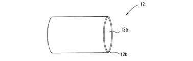
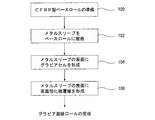
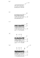
- FIG. 1 is a perspective explanatory view showing a state in which a metal sleeve is fitted to a CFRP base roll in the first embodiment of a gravure plate roll of the present invention. It is a flowchart which shows the process order of the manufacturing method of 1st Embodiment of the gravure printing roll of this invention.
- the gravure plate making roll 10 of the first embodiment of the present invention includes a CFRP base roll 12 and a cylindrical metal sleeve 14 fitted on the base roll 12. It is configured.
- the metal sleeve 14 include a nickel sleeve, a stainless sleeve, and an iron sleeve, and a nickel sleeve is preferable.
- the thickness of the CFRP base roll body 12b is not particularly limited, but for example, a thickness of about 1 cm to 5 cm is preferably used.
- the cylindrical metal sleeve 14 shown in FIG. 3 is known as described in Patent Documents 5 to 11, and those manufactured by a conventional method may be used.
- the metal sleeve 14 has a metal sleeve body 14b having a hollow portion 14a.
- the thickness of the metal sleeve body 14b is not particularly limited, but may be, for example, about 0.03 to 1 mm.
- a CFRP base roll 12 is used, and the metal sleeve 14 is detachably fitted to the CFRP base roll 12. It can be manufactured in a light weight and can be easily transported, has good dimensional stability against temperature changes, and is not affected by fluctuations in outside air temperature. Furthermore, once the gravure printing roll 10 of the present invention is purchased, if a new gravure printing roll is required, only a new design metal sleeve is purchased, and an old metal sleeve is removed from the base roll of the old gravure printing roll. By removing and fitting a new metal sleeve onto an old base roll, a gravure printing roll with a new pattern can be obtained.
- a manufacturing method of the first embodiment of the gravure printing roll of the present invention will be described with reference to FIGS.
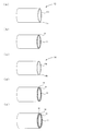
- a CFRP base roll 12 which is a hollow roll made of CFRP is prepared [Step 100 in FIG. 5, FIG. 6 (a) and FIG. 7 (a)].
- a cylindrical metal sleeve 14 is prepared [FIG. 6B]. The cylindrical metal sleeve 14 is fitted on the CFRP base roll 12 [Step 102 in FIG. 5, FIG. 6 (c) and FIG. 7 (b)].
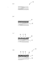
- the gravure cell 16 is formed by an etching method (a photosensitive solution is applied to the surface of the metal sleeve 14 and directly baked and then etched to form the gravure cell 16) or an electronic engraving method (with a diamond engraving needle by a digital signal).
- etching method a photosensitive solution is applied to the surface of the metal sleeve 14 and directly baked and then etched to form the gravure cell 16
- electronic engraving method with a diamond engraving needle by a digital signal.
- a known method such as mechanically engraving the gravure cell 16 on the surface of the metal sleeve 14 can be used.
- a surface reinforcing coating layer 18 is formed on the surface of the metal sleeve 14 (including the gravure cell 16 portion) on which the gravure cell 16 is formed [Step 106 in FIG. 5, FIG. 6 (d) and FIG. 7 (d)]. .
- CFRP has better dimensional stability against temperature changes than iron and aluminum, and is lighter than iron and aluminum, so it has better dimensional stability against temperature changes and can be easily transported.
- a CFRP tube 14 for a gravure printing roll is realized.
- the surface reinforcing coating layer 18 it is possible to apply a DLC coating layer, a silicon dioxide coating formed using a perhydropolysilazane solution as a raw material, and a conventionally well-known chromium plating as a surface reinforcing coating layer of a gravure printing roll.
- a coating layer can also be applied.
- a conventional chromium plating method may be applied to form the chromium plating coating layer.
- a method for forming the DLC coating layer known methods such as sputtering, vacuum deposition (electron beam), ion plating, MBE (molecular beam epitaxy), laser ablation, ion assist, and plasma CVD are known. Although a method can be applied, a sputtering method is preferable.
- a perhydropolysilazane coating layer is first formed on the surface of a metal sleeve.
- a perhydropolysilazane solution is prepared by dissolving perhydropolysilazane in a known solvent as described above, and this perhydropolysilazane solution is spray coated, inkjet coated, meniscus coated, It may be applied by tin coating, dip coating, spin coating, roll coating, wire bar coating, air knife coating, blade coating, curtain coating, or the like.
- the perhydropolysilazane coating layer is heated with superheated steam.
- the perhydropolysilazane coating layer becomes a silicon dioxide coating.
- the temperature of the superheated steam is 100 ° C. to 300 ° C., but heating over 200 ° C. causes deterioration of the CFRP base roll, and is preferably 100 ° C. to 200 ° C.
- the heat treatment with the superheated steam may be a single-stage treatment, but is preferably a multi-stage heat treatment including a primary heat treatment and a secondary heat treatment, and the conditions of the primary heat treatment are 105 ° C. to 170 ° C. 1 minute to 30 minutes, and the conditions of the secondary heat treatment are 140 ° C. to 200 ° C. and 1 minute to 30 minutes, and the temperature of the secondary heat treatment is set higher than the temperature of the primary heat treatment. Is preferred.
- reference numeral 11 denotes a gravure printing roll according to the second embodiment of the present invention.
- the gravure printing roll 11 according to the second embodiment of the present invention is similar to the gravure printing roll 10 according to the first embodiment shown in FIGS.
- a cushion layer 13 is formed on the surface of the base roll 12
- the present embodiment is different from the gravure plate making roll 10 of the first embodiment of the present invention in that the cylindrical metal sleeve 14 is fitted on the surface of the cushion layer 13.
- the base roll 12 and the metal sleeve 14 used in the gravure printing roll 11 of the second embodiment of the present invention are the same as those of the gravure printing roll of the first embodiment of the present invention, the explanation will be repeated. Omitted.
- the cushion layer 13 a synthetic rubber such as silicon rubber, or a synthetic resin having elasticity such as polyurethane or polystyrene can be used.
- the thickness of the cushion layer is not particularly limited as long as it can provide cushioning properties, that is, elasticity, but for example, a thickness of about 1 cm to 5 cm is sufficient.
- the gravure printing roll 11 of the second embodiment of the present invention can achieve the same effects as the gravure printing roll 10 of the first embodiment, but the gravure of the second embodiment. Since the plate-making roll 11 is provided with the cushion layer 13, the surface of the gravure plate-making roll 11 has cushioning properties, that is, elasticity, and the printing object is subjected to gravure printing on the surface of a hard and brittle material such as a glass plate. In this case, there is a great advantage that printing can be performed without damaging the surface of the printing object.
- a CFRP base roll 12 which is a hollow roll made of CFRP is prepared [Step 100 in FIG. 10, FIG. 11 (a) and FIG. 12 (a)].
- the cushion layer 13 is formed on the surface of the base roll 12 [Step 101 in FIG. 10 and FIG. 12 (b)].
- a cylindrical metal sleeve 14 is prepared [FIG. 11 (c)].
- the cylindrical metal sleeve 14 is fitted on the CFRP base roll 12 [Step 102 in FIG. 10, FIG. 11 (d) and FIG. 12 (c)].
- the gravure cell 16 can be formed by a known method such as an etching method or an electronic engraving method.
- a surface reinforcing coating layer 18 is formed on the surface of the metal sleeve 14 (including the gravure cell 16 portion) on which the gravure cell 16 is formed [Step 106 in FIG. 10, FIG. 11 (e) and FIG. 12 (e)]. .
- the gravure plate making roll 11 according to the second embodiment of the present invention is completed.
Landscapes
- Chemical & Material Sciences (AREA)
- Engineering & Computer Science (AREA)
- Ceramic Engineering (AREA)
- Inorganic Chemistry (AREA)
- Health & Medical Sciences (AREA)
- General Health & Medical Sciences (AREA)
- Toxicology (AREA)
- Printing Plates And Materials Therefor (AREA)
- Manufacture Or Reproduction Of Printing Formes (AREA)
Applications Claiming Priority (2)
| Application Number | Priority Date | Filing Date | Title |
|---|---|---|---|
| JP2009-097099 | 2009-04-13 | ||
| JP2009097099A JP2010247375A (ja) | 2009-04-13 | 2009-04-13 | グラビア製版ロール及びその製造方法 |
Publications (1)
| Publication Number | Publication Date |
|---|---|
| WO2010119831A1 true WO2010119831A1 (ja) | 2010-10-21 |
Family
ID=42982493
Family Applications (1)
| Application Number | Title | Priority Date | Filing Date |
|---|---|---|---|
| PCT/JP2010/056513 Ceased WO2010119831A1 (ja) | 2009-04-13 | 2010-04-12 | グラビア製版ロール及びその製造方法 |
Country Status (2)
| Country | Link |
|---|---|
| JP (1) | JP2010247375A (https=) |
| WO (1) | WO2010119831A1 (https=) |
Cited By (4)
| Publication number | Priority date | Publication date | Assignee | Title |
|---|---|---|---|---|
| CN102514355A (zh) * | 2011-11-25 | 2012-06-27 | 郑州运城制版有限公司 | 电镀电雕制作防伪版的方法 |
| WO2013176029A1 (ja) * | 2012-05-25 | 2013-11-28 | 株式会社シンク・ラボラトリー | パターン付ロール及びその製造方法 |
| WO2019077918A1 (ja) * | 2017-10-18 | 2019-04-25 | 株式会社シンク・ラボラトリー | グラビア印刷用シームレススリーブ |
| CN115515792A (zh) * | 2020-05-12 | 2022-12-23 | 株式会社村田制作所 | 凹版印刷用版辊、凹版印刷装置以及层叠陶瓷电容器的制造方法 |
Families Citing this family (2)
| Publication number | Priority date | Publication date | Assignee | Title |
|---|---|---|---|---|
| WO2019035501A1 (ko) * | 2017-08-18 | 2019-02-21 | (주)프로템 | 인쇄전자용 그라비어 옵셋롤 및 미세패턴 제조방법 |
| JP7047169B1 (ja) | 2021-06-11 | 2022-04-04 | 三菱ケミカル株式会社 | ロールの製造方法及びロール |
Citations (11)
| Publication number | Priority date | Publication date | Assignee | Title |
|---|---|---|---|---|
| JPS5434902A (en) * | 1977-08-23 | 1979-03-14 | Matsushita Electric Industrial Co Ltd | Cylindrical elastic gravure plate |
| JPS61177293A (ja) * | 1985-02-04 | 1986-08-08 | Toyo Ink Mfg Co Ltd | グラビア印刷版シリンダ |
| JPS62282934A (ja) * | 1985-03-29 | 1987-12-08 | ザウア−エツシツヒ・ウント・コ− | 輪転グラビア印刷シリンダ |
| JPS6467341A (en) * | 1987-06-19 | 1989-03-14 | Zauaaetsushitsuhi & Co | Gravure cylinder |
| JPH05193097A (ja) * | 1992-01-21 | 1993-08-03 | Nitto Denko Corp | グラビア用印刷ロール |
| JPH09207308A (ja) * | 1996-01-31 | 1997-08-12 | Polywest Kunststofftechnik Saueressig & Partner Gmbh & Co Kg | フレキソ印刷またはグラビア印刷ロール用スリーブ、その製造方法、およびその製造装置の作動方法 |
| JPH11314470A (ja) * | 1998-05-02 | 1999-11-16 | Think Laboratory Co Ltd | クッション性を有する凹版 |
| JP2002046250A (ja) * | 2000-08-03 | 2002-02-12 | Roll Tech Kk | 印刷版胴用スリーブロール |
| JP2003512204A (ja) * | 1999-10-18 | 2003-04-02 | ストルク・スクリーンズ・ベー・ヴエー | 繊維強化プラスチック材料から作られた薄壁シリンダ |
| JP2007118593A (ja) * | 2005-09-30 | 2007-05-17 | Think Laboratory Co Ltd | クッション層付グラビア製版ロール及びその製造方法 |
| WO2007132734A1 (ja) * | 2006-05-11 | 2007-11-22 | Think Laboratory Co., Ltd. | グラビア製版ロール及びその製造方法 |
-
2009
- 2009-04-13 JP JP2009097099A patent/JP2010247375A/ja active Pending
-
2010
- 2010-04-12 WO PCT/JP2010/056513 patent/WO2010119831A1/ja not_active Ceased
Patent Citations (11)
| Publication number | Priority date | Publication date | Assignee | Title |
|---|---|---|---|---|
| JPS5434902A (en) * | 1977-08-23 | 1979-03-14 | Matsushita Electric Industrial Co Ltd | Cylindrical elastic gravure plate |
| JPS61177293A (ja) * | 1985-02-04 | 1986-08-08 | Toyo Ink Mfg Co Ltd | グラビア印刷版シリンダ |
| JPS62282934A (ja) * | 1985-03-29 | 1987-12-08 | ザウア−エツシツヒ・ウント・コ− | 輪転グラビア印刷シリンダ |
| JPS6467341A (en) * | 1987-06-19 | 1989-03-14 | Zauaaetsushitsuhi & Co | Gravure cylinder |
| JPH05193097A (ja) * | 1992-01-21 | 1993-08-03 | Nitto Denko Corp | グラビア用印刷ロール |
| JPH09207308A (ja) * | 1996-01-31 | 1997-08-12 | Polywest Kunststofftechnik Saueressig & Partner Gmbh & Co Kg | フレキソ印刷またはグラビア印刷ロール用スリーブ、その製造方法、およびその製造装置の作動方法 |
| JPH11314470A (ja) * | 1998-05-02 | 1999-11-16 | Think Laboratory Co Ltd | クッション性を有する凹版 |
| JP2003512204A (ja) * | 1999-10-18 | 2003-04-02 | ストルク・スクリーンズ・ベー・ヴエー | 繊維強化プラスチック材料から作られた薄壁シリンダ |
| JP2002046250A (ja) * | 2000-08-03 | 2002-02-12 | Roll Tech Kk | 印刷版胴用スリーブロール |
| JP2007118593A (ja) * | 2005-09-30 | 2007-05-17 | Think Laboratory Co Ltd | クッション層付グラビア製版ロール及びその製造方法 |
| WO2007132734A1 (ja) * | 2006-05-11 | 2007-11-22 | Think Laboratory Co., Ltd. | グラビア製版ロール及びその製造方法 |
Cited By (6)
| Publication number | Priority date | Publication date | Assignee | Title |
|---|---|---|---|---|
| CN102514355A (zh) * | 2011-11-25 | 2012-06-27 | 郑州运城制版有限公司 | 电镀电雕制作防伪版的方法 |
| WO2013176029A1 (ja) * | 2012-05-25 | 2013-11-28 | 株式会社シンク・ラボラトリー | パターン付ロール及びその製造方法 |
| JPWO2013176029A1 (ja) * | 2012-05-25 | 2016-01-12 | 株式会社シンク・ラボラトリー | パターン付ロール及びその製造方法 |
| WO2019077918A1 (ja) * | 2017-10-18 | 2019-04-25 | 株式会社シンク・ラボラトリー | グラビア印刷用シームレススリーブ |
| JPWO2019077918A1 (ja) * | 2017-10-18 | 2020-09-17 | 株式会社シンク・ラボラトリー | グラビア印刷用シームレススリーブ |
| CN115515792A (zh) * | 2020-05-12 | 2022-12-23 | 株式会社村田制作所 | 凹版印刷用版辊、凹版印刷装置以及层叠陶瓷电容器的制造方法 |
Also Published As
| Publication number | Publication date |
|---|---|
| JP2010247375A (ja) | 2010-11-04 |
Similar Documents
| Publication | Publication Date | Title |
|---|---|---|
| WO2010119831A1 (ja) | グラビア製版ロール及びその製造方法 | |
| EP0273552B2 (en) | Method of making mandrels for use in a deposition process | |
| KR101444604B1 (ko) | 클리쉐 및 이를 포함하는 인쇄 장치 | |
| JP5173372B2 (ja) | 炭素繊維強化樹脂製中空ロール及びその製造方法並びに炭素繊維強化樹脂製グラビア製版ロール | |
| US20030143492A1 (en) | Mandrel with controlled release layer for multi-layer electroformed ink jet orifice plates | |
| US9194052B2 (en) | Method of fabricating a plurality of metallic microstructures | |
| JPWO2007013333A1 (ja) | グラビア製版ロール及びその製造方法 | |
| JPWO2007135901A1 (ja) | グラビア製版ロール及びその製造方法 | |
| JPWO2007135898A1 (ja) | グラビア製版ロールの全自動製造システム | |
| JPWO2007132734A1 (ja) | グラビア製版ロール及びその製造方法 | |
| US9506143B2 (en) | Protective film and method for producing same | |
| CN107206825B (zh) | 凹印滚筒及其制造方法以及印刷物的制造方法 | |
| JPWO2007135900A1 (ja) | グラビア製版ロール及びその製造方法 | |
| JP5004362B2 (ja) | グラビア製版ロールの全自動製造システム | |
| KR20080039936A (ko) | 쿠션층을 갖는 그라비아제판 롤 및 그의 제조방법 | |
| JP2018035014A (ja) | ペリクルの製造方法 | |
| JPWO2008133263A1 (ja) | 円筒状スクリーン版及びその製造方法 | |
| TWI761603B (zh) | 凹版印刷用無接縫套筒之製造方法 | |
| EP3357693A1 (en) | Center drum type gravure printing apparatus, and gravure printing method and method for manufacturing printed article using said apparatus | |
| US11499242B2 (en) | Method for producing a metal decoration on a dial and dial obtained according to this method | |
| JP4859921B2 (ja) | グラビア製版ロール及びその製造方法 | |
| EP1971490B1 (en) | Coated print roll and method therefor | |
| JP4968856B2 (ja) | 硬質被膜形成方法及びグラビア製版ロールの製造方法 | |
| US20180111365A1 (en) | Reimageable and reusable printing sleeve for a variable cutoff printing press | |
| JP2009226876A (ja) | スリーブ印刷版及びスリーブ印刷版の製造方法 |
Legal Events
| Date | Code | Title | Description |
|---|---|---|---|
| 121 | Ep: the epo has been informed by wipo that ep was designated in this application |
Ref document number: 10764415 Country of ref document: EP Kind code of ref document: A1 |
|
| NENP | Non-entry into the national phase |
Ref country code: DE |
|
| 122 | Ep: pct application non-entry in european phase |
Ref document number: 10764415 Country of ref document: EP Kind code of ref document: A1 |