WO2010119743A1 - 太陽電池ユニット - Google Patents
太陽電池ユニット Download PDFInfo
- Publication number
- WO2010119743A1 WO2010119743A1 PCT/JP2010/054400 JP2010054400W WO2010119743A1 WO 2010119743 A1 WO2010119743 A1 WO 2010119743A1 JP 2010054400 W JP2010054400 W JP 2010054400W WO 2010119743 A1 WO2010119743 A1 WO 2010119743A1
- Authority
- WO
- WIPO (PCT)
- Prior art keywords
- solar cell
- frame member
- fitting portion
- cell module
- fitting
- Prior art date
- Legal status (The legal status is an assumption and is not a legal conclusion. Google has not performed a legal analysis and makes no representation as to the accuracy of the status listed.)
- Ceased
Links
Images


Classifications
-
- F—MECHANICAL ENGINEERING; LIGHTING; HEATING; WEAPONS; BLASTING
- F24—HEATING; RANGES; VENTILATING
- F24S—SOLAR HEAT COLLECTORS; SOLAR HEAT SYSTEMS
- F24S40/00—Safety or protection arrangements of solar heat collectors; Preventing malfunction of solar heat collectors
- F24S40/40—Preventing corrosion; Protecting against dirt or contamination
- F24S40/44—Draining rainwater or condensation
-
- F—MECHANICAL ENGINEERING; LIGHTING; HEATING; WEAPONS; BLASTING
- F24—HEATING; RANGES; VENTILATING
- F24S—SOLAR HEAT COLLECTORS; SOLAR HEAT SYSTEMS
- F24S25/00—Arrangement of stationary mountings or supports for solar heat collector modules
- F24S25/20—Peripheral frames for modules
-
- F—MECHANICAL ENGINEERING; LIGHTING; HEATING; WEAPONS; BLASTING
- F24—HEATING; RANGES; VENTILATING
- F24S—SOLAR HEAT COLLECTORS; SOLAR HEAT SYSTEMS
- F24S25/00—Arrangement of stationary mountings or supports for solar heat collector modules
- F24S25/60—Fixation means, e.g. fasteners, specially adapted for supporting solar heat collector modules
- F24S25/67—Fixation means, e.g. fasteners, specially adapted for supporting solar heat collector modules for coupling adjacent modules or their peripheral frames
-
- F—MECHANICAL ENGINEERING; LIGHTING; HEATING; WEAPONS; BLASTING
- F24—HEATING; RANGES; VENTILATING
- F24S—SOLAR HEAT COLLECTORS; SOLAR HEAT SYSTEMS
- F24S20/00—Solar heat collectors specially adapted for particular uses or environments
- F24S2020/10—Solar modules layout; Modular arrangements
- F24S2020/12—Coplanar arrangements with frame overlapping portions
-
- F—MECHANICAL ENGINEERING; LIGHTING; HEATING; WEAPONS; BLASTING
- F24—HEATING; RANGES; VENTILATING
- F24S—SOLAR HEAT COLLECTORS; SOLAR HEAT SYSTEMS
- F24S25/00—Arrangement of stationary mountings or supports for solar heat collector modules
- F24S2025/01—Special support components; Methods of use
- F24S2025/022—Sealing means between support elements, e.g. overlapping arrangements; Gap closing arrangements
-
- Y—GENERAL TAGGING OF NEW TECHNOLOGICAL DEVELOPMENTS; GENERAL TAGGING OF CROSS-SECTIONAL TECHNOLOGIES SPANNING OVER SEVERAL SECTIONS OF THE IPC; TECHNICAL SUBJECTS COVERED BY FORMER USPC CROSS-REFERENCE ART COLLECTIONS [XRACs] AND DIGESTS
- Y02—TECHNOLOGIES OR APPLICATIONS FOR MITIGATION OR ADAPTATION AGAINST CLIMATE CHANGE
- Y02B—CLIMATE CHANGE MITIGATION TECHNOLOGIES RELATED TO BUILDINGS, e.g. HOUSING, HOUSE APPLIANCES OR RELATED END-USER APPLICATIONS
- Y02B10/00—Integration of renewable energy sources in buildings
- Y02B10/10—Photovoltaic [PV]
-
- Y—GENERAL TAGGING OF NEW TECHNOLOGICAL DEVELOPMENTS; GENERAL TAGGING OF CROSS-SECTIONAL TECHNOLOGIES SPANNING OVER SEVERAL SECTIONS OF THE IPC; TECHNICAL SUBJECTS COVERED BY FORMER USPC CROSS-REFERENCE ART COLLECTIONS [XRACs] AND DIGESTS
- Y02—TECHNOLOGIES OR APPLICATIONS FOR MITIGATION OR ADAPTATION AGAINST CLIMATE CHANGE
- Y02E—REDUCTION OF GREENHOUSE GAS [GHG] EMISSIONS, RELATED TO ENERGY GENERATION, TRANSMISSION OR DISTRIBUTION
- Y02E10/00—Energy generation through renewable energy sources
- Y02E10/40—Solar thermal energy, e.g. solar towers
- Y02E10/47—Mountings or tracking
Definitions
- the present invention relates to a building material-integrated solar cell unit that includes a plurality of solar cell modules that directly convert light, for example, sunlight into electric power, and is configured in place of a roofing material, and particularly at a joint between adjacent solar cell modules. It is about waterproofing.
- This solar power generation system is a system constructed by a solar cell module composed of a solar cell panel and its accessory parts.
- electric power companies sometimes purchase surplus power from general consumers, and the demand is growing rapidly as a distributed power supply system in each home and office.
- demand for solar cell modules is expected as a leading power system for preventing global warming, and exports from Japan are also increasing.
- a building material-integrated solar cell unit configured by replacing a roof material with a plurality of solar cell modules arranged vertically and horizontally along an inclined surface such as a roof of a house has become widespread.
- waterproofing of joints between adjacent solar cell modules is important in order to prevent rainwater from entering the field of the house.
- Patent Document 1 As a technique for waterproofing joints between adjacent solar cell modules in this type of solar cell unit, for example, there is one described in Patent Document 1.
- the technique described in Patent Document 1 is configured to form two raindrops by forming a rainwater pool with a ceiling plate of a lower frame member and a projection plate of an upper frame member that are adjacent to each other along an inclination direction. It prevents water from entering the joints of the modules.
- the technique described in the conventional patent document 1 includes a first fitting portion that fits with the solar cell panel in the lower frame material and a second fitting portion that fits with the solar cell panel in the upper frame material. A rainwater pool is formed between them. For this reason, there is a problem in that the distance between the solar cell panels in two solar cell modules adjacent to each other along the inclination direction becomes longer, the solar cell unit becomes larger, and the area necessary for installation increases.
- an object of the present invention is to provide a solar cell unit capable of preventing water from entering the joint between two adjacent solar cell modules and reducing the area required for installation. It is in.
- the solar cell unit of the present invention is disposed in the tilt direction along the mounting surface tilted with respect to the horizontal and in the lateral direction perpendicular to the tilt direction.
- a plurality of solar cell modules includes a solar cell panel having a plurality of solar cells and formed in a rectangular flat plate shape, a first frame member, and a second frame member.
- the first frame member includes a first fitting portion that fits with an upper side that is located on the upper side in the tilt direction when the first frame member is disposed on the mounting surface among the four sides of the solar cell panel, and an upper surface of the first fitting portion. And a projecting portion protruding from the head.
- the 2nd frame material was inclined and formed in the direction which approaches a mounting surface from the 2nd fitting part which fits with the lower side facing the upper side of a solar cell panel, and the 2nd fitting part. And a cover part. And this cover part covers the projection part of the 1st frame material of the solar cell module arrange
- the protrusions provided on the first frame member and the cover portions provided on the second frame member enter the joint between two solar cell modules adjacent along the inclination direction. Can prevent water to run. Furthermore, since the 1st water flow path is formed in the upper surface part of the 1st fitting part of a 1st frame material, the distance of the solar cell panel of two solar cell modules adjacent along an inclination direction is shortened. be able to. As a result, the solar cell unit can be reduced in size, and the installation space can be reduced.
- FIG. 1 is a schematic view showing the solar cell unit of this example
- FIG. 2 is a plan view of the solar cell unit of this example.
- the solar cell unit 10 includes a plurality of solar cell modules 1 and a rubber gasket 2 showing a specific example of a water stop member.
- the plurality of solar cell modules 1 are arranged side by side in a tilt direction Y and a lateral direction X orthogonal to the tilt direction Y along a roof base plate M showing a specific example of the mounting surface.
- the rubber gasket 2 is engage
- FIGS. 3 is an exploded perspective view showing the solar cell unit of this example
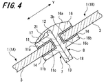
- FIGS. 4 and 5 are sectional views of the solar cell unit
- FIG. 6 is a plan view showing an enlarged main part of the solar cell unit of this example. is there.
- the solar cell module 1 includes a flat solar cell panel 3 and a frame member 6 surrounding the solar cell panel 3.
- the solar cell panel 3 is formed in a substantially rectangular flat plate shape.
- the upper side 3a located on one side that is the upper side in the inclination direction Y, the lower side 3b facing the upper side 3a, the upper side 3a, and the lower side 3b are substantially omitted. It has two sides 3c and 3c that are perpendicular.
- this solar cell panel 3 seals the several photovoltaic cell 5 formed in the rectangle with the sealing material between the surface protection members, such as the back surface protection member formed in flat form, and permeation
- a plurality of solar cells 5 are arranged side by side with the light receiving surface facing in the same direction.
- 54 solar cells 5 are provided.
- the 54 solar cells 5 are all connected in series via a wiring (not shown).
- a crystalline solar battery cell is used as the solar battery cell 5.
- the solar battery cell 5 used in this example is not limited to a crystalline solar battery cell, and is not limited to an amorphous solar battery cell or a mixed crystal / amorphous solar battery.
- a cell may be used.
- the number of the photovoltaic cells 5 which comprise a photovoltaic cell group is not limited to 54 sheets mentioned above, You may make it provide 53 sheets or less or 55 sheets or more.
- the solar battery cell 5 does not necessarily have to be a square shape, and may be formed in a substantially pentagonal shape or a circular shape.
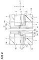
- a terminal box 4 is provided on the back surface of the solar cell panel 3 (see FIG. 5).
- the terminal box 4 contains a bypass diode. And this bypass diode is electrically connected with the several photovoltaic cell 5 via wiring. Further, two wiring cables 31 and 32 for output are drawn out from the terminal box 4.
- a positive terminal 33 is provided at the tip of the first wiring cable 31, and a negative terminal 34 is provided at the tip of the second wiring cable 32.
- the frame member 6 is attached to the upper side 3a, the lower side 3b and the two side sides 3c, 3c of the solar cell panel 3.
- the frame member 6 includes a first frame member 7, a second frame member 8, and two third frame members 9 and 9.
- a material of the first frame member 7, the second frame member 8, and the third frame member 9 for example, an aluminum alloy is preferable, but other metals can be used, or resin, wood, or the like is used. It may be used.
- the first frame member 7 is attached to the upper side 3 a of the solar cell panel 3. As shown in FIG. 4, the first frame member 7 includes a first fitting portion 11 that fits into the upper side 3 a of the solar cell panel 3, a projection portion 12, and a first flange portion 13. Has been.
- the first fitting portion 11 has a U-shaped cross section, and has an upper surface portion 11a, a bottom surface portion 11b facing the upper surface portion 11a, and a connection for connecting the upper surface portion 11a and the bottom surface portion 11b. And a surface portion 11c.
- the connection surface portion 11c is disposed on one end side in the inclination direction Y of the upper surface portion 11a and the bottom surface portion 11b.
- this 1st fitting part 11 has opened the other end side of the inclination direction Y in the upper-surface part 11a and the bottom face part 11b. From the opening side of the first fitting portion 11, the upper side 3 a of the solar cell panel 3 is inserted through the end surface sealing material 14. At this time, the upper surface portion 11 a is located on the light receiving surface side that is the front side of the solar cell panel 3, and the bottom surface portion 11 b is located on the back side of the solar cell panel 3.
- the protrusion part 12 is provided in the upper surface which is a surface on the opposite side to the surface which contacts the end surface sealing material 14 in the upper surface part 11a.
- the protrusion 12 is formed on one end side in the inclination direction Y on the upper surface of the upper surface portion 11a, that is, on the connection surface portion 11c side, and extends over substantially the entire longitudinal direction of the upper surface portion 11a. And this protrusion part 12 protrudes in the direction away
- the projection part 12 is formed in cross-sectional shape substantially square shape, it is not limited to this, You may form cross-sectional shape in a substantially triangular shape.
- a first flange portion 13 is provided on the bottom surface portion 11 b of the first fitting portion 11.
- the 1st flange part 13 protrudes in the direction which approaches the base plate M from the bottom face which is a surface on the opposite side to the surface which contacts the end surface sealing material 14 in the bottom face part 11b.
- the first flange portion 13 is formed on one end side in the inclination direction Y on the bottom surface of the bottom surface portion 11b, that is, on the connection surface portion 11c side, and extends over substantially the entire length of the bottom surface portion 11b.
- the second frame member 8 is attached to the lower side 3 b of the solar cell panel 3. As shown in FIG. 4, the second frame member 8 includes a second fitting portion 16 that fits on the lower side 3 b of the solar cell panel 3, a cover portion 17, and a second flange portion 18. Has been.
- the second fitting portion 16 has a U-shaped cross section, and has an upper surface portion 16a, a bottom surface portion 16b facing the upper surface portion 16a, and a connection for connecting the upper surface portion 16a and the bottom surface portion 16b. And a surface portion 16c.
- the connection surface portion 16c is disposed on the other end side in the inclination direction Y of the upper surface portion 16a and the bottom surface portion 16b.
- the second fitting portion 16 is open at one end side in the inclination direction Y of the upper surface portion 16a and the bottom surface portion 16b. From the opening side of the second fitting portion 16, the lower side 3 b of the solar cell panel 3 is inserted through the end surface sealing material 14. At this time, the upper surface portion 16 a is located on the light receiving surface side that is the front side of the solar cell panel 3, and the bottom surface portion 16 b is located on the back side of the solar cell panel 3.
- the upper surface which is a surface on the opposite side to the surface which contacts the end surface sealing material 14 in the upper surface part 16a is formed in circular arc shape, and approaches the solar cell panel 3 from the other end side of the inclination direction Y to one end side. Inclined in the direction. And the cover part 17 is continuously formed in this upper surface part 16a.
- the example which formed the upper surface in circular arc shape was demonstrated, it is not limited to this, You may form in linear form or making it incline.
- the cover part 17 protrudes from the upper surface part 16a toward the other side of the inclination direction Y and is inclined in a direction approaching the base plate M. As shown in FIGS. 3 and 6, notches 17a are formed at both ends of the cover portion 17 in the longitudinal direction. As shown in FIG. 4, the cover portion 17 covers the first frame member 7 and the protruding portion 12 in the solar cell module 1 disposed on the other side of the tilt direction Y, that is, the lower side. When the projection 12 is covered, the tip of the cover portion 17 comes into contact with the upper surface portion 11 a of the first fitting portion 11 in the first frame member 7. Thereby, the water which blows up from the lower side of the inclination direction Y can be prevented from entering between the first frame member 7 and the second frame member 8.
- the front end of the cover portion 17 may be set to an angle at which the cover portion 17 is fastened to the upper surface portion 11a, and the cover portion 17 may be brought into contact with the upper surface portion 11a.
- the present invention is not limited to this. is not. Even if a portion other than the tip of the cover portion 17 contacts the upper surface portion 11a of the first fitting portion 11, the purpose can be achieved.
- the 1st water flow path 21 is formed between the cover part 17 and the upper surface part 11a.
- the first water passage 21 extends along the lateral direction X.
- the water passage 21 is for draining the water W that has entered between the upper surface portion 11 a of the first frame member 7 and the cover portion 17 in the lateral direction X.
- the water W which flows through the 1st water flow path 21 is drained from the notch 17a provided in the both ends of the cover part 17 to the solar cell panel 3 side, and is drained to the other side of the inclination direction Y.
- notches 17a are not provided at both ends of the first water passage 21, water W may accumulate in the first water passage 21 and may freeze. Then, when the water W is frozen, the volume expands and the first frame member 7 and the second frame member 8 are deformed. As a result, even after the water W has melted, the first frame member 7 and the second frame member 8 are distorted, and the waterproof performance may be reduced.
- the notch 17a is provided at both ends of the cover portion 17, and the water W flowing through the first water passage 21 is drained to the solar cell panel 3 side, so that the water W becomes the first water passage 21. Can be prevented. It is possible to prevent the accumulated water W from freezing and deforming the first frame member 7 and the second frame member 8.
- the water W that has entered the first water passage 21 is formed between the first fitting portion 11 of the first frame member 7 and the second frame member 8 by the protrusions 12 provided on the first frame member 7. Intrusion between the second fitting portions 16 can be prevented.
- the joint drainage structure of the two solar cell modules 1A and 1B arranged along the tilt direction Y is the first of the first solar cell modules 1A disposed below the tilt direction Y. It is located on the upper surface part 11a of the fitting part 11. Therefore, as shown in FIG. 4, the second fitting in the second solar cell module 1 ⁇ / b> B disposed on the back surface of the first fitting portion 11 in the first solar cell module 1 ⁇ / b> A and the upper side in the tilt direction Y. The rear surface of the joint portion 16 can be brought into contact.
- the interval in the inclination direction Y between the solar cell panel 3 of the first solar cell module 1A and the solar cell panel 3 of the second solar cell module 1B can be reduced, and the solar cell unit 10 can be downsized. Can be planned. Thereby, the space required for installation of the solar cell unit 10 can be reduced.
- the second flange portion 18 is provided on the bottom surface portion 16 b of the second fitting portion 16.
- the second flange portion 18 protrudes in a direction approaching the base plate M from the bottom surface, which is the surface opposite to the surface in contact with the end surface sealing material 14 in the bottom surface portion 16b.
- the second flange portion 18 is formed on the connection surface portion 16c side of the bottom surface of the bottom surface portion 16b, and extends over substantially the entire length of the bottom surface portion 16b.
- the third frame member 9 is attached to a side 3 c that is substantially perpendicular to the upper side 3 a and the lower side 3 b among the four sides of the solar cell panel 3.
- the third frame member 9 includes a third fitting portion 22 that is fitted to the side 3c, a protruding portion 23, a leg portion 24, a leg portion 24, and a third fitting portion.
- the connecting portion 26 is connected to the joint portion 22.
- the third fitting portion 22 is formed in a U-shaped cross-section in the same manner as the first fitting portion 11 and the second fitting portion 16.
- the third fitting portion 22 includes an upper surface portion 22a, a bottom surface portion 22b that faces the upper surface portion 22a, and a connection surface portion 22c that connects the upper surface portion 22a and the bottom surface portion 22b.
- connection surface portion 22c of the third fitting portion 22 that is fitted to one side 3c of the lateral direction X in the solar cell panel 3 is disposed on one end side in the lateral direction X of the top surface portion 22a and the bottom surface portion 22b. ing.
- connection surface portion 22c of the third fitting portion 22 that is fitted to the other side 3c of the lateral direction X in the solar cell panel 3 is the other end in the lateral direction X of the top surface portion 22a and the bottom surface portion 22b. It is arranged on the side. Then, the side 3c of the solar cell panel 3 is inserted through the end surface sealing material 14 into the recess formed by the upper surface portion 22a, the bottom surface portion 22b, and the connection surface portion 22c.
- a notch 25 is formed on one end side in the longitudinal direction of the upper surface portion 22a, that is, one end side in the inclined direction Y. Further, a substantially flat projection 23 is continuously formed on the upper surface portion 22a.
- the protruding portion 23 protrudes in a direction away from the solar cell panel 3 from the upper surface portion 22a.
- the protruding portion 23 includes a protruding piece 23a and an inclined piece 23b.
- the protruding piece 23a is inclined in a direction away from the top plate 22a with respect to the base plate M.
- the inclined piece 23b is continuous from the protruding piece 23a and is inclined in a direction approaching the base plate M from the protruding piece 23a.
- connection portion 26 is provided so as to protrude from the bottom surface portion 22 b of the third fitting portion 22 toward the field plate M.
- the connection portion 26 is provided with a through hole 27 a through which the first wiring cable 31 and the second wiring cable 32 drawn out from the terminal box 4 pass.
- FIG. 7A and FIG. 7B are explanatory views showing the through hole 27a in an enlarged manner.
- the through hole 27a is formed in a substantially square shape.
- a fixing portion 27b is formed by cutting a part of the through hole 27a into a substantially circular shape.
- each of the two wiring cables 31 and 32 is provided with a contracting member 36. Examples of the material of the contracting member 36 include sponge and rubber.
- the contraction member 36 provided in the first wiring cable 31 is fitted into the fixed portion 27b in a contracted state. Thereby, the positive electrode terminal 33 and the negative electrode terminal 34 can be pulled out from the back surface side of the solar cell panel 3 to the outside of the third frame member 9.
- the fixing method of the 2nd wiring cable 32 is the same as the fixing method of the 1st wiring cable 31, the description is abbreviate
- the example which formed the through-hole 27a in the substantially square shape was demonstrated in this example, it is not limited to this, For example, you may form in other polygonal shapes, such as a hexagon, and circular shape.
- the fixing portion 27b is not limited to a substantially circular shape, and may be formed in a polygonal shape or other various shapes as long as the contraction members 36 of the two wiring cables 31 and 32 can be engaged.
- the leg part 24 is provided in the end of the connection part 26 on the opposite side to the bottom face part 22b.
- the leg portion 24 has a substantially trapezoidal cross-sectional shape, and is provided with a fixing hole 28 and an insertion hole 29. Further, the leg portion 24 is set so that the length in the lateral direction X is shorter than the protruding portion 23. Therefore, the leg portion 24 is hidden by the protruding portion 23 when the solar cell module 1 is viewed from the front side.
- the fixing hole 28 is formed in the inclined surface of the leg portion 24.
- a fixing screw 44 for fixing the solar cell module 1 to the base plate M is screwed into the fixing hole 28.
- the insertion hole 29 is formed on the surface of the leg portion 24 that comes into contact with the base plate M.
- the insertion hole 29 is a recess that is recessed in a substantially square shape.
- a grounding rod 38 is inserted into the insertion hole 29 of the leg portion 24.
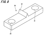
- FIG. 8 is a perspective view showing a ground bar
- FIG. 9 is a perspective view showing a state where the ground bar is attached to the solar cell module.
- the ground bar 38 is formed of a substantially rectangular parallelepiped conductive material.
- the ground bar 38 is provided with two fixing holes 39 and 41 and a positioning projection 42.
- the first fixing hole 39 is formed at one end portion in the longitudinal direction
- the second fixing hole 41 is formed at the other end portion in the longitudinal direction.
- the positioning protrusion 42 is disposed at the approximate center in the longitudinal direction of the ground bar 38.
- the positioning protrusion 42 is formed in a substantially triangular cross section, but may be formed in a quadrilateral shape or other shapes.
- the positioning protrusion 42 comes into contact with the third frame member 9 when the ground bar 38 is inserted into the insertion hole 29. Accordingly, the fixing hole 28 provided in the leg portion 24 of the third frame member 9 and the first fixing hole 39 or the second fixing hole 41 provided in the ground bar 38 can be positioned.
- the present invention is not limited to this, and the positioning protrusion 42 is disposed on one side or the other side in the longitudinal direction. May be.
- the frame member 6 and the grounding bar 38 are fixed by screwing the fixing hole 28 of the leg portion 24 and the first fixing hole 39 or the second fixing hole 41 of the grounding bar 38 with the fixing screw 44.
- the frame member 6 of the solar cell module 1 and the ground bar 38 are electrically connected via the fixing screw 44.
- the first fixing hole 39 side of the ground bar 38 is disposed on the lower side of the two solar cell modules 1 ⁇ / b> A and 1 ⁇ / b> B disposed along the inclination direction Y.
- the second fixing hole 41 side of the ground bar 38 is inserted into the insertion hole 29 of the second solar cell module 1B disposed on the upper side in the tilt direction Y.
- two solar cell modules 1A and 1B can be electrically connected by one earthing rod 38 and the fixing screw 44.
- the earth bar 38 has a role as a guide for positioning the first solar cell module 1A and the second solar cell module 1B in the tilt direction Y. Thereby, the joints in the inclination direction Y of the solar cell module 1 can be aligned, and the efficiency of the disposition work of the solar cell module 1 can be improved.
- ground bars 38 are attached to both sides of the two third frame members 9 . Of these, it may be attached to at least one side.
- the rubber gasket 2 has elasticity and includes a cover portion 46 and a fitting portion 47. And as shown in FIG. 2, the rubber gasket 2 is along the inclination direction Y so that the clearance gap formed between the two solar cell modules 1 and 1 arrange
- the rubber gasket 2 is arranged so as to cover substantially the entire third frame member 9 in the two solar cell modules 1A, 1C arranged along the lateral direction X. Established. Thereby, it can prevent that water penetrate
- the cover 46 is formed in a shape that covers substantially the entire protrusion 23 of the two solar cell modules 1A and 1C. When covering the protrusion 23, the cover 46 is inclined from approximately the center in the lateral direction X to both ends. Thereby, the water W can be drained to the solar cell panel 3 side without collecting the water W in the rubber gasket 2.
- the fitting portion 47 is provided on the surface of the cover portion 46 on the side opposite to the drainage surface side and at the approximate center in the lateral direction X.
- the fitting portion 47 is fitted between the protruding portion 23 of the first solar cell module 1A and the protruding portion 23 of the third solar cell module 1C.
- a second water passage 48 is formed between the projecting portion 23 and the rubber gasket 2.
- the second water passage 48 extends along the inclination direction Y.
- the cover part 46 of the rubber gasket 2 covers up to both ends of the first frame member 7 and the second frame member 8 in the lateral direction X.
- the first water passage 21 and the second water passage 48 communicate with each other with the third fitting portion 22 of the third frame member 9 interposed therebetween. Therefore, when the water W flowing through the first water passage 21 passes over the upper surface portion 22a of the third fitting portion 22 without flowing from the notch 17a to the solar battery panel 3 side, the second water passage 48 flows.
- the water-stopping member may be a gasket formed of, for example, an elastic resin.
- FIG. 10 is a plan view showing a connection state of positive and negative terminals in a plurality of solar cell modules.
- the wiring cables 31 and 32 are drawn out to one side in the horizontal direction X from the third frame member 9 disposed on one side in the horizontal direction X of the plurality of solar cell modules 1. Yes. And the positive electrode terminal 33 of the solar cell module 1 arrange
- the negative electrode terminal 34 of the solar cell module 1 disposed at one end in the tilt direction Y is disposed in the lateral direction X and the positive electrode terminal 33 of the solar cell module 1 disposed at the other end in the tilt direction Y.
- an extension cable (not shown).
- the plurality of solar cell modules 1 arranged along the inclination direction Y are all connected in series.
- the solar cell unit 10 does not need to connect all the solar cell modules 1 in series, and may divide the plurality of solar cell modules 1 into arbitrary numbers and connect them in series.
- FIGS. 9 and 10 a method for assembling the solar cell unit 10 having the above-described configuration will be described with reference to FIGS. 9 and 10.
- a plurality of solar cell modules 1 are arranged one by one along the inclination direction Y of the base plate M.
- the grounding rod 38 is inserted into the insertion hole 29 of the leg portion 24 of the first solar cell module 1 ⁇ / b> A disposed below the inclination direction Y.
- the grounding rod 38 is provided with a positioning projection 42. Therefore, it is possible to easily align the fixing holes 28 of the leg portions 24 of the first solar cell module 1A and the first fixing holes 39 of the ground bar 38. Further, it is possible to prevent the ground bar 38 from sliding down along the tilt direction Y.
- the first solar cell module 1A in which the ground bar 38 is inserted is fixed to the base plate M using the fixing screw 44. Thereby, the installation of the first solar cell module 1A is completed.
- the two wiring cables 31 and 32 penetrate through a through hole 27 a provided in the connection portion 26 of the third frame member 9.
- the fixing hole 28 is provided in the inclined surface of the leg part 24, a tool can be inserted without the protrusion part 23 getting in the way. As a result, it is possible to improve the efficiency of the fixing work of the solar cell module 1. Further, since the length of the leg portion 24 in the lateral direction X is set shorter than the protruding portion 23, the fixing screw 44 fixed to the leg portion 24 when the solar cell module 1 is viewed from the front side is projected. 23 can hide.
- the second solar cell module 1B located on the other side of the tilt direction Y, that is, on the upper side of the first solar cell module 1A is disposed.
- the second solar cell module 1B is arranged so that the ground bar 38 is inserted into the insertion hole 29 of the second solar cell module 1B.
- the cover portion 17 of the second solar cell module 1B covers the protrusion 12 of the first solar cell module 1A, and the tip of the cover portion 17 is the first solar cell module 1A.
- the first frame member 7 is approached. Thereby, the 1st water flow path 21 is formed between the cover part 17 and the upper surface part 11a of the 1st fitting part 11 in 1 A of 1st solar cell modules.
- the upper surface portion 16a in the second solar cell module 1B is formed in an arc shape, and is inclined in a direction approaching the solar cell panel 3 from the other end side to the one end side in the inclination direction Y.
- the 1st water flow path 21 was formed in the upper surface of the 1st fitting part 11, and the connection surface part 11c and the 2nd solar cell in the 1st fitting part 11 of 1 A of 1st solar cell modules are used.
- the connection surface part 16c in the 2nd fitting part 16 of the module 1B can be made to contact. Thereby, the space
- the second solar cell module 1B is fixed to the base plate M using the fixing screw 44.
- the first solar cell module 1A and the second solar cell module 1B are electrically connected via the ground bar 38.
- the ground bar 38 serves as a guide for arranging the second solar cell module 1B.
- the above-described procedure is repeated to arrange a plurality of solar cell modules 1 on the upper side of the inclination direction Y of the second solar cell module 1B, and form a row of solar cell modules 1 arranged along the inclination direction Y. That is, the solar cell module 1 is arranged from the eaves of the field board M toward the ridge.
- the third solar cell module 1C is disposed on one side of the lateral direction X of the first solar cell module 1A. And the row
- wiring cables 31 and 32 extending from the third frame member 9 of the plurality of solar cell modules 1 are connected.
- the positive electrode terminal 33 of the solar cell module 1 disposed on the upper side of the tilt direction Y and the negative electrode terminal 34 of the solar cell module 1 disposed on the lower side of the tilt direction Y are connected.
- the negative electrode terminal 34 of the solar cell module 1 disposed on the uppermost side in the tilt direction Y is disposed on one side of the horizontal direction X and on the lowermost side in the tilt direction Y.
- all the several solar cell modules 1 arranged along the inclination direction Y are connected in series.
- the contraction member 36 provided in the wiring cables 31 and 32 is contracted and fitted into the fixing portion 27b.
- connection between the positive electrode terminal 33 and the negative electrode terminal 34 can be performed between two rows of solar cell modules, wiring processing can be performed very easily with a wide field of view. As a result, confirmation such as half insertion of the positive electrode terminal 33 and the negative electrode terminal 34 can be reliably performed, and electrical connection failure can be reliably prevented. Further, even after the solar cell unit 10 is assembled, the rubber gasket 2 can be removed to perform maintenance etc. very easily.
- the rubber gasket 2 is fitted between the solar cell modules 1A and 1C arranged along the tilt direction.
- the inclined piece 23 b provided on the distal end side of the protruding portion 23 in the solar cell module 1 is inclined in a direction approaching the base plate M.
- the second water passage 48 is formed between the protrusion 23 and the rubber gasket 2 by fitting the rubber gasket 2 into the row of the two solar cell modules 1.
- the rubber gasket 2 can be fixed by fitting the fitting portions 47 of the rubber gasket 2 between the rows of the two solar cell modules 1 arranged in the lateral direction X. Therefore, the number of parts such as a fixing screw for fixing the water stop member can be reduced, and the efficiency of the attaching operation can be improved.
- the assembly method of the solar cell unit 10 is not limited to the method mentioned above, You may assemble by another method.
- the present invention is not limited to the embodiment described above and shown in the drawings, and various modifications can be made without departing from the scope of the invention described in the claims.
- the wiring cable may be pulled out from below the first frame member and the second frame member, and the positive electrode terminal and the negative electrode terminal may be connected on the back side of the solar cell module.
- the solar cell unit of this invention is arrange
- the solar cell unit of this invention is arrange
- SYMBOLS 1 Solar cell module, 1A ... 1st solar cell module, 1B ... 2nd solar cell module, 1C ... 3rd solar cell module, 2 ... Rubber gasket (water-stop member), 3 ... Solar cell panel, 3a ... upper side, 3b ... lower side, 3c ... side edge, 4 ... terminal box, 5 ... solar cell, 6 ... frame material, 7 ... first frame material, 8 ... second frame material, 9 ... third frame Materials: 10 ... solar cell unit, 11 ... first fitting part, 11a, 16a, 22a ... top face part, 11b, 16b, 22b ... bottom face part, 11c, 16c, 22c ... connection face part, 12 ...
Landscapes
- Engineering & Computer Science (AREA)
- Physics & Mathematics (AREA)
- Life Sciences & Earth Sciences (AREA)
- Sustainable Development (AREA)
- Sustainable Energy (AREA)
- Thermal Sciences (AREA)
- Chemical & Material Sciences (AREA)
- Combustion & Propulsion (AREA)
- Mechanical Engineering (AREA)
- General Engineering & Computer Science (AREA)
- Photovoltaic Devices (AREA)
- Roof Covering Using Slabs Or Stiff Sheets (AREA)
Applications Claiming Priority (2)
| Application Number | Priority Date | Filing Date | Title |
|---|---|---|---|
| JP2009097216A JP5137892B2 (ja) | 2009-04-13 | 2009-04-13 | 太陽電池ユニット |
| JP2009-097216 | 2009-04-13 |
Publications (1)
| Publication Number | Publication Date |
|---|---|
| WO2010119743A1 true WO2010119743A1 (ja) | 2010-10-21 |
Family
ID=42982410
Family Applications (1)
| Application Number | Title | Priority Date | Filing Date |
|---|---|---|---|
| PCT/JP2010/054400 Ceased WO2010119743A1 (ja) | 2009-04-13 | 2010-03-16 | 太陽電池ユニット |
Country Status (2)
| Country | Link |
|---|---|
| JP (1) | JP5137892B2 (https=) |
| WO (1) | WO2010119743A1 (https=) |
Cited By (2)
| Publication number | Priority date | Publication date | Assignee | Title |
|---|---|---|---|---|
| WO2014075746A1 (de) * | 2012-11-13 | 2014-05-22 | Habdank Pv-Montagesysteme Gmbh & Co. Kg | Montagesystem für solarmodule |
| WO2014082687A1 (de) * | 2012-11-29 | 2014-06-05 | Habdank Pv-Montagesysteme Gmbh & Co. Kg | Montagesystem für solarmodule |
Families Citing this family (4)
| Publication number | Priority date | Publication date | Assignee | Title |
|---|---|---|---|---|
| JP5857242B2 (ja) * | 2012-03-16 | 2016-02-10 | パナソニックIpマネジメント株式会社 | 太陽電池モジュール及びその設置構造 |
| KR20150041932A (ko) * | 2013-10-10 | 2015-04-20 | 엘지이노텍 주식회사 | 태양전지 모듈 |
| JP6368604B2 (ja) * | 2014-09-25 | 2018-08-01 | 株式会社カネカ | 太陽電池モジュール及び太陽電池モジュールの設置方法 |
| JP6486415B2 (ja) * | 2017-06-29 | 2019-03-20 | 連豐 薛 | 太陽電池屋根の改良構造 |
Citations (8)
| Publication number | Priority date | Publication date | Assignee | Title |
|---|---|---|---|---|
| JPS5977253A (ja) * | 1982-10-25 | 1984-05-02 | Hirai Giken:Kk | エネルギー収集屋根 |
| JPS6080648A (ja) * | 1983-10-07 | 1985-05-08 | 日本軽金属株式会社 | 屋根 |
| JPH06136895A (ja) * | 1992-10-27 | 1994-05-17 | Gantan Beauty Kogyo Kk | 太陽電池パネルの取付構造 |
| JPH06318729A (ja) * | 1993-05-10 | 1994-11-15 | Canon Inc | 太陽電池モジュールアレイ |
| JPH09195472A (ja) * | 1996-01-16 | 1997-07-29 | Misawa Homes Co Ltd | 太陽エネルギー変換パネルの継目の防水構造 |
| JP2000352163A (ja) * | 1999-06-09 | 2000-12-19 | Yokogawa Bridge Corp | 太陽電池パネルの取付構造 |
| JP2001329664A (ja) * | 2000-03-15 | 2001-11-30 | Kanegafuchi Chem Ind Co Ltd | 太陽電池モジュール、発電装置、発電装置設置方法、及び中間横架台 |
| JP2003056131A (ja) * | 2001-08-20 | 2003-02-26 | Kyocera Corp | 太陽エネルギー利用機器及び太陽エネルギー利用アレイ |
-
2009
- 2009-04-13 JP JP2009097216A patent/JP5137892B2/ja not_active Expired - Fee Related
-
2010
- 2010-03-16 WO PCT/JP2010/054400 patent/WO2010119743A1/ja not_active Ceased
Patent Citations (8)
| Publication number | Priority date | Publication date | Assignee | Title |
|---|---|---|---|---|
| JPS5977253A (ja) * | 1982-10-25 | 1984-05-02 | Hirai Giken:Kk | エネルギー収集屋根 |
| JPS6080648A (ja) * | 1983-10-07 | 1985-05-08 | 日本軽金属株式会社 | 屋根 |
| JPH06136895A (ja) * | 1992-10-27 | 1994-05-17 | Gantan Beauty Kogyo Kk | 太陽電池パネルの取付構造 |
| JPH06318729A (ja) * | 1993-05-10 | 1994-11-15 | Canon Inc | 太陽電池モジュールアレイ |
| JPH09195472A (ja) * | 1996-01-16 | 1997-07-29 | Misawa Homes Co Ltd | 太陽エネルギー変換パネルの継目の防水構造 |
| JP2000352163A (ja) * | 1999-06-09 | 2000-12-19 | Yokogawa Bridge Corp | 太陽電池パネルの取付構造 |
| JP2001329664A (ja) * | 2000-03-15 | 2001-11-30 | Kanegafuchi Chem Ind Co Ltd | 太陽電池モジュール、発電装置、発電装置設置方法、及び中間横架台 |
| JP2003056131A (ja) * | 2001-08-20 | 2003-02-26 | Kyocera Corp | 太陽エネルギー利用機器及び太陽エネルギー利用アレイ |
Cited By (2)
| Publication number | Priority date | Publication date | Assignee | Title |
|---|---|---|---|---|
| WO2014075746A1 (de) * | 2012-11-13 | 2014-05-22 | Habdank Pv-Montagesysteme Gmbh & Co. Kg | Montagesystem für solarmodule |
| WO2014082687A1 (de) * | 2012-11-29 | 2014-06-05 | Habdank Pv-Montagesysteme Gmbh & Co. Kg | Montagesystem für solarmodule |
Also Published As
| Publication number | Publication date |
|---|---|
| JP5137892B2 (ja) | 2013-02-06 |
| JP2010251418A (ja) | 2010-11-04 |
Similar Documents
| Publication | Publication Date | Title |
|---|---|---|
| CA2654764C (en) | Interconnected solar module design and system | |
| JP4661021B2 (ja) | 太陽電池モジュール、太陽電池モジュールの設置構造、及びその設置構造を有した発電機能付き屋根 | |
| EP1270842B1 (en) | Solar cell module and roof equipped with power generating function using it | |
| JP5137892B2 (ja) | 太陽電池ユニット | |
| US11418146B2 (en) | Electrical connection device for a photovoltaic system | |
| JP5574740B2 (ja) | 屋根構造、及び太陽電池モジュールの軒先取付け具 | |
| KR101797562B1 (ko) | 조립식 태양전지모듈 체결장치를 구비한 지붕 구조물 | |
| JP3652165B2 (ja) | 太陽電池モジュールの取付け構造およびその取付け方法 | |
| JP5131527B2 (ja) | 太陽電池の屋根上への設置構造及び設置工法 | |
| JP2010251420A (ja) | 太陽電池モジュール、及び太陽電池ユニット | |
| JP2010251419A (ja) | 太陽電池ユニット | |
| JP4351567B2 (ja) | 太陽光発電装置 | |
| JP5574739B2 (ja) | 屋根構造、太陽電池モジュールの取付け具及び太陽電池モジュールの取付け方法 | |
| JP2017204920A (ja) | 太陽電池モジュール | |
| JP5557548B2 (ja) | 屋根構造 | |
| JP2010177631A (ja) | 太陽電池モジュール | |
| JP2006009514A (ja) | 板金屋根部材および太陽光発電システム | |
| CN118920981B (zh) | 护板组装结构、外框组件及光伏瓦 | |
| JP4713004B2 (ja) | 太陽電池一体型パネル | |
| JP3942322B2 (ja) | 太陽電池モジュール及び屋根 | |
| JP6594626B2 (ja) | 屋根構造 | |
| JP5574741B2 (ja) | 屋根構造、太陽電池モジュールの取付け具及び太陽電池モジュールの取付け方法 | |
| JP5356276B2 (ja) | 屋根構造、太陽電池モジュールの取付け具及び太陽電池モジュールの取付け方法 | |
| JP2017203277A (ja) | 太陽電池モジュールの接地構造、太陽電池モジュール、並びに太陽電池モジュールの接地方法 | |
| JP2017203278A (ja) | 太陽電池モジュールの配置構造及び屋根構造 |
Legal Events
| Date | Code | Title | Description |
|---|---|---|---|
| 121 | Ep: the epo has been informed by wipo that ep was designated in this application |
Ref document number: 10764329 Country of ref document: EP Kind code of ref document: A1 |
|
| DPE1 | Request for preliminary examination filed after expiration of 19th month from priority date (pct application filed from 20040101) | ||
| NENP | Non-entry into the national phase |
Ref country code: DE |
|
| 122 | Ep: pct application non-entry in european phase |
Ref document number: 10764329 Country of ref document: EP Kind code of ref document: A1 |