WO2010117045A1 - 自動分析装置 - Google Patents
自動分析装置 Download PDFInfo
- Publication number
- WO2010117045A1 WO2010117045A1 PCT/JP2010/056397 JP2010056397W WO2010117045A1 WO 2010117045 A1 WO2010117045 A1 WO 2010117045A1 JP 2010056397 W JP2010056397 W JP 2010056397W WO 2010117045 A1 WO2010117045 A1 WO 2010117045A1
- Authority
- WO
- WIPO (PCT)
- Prior art keywords
- sample
- cycle
- reagent
- dispensing
- inspection
- Prior art date
- Legal status (The legal status is an assumption and is not a legal conclusion. Google has not performed a legal analysis and makes no representation as to the accuracy of the status listed.)
- Ceased
Links
Images










Classifications
-
- G—PHYSICS
- G01—MEASURING; TESTING
- G01N—INVESTIGATING OR ANALYSING MATERIALS BY DETERMINING THEIR CHEMICAL OR PHYSICAL PROPERTIES
- G01N35/00—Automatic analysis not limited to methods or materials provided for in any single one of groups G01N1/00 - G01N33/00; Handling materials therefor
- G01N35/02—Automatic analysis not limited to methods or materials provided for in any single one of groups G01N1/00 - G01N33/00; Handling materials therefor using a plurality of sample containers moved by a conveyor system past one or more treatment or analysis stations
- G01N35/025—Automatic analysis not limited to methods or materials provided for in any single one of groups G01N1/00 - G01N33/00; Handling materials therefor using a plurality of sample containers moved by a conveyor system past one or more treatment or analysis stations having a carousel or turntable for reaction cells or cuvettes
-
- G—PHYSICS
- G01—MEASURING; TESTING
- G01N—INVESTIGATING OR ANALYSING MATERIALS BY DETERMINING THEIR CHEMICAL OR PHYSICAL PROPERTIES
- G01N35/00—Automatic analysis not limited to methods or materials provided for in any single one of groups G01N1/00 - G01N33/00; Handling materials therefor
- G01N35/00584—Control arrangements for automatic analysers
- G01N35/0092—Scheduling
Definitions
- the present invention relates to an automatic analyzer that automatically analyzes components such as blood, and is particularly effective when applied to an apparatus that performs a plurality of test items such as biochemical tests, immune serum tests, and blood coagulation tests.
- Clinical tests require various pretreatments such as centrifugation, hemolysis, and B / F separation of antigen-antibody reactions in immune serum tests. These pretreatments are often not performed in the automatic analyzer that actually performs the inspection, but are performed in advance by a dedicated device.
- a specimen transport system is well known as an apparatus for performing pretreatment in advance.
- a pre-processing unit and a plurality of analyzers are connected by a belt conveyor, and a sample set on a rack on the belt conveyor is transported to a target pre-processing unit or analyzer.
- a system that automates and processes all the tests performed in such clinical laboratories is introduced, enormous costs are required, which cannot be performed in a general hospital or the like.
- B / F separation, hemolysis, etc. are realized by the pre-processing mechanism in the device.
- a device to which a B / F separation function is added generally has problems such as a complicated mechanism, a large device size, and a low processing capability.
- each test is performed separately, and multiple tasks such as sample movement between devices, sample setting to the device, analysis request operation, and summary of output results are interlaced, resulting in efficiency. Is also bad.
- Patent Document 1 proposes an apparatus including a first test mechanism that performs biochemical and immune serum tests and a second test mechanism that performs immunocoagulation tests.
- Patent Document 2 proposes an inspection method in which a number of reaction vessels are sequentially moved by a frame advance operation, and light intensity is calculated at a photometric interval corresponding to each sample during a reciprocating operation. Furthermore, in recent years, apparatuses having a plurality of inspection mechanisms and having a preprocessing function and the like are commercially available.
- the disk on which the container is arranged operates as one rotation + 1 container or half rotation + 1 container in one cycle.
- the stop position of the container moves by one container.
- the sample is dispensed, the diluent is dispensed, and agitation is performed in the container, and the sample is diluted inside the container.
- the diluted container is moved to a position for redispensing the sample.
- sampling sample dispensing
- a reagent probe carryover provided in the reagent dispensing mechanism occurs in the subsequent analysis process, it is necessary to add an operation for washing after the operation of the reagent probe. Furthermore, the operation timing of the reagent dispensing mechanism may overlap with the inspection of a plurality of items. Even in these cases, the processing capacity of the apparatus is reduced.
- Sample preprocessing includes items that have no limitation on processing time and items that need to be constant.
- a test item such as an enzyme or protein
- the sample need only be diluted at a constant magnification for simple dilution.
- HbA1c which is a blood cell component in blood
- HbA1c which is a blood cell component in blood
- the analysis principle and analysis cycle are different for each test item Since the analysis principle is different for each test item, the reaction time is also different. For example, biochemical and blood coagulation tests measure multiple times at regular intervals during the reaction, whereas immunoserum tests only measure after a certain period of time and do not measure during the reaction. In addition, since the analysis cycles are different, the control is complicated to perform a plurality of inspections with one apparatus, and efficient processing cannot be performed.
- An object of the present invention is to provide an automatic analyzer that can efficiently perform inspection of a plurality of items while aligning the timing of sample dispensing and simplifying the apparatus configuration.
- the automatic analyzer of the present invention comprises a disk in which an intermediate container for performing a pretreatment of a sample dispensed from within a sample container with a pretreatment liquid or a reaction between the sample and a reagent is disposed;
- An automatic analyzer having a plurality of inspection mechanisms for the sample dispensed from within the intermediate container, wherein the sample is dispensed from the sample container or from the intermediate container to the plurality of inspection mechanisms.
- the operation cycle time is n times the minimum operation cycle time of each inspection item (n is an integer or an intermediate value between integers).
- the dispensing operation cycle time of the sample from the sample container or the intermediate container to the plurality of inspection mechanisms is n times the minimum operation cycle time of each inspection item (n is an integer or Since it is an intermediate value between integers, it is possible to align the sample dispensing timing in consideration of a plurality of conditions such as the operation of the entire apparatus and the reaction time of each inspection. In other words, it is efficient so that items with a short analysis cycle can be inspected during inspection of items with a long analysis cycle, and items with a large number of requests can be inspected between items with a small number of requests.
- the timing of sample dispensing can be aligned. Thereby, the inspection of a plurality of items can be performed efficiently while aligning the sample dispensing timing and simplifying the apparatus configuration.
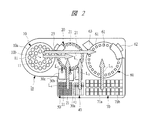
- FIG. (A)-(c) It is a schematic plan view which shows the outline of one Embodiment of the automatic analyzer of this invention. It is a figure which shows the flow of the sample, pretreatment liquid, reagent, etc. in the automatic analyzer of FIG. (A)-(c) is explanatory drawing explaining the example of the flow of operation
- movement in the automatic analyzer of FIG. (A)-(c) is explanatory drawing explaining the example of the flow of operation
- movement in the automatic analyzer of FIG. (A)-(c) is explanatory drawing explaining the example of the flow of operation
- (A)-(c) is a flowchart which shows the flow of priority determination.
- (A)-(c) is explanatory drawing explaining the example of the operation
- FIG. 1 is a schematic plan view showing an outline of an embodiment of the automatic analyzer of the present invention
- FIG. 2 is a diagram showing the flow of samples, pretreatment liquids, reagents and the like in the automatic analyzer of FIG.
- FIGS. 3A to 3C, FIGS. 4A to 4C, and FIGS. 5A to 5C are explanatory diagrams for explaining an example of the flow of operations in the automatic analyzer of FIG. 1 in this order. It is.
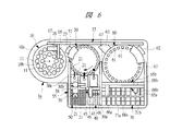
- FIG. 6 is an explanatory diagram for explaining another example of the operation flow in the automatic analyzer of FIG. In FIG. 2, the sample dispensing mechanism is not shown for the sake of understanding.
- the illustration of the control unit that controls the entire automatic analyzer, the display unit for analysis data, the input unit, and the storage unit is omitted.
- the automatic analyzer 1a includes a sample disk 10, an intermediate disk (disk) 20, and a reaction disk (inspection mechanism) 60 in this order along the longitudinal direction of the apparatus.
- Flow system analysis mechanisms (inspection mechanisms) 30a to 30c are provided on the front side of the intermediate disk 20, and a pretreatment liquid and a flow system analysis reagent are further provided on the front side of the flow system analysis mechanisms 30a to 30c.
- a container storage section (hereinafter referred to as “pretreatment liquid container storage section”) 40 and a disposable container storage section 50 are provided.
- a biochemical test reagent cassette 70 is provided on the front side of the reaction disk 60.
- the sample dispensing mechanism 15 is provided between the sample disk 10 and the reaction disk 60.
- the pretreatment liquid and flow system analysis reagent dispensing mechanism (hereinafter referred to as “pretreatment liquid etc. dispensing mechanism”) 45, similarly disposable container storage.
- Disposable container transfer mechanisms 55 are respectively provided between the units 50.
- first and second reagent dispensing mechanisms 65a and 65b are provided.
- sample containers 11 for holding a sample are arranged at predetermined intervals on the outer periphery 10a side and the center 10b side, respectively.
- the intermediate disk 20 is provided on the side of the sample disk 10 and performs not only the pretreatment of the sample with the pretreatment liquid, but also the reaction of the sample with the reagent for the flow system analysis.
- pretreatment includes sample dilution.
- pretreatment after dispensing the flow analysis reagent, leaving for a predetermined time or heating at a constant temperature may be referred to as pretreatment.
- the intermediate disk 20 is provided with a disposable container (intermediate container) 21 detachably arranged at predetermined intervals along the circumferential direction, and in the illustrated example, a cleaning mechanism 23 for cleaning the disposable container 21 is provided. In addition, when all the disposable containers 21 are made disposable, this cleaning mechanism 23 may not be provided. Although not shown, a stirring mechanism for stirring the sample with the pretreatment liquid and the flow system reagent is also provided.
- the flow system analysis mechanisms 30a to 30c can appropriately select and perform well-known test items capable of flow system analysis such as immunoserum test, blood coagulation test, and electrolyte test according to the contents of the request.
- the number of flow system analysis mechanisms may be increased or decreased as appropriate according to the contents of the request. Thereby, further simplification of the apparatus can be achieved.
- the container 41 accommodated in the pretreatment liquid container or the like storage unit 40 includes a pretreatment liquid when performing pretreatment, and a corresponding flow system analysis test reagent when performing flow system analysis. , Each is to be held.
- the disposable container 21 stored in the disposable container storage unit 50 can be appropriately replaced with the disposable container 21 of the intermediate disk 20 by the disposable container transfer mechanism 55.
- the reaction disk 60 is provided with reaction vessels 61 fixed at predetermined intervals along the circumferential direction, and a photometric mechanism 62 for biochemical examination and a cleaning mechanism 63 for washing the reaction vessel 61 are provided. .
- the reaction disk 60 is also provided with a stirring mechanism for stirring the sample with the reagent.
- the photometry mechanism 62 includes a light source that emits analysis light for analyzing the reaction liquid in the reaction vessel 61, a detector that spectrally detects the analysis light that has passed through the reaction liquid, and the like. .
- the photometric mechanism 62 may be used for inspection of items other than biochemistry.
- the biochemical test reagent cassette 70 is formed with first and second reagent holding portions 71a and 71b, so that the first reagent and the second reagent for biochemical test can be contained in one container. Can be maintained, eliminating the need to manage them separately. However, the first reagent and the second reagent may be separately held in a container such as a test tube, or may be held in a container provided with a reagent disk.
- the biochemical test reagent cassette 70 may hold test reagents for other items.
- a standby disk is provided as a disk. In this standby disk, waiting until the sample is re-inspected and the reaction time with the reagent elapses. Dispensing or the like may be performed.
- the sample dispensing mechanism 15 includes a sample dispensing arm 16, a horizontal rail 17 provided along the horizontal direction, and a so-called XY rail type dispensing provided with a vertical rail 18 provided along the vertical direction. Mechanism. Thereby, the sample dispensing mechanism 15 can dispense a sample by arbitrarily approaching the container at any position on the intermediate disk 20 or the reaction disk 60. In this case, orthogonal to the horizontal direction is expressed as “vertical”.
- the horizontal rail 17 is provided from the sample disk 10 to the reaction disk 60 at the rear end of the apparatus.
- the vertical rail 18 extends from the horizontal rail 17 toward the inside of the apparatus, and slides on the horizontal rail 17.
- the sample dispensing arm 16 is attached to the vertical rail 18 and slides on the vertical rail 18. That is, the sample dispensing arm 16 is guided through the vertical rail 18 in the horizontal direction by the horizontal rail 17 and directly in the vertical direction by the vertical rail 18.
- the pretreatment liquid equalizing mechanism 45, the disposable container transfer mechanism 55, and the first and second reagent dispensing mechanisms 65 a and 65 b are all XY rail type dispensing mechanisms. .
- the pretreatment liquid etc. dispensing mechanism 45 appropriately selects and dispenses the pretreatment liquid or the flow analysis reagent held in the container 41 of the pretreatment liquid container etc. storage unit 40 according to the contents of the request.
- the pretreatment liquid equalizing mechanism 45 includes a pretreatment liquid equalizing arm 46, a vertical rail 47 extending forward from the gap between the intermediate disk 20 and the reaction disk 60, and from the vertical rail 47 to the intermediate disk 20 side.
- the horizontal rail 48 is extended and attached.
- the horizontal rail 48 slides on the vertical rail 47 and the pretreatment liquid equalizing arm 46 slides on the horizontal rail 48.
- the vertical rail 47 is shared with the first and second reagent dispensing mechanisms 65a and 65b.
- the disposable container transfer mechanism 55 includes: a container gripping arm 56 that grips the disposable container 21 at the tip; a vertical rail 47 of the pretreatment liquid dispensing mechanism 45; , And a horizontal rail 58 attached to extend from the vertical rail 57.
- the horizontal rail 58 slides on the vertical rail 57, and the container gripping arm 56 slides on the horizontal rail 58.
- the first reagent dispensing mechanism 65a shares the vertical rail 47 with the pretreatment liquid equalizing mechanism 45, and is opposed to the first reagent dispensing arm 66a with the vertical rail 47 and the reaction disk 60 interposed therebetween. And a horizontal rail 68a installed between the vertical rails 47 and 67. Then, the horizontal rail 68a slides on the vertical rails 47 and 67, and the first reagent dispensing arm 66a slides on the horizontal rail 68a.
- the second reagent dispensing mechanism 65 b shares the vertical rail 47 with the pretreatment liquid equalizing mechanism 45 and the first reagent dispensing mechanism 65 a, and includes the second reagent dispensing arm 66 b and the vertical rail 47. , 67 is provided with a horizontal rail 68b. Similarly to the first reagent dispensing mechanism 65a, the horizontal rail 68b slides on the vertical rails 47 and 67, and the second reagent dispensing arm 66b slides on the horizontal rail 68b.
- Each dispensing mechanism may be another known dispensing mechanism such as an articulated arm as long as it can be dispensed into an arbitrary container on the disk.
- the flow L 1 of the sample from the sample disk 10 to the reaction disk 60 in the case of biochemical examination mainly without pre-processing is mainly pre-processed.
- flow L 2 of the sample is adapted to be configured into the same intermediate disc 20 when the biochemical tests and flow-based analysis.
- the flow L 3 of the pretreatment liquid from the pretreatment liquid container storage unit 40 to the intermediate disk 20 is adapted to be configured.
- the sample dispensing arm 16 of the sample dispensing mechanism 15 is replaced with a horizontal rail 17 and a vertical rail 18. Moves onto the sample container 11 of the sample disk 10 and sucks the sample in the sample container 11.
- the sample dispensing arm 16 moves onto the disposable container 21 of the intermediate disk 20 and discharges the sample into the disposable container 21 as shown in FIG.
- the intermediate disk 20 rotates clockwise (see the arrow in the figure), and the sample (the black position in the figure is shown). And after moving, both positions are blacked out).
- the pretreatment liquid equalizing arm 46 of the pretreatment liquid equalizing mechanism 45 is moved onto the container 41 of the pretreatment liquid container storage unit 40 by the vertical rail 47 and the horizontal rail 48, and is stored in the container 41. Aspirate the pretreatment solution.
- the sample dispensing arm 16 returns to the initial position on the sample disk 10.
- the pretreatment liquid equalizing arm 46 moves onto the disposable container 21 containing the sample of the intermediate disk 20, and the inside of the disposable container 21 is moved. The pretreatment liquid is discharged.
- the intermediate disk 20 rotates clockwise (see the arrow in the figure) and the pretreated sample moves.
- the pretreatment liquid equalizing arm 46 returns to the initial position on the pretreatment liquid container accommodating unit 40.
- the sample dispensing arm 16 moves onto the disposable container 21 containing the pretreated sample, and the pretreated sample in the disposable container 21 is moved. Suction.
- the sample dispensing arm 16 moves onto the reaction vessel 61 of the reaction disk 60, and the pretreated sample is discharged into the reaction vessel 61.
- the reaction disk 60 rotates clockwise (see the arrow in the figure) and the preprocessed sample in the reaction container 61 (at the black colored position in the figure). Yes, for convenience of understanding, both the positions before moving and after moving are painted black). Further, the first reagent dispensing arm 66a of the first reagent dispensing mechanism 65a is moved onto the first reagent holding portion 71a of the biochemical test reagent cassette 70 by the vertical rails 47 and 67 and the horizontal rail 68a. Then, the first reagent held in the first reagent holding unit 71a is aspirated.
- the first reagent dispensing arm 66a moves onto the reaction vessel 61 containing the pretreated sample, and this reaction is performed. A first reagent is discharged into the container 61.
- the second reagent dispensing arm 66b moves onto the second reagent holding portion 71b as necessary. Then, after the second reagent is aspirated, the sample is moved onto the reaction container 61 containing the pretreated sample and the first reagent, and the second reagent is discharged into the reaction container 61.
- the dispensing of the second reagent is usually performed after about 5 minutes have elapsed since the first reagent was discharged.
- the reaction solution after the reaction between the sample and the first reagent and, if necessary, the second reagent moves to the photometric mechanism 62 by the rotation of the reaction disk 60 and is analyzed.
- the reaction vessel 61 is cleaned by the cleaning mechanism 63.
- the disposable container 21 is cleaned by the cleaning mechanism 23 or transferred to the disposable container storage unit 50 by the container gripping arm 56 of the disposable container transfer mechanism 55 and then discarded.
- pre-treatment is required except that the operations in FIGS. 3 (a) to 4 (a) dispense the test reagent for flow system analysis instead of pretreatment liquid. It is the same as a biochemical test. Then, after the reaction between the sample and the flow system analysis reagent, as shown in FIG. 6, the reaction solution is sucked into the flow system analysis mechanism 30b in the illustrated example.
- the reagent dispensing mechanism is provided with a total of three of the pretreatment liquid equalizing mechanism 45 and the first and second reagent dispensing mechanisms 65a and 65b.
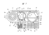
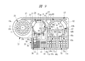
- it may be increased or decreased as appropriate. If the number is reduced, the apparatus can be further simplified, and if the number is increased, the processing efficiency can be further improved. A modification in which the number of such reagent dispensing mechanisms is changed will be described. 7 to 9 are schematic plan views showing an outline of a modification of the automatic analyzer of the present invention.
- the automatic analyzer 1b shown in FIG. 7 has two reagent dispensing mechanisms, ie, first and second reagent dispensing mechanisms 65a and 65b, which function as pretreatment liquid dispensing mechanisms.
- the intermediate disk 20 is also used for dispensing the pretreatment liquid and the flow system analysis reagent. That is, the reagent dispensing mechanism is commonly used in the inspection mechanism of a plurality of items.
- the reagent dispensing mechanism is only one of the first reagent dispensing mechanism 65a, and the reagent dispensing mechanism is further shared.
- the automatic analyzer 1d shown in FIG. 9 has only first and second reagent dispensing mechanisms 65a and 65b as reagent dispensing mechanisms for dispensing reagents to the reaction disk 60.
- third and fourth reagent dispensing mechanisms 65c and 65d are further provided.
- the third and fourth reagent dispensing mechanisms 65c and 65d are arranged in the same manner as the third and fourth reagent dispensing arms 66c and 66d.
- Horizontal rails 68c and 68d that slide in the direction are provided.
- a vertical rail 69 is provided between the horizontal rails 68a and 68b and the horizontal rails 68c and 68d, and the vertical rail 69 is shared by the first to fourth reagent dispensing mechanisms 65a to 65d.
- the biochemical test reagent cassette 70 is divided into two regions via a vertical rail 69.
- the biochemical examination reagent cassette 70 on the third and fourth reagent dispensing mechanisms 65c, 65d side has a third reagent holding part 71c for holding the third reagent and a fourth reagent holding the fourth reagent.
- the reagent holding part 71d is formed in the same manner as the first and second reagent holding parts 71a and 71b.
- the automatic analyzer 1d has four reagent dispensing mechanisms for dispensing reagents to the reaction disk 60, the first and second reagent dispensing mechanisms are used for items that are frequently requested, such as biochemical examinations.
- 65a and 65b and the 3rd and 4th reagent dispensing mechanism 65c and 65d can be divided into two and processed more quickly.
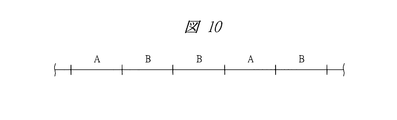
- FIG. 10 is an explanatory diagram for explaining the basic cycle
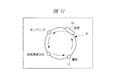
- FIG. 11 is an explanatory diagram for explaining the rotation operation of the intermediate disk in the A cycle
- FIGS. 12A and 12B are explanations for explaining the rotation operation of the intermediate disk in the B cycle.
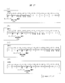
- FIG. FIGS. 13A to 13D are explanatory views for explaining the operation when the basic cycle of FIG. 10 is the shortest cycle
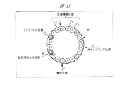
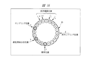
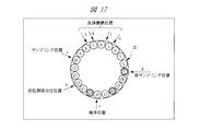
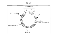
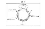
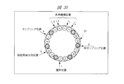
- FIGS. 14 to 20 are the rotation operations of the intermediate disk when 20 containers are arranged.
- FIG. 11, FIG. 12, and FIGS. 14 to 20 the arrangement of the intermediate disk is omitted or changed as appropriate for the convenience of understanding.
- the automatic analyzers 1a to 1d perform the A cycle in which the preprocessing operation is performed on the intermediate disk, and the resampling (sample redispensing) operation to the reaction disk and the flow system analysis mechanism (analysis unit).
- a basic cycle is formed by combining the B cycle to be performed. That is, the A cycle and the B cycle are independently controlled by the control unit, but the cycle time is made the same, thereby aligning the operation timing of the preprocessing and the operation timing to the analysis unit.
- the sample dispensing operation is performed from the sample disk to the reaction disk. To distinguish it from the sample dispensing operation to the intermediate disk, this is also referred to as “resampling”. Called.
- the A cycle corresponds to the dispensing operation of the flow system analysis reagent to the intermediate disk 20.
- the A cycle may be used for the B cycle operation.
- two B cycles are included after the A cycle.
- the number of B cycles after the A cycle is appropriately changed according to the inspection item, the number of samples, and the like. May be.
- sampling sample dispensing
- pretreatment liquid dispensing stirring, and washing are each performed in one cycle.
- the intermediate disk 20 is regularly rotated in one direction by a step that is a factor common to the number of arranged containers, such as x containers, for example, or one other than that.
- the B cycle operates at the stage where a series of operations up to the stirring in the A cycle is completed and a sample to be resampled is ready.
- the container to be resampled next moves to the resample position regardless of the position of the intermediate disk 20.
- the movement distance is arbitrary, but the intermediate disk 20 can select either the clockwise rotation shown in FIG. 12A or the counterclockwise rotation shown in FIG. It is possible to reduce the travel distance and time.
- the resampling operation is performed in the B cycle time of the optimum number of cycles according to the contents of the requested item. That is, the operation cycle time for re-sampling (the sample operation cycle time for dispensing a sample to a plurality of inspection mechanisms) is n times the minimum operation cycle time.
- the re-sampling operation cycle time corresponds to n times the rotation operation cycle time of the intermediate disk 20 in the inspection item via the intermediate disk 20.
- n may include an intermediate value between integers such as 1.5, but is preferably an integer in consideration of ease of control.
- the first sample (sample 1) is sampled.
- the pretreatment liquid is dispensed into the sample 1 and the sample 2 following the sample 1 is sampled.
- the sample 1 is agitated and the pretreatment liquid is dispensed to the sample 2 as shown in FIGS. Then, the sample 3 following the sample 2 is sampled. Sample 1 is resampled in two B cycles in the same basic cycle following the third A cycle. In the illustrated example, since there are six biochemical test items, the sample 1 is resampled in two B cycles in the next and the next basic cycle.
- the sample 2 is stirred and the pretreatment liquid is dispensed into the sample 3. Then, the sample 4 following the sample 3 is sampled.
- the sample 1 is resampled, and therefore the sample 2 is not resampled.
- the sample 3 is agitated and the pretreatment liquid is dispensed into the sample 4. And although illustration is abbreviate
- the sample 4 is stirred as shown in FIG. Then, sample dispensing and pretreatment liquid dispensing following sample 4 (not shown) are performed. Further, as shown in FIG. 13B, the sample 2 is resampled in two B cycles in the same basic cycle following the sixth A cycle. Note that, similarly to the sample 1, the sample 2 is resampled in the two B cycles in the next and the next basic cycle. Therefore, the sample 3 and the sample 4 are not resampled in the B cycle during this period.
- the sample 3 is resampled in the B cycle of the next three basic cycles after the re-sampling of the sample 2 is completed.
- sampling is performed at the position a in the container numbered 1 at the timing of the A cycle.
- the intermediate disk 20 rotates counterclockwise by three containers at the timing of the next A cycle, and the pretreatment liquid is dispensed at the position b in the container numbered 1. As it is poured, the container numbered 18 is sampled at position a.
- the intermediate disk 20 further rotates three containers counterclockwise at the timing of the next A cycle, and the container numbered 1 is at the position c.
- the pretreatment liquid is dispensed at the position b in a container numbered 18.
- Sampling is performed at the position c in the container numbered 15.
- the container numbered 1 moves to the position d by the rotation of the intermediate disk 20, and re-sampling is performed at this position.
- the container numbered 18 is moved to the position c by the rotation of the intermediate disk 20, and the sample is stirred at this position.
- the pretreatment liquid is dispensed into the containers numbered 15 at position b. Sampling is performed at the position a in the container numbered 12.
- the container numbered 18 is moved to the position d by the rotation of the intermediate disk 20 as shown in FIG. 20. Resampling is performed at this position. In this state, the samples numbered 15 and 12 are already stirred, the sample numbered 9 is dispensed with the pretreatment liquid, and the numbered sample 6 is already sampled.
- sample after completion of the re-sampling is sequentially subjected to sample suction, cleaning liquid discharge, cleaning, and cleaning liquid suction by a cleaning mechanism (not shown) at positions e to h at the timing of A cycle as necessary.
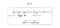
- the disk 20 operates as shown in FIG.
- sampling, pretreatment liquid dispensing, and stirring are sequentially performed as in the shortest cycle.
- the B cycle as shown in FIG. 21A, of the two B cycles in the same basic cycle as the A cycle in which the sample 1 is stirred, the first resampling is performed in the later B cycle. Is done. This prevents the next resampling from overlapping with the A cycle of the next basic cycle.
- next re-sampling of the sample 1 is performed in the first B cycle in the basic cycle next to the basic cycle in which the first re-sampling is performed. Further, since the next re-sampling overlaps with the A cycle, it is shifted to the first B cycle in the same basic cycle.
- the sample 2 is first resampled in the B cycle in the next basic cycle after the resample of the sample 1 is completed. Since the cycle interval of the sample 2 does not overlap with the A cycle, the re-sampling is sequentially performed in the first B cycle in the basic cycle.
- sampling, pretreatment liquid dispensing, and stirring are sequentially performed in the A cycle as in the case of the shortest cycle, as shown in FIG.
- resampling is not performed until a predetermined preprocessing time elapses. Re-sampling is performed at the timing of the B cycle after the preprocessing time has elapsed.
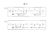
- FIGS. 24A to 24D are explanatory diagrams for explaining an example of the operation in the immune serum test
- FIG. (C) to (c) are explanatory views for explaining an example of the operation when a biochemical test and an immune serum test are combined.
- an empty cycle in which re-sampling is not performed is set in advance in the B cycle, and this empty cycle is used for cleaning the fixed container. Re-sampling is performed in the B cycle next to the empty cycle.
- the resampling operation cycle is longer than the biochemical test because of the analysis principle, so the operation cycle time is set to at least twice the minimum operation cycle time (n ⁇ 2).
- resampling timing does not overlap with the A cycle as shown in FIG.
- resampling is performed in the later B cycle in the basic cycle from the viewpoint of facilitating re-sampling timing control.
- resampling is performed in the first B cycle in the same cycle. May be.
- the re-sampling timing may overlap with the sampling operation of the next sample in the A cycle, as shown in FIG. In that case, as shown in FIG. 24 (c), in the corresponding A cycle, the sampling of the next sample is prioritized, and the resampling is shifted by one cycle, and the first B cycle in the same basic cycle as the A cycle. To do.
- the operation example in this immune serum test can be applied in the same manner to other flow system analysis test items such as a blood coagulation test.
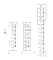
- FIGS. 27 (a) to (c) are explanatory diagrams for explaining an example of the operation according to priority determination
- FIG. It is explanatory drawing explaining the overlap of an injection mechanism.
- an emergency test item such as an item requested for an electrolyte test (ISE) or a rapid process
- Judgment is made on whether or not there are inspection items for which pre-processing time is set because it is necessary to leave or warm at a constant temperature. If these items exist, priority is given in the order of (i) and (ii). To process.
- how many times the operation cycle time for re-sampling each inspection item to the inspection mechanism is the minimum operation cycle time, that is, the number of cycle times n of each analysis unit. And the necessity of avoiding carryover of the reagent in the analysis unit. Then, a test item with a large number of n is preferentially processed, and if there is a need to avoid reagent carry-over, an empty cycle is set in advance.
- the reagent dispensing mechanism is shared between the intermediate disk and the reaction disk.
- the first reagent (5th item of biochemical examination after re-sampling) R1
- the timing of dispensing and the reagent dispensing in the item of immune serum test of n 2 overlap, and the latter timing may have to be shifted.
- the timing of the re-sampling of the immune serum test is shifted in advance by one cycle.
- the automatic analyzer 1a may perform the analysis by combining an inspection mechanism that can set the operation cycle time for re-sampling described above to an arbitrary time other than n times the minimum operation cycle time. Thereby, further quick processing of inspection of a plurality of items can be performed.
- the re-sampling operation cycle time for each inspection item is set to n times the minimum cycle time, so that a plurality of different analysis principles can be obtained without complicating the apparatus configuration. These inspections can be performed efficiently by aligning resampling timing in the inspection of items.
- the following (1) to (4) can be achieved by aligning the resampling timing in the inspection of multiple items so as to correspond to the minimum operation cycle time.
- resampling timings are not aligned among multiple items, inspection of items with short cycle times may not be in time between items with long cycle times, or time may be left even after the inspection is completed.
- aligning the timing of resampling it is possible to inspect items with short cycle time between inspection items with long cycle time without excess or shortage of time, and efficient processing of inspection of multiple items is possible. It can be planned. This also makes it possible to inspect items with a large number of requests between inspection items with a small number of requests.
- the re-sampling operation cycle time does not correspond to the minimum operation cycle time, it is difficult to perform resampling when there is no pre-processing operation or the like in the A cycle, but the re-sampling operation cycle time becomes the minimum operation cycle time. This is made possible by setting the number to n times, and an efficient process for inspecting a plurality of items can be achieved.
- the pretreatment liquid dispensing mechanism is shared for reagent dispensing, and when there is no reagent dispensing for the corresponding item, the pretreatment liquid for biochemical inspection is dispensed.
- a common reagent dispensing mechanism such as
- the timing of resampling is not aligned among multiple test items, a reagent dispensing mechanism is required for each test item mechanism in order to maintain processing capability, and the system configuration becomes complicated.
- the reagent dispensing mechanism can be shared and the apparatus configuration can be simplified without reducing the processing capacity. If the reagent dispensing mechanism can be shared, the disk for pretreatment can be shared for the reaction of inspection items with a long cycle time, and the apparatus configuration can be further simplified. Become.
- priority determination it is possible not only to respond quickly to emergency inspection items, but also to prioritize inspections for items for which pre-processing time is set or items with long cycle times, Due to the length, it is possible to prevent variations in the end of the inspection.
- uniformly setting the priority determination to avoid reagent carry-over and reagent dispensing mechanism overlap the occurrence of these situations can be avoided more reliably and processing can be made more efficient. I can plan. In other words, the control of each operation can be systematically performed by the priority determination, and the inspection of a plurality of items can be processed more efficiently.
- the present invention can be used in an automatic analyzer that automatically analyzes components such as blood.
Landscapes
- Chemical & Material Sciences (AREA)
- General Health & Medical Sciences (AREA)
- Life Sciences & Earth Sciences (AREA)
- Health & Medical Sciences (AREA)
- Analytical Chemistry (AREA)
- Biochemistry (AREA)
- Physics & Mathematics (AREA)
- General Physics & Mathematics (AREA)
- Immunology (AREA)
- Pathology (AREA)
- Chemical Kinetics & Catalysis (AREA)
- Automatic Analysis And Handling Materials Therefor (AREA)
- Investigating Or Analysing Biological Materials (AREA)
Abstract
Description
1試料当たり複数項目の検査のための分注を行うと、ディスクは再分注の間、一定の位置で停止してサンプリングを繰り返すので、その間に新規の試料の希釈や容器の洗浄ができず、装置の処理能力が低下する。
試料の前処理には、処理時間に制限がない項目と、一定にすることが必要な項目とがある。例えば、酵素、タンパク質等の検査項目では、単なる希釈のため、試料を一定倍率で希釈さえすればよい。これに対し、例えば、血液中の血球成分であるHbA1cの測定等では、赤血球成分試料を分取した後に一定量の希釈液を注入して溶血するために、一定時間放置あるいは一定温度で加温する必要がある。
各検査項目で分析原理が異なるので反応時間も異なる。例えば、生化学や血液凝固検査では、反応中に一定間隔で複数回測定するのに対し、免疫血清検査では、一定時間経過後の測定のみで、反応途中の測定はない。また、分析サイクルが異なるため、複数の検査を1台の装置で行うには制御が複雑となり、効率的な処理ができない。
1b 自動分析装置
1c 自動分析装置
1d 自動分析装置
10 試料ディスク
10a 外周
10b 中心
11 試料容器
15 試料分注機構
16 試料分注アーム
17 水平レール
18 鉛直レール
20 中間ディスク(ディスク)
21 ディスポーザブル容器(中間容器)
23 洗浄機構
30a フロー系分析機構(検査機構)
30b フロー系分析機構(検査機構)
30c フロー系分析機構(検査機構)
40 前処理液およびフロー系分析試薬容器収納部(前処理液容器等収納部)
41 容器
45 前処理液およびフロー系分析試薬分注機構(前処理液等分注機構)
46 前処理液等分注アーム
47 鉛直レール
48 水平レール
50 ディスポーザブル容器収納部
55 ディスポーザブル容器移送機構
56 容器把持アーム
57 鉛直レール
58 水平レール
60 反応ディスク(検査機構)
61 反応容器
62 測光機構
63 洗浄機構
65a 第1の試薬分注機構
65b 第2の試薬分注機構
65c 第3の試薬分注機構
65d 第4の試薬分注機構
66a 第1の試薬分注アーム
66b 第2の試薬分注アーム
66c 第3の試薬分注アーム
66d 第4の試薬分注アーム
67 鉛直レール
68a 水平レール
68b 水平レール
68c 水平レール
68d 水平レール
69 鉛直レール
70 生化学検査用試薬カセット
71a 第1の試薬保持部
71b 第2の試薬保持部
71c 第3の試薬保持部
71d 第4の試薬保持部
L1 試料の流れ
L2 試料の流れ
L3 前処理液等の流れ
L4 ディスポーザブル容器の流れ
L5 試薬の流れ
Claims (6)
- 試料容器内から分注された試料の前処理液による前処理または前記試料と試薬との反応を行う中間容器が配置されるディスクと、前記試料容器内または前記中間容器内から分注された前記試料の複数項目の検査機構とを有する自動分析装置であって、前記試料容器内または前記中間容器内から前記複数項目の検査機構への前記試料の分注動作サイクル時間が、各検査項目の最小動作サイクル時間のn倍(nは整数または整数間の中間値)であることを特徴とする自動分析装置。
- 請求項1に記載の自動分析装置において、前記最小動作サイクル時間は、前記ディスクを介する場合のその回転動作サイクル時間であることを特徴とする自動分析装置。
- 請求項1または2に記載の自動分析装置において、前記試料の分注動作サイクルに空きサイクルを設定したことを特徴とする自動分析装置。
- 請求項1~3のいずれか1項に記載の自動分析装置において、下記(a)、(b)の優先度判定を行うことを特徴とする自動分析装置:
(a)(i)緊急検査項目および/または(ii)前処理時間が定められた検査項目があった場合に、前記(i)、(ii)の順で優先して処理する優先度判定、
(b)nの数が大きい検査項目を優先して処理するとともに、前記検査機構における試薬分注時のキャリーオーバーを回避するために前記試料の分注動作サイクルに空きサイクルを設定する優先度判定。 - 請求項4に記載の自動分析装置において、さらに、(c)前記試薬を分注する試薬分注機構が、前記複数項目の検査機構で共通する場合に、同じ動作サイクルにおける前記試薬分注機構による前記試薬の分注タイミングの重なりを回避するために前記空きサイクルを設定する優先度判定を行うことを特徴とする自動分析装置。
- 請求項1~5のいずれか1項に記載の自動分析装置において、前記試料の分注動作サイクル時間を前記最小動作サイクル時間のn倍以外である任意の時間に設定できる前記検査機構を組み合わせたことを特徴とする自動分析装置。
Priority Applications (4)
| Application Number | Priority Date | Filing Date | Title |
|---|---|---|---|
| CN201080015157.1A CN102378916B (zh) | 2009-04-09 | 2010-04-08 | 自动分析装置 |
| JP2011508391A JP5531010B2 (ja) | 2009-04-09 | 2010-04-08 | 自動分析装置 |
| US13/262,671 US20120048036A1 (en) | 2009-04-09 | 2010-04-08 | Automatic analysis apparatus |
| EP10761744.1A EP2418494A4 (en) | 2009-04-09 | 2010-04-08 | Autoanalyzer |
Applications Claiming Priority (2)
| Application Number | Priority Date | Filing Date | Title |
|---|---|---|---|
| JP2009-094817 | 2009-04-09 | ||
| JP2009094817 | 2009-04-09 |
Publications (1)
| Publication Number | Publication Date |
|---|---|
| WO2010117045A1 true WO2010117045A1 (ja) | 2010-10-14 |
Family
ID=42936326
Family Applications (1)
| Application Number | Title | Priority Date | Filing Date |
|---|---|---|---|
| PCT/JP2010/056397 Ceased WO2010117045A1 (ja) | 2009-04-09 | 2010-04-08 | 自動分析装置 |
Country Status (5)
| Country | Link |
|---|---|
| US (1) | US20120048036A1 (ja) |
| EP (1) | EP2418494A4 (ja) |
| JP (1) | JP5531010B2 (ja) |
| CN (1) | CN102378916B (ja) |
| WO (1) | WO2010117045A1 (ja) |
Cited By (3)
| Publication number | Priority date | Publication date | Assignee | Title |
|---|---|---|---|---|
| WO2017138285A1 (ja) * | 2016-02-10 | 2017-08-17 | 株式会社 日立ハイテクノロジーズ | 自動分析装置 |
| JPWO2021070546A1 (ja) * | 2019-10-09 | 2021-04-15 | ||
| EP4592686A1 (en) | 2024-01-26 | 2025-07-30 | Jeol Ltd. | Automatic analyzer |
Families Citing this family (11)
| Publication number | Priority date | Publication date | Assignee | Title |
|---|---|---|---|---|
| EP2752247A3 (en) * | 2010-07-23 | 2016-08-31 | Beckman Coulter, Inc. | System or method of including analytical units |
| EP2860528B1 (en) | 2012-06-11 | 2018-01-03 | Hitachi High-Technologies Corporation | Automatic analysis apparatus |
| US9835612B2 (en) * | 2012-12-26 | 2017-12-05 | Hitachi High-Technologies Corporation | Automatic analyzer |
| EP3088901B1 (en) * | 2013-12-25 | 2025-07-02 | Hitachi High-Tech Corporation | Automatic analysis device and analysis method |
| EP3314269A4 (en) | 2015-06-26 | 2019-01-23 | Abbott Laboratories | REACTION TANK EXCHANGER DEVICE FOR DIAGNOSTIC ANALYZER |
| EP3460467A4 (en) * | 2016-05-20 | 2020-04-15 | Shimadzu Corporation | PRETREATMENT DEVICE AND ANALYSIS SYSTEM PROVIDED WITH SAME |
| MX2021012550A (es) * | 2019-04-26 | 2021-11-12 | Hitachi High Tech Corp | Analizador automatico. |
| CN113811773B (zh) * | 2019-05-13 | 2024-07-26 | 株式会社日立高新技术 | 自动分析装置及其清洗方法 |
| CN112904030B (zh) * | 2019-12-03 | 2025-05-27 | 深圳迈瑞生物医疗电子股份有限公司 | 一种供液系统及其方法 |
| CN111122846B (zh) * | 2019-12-13 | 2023-07-04 | 深圳加美生物有限公司 | 一种免疫层析检测的试剂卡孵化控制方法以及系统 |
| CN111735973B (zh) * | 2020-06-30 | 2022-05-27 | 深圳市科曼医疗设备有限公司 | 一种样本分析装置及其控制方法 |
Citations (9)
| Publication number | Priority date | Publication date | Assignee | Title |
|---|---|---|---|---|
| JPH0580059A (ja) * | 1991-09-20 | 1993-03-30 | Hitachi Ltd | 自動分析装置 |
| JPH0798321A (ja) * | 1993-09-29 | 1995-04-11 | Hitachi Ltd | 液体試料分析装置 |
| JPH08194004A (ja) | 1995-01-19 | 1996-07-30 | Jeol Ltd | 生化学自動分析装置 |
| JPH08313537A (ja) * | 1995-05-19 | 1996-11-29 | Hitachi Ltd | 自動分析装置 |
| JPH11211731A (ja) * | 1998-01-22 | 1999-08-06 | Olympus Optical Co Ltd | 自動分析装置 |
| JP2001013151A (ja) | 1999-06-30 | 2001-01-19 | Mitsubishi Chemicals Corp | 血液の検査装置 |
| JP2001027639A (ja) | 1999-07-15 | 2001-01-30 | Mitsubishi Chemicals Corp | 血液の検査方法 |
| WO2006107016A1 (ja) * | 2005-04-01 | 2006-10-12 | Mitsubishi Kagaku Iatron, Inc. | 生体サンプルの複合自動分析装置、自動分析方法、及び反応キュベット |
| WO2008050396A1 (en) * | 2006-10-24 | 2008-05-02 | Olympus Corporation | Analyzer |
Family Cites Families (7)
| Publication number | Priority date | Publication date | Assignee | Title |
|---|---|---|---|---|
| JP3063584B2 (ja) * | 1995-09-05 | 2000-07-12 | 株式会社日立製作所 | 自動分析装置 |
| ES2245462T3 (es) * | 1996-04-26 | 2006-01-01 | Dade Behring Inc. | Procedimiento y aparato para retratar muestras en un analizador quimico automatico. |
| JP4558995B2 (ja) * | 2001-09-12 | 2010-10-06 | ベックマン コールター, インコーポレイテッド | 移送ユニットおよびその移送ユニットを備える自動分析装置 |
| JP4349893B2 (ja) * | 2003-12-05 | 2009-10-21 | 株式会社日立ハイテクノロジーズ | 自動分析装置及び自動分析装置の分析方法 |
| JP4812352B2 (ja) * | 2005-07-21 | 2011-11-09 | 株式会社東芝 | 自動分析装置及びその分注方法 |
| US9459269B2 (en) * | 2005-07-22 | 2016-10-04 | Siemens Healthcare Diagnostics Inc. | Assay timing in a clinical analyzer using a cuvette carrier |
| JP5097522B2 (ja) * | 2007-12-07 | 2012-12-12 | 株式会社日立ハイテクノロジーズ | 自動分析装置 |
-
2010
- 2010-04-08 US US13/262,671 patent/US20120048036A1/en not_active Abandoned
- 2010-04-08 CN CN201080015157.1A patent/CN102378916B/zh active Active
- 2010-04-08 JP JP2011508391A patent/JP5531010B2/ja active Active
- 2010-04-08 EP EP10761744.1A patent/EP2418494A4/en not_active Withdrawn
- 2010-04-08 WO PCT/JP2010/056397 patent/WO2010117045A1/ja not_active Ceased
Patent Citations (9)
| Publication number | Priority date | Publication date | Assignee | Title |
|---|---|---|---|---|
| JPH0580059A (ja) * | 1991-09-20 | 1993-03-30 | Hitachi Ltd | 自動分析装置 |
| JPH0798321A (ja) * | 1993-09-29 | 1995-04-11 | Hitachi Ltd | 液体試料分析装置 |
| JPH08194004A (ja) | 1995-01-19 | 1996-07-30 | Jeol Ltd | 生化学自動分析装置 |
| JPH08313537A (ja) * | 1995-05-19 | 1996-11-29 | Hitachi Ltd | 自動分析装置 |
| JPH11211731A (ja) * | 1998-01-22 | 1999-08-06 | Olympus Optical Co Ltd | 自動分析装置 |
| JP2001013151A (ja) | 1999-06-30 | 2001-01-19 | Mitsubishi Chemicals Corp | 血液の検査装置 |
| JP2001027639A (ja) | 1999-07-15 | 2001-01-30 | Mitsubishi Chemicals Corp | 血液の検査方法 |
| WO2006107016A1 (ja) * | 2005-04-01 | 2006-10-12 | Mitsubishi Kagaku Iatron, Inc. | 生体サンプルの複合自動分析装置、自動分析方法、及び反応キュベット |
| WO2008050396A1 (en) * | 2006-10-24 | 2008-05-02 | Olympus Corporation | Analyzer |
Non-Patent Citations (1)
| Title |
|---|
| See also references of EP2418494A4 * |
Cited By (7)
| Publication number | Priority date | Publication date | Assignee | Title |
|---|---|---|---|---|
| WO2017138285A1 (ja) * | 2016-02-10 | 2017-08-17 | 株式会社 日立ハイテクノロジーズ | 自動分析装置 |
| JPWO2017138285A1 (ja) * | 2016-02-10 | 2018-12-20 | 株式会社日立ハイテクノロジーズ | 自動分析装置 |
| US11073526B2 (en) | 2016-02-10 | 2021-07-27 | Hitachi High-Tech Corporation | Automatic analysis device |
| JPWO2021070546A1 (ja) * | 2019-10-09 | 2021-04-15 | ||
| WO2021070546A1 (ja) * | 2019-10-09 | 2021-04-15 | 株式会社日立ハイテク | 自動分析装置 |
| JP7210760B2 (ja) | 2019-10-09 | 2023-01-23 | 株式会社日立ハイテク | 自動分析装置 |
| EP4592686A1 (en) | 2024-01-26 | 2025-07-30 | Jeol Ltd. | Automatic analyzer |
Also Published As
| Publication number | Publication date |
|---|---|
| EP2418494A1 (en) | 2012-02-15 |
| JPWO2010117045A1 (ja) | 2012-10-18 |
| JP5531010B2 (ja) | 2014-06-25 |
| CN102378916A (zh) | 2012-03-14 |
| CN102378916B (zh) | 2015-02-18 |
| US20120048036A1 (en) | 2012-03-01 |
| EP2418494A4 (en) | 2018-01-10 |
Similar Documents
| Publication | Publication Date | Title |
|---|---|---|
| JP5531010B2 (ja) | 自動分析装置 | |
| JP5564037B2 (ja) | 自動分析装置 | |
| CN104024867B (zh) | 自动分析装置和试样分注探针清洗方法 | |
| JP6742463B2 (ja) | 自動分析装置およびメンテナンスの要否を推奨する方法 | |
| JP5097522B2 (ja) | 自動分析装置 | |
| JP3609945B2 (ja) | 自動分析方法及び装置 | |
| JP5732521B2 (ja) | 自動分析装置 | |
| US20120039748A1 (en) | Automatic analysis apparatus | |
| JP6634222B2 (ja) | 体外診断分析方法およびシステム | |
| JP2013536951A (ja) | 全血混合の完全さを決定するための全血吸引の圧力モニタリング | |
| JP2011163909A (ja) | 自動分析装置および分注手段の洗浄方法 | |
| JP5337600B2 (ja) | 自動分析装置及び自動分析装置の制御方法 | |
| JP3391734B2 (ja) | 生体サンプルの取扱い方法及び分析装置 | |
| JP4101466B2 (ja) | 生体サンプルの分析装置 | |
| JP4153171B2 (ja) | 生体サンプルの分析方法 | |
| JP5337727B2 (ja) | 自動分析装置 | |
| JP3380542B2 (ja) | 生体サンプルの分析方法 | |
| JPH0526882A (ja) | 多項目同時処理自動分析装置及びその分析処理方法 | |
| JP6234765B2 (ja) | 検体検査自動分析システム | |
| JP4537472B2 (ja) | 分析装置 | |
| JP2016148571A (ja) | 自動分析装置及び自動分析方法 | |
| JP2019090639A (ja) | 自動分析装置 | |
| JPH03272467A (ja) | 自動化学分析装置 | |
| CN115715370A (zh) | 自动分析装置 | |
| JP2001264343A (ja) | 生体サンプルの分析装置 |
Legal Events
| Date | Code | Title | Description |
|---|---|---|---|
| WWE | Wipo information: entry into national phase |
Ref document number: 201080015157.1 Country of ref document: CN |
|
| 121 | Ep: the epo has been informed by wipo that ep was designated in this application |
Ref document number: 10761744 Country of ref document: EP Kind code of ref document: A1 |
|
| WWE | Wipo information: entry into national phase |
Ref document number: 2011508391 Country of ref document: JP |
|
| WWE | Wipo information: entry into national phase |
Ref document number: 13262671 Country of ref document: US |
|
| WWE | Wipo information: entry into national phase |
Ref document number: 2010761744 Country of ref document: EP |
|
| NENP | Non-entry into the national phase |
Ref country code: DE |