WO2010114080A1 - 機械式駐輪設備 - Google Patents
機械式駐輪設備 Download PDFInfo
- Publication number
- WO2010114080A1 WO2010114080A1 PCT/JP2010/055980 JP2010055980W WO2010114080A1 WO 2010114080 A1 WO2010114080 A1 WO 2010114080A1 JP 2010055980 W JP2010055980 W JP 2010055980W WO 2010114080 A1 WO2010114080 A1 WO 2010114080A1
- Authority
- WO
- WIPO (PCT)
- Prior art keywords
- bicycle
- bicycle parking
- hangar
- loading
- parking
- Prior art date
- Legal status (The legal status is an assumption and is not a legal conclusion. Google has not performed a legal analysis and makes no representation as to the accuracy of the status listed.)
- Ceased
Links
Images


Classifications
-
- E—FIXED CONSTRUCTIONS
- E04—BUILDING
- E04H—BUILDINGS OR LIKE STRUCTURES FOR PARTICULAR PURPOSES; SWIMMING OR SPLASH BATHS OR POOLS; MASTS; FENCING; TENTS OR CANOPIES, IN GENERAL
- E04H6/00—Buildings for parking cars, rolling-stock, aircraft, vessels or like vehicles, e.g. garages
- E04H6/005—Garages for vehicles on two wheels
-
- B—PERFORMING OPERATIONS; TRANSPORTING
- B62—LAND VEHICLES FOR TRAVELLING OTHERWISE THAN ON RAILS
- B62H—CYCLE STANDS; SUPPORTS OR HOLDERS FOR PARKING OR STORING CYCLES; APPLIANCES PREVENTING OR INDICATING UNAUTHORIZED USE OR THEFT OF CYCLES; LOCKS INTEGRAL WITH CYCLES; DEVICES FOR LEARNING TO RIDE CYCLES
- B62H3/00—Separate supports or holders for parking or storing cycles
- B62H2003/005—Supports or holders associated with means for bike rental
Definitions
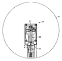
- FIG. 6 is a vertical sectional view showing a conventional mechanical bicycle parking facility
- FIG. 7 is a sectional view taken along the line AA in FIG. 6
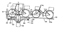
- FIG. 8 is a sectional view taken along the line BB in FIG. It is a side view which shows a bicycle parking machine mechanism.
- the conventional mechanical bicycle parking facility includes a cylindrical hangar 21 made of a cylindrical concrete frame constructed underground, and a bicycle provided on the ground portion of the hangar 21.
- the hangar 21 may be constructed underground as in this example or constructed on the ground.
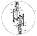
- the bicycle parking mechanism 24 includes a gate-shaped guide rail 25 provided perpendicularly to the center of the hangar 21, a lifting body 26 that can be lifted and lowered along the guide rail 25, and a lifting body. 26 and a transfer device 27 provided in 26.
- the guide rail 25 can be rotated around the axis of the hangar 21 by a driving machine 28 (see FIG. 6).
- the elevating body 26 has a guide plate 29 having a V-shaped cross section on which a bicycle can be placed.
- the transfer device 27 has a function of pulling the bicycle from the loading / unloading port 22 and the storage unit 23 and pushing out the bicycle to the loading / unloading port 22 and the storage unit 23.
- the transfer device 27 has a pair of clamp plates 30 that clamp the front wheels of the bicycle.
- the clamp plate 30 sandwiches the front axle from both sides of the bicycle by a clamp plate drive 31.
- the clamp plate driver 31 is connected to an endless belt 33 that is stretched between a pair of pulleys 32.
- the endless belt 33 circulates between the pulleys 32.
- the clamp plate driver 31 moves in the horizontal direction along the guide plate 29, and the bicycle sandwiched between the clamp plates 30 also moves.
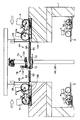
- a guide plate 34 having a V-shaped cross section similar to the guide plate 29 is disposed on the extension line of the guide plate 29 of the elevating body 26 at the bicycle delivery place outside the entrance / exit 22.
- the guide plate 34 is slightly lower than the ground.
- the user sets the bicycle on the guide plate 34 that is one step down from the ground.
- the guide plate 34 is slightly tilted so that the rear wheel side of the bicycle faces down.
- a portion of the guide plate 34 corresponding to the rear wheel of the bicycle is provided with a counter plate 35 for positioning the rear wheel.
- the entrance / exit 22 is provided between the guide plate 29 of the elevating body 26 and the guide plate 34 at the bicycle delivery position.
- the transfer device 27 holds the front wheel of the bicycle and pulls the bicycle from the bicycle delivery position onto the lift body 26 at the time of warehousing, the bicycle transfers from the guide plate 34 at the bicycle delivery position to the guide plate 29 of the lift body 6.
- the bicycle is transferred from the guide plate 29 of the lifting body 26 to the guide plate 34 at the bicycle delivery position, contrary to the time of entry.
- the bicycle is set on the guide plate 34 of the entrance / exit 22 and the entry button is pushed.
- the warehousing button When the warehousing button is pressed, the IC reader automatically and instantly reads the IC tag previously attached to the bicycle, and the warehousing operation is started. That is, the loading / unloading port 22 is opened, and thereafter, the transfer device 27 moves forward to clamp the front wheel of the bicycle.
- the bicycle is drawn onto the guide plate 29 of the lifting body 26 by the transfer device 27.
- the entrance / exit 22 is closed.
- the bicycle descends while rotating to the position of the predetermined storage portion 23 along the guide rail 25 together with the lifting body 26. After descending, the bicycle is automatically stored in the predetermined storage unit 23 from the rear wheel side by the transfer device 27.
- the hangar 21 Since the hangar 21 is equipped with only one lifting body 26, only one bicycle could be loaded and unloaded at a time. Therefore, it takes a long time for loading and unloading when a loading / unloading instruction is continuously given during loading and unloading peaks such as during morning and evening rush hours.
- an object of the present invention is to provide a mechanical bicycle parking facility capable of loading and unloading a plurality of bicycles at a time and efficiently loading and unloading bicycles even at the peak of loading and unloading.
- the present invention has been made to achieve the above object, and is characterized by the following.
- the two parking machine mechanisms are provided, and the one parking machine mechanism and the other parking machine mechanism are point-symmetric about the axis of the hangar.
- the transfer device of the one bicycle parking machine mechanism and the other bicycle parking machine mechanism are arranged so that the transfer directions of the bicycles are parallel to each other with a gap therebetween, and the transfer device
- the front wheels of the bicycle transferred to the lifting body are arranged so as to face each other.
- the guide rails of one parking machine mechanism and the other parking machine mechanism are common, and the guide rail is Provided along the axis of the hangar, and the one bicycle parking mechanism and the other bicycle parking mechanism are arranged in a row so that the transfer direction of the bicycle by the transfer device is along the radial direction of the hangar. And the front wheels of the bicycle transferred to the lifting body by the transfer device are arranged so as to face each other.
- FIG. 1 is a vertical sectional view showing a mechanical bicycle parking facility of the present invention.
- 2 is a cross-sectional view taken along line AA in FIG.
- FIG. 3 is a view taken along the line BB in FIG. 4 is a view in the direction of arrow C in FIG.
- FIG. 5 is a horizontal sectional view showing another mechanical bicycle parking facility of the present invention.
- FIG. 6 is a vertical sectional view showing a conventional mechanical bicycle parking facility.
- 7 is a cross-sectional view taken along line AA in FIG.
- FIG. 8 is a view taken along line B-B in FIG.
- FIG. 9 is a side view showing the bicycle parking mechanism.
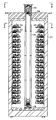
- reference numeral 1 denotes a cylindrical hangar made of a cylindrical concrete frame constructed underground, and 2 ⁇ / b> A and 2 ⁇ / b> B are entry / exit ports for taking in and out a bicycle provided on the ground portion of the hangar 1. is there.
- the entry / exit ports 2A and 2B are provided to face each other and correspond to each of two bicycle parking machine mechanisms described later.
- Reference numeral 3 denotes a plurality of storage units provided in a vertical and multistage manner in the hangar 1, and 4A and 4B are two bicycles for transporting a bicycle between the entrance / exit 2 and a predetermined storage unit 3. It is a mechanical mechanism.
- the hangar 1 is constructed underground in this example, but may be constructed on the ground.
- one parking machine mechanism 4A and the other parking machine mechanism 4B are arranged symmetrically with respect to the axis of the hangar 1, and one parking machine mechanism 4A and the other Bicycle transfer directions by the transfer device described later of the bicycle parking mechanism 4B are arranged so that the transfer directions of the bicycle are parallel with a certain interval, and the front wheels of the bicycle transferred to the lifting body described later by the transfer device are mutually connected. It is arranged to face each other.
- one bicycle parking mechanism 4A includes a guide rail 5A, an elevating body 6A that can be moved up and down along the guide rail 5A, and a transfer device 7A provided on the elevating body 6A.
- the other parking machine mechanism 4B includes a lifting body 6B that can be lifted and lowered along the guide rail 5B, and a transfer device 7B provided on the lifting body 6B, similarly to the one parking machine mechanism 4A.
- the guide rails 5A and 5B are vertically provided at equal intervals on both sides of the axis of the hangar 1, and are integrally formed around the axis of the hangar 1 by the drive unit 8 (see FIG. 1) together with the lifting bodies 6A and 6B. It can be rotated.
- the elevating body 6A has a guide plate 9A having a V-shaped cross section on which a bicycle can be placed.
- the transfer device 7 ⁇ / b> A has a function of pulling the bicycle from the loading / unloading port 2 ⁇ / b> A and the storage unit 3 and pushing out the bicycle to the loading / unloading port 2 ⁇ / b> A and the storage unit 3.
- the lifting body 6B has a guide plate 9B having a V-shaped cross section on which the bicycle can be placed.
- the transfer device 7B pulls the bicycle from the loading / unloading port 2B and the storage unit 3 and It has a function of pushing out to the exit 2B and the storage unit 3.
- the elevating body 6A and the elevating body 6B can be moved up and down independently along the guide rails 5A and 5B.
- the transfer device 7A has a pair of clamp plates 10A for clamping the front wheel of the bicycle.
- the clamp plate 10A sandwiches the axle of the front wheel from both sides of the bicycle by the clamp plate driver 11A.
- the transfer device 7B has a pair of clamp plates 10B that sandwich the axles of the front wheels from both sides of the bicycle by the clamp plate driver 11B.
- the clamp plate driver 11A is configured in the same manner as in the conventional mechanical bicycle parking facility described above. That is, the clamp plate driver 11A is connected to an endless belt 13 that is stretched between a pair of pulleys 12, as shown in FIG. When the pulley 12 is rotationally driven by a driving machine (not shown), the endless belt 13 circulates between the pulleys 12. As the endless belt 13 circulates, the clamp plate driver 11A moves in the horizontal direction along the guide plate 9A, and the bicycle sandwiched between the clamp plates 10A also moves.
- the clamp plate driver 11B is the same as the clamp plate driver 11A.
- a guide plate 14A having a V-shaped cross section similar to the guide plate 9A is disposed on the extension line of the guide plate 9A of the lifting body 6A at the bicycle delivery place outside the entrance / exit 2A. Yes.
- a guide plate 14B having a V-shaped cross section similar to that of the guide plate 9A is also arranged on the extension line of the lifting body 6B guide plate 9B at the bicycle delivery place outside the entrance / exit 2B.
- the guide plates 14A and 14B are slightly lower than the ground.
- the entrance / exit 2A, 2B is provided between the guide plates 9A, 9B of the elevating bodies 6A, 6B and the guide plate 14 at the bicycle delivery position.
- the transfer device 7A, 7B holds the front wheel of the bicycle and pulls the bicycle from the bicycle delivery position onto the lifting body 6A, 6B at the time of warehousing
- the bicycle moves from the guide plate 14A, 14B at the bicycle delivery position to the lifting body 6A, Transfer to 6B guide plates 9A, 9B.
- the bicycle is transferred from the guide plates 9A and 9B of the lifting bodies 6A and 6B to the guide plates 14A and 14B at the bicycle delivery position, contrary to the time of entry.
- bicycles are loaded and unloaded in the following manner.
- the entrance / exit 2A is closed. Thereafter, the bicycle descends while rotating to the position of the predetermined storage unit 3 along the guide rail 5A together with the elevating body 6A. After descending, the bicycle is automatically stored in the predetermined storage unit 3 from the rear wheel side by the transfer device 7A.
- the following is performed.
- the user sets the bicycle A on the guide plate 14A of the entrance / exit 2A and presses the entry button.
- the warehousing button is pressed, the IC reader automatically and instantly reads the IC tag previously attached to the bicycle A, and the warehousing operation is started. That is, the loading / unloading port 2A is opened, and thereafter, the transfer device 7A moves forward and clamps the front wheel of the bicycle A.
- the bicycle A is drawn onto the guide plate 9A of the elevating body 6A by the transfer device 7A.
- the transfer device is the same as in the case of the bicycle A from the entrance / exit 2A.
- the bicycle B is drawn onto the guide plate 9B of the lifting body 6B by 7B.
- the elevating body 6A and the elevating body 6B rotate individually together with the guide rails 5A, 5B to individually reach the predetermined height of the storage unit 3 respectively. Descends along the guide rails 5A and 5B. At this time, positioning in the turning direction is performed with priority given to one of the lifting bodies.
- priority is given to the lifting body A
- the bicycle A of the prioritized lifting body A is stored in the predetermined storage unit 3 by the transfer device 7A, and then the lifting body is again directed toward the predetermined storage unit 3 of the bicycle B.
- a priority method of the lifting body there is a method of giving priority to a lifting body with a small descending distance in the height direction, a method of giving priority to a lifting body with a small turning angle, or a method of giving priority to a lifting body that has received a warehousing instruction first.
- other methods can be set.
- the positioning in the turning direction can be performed once, so that the storage can be performed in a shorter time.
- the bicycle A And bicycle B can be simultaneously stored in the respective predetermined storage units 3.
- the unloading operation is performed by the reverse operation of the above-described loading operation, and the bicycles A and B stored in the storage unit 3 are discharged to the loading / unloading ports 2A and 2B, respectively.
- the exit command is applied to the bicycle A and the exit command is applied to the bicycle B before the pull-in of the bicycle A to the lift 6A is completed, the pull-out of the bicycle B to the lift 6B is completed.
- the lifts 6A and 6B of the platform enter into the unloading operation at the same time, and the bicycles A and B are pushed out onto the guide rails 14A and 14B of the respective loading / unloading ports 2A and 2B.
- the two lifting bodies 6A and 6B can be operated at the same time so that the bicycle can be efficiently stored and taken out.
- the above is a case where the two parking machine mechanisms 4A, 4B are arranged in parallel with the lifting bodies 6A, 6B.
- one parking machine mechanism 4A and the other parking machine mechanism 4A, 6B are arranged.
- the guide rail 5 of the wheel machine mechanism 4B is shared, the guide rail 5 is provided along the axis of the hangar 1, and one parking machine mechanism 4A and the other parking machine mechanism 4B are transferred by the transfer devices 7A and 7B.
- the transfer direction of the bicycle is along the radial direction of the hangar 1 and the front wheels of the bicycle transferred to the lifting bodies 6A, 6B by the transfer devices 7A, 7B are opposed to each other. Also good.
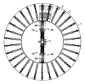
- the storage unit 3 is arranged radially around the axis of the hangar 1.
- the number of storage units per hangar can be increased without reducing the storage / processing time of bicycles.
- the hangar also has the effect of being able to construct a high-capacity mechanical bicycle parking facility.
- the operation has been described with the lifting body 6A corresponding to the loading / unloading port 2A and the lifting body 6B corresponding to the loading / unloading port 2B.
- the lifting body 6A corresponds to the loading / unloading port 2B and the lifting body 6B corresponds to the loading / unloading port 2A. There is no problem.
Landscapes
- Engineering & Computer Science (AREA)
- Architecture (AREA)
- Mechanical Engineering (AREA)
- Civil Engineering (AREA)
- Structural Engineering (AREA)
- Warehouses Or Storage Devices (AREA)
Applications Claiming Priority (2)
| Application Number | Priority Date | Filing Date | Title |
|---|---|---|---|
| JP2009-086081 | 2009-03-31 | ||
| JP2009086081 | 2009-03-31 |
Publications (1)
| Publication Number | Publication Date |
|---|---|
| WO2010114080A1 true WO2010114080A1 (ja) | 2010-10-07 |
Family
ID=42828369
Family Applications (1)
| Application Number | Title | Priority Date | Filing Date |
|---|---|---|---|
| PCT/JP2010/055980 Ceased WO2010114080A1 (ja) | 2009-03-31 | 2010-03-25 | 機械式駐輪設備 |
Country Status (2)
| Country | Link |
|---|---|
| JP (1) | JP2010255400A (enExample) |
| WO (1) | WO2010114080A1 (enExample) |
Cited By (6)
| Publication number | Priority date | Publication date | Assignee | Title |
|---|---|---|---|---|
| JP2012184611A (ja) * | 2011-03-07 | 2012-09-27 | Jfe Engineering Corp | 機械式自転車駐輪設備及び方法 |
| WO2014017919A1 (en) | 2012-07-27 | 2014-01-30 | W.A. Benecke Beheer B.V. | Storage for storing bicycles |
| CN106828672A (zh) * | 2017-03-29 | 2017-06-13 | 浙江工业大学 | 一种可锁多辆公共自行车的还车装置及其还车方法 |
| CN106915393A (zh) * | 2017-03-11 | 2017-07-04 | 梁崇彦 | 一种圆柱形共享自行车集中托管装置 |
| CN109441158A (zh) * | 2018-09-21 | 2019-03-08 | 武汉科技大学 | 一种蘑菇形自行车停放装置 |
| US11111688B2 (en) * | 2018-04-08 | 2021-09-07 | Beijing University Of Civil Engineering And Architecture | Three-dimensional rotating intelligent storage compartment |
Families Citing this family (3)
| Publication number | Priority date | Publication date | Assignee | Title |
|---|---|---|---|---|
| CN111140047A (zh) * | 2018-11-06 | 2020-05-12 | 天津职业技术师范大学 | 竖直放置式单车智能存放系统 |
| CN111021796A (zh) * | 2019-10-24 | 2020-04-17 | 杭州电子科技大学 | 一种旋转式多层自行车立体停车装置 |
| CN112523565A (zh) * | 2020-11-27 | 2021-03-19 | 丁宏毅 | 自行车立体车库用升降装置 |
Citations (4)
| Publication number | Priority date | Publication date | Assignee | Title |
|---|---|---|---|---|
| JPS62194367A (ja) * | 1986-02-18 | 1987-08-26 | 株式会社 白石 | 入出庫口用昇降式複数階自転車載置台を有する自転車立体駐車装置 |
| JP2000226107A (ja) * | 1999-02-03 | 2000-08-15 | Daifuku Co Ltd | 物品保管設備 |
| JP2006152715A (ja) * | 2004-11-30 | 2006-06-15 | Sumitomo Heavy Ind Ltd | 機械式駐輪場 |
| JP2008062750A (ja) * | 2006-09-06 | 2008-03-21 | Jfe Kankyo Solutions Kk | 機械式自転車駐輪設備 |
Family Cites Families (2)
| Publication number | Priority date | Publication date | Assignee | Title |
|---|---|---|---|---|
| JPS62189262A (ja) * | 1986-01-21 | 1987-08-19 | 株式会社 白石 | 自転車立体駐車装置 |
| JP3839914B2 (ja) * | 1997-07-03 | 2006-11-01 | 株式会社間組 | 立体駐輪装置 |
-
2010
- 2010-03-17 JP JP2010060978A patent/JP2010255400A/ja active Pending
- 2010-03-25 WO PCT/JP2010/055980 patent/WO2010114080A1/ja not_active Ceased
Patent Citations (4)
| Publication number | Priority date | Publication date | Assignee | Title |
|---|---|---|---|---|
| JPS62194367A (ja) * | 1986-02-18 | 1987-08-26 | 株式会社 白石 | 入出庫口用昇降式複数階自転車載置台を有する自転車立体駐車装置 |
| JP2000226107A (ja) * | 1999-02-03 | 2000-08-15 | Daifuku Co Ltd | 物品保管設備 |
| JP2006152715A (ja) * | 2004-11-30 | 2006-06-15 | Sumitomo Heavy Ind Ltd | 機械式駐輪場 |
| JP2008062750A (ja) * | 2006-09-06 | 2008-03-21 | Jfe Kankyo Solutions Kk | 機械式自転車駐輪設備 |
Cited By (9)
| Publication number | Priority date | Publication date | Assignee | Title |
|---|---|---|---|---|
| JP2012184611A (ja) * | 2011-03-07 | 2012-09-27 | Jfe Engineering Corp | 機械式自転車駐輪設備及び方法 |
| WO2014017919A1 (en) | 2012-07-27 | 2014-01-30 | W.A. Benecke Beheer B.V. | Storage for storing bicycles |
| CN104661905A (zh) * | 2012-07-27 | 2015-05-27 | W.A.贝奈克管理公司 | 用于存放自行车的仓库 |
| CN106915393A (zh) * | 2017-03-11 | 2017-07-04 | 梁崇彦 | 一种圆柱形共享自行车集中托管装置 |
| CN106915393B (zh) * | 2017-03-11 | 2019-03-12 | 梁崇彦 | 一种圆柱形共享自行车集中托管装置 |
| CN106828672A (zh) * | 2017-03-29 | 2017-06-13 | 浙江工业大学 | 一种可锁多辆公共自行车的还车装置及其还车方法 |
| CN106828672B (zh) * | 2017-03-29 | 2022-03-18 | 浙江工业大学 | 一种可锁多辆公共自行车的还车装置及其还车方法 |
| US11111688B2 (en) * | 2018-04-08 | 2021-09-07 | Beijing University Of Civil Engineering And Architecture | Three-dimensional rotating intelligent storage compartment |
| CN109441158A (zh) * | 2018-09-21 | 2019-03-08 | 武汉科技大学 | 一种蘑菇形自行车停放装置 |
Also Published As
| Publication number | Publication date |
|---|---|
| JP2010255400A (ja) | 2010-11-11 |
Similar Documents
| Publication | Publication Date | Title |
|---|---|---|
| WO2010114080A1 (ja) | 機械式駐輪設備 | |
| KR950002252B1 (ko) | 입체 주차장치 | |
| CN110482098B (zh) | 一种基于搬运机器人、系统的取放货方法 | |
| KR100453147B1 (ko) | 이동식 발을 이용한 주차차량 자동 이송장치 및 방법 | |
| KR101382195B1 (ko) | 자재 보관장치 | |
| US10794077B1 (en) | Mechanical parking garage | |
| JP2006152537A (ja) | 自転車駐輪設備 | |
| JP2006152715A (ja) | 機械式駐輪場 | |
| JPH09158513A (ja) | 機械式駐車装置 | |
| JP6006100B2 (ja) | 機械式駐車装置 | |
| JP5474619B2 (ja) | バリアフリー対応多段式駐車装置 | |
| JP2605144B2 (ja) | 水平循環式駐車装置 | |
| JP4361471B2 (ja) | 機械式駐車設備及び機械式駐車設備への入出庫方法、並びにコンピュータプログラム | |
| JP6664265B2 (ja) | 機械式駐車装置とその制御方法 | |
| JPH0224459A (ja) | 自動格納装置及び方法 | |
| CN114538328B (zh) | 堆垛机及立体仓库 | |
| JPH0768792B2 (ja) | 連棟形立体駐車装置 | |
| JPH09256661A (ja) | 機械式立体駐車装置 | |
| KR20110114814A (ko) | 환적형 자전거 주차 설비 | |
| JPH038627A (ja) | 段積み段ばらし装置 | |
| JPS62284864A (ja) | エレベータ式の立体駐車装置 | |
| JPH07259371A (ja) | 立体駐車装置 | |
| CN101191387B (zh) | 游艇的存取装置 | |
| JP2923716B2 (ja) | 循環移動式駐車装置 | |
| JPH10196148A (ja) | 立体駐車場 |
Legal Events
| Date | Code | Title | Description |
|---|---|---|---|
| 121 | Ep: the epo has been informed by wipo that ep was designated in this application |
Ref document number: 10758851 Country of ref document: EP Kind code of ref document: A1 |
|
| NENP | Non-entry into the national phase |
Ref country code: DE |
|
| 122 | Ep: pct application non-entry in european phase |
Ref document number: 10758851 Country of ref document: EP Kind code of ref document: A1 |