WO2010110090A1 - 光学フィルム、偏光板、および液晶表示装置 - Google Patents
光学フィルム、偏光板、および液晶表示装置 Download PDFInfo
- Publication number
- WO2010110090A1 WO2010110090A1 PCT/JP2010/054206 JP2010054206W WO2010110090A1 WO 2010110090 A1 WO2010110090 A1 WO 2010110090A1 JP 2010054206 W JP2010054206 W JP 2010054206W WO 2010110090 A1 WO2010110090 A1 WO 2010110090A1
- Authority
- WO
- WIPO (PCT)
- Prior art keywords
- liquid crystal
- film
- group
- optical film
- crystal layer
- Prior art date
- Legal status (The legal status is an assumption and is not a legal conclusion. Google has not performed a legal analysis and makes no representation as to the accuracy of the status listed.)
- Ceased
Links
Images


Classifications
-
- B—PERFORMING OPERATIONS; TRANSPORTING
- B32—LAYERED PRODUCTS
- B32B—LAYERED PRODUCTS, i.e. PRODUCTS BUILT-UP OF STRATA OF FLAT OR NON-FLAT, e.g. CELLULAR OR HONEYCOMB, FORM
- B32B27/00—Layered products comprising a layer of synthetic resin
- B32B27/18—Layered products comprising a layer of synthetic resin characterised by the use of special additives
- B32B27/22—Layered products comprising a layer of synthetic resin characterised by the use of special additives using plasticisers
-
- B—PERFORMING OPERATIONS; TRANSPORTING
- B32—LAYERED PRODUCTS
- B32B—LAYERED PRODUCTS, i.e. PRODUCTS BUILT-UP OF STRATA OF FLAT OR NON-FLAT, e.g. CELLULAR OR HONEYCOMB, FORM
- B32B27/00—Layered products comprising a layer of synthetic resin
- B32B27/06—Layered products comprising a layer of synthetic resin as the main or only constituent of a layer, which is next to another layer of the same or of a different material
-
- B—PERFORMING OPERATIONS; TRANSPORTING
- B32—LAYERED PRODUCTS
- B32B—LAYERED PRODUCTS, i.e. PRODUCTS BUILT-UP OF STRATA OF FLAT OR NON-FLAT, e.g. CELLULAR OR HONEYCOMB, FORM
- B32B27/00—Layered products comprising a layer of synthetic resin
- B32B27/18—Layered products comprising a layer of synthetic resin characterised by the use of special additives
-
- B—PERFORMING OPERATIONS; TRANSPORTING
- B32—LAYERED PRODUCTS
- B32B—LAYERED PRODUCTS, i.e. PRODUCTS BUILT-UP OF STRATA OF FLAT OR NON-FLAT, e.g. CELLULAR OR HONEYCOMB, FORM
- B32B27/00—Layered products comprising a layer of synthetic resin
- B32B27/30—Layered products comprising a layer of synthetic resin comprising vinyl (co)polymers; comprising acrylic (co)polymers
-
- B—PERFORMING OPERATIONS; TRANSPORTING
- B32—LAYERED PRODUCTS
- B32B—LAYERED PRODUCTS, i.e. PRODUCTS BUILT-UP OF STRATA OF FLAT OR NON-FLAT, e.g. CELLULAR OR HONEYCOMB, FORM
- B32B27/00—Layered products comprising a layer of synthetic resin
- B32B27/30—Layered products comprising a layer of synthetic resin comprising vinyl (co)polymers; comprising acrylic (co)polymers
- B32B27/308—Layered products comprising a layer of synthetic resin comprising vinyl (co)polymers; comprising acrylic (co)polymers comprising acrylic (co)polymers
-
- G—PHYSICS
- G02—OPTICS
- G02B—OPTICAL ELEMENTS, SYSTEMS OR APPARATUS
- G02B5/00—Optical elements other than lenses
- G02B5/30—Polarising elements
- G02B5/3016—Polarising elements involving passive liquid crystal elements
-
- B—PERFORMING OPERATIONS; TRANSPORTING
- B32—LAYERED PRODUCTS
- B32B—LAYERED PRODUCTS, i.e. PRODUCTS BUILT-UP OF STRATA OF FLAT OR NON-FLAT, e.g. CELLULAR OR HONEYCOMB, FORM
- B32B2255/00—Coating on the layer surface
- B32B2255/10—Coating on the layer surface on synthetic resin layer or on natural or synthetic rubber layer
-
- B—PERFORMING OPERATIONS; TRANSPORTING
- B32—LAYERED PRODUCTS
- B32B—LAYERED PRODUCTS, i.e. PRODUCTS BUILT-UP OF STRATA OF FLAT OR NON-FLAT, e.g. CELLULAR OR HONEYCOMB, FORM
- B32B2307/00—Properties of the layers or laminate
- B32B2307/40—Properties of the layers or laminate having particular optical properties
-
- B—PERFORMING OPERATIONS; TRANSPORTING
- B32—LAYERED PRODUCTS
- B32B—LAYERED PRODUCTS, i.e. PRODUCTS BUILT-UP OF STRATA OF FLAT OR NON-FLAT, e.g. CELLULAR OR HONEYCOMB, FORM
- B32B2307/00—Properties of the layers or laminate
- B32B2307/40—Properties of the layers or laminate having particular optical properties
- B32B2307/42—Polarizing, birefringent, filtering
-
- B—PERFORMING OPERATIONS; TRANSPORTING
- B32—LAYERED PRODUCTS
- B32B—LAYERED PRODUCTS, i.e. PRODUCTS BUILT-UP OF STRATA OF FLAT OR NON-FLAT, e.g. CELLULAR OR HONEYCOMB, FORM
- B32B2307/00—Properties of the layers or laminate
- B32B2307/50—Properties of the layers or laminate having particular mechanical properties
-
- B—PERFORMING OPERATIONS; TRANSPORTING
- B32—LAYERED PRODUCTS
- B32B—LAYERED PRODUCTS, i.e. PRODUCTS BUILT-UP OF STRATA OF FLAT OR NON-FLAT, e.g. CELLULAR OR HONEYCOMB, FORM
- B32B2457/00—Electrical equipment
- B32B2457/20—Displays, e.g. liquid crystal displays, plasma displays
- B32B2457/202—LCD, i.e. liquid crystal displays
-
- B—PERFORMING OPERATIONS; TRANSPORTING
- B32—LAYERED PRODUCTS
- B32B—LAYERED PRODUCTS, i.e. PRODUCTS BUILT-UP OF STRATA OF FLAT OR NON-FLAT, e.g. CELLULAR OR HONEYCOMB, FORM
- B32B2551/00—Optical elements
-
- G—PHYSICS
- G02—OPTICS
- G02F—OPTICAL DEVICES OR ARRANGEMENTS FOR THE CONTROL OF LIGHT BY MODIFICATION OF THE OPTICAL PROPERTIES OF THE MEDIA OF THE ELEMENTS INVOLVED THEREIN; NON-LINEAR OPTICS; FREQUENCY-CHANGING OF LIGHT; OPTICAL LOGIC ELEMENTS; OPTICAL ANALOGUE/DIGITAL CONVERTERS
- G02F1/00—Devices or arrangements for the control of the intensity, colour, phase, polarisation or direction of light arriving from an independent light source, e.g. switching, gating or modulating; Non-linear optics
- G02F1/01—Devices or arrangements for the control of the intensity, colour, phase, polarisation or direction of light arriving from an independent light source, e.g. switching, gating or modulating; Non-linear optics for the control of the intensity, phase, polarisation or colour
- G02F1/13—Devices or arrangements for the control of the intensity, colour, phase, polarisation or direction of light arriving from an independent light source, e.g. switching, gating or modulating; Non-linear optics for the control of the intensity, phase, polarisation or colour based on liquid crystals, e.g. single liquid crystal display cells
- G02F1/133—Constructional arrangements; Operation of liquid crystal cells; Circuit arrangements
- G02F1/1333—Constructional arrangements; Manufacturing methods
- G02F1/1335—Structural association of cells with optical devices, e.g. polarisers or reflectors
- G02F1/133528—Polarisers
-
- G—PHYSICS
- G02—OPTICS
- G02F—OPTICAL DEVICES OR ARRANGEMENTS FOR THE CONTROL OF LIGHT BY MODIFICATION OF THE OPTICAL PROPERTIES OF THE MEDIA OF THE ELEMENTS INVOLVED THEREIN; NON-LINEAR OPTICS; FREQUENCY-CHANGING OF LIGHT; OPTICAL LOGIC ELEMENTS; OPTICAL ANALOGUE/DIGITAL CONVERTERS
- G02F1/00—Devices or arrangements for the control of the intensity, colour, phase, polarisation or direction of light arriving from an independent light source, e.g. switching, gating or modulating; Non-linear optics
- G02F1/01—Devices or arrangements for the control of the intensity, colour, phase, polarisation or direction of light arriving from an independent light source, e.g. switching, gating or modulating; Non-linear optics for the control of the intensity, phase, polarisation or colour
- G02F1/13—Devices or arrangements for the control of the intensity, colour, phase, polarisation or direction of light arriving from an independent light source, e.g. switching, gating or modulating; Non-linear optics for the control of the intensity, phase, polarisation or colour based on liquid crystals, e.g. single liquid crystal display cells
- G02F1/133—Constructional arrangements; Operation of liquid crystal cells; Circuit arrangements
- G02F1/1333—Constructional arrangements; Manufacturing methods
- G02F1/1335—Structural association of cells with optical devices, e.g. polarisers or reflectors
- G02F1/13363—Birefringent elements, e.g. for optical compensation
-
- G—PHYSICS
- G02—OPTICS
- G02F—OPTICAL DEVICES OR ARRANGEMENTS FOR THE CONTROL OF LIGHT BY MODIFICATION OF THE OPTICAL PROPERTIES OF THE MEDIA OF THE ELEMENTS INVOLVED THEREIN; NON-LINEAR OPTICS; FREQUENCY-CHANGING OF LIGHT; OPTICAL LOGIC ELEMENTS; OPTICAL ANALOGUE/DIGITAL CONVERTERS
- G02F1/00—Devices or arrangements for the control of the intensity, colour, phase, polarisation or direction of light arriving from an independent light source, e.g. switching, gating or modulating; Non-linear optics
- G02F1/01—Devices or arrangements for the control of the intensity, colour, phase, polarisation or direction of light arriving from an independent light source, e.g. switching, gating or modulating; Non-linear optics for the control of the intensity, phase, polarisation or colour
- G02F1/13—Devices or arrangements for the control of the intensity, colour, phase, polarisation or direction of light arriving from an independent light source, e.g. switching, gating or modulating; Non-linear optics for the control of the intensity, phase, polarisation or colour based on liquid crystals, e.g. single liquid crystal display cells
- G02F1/133—Constructional arrangements; Operation of liquid crystal cells; Circuit arrangements
- G02F1/1333—Constructional arrangements; Manufacturing methods
- G02F1/1335—Structural association of cells with optical devices, e.g. polarisers or reflectors
- G02F1/13363—Birefringent elements, e.g. for optical compensation
- G02F1/133633—Birefringent elements, e.g. for optical compensation using mesogenic materials
-
- G—PHYSICS
- G02—OPTICS
- G02F—OPTICAL DEVICES OR ARRANGEMENTS FOR THE CONTROL OF LIGHT BY MODIFICATION OF THE OPTICAL PROPERTIES OF THE MEDIA OF THE ELEMENTS INVOLVED THEREIN; NON-LINEAR OPTICS; FREQUENCY-CHANGING OF LIGHT; OPTICAL LOGIC ELEMENTS; OPTICAL ANALOGUE/DIGITAL CONVERTERS
- G02F1/00—Devices or arrangements for the control of the intensity, colour, phase, polarisation or direction of light arriving from an independent light source, e.g. switching, gating or modulating; Non-linear optics
- G02F1/01—Devices or arrangements for the control of the intensity, colour, phase, polarisation or direction of light arriving from an independent light source, e.g. switching, gating or modulating; Non-linear optics for the control of the intensity, phase, polarisation or colour
- G02F1/13—Devices or arrangements for the control of the intensity, colour, phase, polarisation or direction of light arriving from an independent light source, e.g. switching, gating or modulating; Non-linear optics for the control of the intensity, phase, polarisation or colour based on liquid crystals, e.g. single liquid crystal display cells
- G02F1/133—Constructional arrangements; Operation of liquid crystal cells; Circuit arrangements
- G02F1/1333—Constructional arrangements; Manufacturing methods
- G02F1/1335—Structural association of cells with optical devices, e.g. polarisers or reflectors
- G02F1/13363—Birefringent elements, e.g. for optical compensation
- G02F1/133635—Multifunctional compensators
-
- G—PHYSICS
- G02—OPTICS
- G02F—OPTICAL DEVICES OR ARRANGEMENTS FOR THE CONTROL OF LIGHT BY MODIFICATION OF THE OPTICAL PROPERTIES OF THE MEDIA OF THE ELEMENTS INVOLVED THEREIN; NON-LINEAR OPTICS; FREQUENCY-CHANGING OF LIGHT; OPTICAL LOGIC ELEMENTS; OPTICAL ANALOGUE/DIGITAL CONVERTERS
- G02F2201/00—Constructional arrangements not provided for in groups G02F1/00 - G02F7/00
- G02F2201/50—Protective arrangements
Definitions
- the present invention relates to an optical film, a polarizing plate using the optical film as a protective film, and a liquid crystal display device including the polarizing plate.
- an optical film having optical compensation performance is used to improve optical characteristics such as viewing angle characteristics.
- an optical film containing a liquid crystal layer containing a liquid crystal compound and having the liquid crystal layer oriented and optically anisotropic is known.
- liquid crystal layer also referred to as an optically anisotropic layer
- a liquid crystal alignment that enhances the alignment of the liquid crystal compound contained in the liquid crystal layer
- a layer-forming composition curing by irradiating with ultraviolet rays to form a liquid crystal alignment layer, and then applying a liquid crystal layer-forming composition containing a liquid crystal compound on the liquid crystal alignment layer
- the thing provided with the process of fixing the orientation and forming a liquid-crystal layer is common.
- a fluoroaliphatic group-containing copolymer can coexist in the optically anisotropic layer. Proposed.
- Patent Document 3 proposes that a fluoroaliphatic group-containing polymer is contained in a coating liquid containing a liquid crystalline compound. .
- Patent Document 1 by forming an optically anisotropic layer from a compound containing a fluoroaliphatic group and a hydrophilic group, an onium salt, and a composition containing a liquid crystal compound, It is disclosed that the molecules of the liquid crystal compound can be substantially vertically aligned.
- such a composition may be able to improve the vertical alignment property of the liquid crystal compound, but it can be obtained by applying an optically anisotropic layer at high speed. It was found that coating unevenness was generated in the film and the coating property was lowered.
- the fluoroaliphatic group-containing copolymer or the fluoroaliphatic group-containing polymer proposed in Patent Document 2 or Patent Document 3 is a polarized light produced from the obtained optical film according to the tests of the present inventors. It was found that the adhesion between the liquid crystal layer surface of the plate and the pressure-sensitive adhesive was insufficient, so that the liquid crystal layer surface was peeled off by heating or humidification.
- the present invention has been made in view of such circumstances, and an optical film having improved coating properties when applying a liquid crystal layer on a liquid crystal alignment layer and having excellent adhesion between a liquid crystal layer surface and a pressure-sensitive adhesive is provided.
- the purpose is to provide.
- it aims at providing the polarizing plate which used such an optical film as a protective film, and a liquid crystal display device provided with the said polarizing plate.
- An optical film includes a film base, a liquid crystal alignment layer formed on the film base, and a liquid crystal layer containing a liquid crystal compound formed on the liquid crystal alignment layer.
- the liquid crystal layer further contains a fluorosurfactant, and the fluorosurfactant is a copolymer having a lipophilic group, a hydrophilic group, and a fluoroaliphatic group. It is a feature.
- the lipophilic group contributes to the improvement of the coating property when the liquid crystal layer is applied on the liquid crystal alignment layer, and the hydrophilic group adheres between the liquid crystal layer surface and the pressure-sensitive adhesive. It has the effect of making the property good.
- coating a liquid crystal layer, and the adhesiveness of a liquid crystal layer surface and an adhesive can be provided.
- the difference between the contact angle with water on the surface of the liquid crystal layer containing the fluorosurfactant and the contact angle with water on the surface of the liquid crystal layer not containing it is preferably 10 ° or less.
- This configuration can further improve the adhesion between the liquid crystal layer surface of the polarizing plate produced from the obtained optical film and the pressure-sensitive adhesive.
- the lipophilic group is selected from the group consisting of a cyclic or acyclic saturated alkyl group having 6 to 20 carbon atoms and a cyclic or acyclic saturated alkyloxy group having 6 to 20 carbon atoms. It is preferable that there is at least one.
- the lipophilic group can effectively suppress the occurrence of coating unevenness when the liquid crystal layer is applied on the liquid crystal alignment layer.
- the hydrophilic group is preferably at least one selected from the group consisting of a carboxyl group, a salt thereof, a sulfo group, a salt thereof, a phosphonoxy group, a salt thereof, an onium salt, and a hydroxyl group.
- the hydrophilic group can effectively suppress the occurrence of poor adhesion between the liquid crystal layer surface and the adhesive during the production of the polarizing plate.
- the fluoroaliphatic group is preferably an alkyl group having 1 to 12 carbon atoms and having a trifluoromethyl group or a difluoromethyl group at the terminal or a fluorine-substituted alkyl group.
- the fluoro aliphatic group can enhance the vertical alignment of the liquid crystal compound coexisting in the liquid crystal layer.
- the content ratio of the fluorosurfactant is preferably 0.01 to 1% by mass with respect to the liquid crystal compound.
- the content ratio can effectively suppress the occurrence of coating unevenness and adhesion failure.
- the liquid crystal compound is preferably aligned so that the longitudinal direction of the molecule is substantially perpendicular to the surface direction of the film base material so that the vertical alignment property is effectively exhibited.
- the liquid crystal layer can effectively suppress the occurrence of coating unevenness by the above configuration, it is preferably formed on the liquid crystal alignment layer by coating.
- the liquid crystal alignment layer preferably contains an acrylic polymer.
- the film substrate is a resin obtained by casting a melt containing a resin on a traveling support and peeling the film formed by cooling the cast film from the support.
- a film is preferred.
- the polarizing plate according to another embodiment of the present invention preferably includes the optical film and a polarizing element.
- a liquid crystal display device includes the polarizing plate and a liquid crystal cell.
- a liquid crystal display device including a polarizing plate using an optical film excellent in adhesiveness between the liquid crystal layer surface and the pressure-sensitive adhesive as a protective film can be obtained.
- the present invention it is possible to provide an optical film having improved coating properties when applying a liquid crystal layer on the liquid crystal alignment layer and having excellent adhesion between the liquid crystal layer surface and the pressure-sensitive adhesive. Moreover, the polarizing plate which used such an optical film as a protective film, and the liquid crystal display device provided with the said polarizing plate are provided.
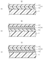
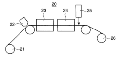
- FIG. 1 is a schematic cross-sectional view illustrating an example of an optical film 10. It is the schematic which shows the basic composition of the manufacturing apparatus 20 of an optical film. It is the schematic which shows the basic composition of the manufacturing apparatus 31 of the resin film by a solution casting method. It is the schematic which shows the basic composition of the manufacturing apparatus 41 of the resin film by a melt casting film forming method.
- An optical film according to an embodiment of the present invention includes a film substrate, a liquid crystal alignment layer formed on the film substrate, and a liquid crystal layer containing a liquid crystal compound formed on the liquid crystal alignment layer.
- the liquid crystal layer further contains a fluorosurfactant, and the fluorosurfactant is a copolymer having a lipophilic group, a hydrophilic group, and a fluoroaliphatic group. It is characterized by.
- the optical film is not particularly limited as long as it has the above configuration. Specifically, the optical film 10 provided with the layer structure shown in FIG. 1 etc. are mentioned, for example.
- the optical film 10 for example, as shown in FIG. 1A, a laminate in which a liquid crystal alignment layer 13 and a liquid crystal layer 14 are stacked on a film substrate 11. The thing which is is mentioned.
- the liquid crystal alignment layer 13 and the liquid crystal layer 14 are shown as the functional layer 12.
- a first intermediate layer 15 may be provided as the functional layer 12 between the liquid crystal alignment layer 13 and the liquid crystal layer 14.
- a second intermediate layer 16 may be provided between the film substrate 11 and the liquid crystal layer 14. Further, both the first intermediate layer 15 and the second intermediate layer 16 may be provided.
- the first intermediate layer 15 include an alignment film, an antistatic layer, and an antiglare layer.
- the second intermediate layer 16 include an antistatic layer, an elution suppressing layer, and an antiglare layer.
- the thickness of the optical film 10 is preferably 20 ⁇ m or more, and more preferably 20 to 80 ⁇ m.
- the thickness here means an average film thickness.
- the film thickness is measured at 20 to 200 locations in the width direction of the film with a contact-type film thickness meter manufactured by Mitutoyo Corporation, and the average value of the measured values is Defined as film thickness.
- the width, physical properties, shape, and the like of the film substrate 11 are not particularly limited and can be appropriately selected according to the purpose of the optical film to be manufactured. Although not particularly limited, the width of the optical film is large. From the viewpoint of use in a liquid crystal display device, use efficiency of a film during processing of a polarizing plate, and production efficiency, the thickness is preferably 1000 to 4000 mm.
- the optical film 10 preferably has an in-plane retardation Ro determined by the following formula (1) of 0 to 330 nm. Further, the thickness direction retardation Rt determined by the following formula (2) is preferably ⁇ 150 to 150 nm.
- nx represents the refractive index in the slow axis direction in the plane of the film
- ny represents the refractive index in the direction perpendicular to the slow axis in the plane of the film
- nz represents the thickness direction of the film.
- Refractive index is shown
- d shows the thickness (nm) of a film.
- Each refractive index can be measured at a wavelength of 590 nm in an environment of a temperature of 23 ° C. and a relative humidity of 55% RH using, for example, KOBRA-21ADH manufactured by Oji Scientific Instruments.
- the liquid crystal layer 14 contains a liquid crystal compound and a fluorosurfactant, and the fluorosurfactant is a copolymer having a lipophilic group, a hydrophilic group, and a fluoroaliphatic group. There is no particular limitation.
- the fluorosurfactant contained in the liquid crystal layer 14 is a copolymer having a lipophilic group, a hydrophilic group, and a fluoroaliphatic group in the side chain.
- a copolymer comprising a repeating unit derived from a lipophilic group-containing monomer, a repeating unit derived from a hydrophilic group-containing monomer, and a repeating unit derived from a fluoroaliphatic group-containing monomer. is there.
- the repeating unit constituting the main chain of the copolymer include polyolefin, polyether, polyester, polyamide, polyimide, polyurethane, polycarbonate, polysulfone, polyether, polyacetal, and polyketone.
- the main chain of the copolymer is preferably a polyolefin from the viewpoint of exerting the above-described effects of the lipophilic group, hydrophilic group and fluoroaliphatic group in the side chain.
- the lipophilic group is at least one selected from the group consisting of a cyclic or acyclic saturated alkyl group having 6 to 20 carbon atoms and a cyclic or acyclic saturated alkyloxy group having 6 to 20 carbon atoms. Preferably it is a seed.
- the saturated alkyl group and the saturated alkyloxy group are preferably not substituted with an alkyl group or another group other than the alkyloxy group.
- the saturated alkyl group and the saturated alkyloxy group may be linear or branched.
- the acyclic saturated alkyl group and the acyclic saturated alkyloxy group are more preferably a linear or branched saturated alkyl group and saturated alkyloxy group having 8 to 16 carbon atoms.
- the saturated alkyloxy group one or more hydrogens may be substituted with an alkoxyalkyl group.
- the cyclic saturated alkyl group is preferably a saturated alkyl group having a 5-membered to 8-membered monocycle, and the monocycle may be a monovalent group at the end of the alkyl group or a divalent group. Also good.
- the cyclic saturated alkyloxy group is preferably a saturated alkyloxy group having a 5- to 8-membered monocycle, and the monocycle may be a hydrocarbon ring or a heterocycle having oxygen as a heteroatom. It may be.
- the lipophilic group can effectively suppress the occurrence of coating unevenness when the liquid crystal layer 14 is applied on the liquid crystal alignment layer 13. This is considered to be because the compatibility of the liquid crystal compound contained in the liquid crystal layer coating liquid with the solvent liquid is enhanced by the lipophilic group.
- the hydrophilic group is preferably at least one selected from the group consisting of a carboxyl group, a salt thereof, a sulfo group, a salt thereof, a phosphonoxy group, a salt thereof, an onium salt, and a hydroxyl group.
- the carboxyl group salt, the sulfo group salt, or the phosphonoxy group salt include alkali metal salts, ammonium salts, and pyridinium salts.
- the onium salts include onium salts such as ammonium salts, sulfonium salts, and phosphonium salts. Preferred onium salts are quaternary ammonium salts.
- a carboxyl group salt, a sulfo group salt, or an onium salt is particularly preferable.
- the hydrophilic group can effectively suppress the occurrence of poor adhesion between the liquid crystal layer surface and the adhesive during the production of the polarizing plate. This is because the hydrophilic group promotes the formation of hydrogen bonds with, for example, the carbonyl group of the acrylic polymer contained in the liquid crystal alignment layer, and the fluorosurfactant tends to localize at the interface with the liquid crystal alignment layer. Therefore, it is considered that the localization to the liquid crystal layer air side interface can be suppressed.
- the fluoroaliphatic group is preferably an alkyl group having 1 to 12 carbon atoms and having a trifluoromethyl group or a difluoromethyl group at the terminal or a fluorine-substituted alkyl group.
- the fluorine-substituted alkyl group refers to an alkyl group in which an alkylene group other than the terminal trifluoromethyl group or difluoromethyl group is fluorine-substituted.
- the fluoroaliphatic group preferably has 6 to 10 carbon atoms, and the aliphatic group may be linear, branched or cyclic, and more preferably a linear alkyl group.
- the fluorine substitution of the alkylene group in the fluoroaliphatic group is more preferably one in which 50% or more of hydrogen in the alkylene group is substituted with fluorine, and hydrogen close to the terminal trifluoromethyl group or difluoromethyl group is selective. More preferably substituted with fluorine.
- the fluoroaliphatic group has the effect of enhancing the vertical alignment of the liquid crystal compound that coexists in the liquid crystal layer 14.
- the mass average molecular weight of the copolymer is preferably in the range of 1,000 to 500,000, and more preferably in the range of 10,000 to 200,000.
- the mass average molecular weight can be measured using, for example, gel permeation chromatography (GPC).
- fluorosurfactant that is, as a commercially available copolymer having the lipophilic group, the hydrophilic group, and the fluoroaliphatic group, specifically, examples thereof include F477 manufactured by DIC Corporation, which is an oligomer having a perfluoroalkyl group, a hydrophilic group, and a lipophilic group.
- the difference between the contact angle with water on the surface of the liquid crystal layer containing the fluorosurfactant and the contact angle with water on the surface of the liquid crystal layer not containing it is 10 ° or less. It is preferable that the angle is 7 ° or less.
- the difference between the contact angle with water on the surface of the liquid crystal layer containing the fluorosurfactant and the contact angle with water on the surface of the liquid crystal layer not containing the fluorosurfactant exceeds 10 °, the optical film is obtained. The adhesion failure between the liquid crystal layer surface of the polarizing plate and the pressure-sensitive adhesive tends to occur.
- the contact angle of water on the surface of the liquid crystal layer is measured, for example, as the contact angle 0.1 seconds after dropping a water droplet on the surface of the liquid crystal layer using an automatic contact angle meter (DCA-VZ type) manufactured by FACE. be able to.
- DCA-VZ type automatic contact angle meter
- the content ratio of the fluorosurfactant is preferably 0.01 to 1% by mass with respect to the liquid crystal compound.
- a more preferable content ratio is 0.05 to 0.8% by mass. If it is less than 0.01% by mass, the effect of suppressing coating unevenness due to the lipophilic group of the fluorosurfactant is difficult to appear, and if it exceeds 1% by mass, the adhesion between the liquid crystal layer surface and the pressure-sensitive adhesive tends to deteriorate.
- the liquid crystal layer 14 contains a liquid crystal compound in addition to the fluorine-based surfactant. It does not specifically limit as a liquid crystal compound,
- the conventionally well-known liquid crystal compound etc. which are contained in a liquid crystal layer are mentioned. Specifically, for example, those having a rod-like mesogen group or a disk-like mesogen group in the molecule can be mentioned. Among these, those having a rod-like mesogenic group in the molecule are preferable.
- said liquid crystal compound it can align so that the longitudinal direction of the molecule
- the liquid crystal layer 14 contains, for example, a liquid crystal compound having a rod-shaped mesogen group in the molecule, and the mesogen group has a major axis direction substantially perpendicular to the surface direction of the transparent film substrate. After the orientation (vertical orientation), the orientation is preferably fixed.
- the vertical alignment means that the tilt angle, which is the angle of the major axis direction of the mesogenic group (the alignment direction of the liquid crystal compound) with respect to the thickness direction of the film substrate, is 70 to 90 °. It is preferably 80 to 90 °.
- the liquid crystal compound is vertically aligned is known to depend on the structure of the liquid crystal compound, particularly the rod-shaped mesogenic group. That is, a liquid crystal compound having a vertically aligned structure can be vertically aligned by a known alignment process.
- the liquid crystal compound having a rod-shaped mesogen group in the molecule may be a polymerizable liquid crystal containing the rod-shaped mesogen group and a polymerizable functional group, and at least one of the main chain and the side chain.
- the polymer liquid crystal containing the rod-shaped mesogen group may be used, or the polymer liquid crystal containing the rod-shaped mesogen group and a polymerizable functional group may be used.
- the polymerizable functional group at the time of immobilization, for example, after cooling to less than the liquid crystal transition temperature, it is possible to further immobilize the orientation by polymerizing while cooling, This is preferable because it can be cured as an optically anisotropic layer.
- a polymerizable liquid crystal is preferable.
- the mesogenic group is not particularly limited, but is preferably a rod-like mesogenic group that can be vertically aligned. Specific examples include functional groups containing an ester group, a cyano group, an alkyl group, and an aryl group. Moreover, as said mesogenic group, 1 type of each said mesogenic group may be contained, and it may contain combining 2 or more types.
- the polymerizable functional group is not particularly limited, and it is preferable that polymerization can be performed while maintaining the orientation after the orientation.
- the polymerization may be initiated by heat, or the polymerization may be initiated by irradiation with active rays such as ultraviolet rays. That is, in the case of the polymerizable liquid crystal, it may be thermosetting or actinic ray curable.
- the liquid crystal compound is polymerized at a temperature lower than the liquid crystal transition temperature, it is preferable that the liquid crystal compound is not heated so much that an actinic ray curable one is more preferable.
- the polymerizable functional group examples include a vinyl group such as acryloyl group, methacryloyl group and vinyl ether, an epoxy group, and an oxetanyl group.
- the said polymerizable functional group may be used independently and may be used in combination of 2 or more type.
- the polymerizable liquid crystal may contain one polymerizable functional group in the molecule, or may contain two or more.
- the polymerizable functional group examples include an acryloyl group, a vinyl group such as methacryloyl group and vinyl ether, and an epoxy group.
- the said polymerizable functional group may be used independently and may be used in combination of 2 or more type.
- the polymerizable liquid crystal may contain one polymerizable functional group in the molecule, or may contain two or more.
- liquid crystal compound that are commercially available include UCL018 manufactured by DIC Corporation and Palio Color LC242 manufactured by BASF Corporation.
- a polymerizable liquid crystal having the polymerizable functional group is used as the liquid crystal compound in the liquid crystal layer forming composition used for forming the liquid crystal layer 14 according to the embodiment of the present invention.
- a photopolymerization initiator may be contained.
- a photopolymerization initiator is not required.
- polymerization generally used for example, polymerization by ultraviolet (UV) irradiation, the polymerization is promoted. Therefore, it is preferable to contain a photopolymerization initiator. By doing so, polymerization temperature can be made low and the said fixation can be performed suitably.
- the photopolymerization initiator is not particularly limited. Specifically, for example, benzyl (bibenzoyl), benzoin isobutyl ether, benzoin isopropyl ether, benzophenone, benzoylbenzoic acid, benzoylmethyl benzoate, 4-benzoyl-4 ′ -Methyldiphenyl sulfide, benzylmethyl ketal, dimethylaminomethylbenzoate, 2-n-butoxyethyl-4-dimethylaminobenzoate, isoamyl p-dimethylaminobenzoate, 3,3'-dimethyl-4-methoxybenzophenone, methylobenzoyl Formate, 2-methyl-1- (4- (methylthio) phenyl) -2-morpholinopropan-1-one, 2-benzyl-2-dimethylamino-1- (4-morpholinophenyl) -butane-1 -Oh 1- (4-dodecylphen
- the content of the photopolymerization initiator is preferably 0.01 to 20% by mass, more preferably 0.1 to 10% by mass, and further preferably 0.5 to 5% by mass. preferable. If the content of the photopolymerization initiator is too small, the effect of the photopolymerization initiator tends not to be exhibited. If the content is too large, the polymerizability of the liquid crystal compound is lowered and the molecular weight is lowered, so that the scratch resistance is reduced. There is a tendency for the sex etc. to decrease.
- the liquid crystal layer forming composition may contain a sensitizer as long as the object of the present invention is not impaired. Although it does not specifically limit as said sensitizer, Specifically, Nippon Kayaku Co., Ltd. Kayacure DETX etc. are mentioned, for example.
- a method of preparing a liquid liquid crystal layer forming composition containing a solvent and coating the liquid crystal layer forming composition on the liquid crystal alignment layer is preferable. Thereby, it is possible to more effectively utilize the effect of suppressing the occurrence of coating unevenness due to the fluorosurfactant contained in the liquid crystal layer.
- the solvent for the liquid crystal layer forming composition is not particularly limited as long as the liquid crystal compound can be dissolved. Moreover, it is preferable that it is a solvent which does not change the property etc. of a transparent film base material.
- hydrocarbons such as benzene, toluene, xylene, n-butylbenzene, diethylbenzene, and tetralin; ethers such as methoxybenzene, 1,2-dimethoxybenzene, and diethylene glycol dimethyl ether; acetone, methyl ethyl ketone, Ketones such as methyl isobutyl ketone, cyclohexanone, and 2,4-pentanedione; esters such as ethyl acetate, ethylene glycol monomethyl ether acetate, propylene glycol monomethyl ether acetate, propylene glycol monoethyl ether acetate, and ⁇ -butyrolactone; 2
- solvents for example, hydrocarbon solvents, glycol monoether acetate solvents and the like are preferable as the solvent used alone.
- solvents for example, hydrocarbon solvents, glycol monoether acetate solvents and the like are preferable as the solvent used alone.
- a combination of the solvent used in combination of 2 or more types a combination of ethers or ketones and glycols and the like can be mentioned.
- the solid content concentration of the composition for forming a liquid crystal layer varies depending on the solubility of a liquid crystal compound or the like, the film thickness of the liquid crystal layer to be produced, and the like. Preferably, it is 3 to 40% by mass.
- the following additive may be contained in the liquid crystal layer forming composition within the range not impairing the object of the present invention, in addition to the above-mentioned compositions.
- the content of the additive is selected within a range that does not impair the object of the present invention, and is generally preferably 40% by mass or less of the composition for forming a liquid crystal layer, and 20% by mass or less. It is preferable that
- composition for forming a liquid crystal layer containing a solvent may contain a surfactant other than the fluorine-based surfactant according to the present invention.
- a surfactant other than the fluorine-based surfactant according to the present invention.
- cationic surfactants such as imidazoline, quaternary ammonium salts, alkylamine oxides, polyamine derivatives; polyoxyethylene-polyoxypropylene condensates, primary or secondary alcohol ethoxylates , Alkylphenol ethoxylates, polyethylene glycol and its esters, sodium lauryl sulfate, ammonium lauryl sulfate, lauryl sulfate amines, alkyl-substituted aromatic sulfonates, alkyl phosphates, aliphatic or aromatic sulfonate formalin condensates, etc.
- amphoteric surfactants such as laurylamidopropylbetaine and laurylaminoacetic acid betaine
- nonionic surfactants such as polyethylene glycol fatty acid esters and polyoxyethylene alkylamine And the like. What is necessary is just to select content of surfactant suitably in the range which does not impair the effect of the said fluorosurfactant which concerns on this invention.
- the thickness of the liquid crystal layer 14 is preferably 0.1 to 10 ⁇ m, and more preferably 0.2 to 5 ⁇ m.
- the liquid crystal layer 14 preferably has an in-plane retardation Ro determined by the above formula (1) of 0 to 10 nm. Further, the thickness direction retardation Rt determined by the above formula (2) is preferably ⁇ 500 to ⁇ 100 nm.
- the liquid crystal alignment layer 13 that enhances the alignment of the liquid crystal compound is formed on the film substrate 11 or on the second intermediate layer 16 when the second intermediate layer 16 is provided.
- the liquid crystal alignment layer 13 may include, for example, a resin such as an actinic radiation curable resin and may be subjected to a rubbing process, or may include a resin such as an actinic radiation curable resin and the vertical alignment agent. May be.
- the actinic radiation curable resin may be any resin that can be cured by an actinic radiation such as ultraviolet rays. And those having a polymerizable functional group such as a group.
- the liquid crystal alignment layer according to the present invention preferably contains an acrylic polymer. The presence of the acrylic polymer in the liquid crystal alignment layer suppresses the occurrence of poor adhesion between the liquid crystal layer surface and the pressure-sensitive adhesive during the production of the polarizing plate, possessed by the hydrophilic group of the fluorosurfactant contained in the liquid crystal layer. This is because the effect is exhibited more effectively.
- the actinic radiation curable resin those having two or more polymerizable functional groups and having a crosslinked structure or a network structure when irradiated with actinic radiation are also preferable.
- the active ray is preferably ultraviolet rays from the viewpoint of workability. That is, the actinic radiation curable resin is preferably an ultraviolet curable resin.
- the liquid crystal alignment layer 13 contains not only the actinic radiation curable resin but also a cellulose ester resin, which indicates the adhesion between the upper layer of the liquid crystal alignment layer 13 and the lower layer of the liquid crystal alignment layer 13, specifically In particular, the adhesion with the liquid crystal layer 14 and the adhesion with the film substrate 11 can be enhanced, and in particular, the adhesion under high temperature and high humidity can be enhanced.
- the content is preferably 1 to 10 parts by mass with respect to 100 parts by mass of the actinic radiation curable resin.
- the cellulose-ester resin etc. which comprise a transparent film base material are mentioned. Specifically, what is illustrated below is mentioned as a cellulose-ester resin of a transparent film base material, for example.
- the thickness of the liquid crystal alignment layer 13 is preferably 1.2 to 3 ⁇ m. If it is too thin, it tends to be difficult to exert the effect of promoting the alignment of the liquid crystal compound in the liquid crystal layer 14 and the effect of improving the adhesion as described above. Furthermore, the effect of preventing the components of the film substrate 11 from eluting into the liquid crystal layer 14 also tends to be reduced. On the other hand, if the thickness is too thick, the resulting optical film becomes unnecessarily thick, which tends to hinder the thinning of the optical film.
- the film substrate 11 is not particularly limited as long as it has transparency and can be used as a substrate for an optical film.
- being transparent means that the transmittance of visible light is 60% or more, preferably 80% or more, and more preferably 90% or more.
- Specific examples of the film substrate 11 include a resin film having high transparency.
- the resin for the resin film include polyester resins such as cellulose ester resin, polyester resin, polycarbonate resin, polyarylate resin, polysulfone resin, polyethersulfone resin, polyethylene terephthalate resin, and polyethylene naphthalate resin.
- polyester resins such as cellulose ester resin, polyester resin, polycarbonate resin, polyarylate resin, polysulfone resin, polyethersulfone resin, polyethylene terephthalate resin, and polyethylene naphthalate resin.
- a cellulose ester film containing a cellulose ester resin is preferable.
- the resin film may contain a plasticizer and fine particles.
- the ultraviolet absorber may contain in the range which does not inhibit the hardening of the resin composition which is the raw material. The manufacturing method of the resin film which is such a film base material is mentioned later.
- the thickness of the film base 11 is preferably thinner in order to reduce the thickness of the optical film, but is preferably 20 ⁇ m or more in order to prevent breakage during production.
- the thickness here means an average film thickness.
- the film thickness is measured at 20 to 200 locations in the width direction of the film with a contact-type film thickness meter manufactured by Mitutoyo Corporation, and the average value of the measured values is Defined as film thickness.
- the width, physical properties, shape, and the like of the film substrate 11 are not particularly limited, and can be appropriately selected according to the purpose of the optical film to be manufactured. Although not particularly limited, the width of the optical film is large. From the viewpoint of use in a liquid crystal display device, use efficiency of a film at the time of polarizing plate processing, and production efficiency, the thickness is preferably from 1000 to 4000 mm.
- the film substrate 11 preferably has an in-plane retardation Ro determined by the above formula (1) of 0 to 330 nm. Further, the thickness direction retardation Rt determined by the above formula (2) is preferably ⁇ 100 to 340 nm.
- the optical film which concerns on one Embodiment of this invention is a liquid crystal alignment by irradiating an active ray to the process of apply
- a liquid crystal layer comprising: a step of forming the layer 13; a fluorosurfactant which is a copolymer having a lipophilic group, a hydrophilic group and a fluoroaliphatic group on the liquid crystal alignment layer; and a liquid crystal compound.
- a step of applying a forming composition, an alignment step of aligning the liquid crystal compound by heating the liquid crystal layer forming composition, and an immobilization step of forming a liquid crystal layer by fixing the aligned liquid crystal compound It can manufacture by a manufacturing method provided with these. Specifically, it is manufactured as follows. Here, as shown to Fig.1 (a), it consists only of the said film base material 11, the said liquid crystal aligning layer 13, and the said liquid crystal layer 14, and the said 1st intermediate
- a liquid crystal alignment layer 13 is formed on the film substrate 11.
- composition for forming a liquid crystal alignment layer containing the actinic radiation curable resin or the like is applied on the film substrate 11.
- the composition for forming a liquid crystal alignment layer may contain, for example, the cellulose ester resin, an organic solvent, a photopolymerization initiator, and the like in addition to the actinic radiation curable resin.
- the organic solvent is not particularly limited as long as it can dissolve the actinic radiation curable resin.
- alcohols such as isopropyl alcohol, ethers such as methylene chloride, dioxolane and propylene glycol monomethyl ether, esters such as ethyl acetate and methyl acetate, ketones such as acetone and methyl ethyl ketone, and diacetone alcohol Ketone alcohols and the like.
- alcohols such as isopropyl alcohol and ethers such as propylene glycol monomethyl ether are preferable, and a mixed solvent of isopropyl alcohol and propylene glycol monomethyl ether is more preferable.
- these may be used independently and may be used in combination of 2 or more type.
- the solid content concentration of the composition for forming a liquid crystal alignment layer varies depending on the composition and the like, but is preferably about 0.1 to 80% by mass, for example.
- the photopolymerization initiator it is only necessary to contribute to the initiation of the curing reaction of the actinic radiation curable resin.
- ⁇ -hydroxyketone, acetophenone, benzophenone, hydroxybenzophenone, Michler's ketone, ⁇ -amyloxime ester, thioxanthone And derivatives thereof are preferred.
- these may be used independently and may be used in combination of 2 or more type.
- the content of the photopolymerization initiator is preferably about 0.1 to 1 part by mass with respect to 100 parts by mass of the actinic radiation curable resin, for example.
- the coating method is not particularly limited, and a known coating method can be used. Specific examples include a gravure coater, a spinner coater, a wire bar coater, a roll coater, a reverse coater, an extrusion coater, an air doctor coater, a die coater, a dip coater, and an ink jet method. And as application
- the liquid crystal alignment layer 13 is formed by irradiating the composition for forming a liquid crystal alignment layer applied on the film substrate 11 with active rays.
- liquid crystal layer 14 is formed on the liquid crystal alignment layer 13.
- a liquid crystal layer forming composition containing the fluorosurfactant and a liquid crystal compound is applied on the liquid crystal alignment layer 13.
- the composition for forming a liquid crystal layer may contain, for example, an organic solvent, a photopolymerization initiator, and the like in addition to the fluorine-based surfactant and the liquid crystal compound.
- the organic solvent is not particularly limited as long as it can dissolve the fluorosurfactant and the liquid crystal compound.
- alcohols such as isopropyl alcohol, esters such as methylene chloride, dioxolane and propylene glycol monomethyl ether acetate, esters such as ethyl acetate and methyl acetate, ketones such as acetone and methyl ethyl ketone, and diacetone Examples include ketone alcohols such as alcohol.
- those having a relatively high boiling point such as propylene glycol monomethyl ether acetate are preferable.
- these may be used independently and may be used in combination of 2 or more type.
- the solid content concentration of the composition for forming a liquid crystal layer varies depending on the composition and the like, but is preferably about 0.1 to 80% by mass, for example.
- the photopolymerization initiator may be contained in the liquid crystal layer forming composition when a liquid crystal compound having a polymerizable functional group is used.
- the photopolymerization initiator is not limited as long as it can contribute to the initiation of the curing reaction of the liquid crystal compound, and examples thereof include the same photopolymerization initiators as the liquid crystal alignment layer forming composition. Examples thereof include ⁇ -hydroxyketone, acetophenone, benzophenone, hydroxybenzophenone, Michler's ketone, ⁇ -amyloxime ester, thioxanthone, and derivatives thereof. Of these, ⁇ -hydroxyketone and derivatives thereof are preferred. Moreover, these may be used independently and may be used in combination of 2 or more type.
- the content of the photopolymerization initiator is preferably about 0.1 to 1 part by mass with respect to 100 parts by mass of the photopolymerizable liquid crystal compound, for example.
- the coating method is not particularly limited, and a known coating method can be used, and the same coating method as the liquid crystal alignment layer forming composition can be used. Specific examples include a gravure coater, a spinner coater, a wire bar coater, a roll coater, a reverse coater, an extrusion coater, an air doctor coater, a die coater, a dip coater, and an ink jet method.
- the coating thickness varies depending on the solid content concentration of the liquid crystal layer forming composition, and specifically, for example, the thickness of the liquid crystal layer to be formed is within the above range. Is preferred.
- the liquid crystal compound is aligned by heating the liquid crystal layer forming composition applied on the liquid crystal alignment layer 13 to a temperature higher than the liquid crystal transition temperature of the liquid crystal compound.
- the alignment time takes about 1 to 10 minutes, for example.
- the composition for forming a liquid crystal layer is cooled below the liquid crystal transition temperature of the liquid crystal compound, the alignment is fixed, and the composition for forming a liquid crystal layer is irradiated with active rays. By doing so, the orientation is more fixed, and the liquid crystal layer 14 in which the liquid crystal compound is vertically aligned is formed.
- the formation of the functional layer 12 such as the liquid crystal alignment layer 13 or the liquid crystal layer 14 can be performed by, for example, an optical film manufacturing apparatus as shown in FIG. In addition, as an optical film manufacturing apparatus, it is not limited to what is shown in FIG. 2, The thing of another structure may be sufficient.
- FIG. 2 is a schematic diagram showing a basic configuration of the optical film manufacturing apparatus 20.
- the optical film manufacturing apparatus 20 includes an unwinding device 21, a coating device 22, a first temperature adjusting device 23, a second temperature adjusting device 24, a curing device 25, a winding device 26, and the like.
- the unwinding device 21 supplies a film to be processed such as a transparent film substrate to the coating device 22 and the like.
- the unwinding device 21 includes, for example, an unwinding roller wound so that the film to be processed can be unwound, and supplies the film to be processed to the coating device 22 and the like by rotating the unwinding roller. is there.
- the coating device 22 applies a liquid crystal alignment layer forming composition or a liquid crystal layer forming composition on the surface of the film to be processed supplied from the unwinding device 21.
- the coating device 21 can use a general coating device without limitation. Specifically, for example, the above-described coating apparatus and the like can be mentioned.
- the coating may be simultaneously applied in multiple layers with a single application device such as an extrusion die having a multi-manifold.
- a plurality of apparatuses may be arranged side by side and applied sequentially.
- the first temperature adjusting device 23 heats and drys the liquid crystal alignment layer forming composition applied on the film to be processed.
- the liquid crystal layer forming composition applied on the film to be processed is heated to align the liquid crystal compound in the liquid crystal layer forming composition.
- the first temperature control device 23 may employ, for example, a convection drying method using hot air, a radiant drying method using radiant heat such as infrared rays, or the like.
- the liquid crystal alignment layer forming composition applied on the film to be processed is cooled to form a liquid crystal alignment layer forming composition before curing.
- the liquid crystal layer forming composition applied on the film to be treated is cooled, and not only the fluidity of the liquid crystal layer forming composition before curing is lowered, but also the liquid crystal layer forming The liquid crystal compound in the composition is fixed.
- the second temperature adjusting device 24 may employ, for example, a convection drying method using cold air.
- the curing device 25 is applied on a film to be processed, and the composition subjected to the above treatment is irradiated with active rays to be cured.
- active ray irradiation apparatuses such as an ultraviolet irradiation apparatus, are mentioned, for example.
- the winding device 26 winds up the optical film obtained as described above.
- the winding device 26 is, for example, a device that includes a rotatable winding roller and winds the optical film by rotating the winding roller.
- the film substrate is not particularly limited as long as it can be used as a substrate for an optical film.
- a resin film obtained by a solution casting film forming method or a melt casting film forming method described later can be used, and a resin film obtained by a melt casting film forming method is preferable. Used. If it is such a resin film, a film thickness is uniform and it can be conveniently used as a base material of an optical film.
- the manufacturing method of the cellulose-ester film which is a resin film suitable as a film base material is demonstrated here.
- the solution casting film forming method includes a casting step in which a resin solution (dope) in which a transparent resin is dissolved is cast on a traveling support to form a casting film (web), and the casting film is
- a film forming method comprising a peeling step for peeling from the support as a film, a stretching step for stretching the peeled film, and a drying step for drying the film by transporting the stretched film with a plurality of transport rollers. is there.
- it is performed by a resin film manufacturing apparatus using a solution casting film forming method as shown in FIG.
- a manufacturing apparatus of a resin film it is not limited to what is shown in FIG. 3, The thing of another structure may be sufficient.
- FIG. 3 is a schematic diagram showing a basic configuration of a resin film manufacturing apparatus 31 by a solution casting method.
- the resin film manufacturing apparatus 31 includes an endless belt support 32, a casting die 33, a peeling roller 34, a stretching apparatus 35, a drying apparatus 36, a winding apparatus 37, and the like.
- the casting die 13 casts a resin solution (dope) 38 in which a transparent resin is dissolved on the surface of the endless belt support 32.
- the endless belt support 32 is formed into a film by forming a web made of the dope 38 cast from the casting die 33 and drying it while being conveyed.
- the peeling roller 34 peels the film from the endless belt support 32.
- the stretching device 35 stretches the peeled film.
- the drying device 36 dries the stretched film while being conveyed by a conveyance roller.
- the winding device 37 winds the dried film into a film roll.
- the dope is supplied to the casting die 33 from a dope supply pipe connected to the upper end. Then, the supplied dope is discharged from the casting die 33 to the endless belt support 32, and a web is formed on the endless belt support 32.
- the endless belt support 32 is a metal endless belt having a mirror surface and traveling infinitely.
- a belt made of stainless steel or the like is preferably used from the viewpoint of peelability of the film.
- the width of the cast film cast by the casting die 33 is preferably 80 to 99% with respect to the width of the endless belt support 32.
- the width of the endless belt support 32 is preferably 1800 to 5000 mm.
- a rotating metal drum (endless drum support) having a mirror surface may be used instead of the endless belt support.
- the endless belt support 32 dries the solvent in the dope while conveying the cast film (web) formed on the surface thereof.
- the drying is performed, for example, by heating the endless belt support 32 or blowing heated air onto the web.
- the temperature of the web varies depending on the dope solution, the range of ⁇ 5 to 70 ° C. is preferable and the range of 0 to 60 ° C. is preferable in consideration of the conveyance speed and productivity accompanying the evaporation time of the solvent. More preferred.
- the higher the temperature of the web the faster the solvent can be dried. However, when the temperature is too high, the web tends to foam or the flatness tends to deteriorate.
- a method of heating the web on the endless belt support 32 with an infrared heater for example, a method of heating the back surface of the endless belt support 32 with an infrared heater, the back surface of the endless belt support 32 And a method of heating by blowing heated air, and the like can be selected as needed.
- the wind pressure of the heated air is preferably 50 to 5000 Pa in consideration of the uniformity of solvent evaporation and the like.
- the temperature of the heating air may be dried at a constant temperature, or may be supplied in several steps in the running direction of the endless belt support 32.
- the time from casting the dope on the endless belt support 32 to peeling the web from the endless belt support 32 varies depending on the film thickness of the resin film to be produced and the solvent used. Considering the peelability from the belt support 32, it is preferably in the range of 0.5 to 5 minutes.
- the conveying speed of the cast film by the endless belt support 32 is preferably about 50 to 200 m / min, for example. Further, the ratio (draft ratio) of the casting film conveyance speed to the traveling speed of the endless belt support 32 is preferably about 0.8 to 1.2. When the draft ratio is within this range, the cast film can be stably formed. For example, if the draft ratio is too large, there is a tendency to cause a phenomenon called neck-in in which the cast film is reduced in the width direction, and if so, a wide film cannot be formed.
- the peeling roller 34 is in contact with the surface of the endless belt support 32 on which the dope 38 is cast, and the dried web (film) is peeled by applying pressure to the endless belt support 32 side. .
- the film is peeled from the endless belt support 32, the film is stretched in the film transport direction (machine direction: MD direction) by the peeling tension and the subsequent transport tension. For this reason, it is preferable that the peeling tension and the conveying tension when peeling the film from the endless belt support 32 are 50 to 400 N / m.
- the total residual solvent amount of the film when the film is peeled off from the endless belt support 32 is the peelability from the endless belt support 32, the residual solvent amount at the time of peeling, the transportability after peeling, and the result after transporting and drying.
- the physical properties of the resin film and the like it is preferably 30 to 200% by mass.
- the stretching device 35 stretches the film peeled from the endless belt support 32 in a direction (Transverse Direction: TD direction) orthogonal to the web conveyance direction. Specifically, both ends in a direction perpendicular to the film transport direction are gripped with a clip or the like, and the distance between the opposing clips is increased to extend in the TD direction. And the said extending
- the drying device 36 includes a plurality of transport rollers, and dries the film while transporting the film between the rollers. In that case, you may dry using heating air, infrared rays, etc. independently, and you may dry using heating air and infrared rays together. It is preferable to use heated air from the viewpoint of simplicity.
- the drying temperature varies depending on the amount of residual solvent in the film. However, the drying temperature is appropriately selected depending on the amount of residual solvent in the range of 30 to 180 ° C. in consideration of drying time, unevenness of shrinkage, stability of the amount of expansion and contraction, etc. That's fine. Further, it may be dried at a constant temperature, or may be divided into two to four stages of temperature and may be divided into several stages of temperature.
- the film can be stretched in the MD direction while being conveyed in the drying device 36.
- the amount of residual solvent in the film after the drying treatment in the drying device 36 is preferably 0.01 to 15% by mass in consideration of the load of the drying process, the dimensional stability expansion / contraction ratio during storage, and the like.
- the winding device 37 winds the film having a predetermined residual solvent amount on the winding core to a required length by the drying device 36.
- the temperature at the time of winding is preferably cooled to room temperature in order to prevent scratches and loosening due to shrinkage after winding.
- the winder to be used can be used without particular limitation, and may be a commonly used one, such as a constant tension method, a constant torque method, a taper tension method, or a program tension control method with a constant internal stress. Can be wound up.
- the resin film that can be used as the film substrate according to the embodiment of the present invention is obtained through the above-described steps.
- the resin contained in the resin solution is not particularly limited as long as it is a resin having transparency when formed into a substrate by a solution casting film forming method or the like, but can be manufactured by a solution casting film forming method or the like. It is preferable that it is easy, has excellent adhesion to a liquid crystal alignment layer, and is optically isotropic.
- Specific examples of the transparent resin include cellulose ester resins such as cellulose triacetate resin.
- the dope used in the solution casting film forming method may contain fine particles. In this case, the fine particles to be used are appropriately selected according to the purpose of use, but are preferably fine particles that can scatter visible light when contained in a transparent resin.
- the fine particles may be inorganic fine particles such as silicon oxide or organic fine particles such as acrylic resin.
- a solvent containing a good solvent for the transparent resin can be used, and a poor solvent may be contained within a range in which the transparent resin does not precipitate.
- the good solvent for the cellulose ester resin include organic halogen compounds such as methylene chloride.
- the poor solvent for the cellulose ester resin include alcohols having 1 to 8 carbon atoms such as methanol.
- the resin solution used in the solution casting film forming method may contain other components (additives) other than the transparent resin, fine particles, and solvent as long as the effects of the present invention are not impaired.
- the additive include a plasticizer, an antioxidant, an ultraviolet absorber, a heat stabilizer, a conductive substance, a flame retardant, a lubricant, and a matting agent.
- a cellulose ester resin solution can be obtained by mixing the above-mentioned compositions.
- the obtained cellulose ester resin solution is preferably filtered using a suitable filter medium such as filter paper.
- melt casting method Next, the case where a resin film is manufactured by the melt casting method will be described.
- the melt casting film forming method includes a casting step of casting a resin melt obtained by melting a transparent resin on a traveling support to form a casting film, and cooling the casting film to form a film.
- a film forming method comprising: a cooling step for forming a film; a peeling step for peeling the film from the support; and a stretching step for stretching the film by transporting the peeled film with a plurality of transport rollers.
- it is performed by a resin film manufacturing apparatus using a melt casting film forming method as shown in FIG.
- a manufacturing apparatus of a resin film it is not limited to what is shown in FIG. 4, The thing of another structure may be sufficient.
- FIG. 4 is a schematic diagram showing a basic configuration of a resin film manufacturing apparatus 41 by a melt casting film forming method.
- the resin film manufacturing apparatus 41 includes a first cooling roller 42, a casting die 43, a touch roller 44, a second cooling roller 45, a third cooling roller 46, a peeling roller 47, a conveying roller 48, a stretching device 49, and a winding device.
- the apparatus 50 etc. are provided.
- the casting die 43 casts a resin melt (dope) obtained by melting a transparent resin onto the surface of the first cooling roller 42.
- the first cooling roller 42 forms a casting film made of a dope cast from the casting die 43, cools the casting film while transporting it, and transports the casting film to the second cooling roller 45.
- the thickness of the cast film is adjusted and the surface is smoothed by the touch roller 44 provided in contact with the first cooling roller 42.
- the second cooling roller 45 cools the cast film while transporting the cast film, and transports the cast film to the third cooling roller 46. By so doing, the cast film is used as a film.
- the peeling roller 47 peels the film from the third cooling roller 46.
- the transport roller 48 extends in the MD direction while transporting the peeled film.
- the stretching device 49 stretches the film in the TD direction.
- the winding device 50 winds the cooled and solidified film to form a film roll.
- the casting die 43 has the same configuration as the casting die 33 except that a resin melt is discharged as a dope instead of the resin solution.
- the first cooling roller 42, the second cooling roller 45, and the third cooling roller 46 are metal rollers having a mirror surface.
- a roller made of stainless steel or the like is preferably used from the viewpoint of peelability of a cast film or a film.
- the touch roller 44 has an elastic surface, and is deformed along the surface of the first cooling roller 42 by the pressing force to the first cooling roller 42, and between the first cooling roller 42, Form a nip.
- the touch roller 44 is not particularly limited as long as it is a touch roller conventionally used in the melt casting film forming method. Specifically, the thing made from stainless steel is mentioned, for example.
- the peeling roller 47 is in contact with the third cooling roller 46, and the film is peeled by pressurization.
- the transport roller 48 is composed of a plurality of transport rollers, and can be stretched in the MD direction of the film by setting a different rotational speed for each transport roller.
- the stretching device 49 and the winding device 50 may be the same as the stretching device 35 and the winding device 37 in the solution casting film forming method.
- the same resin as that used in the melt casting film forming method can be used as long as it can be heated and melted.
- the same composition as in the melt casting film forming method can be used for other compositions.
- the film substrate is not limited to the resin film formed by the solution casting film forming method or the melt casting film forming method, and may be a resin film formed by other methods, The resin film which laminated
- the film base material is a film formed by casting a resin melt containing the transparent resin and a plasticizer on a traveling support and cooling the cast film.
- a resin film obtained by peeling from a support, that is, a resin film formed by a melt casting method is preferable.
- a polarizing plate according to another embodiment of the present invention includes a polarizing element and a protective film disposed on a surface of the polarizing element, and the optical film according to the embodiment of the present invention is the protective film. Used.
- the polarizing element is an optical element that emits incident light by converting it into polarized light.
- polarizing plate for example, a completely saponified polyvinyl alcohol aqueous solution is used on at least one surface of a polarizing element produced by immersing and stretching a polyvinyl alcohol film in an iodine solution.
- a laminate is preferred.
- the said optical film may be laminated
- the transparent protective film for this polarizing plate for example, commercially available cellulose ester films such as KC8UX2M, KC4UX, KC5UX, KC4UY, KC8UY, KC12UR, KC8UY-HA, KC8UX-RHA, KC4FR-1, KC4HR-1, KC8UCR- 3, KC8UCR-4, KC8UCR-5, KC4UESW (manufactured by Konica Minolta Opto Co., Ltd.) and the like are preferably used.
- resin films such as cyclic olefin resin other than a cellulose-ester film, an acrylic resin, polyester, a polycarbonate. In this case, since the saponification suitability is low, it is preferable to perform an adhesive process on the polarizing plate through an appropriate adhesive layer.
- the polarizing plate uses the optical film as a protective film laminated on at least one surface side of the polarizing element.
- the optical film functions as an optical compensation film such as a retardation film
- the optical film is preferably disposed so that the slow axis of the optical film is substantially parallel or orthogonal to the absorption axis of the polarizing element.
- polarizing element examples include, for example, a polyvinyl alcohol polarizing film.
- Polyvinyl alcohol polarizing films include those obtained by dyeing iodine on polyvinyl alcohol films and those obtained by dyeing dichroic dyes.
- a modified polyvinyl alcohol film modified with ethylene is preferably used as the polyvinyl alcohol film.
- the polarizing element is obtained as follows, for example. First, a film is formed using a polyvinyl alcohol aqueous solution. The obtained polyvinyl alcohol film is uniaxially stretched and then dyed or dyed and then uniaxially stretched. And preferably, a durability treatment is performed with a boron compound.
- the film thickness of the polarizing element is preferably 5 to 40 ⁇ m, more preferably 5 to 30 ⁇ m, and even more preferably 5 to 20 ⁇ m.
- a cellulose ester-based optical film containing cellulose ester is bonded to the surface of the polarizing element, it is preferable to bond the cellulose ester optical film with a water-based adhesive mainly composed of completely saponified polyvinyl alcohol. Moreover, in the case of optical films other than a cellulose ester-type optical film, it is preferable to perform an adhesive process on a polarizing plate through an appropriate adhesive layer.
- the polarizing plate as described above is excellent in optical compensation performance and the like. It is done. Furthermore, since the optical anisotropic layer of the optical film has high adhesion, a polarizing plate is obtained in which the excellent optical compensation performance is maintained even in a poor environment such as high temperature and high humidity. It is done.
- a liquid crystal display device includes a liquid crystal cell and two polarizing plates arranged so as to sandwich the liquid crystal cell, and at least one of the two polarizing plates includes: The polarizing plate.
- the liquid crystal cell is a cell in which a liquid crystal substance is filled between a pair of electrodes, and by applying a voltage to the electrodes, the alignment state of the liquid crystal is changed and the amount of transmitted light is controlled. Since such a liquid crystal display device uses a polarizing plate excellent in optical compensation performance and the like, optical characteristics such as viewing angle characteristics of the liquid crystal display device can be improved. Therefore, high definition of the liquid crystal display device can be realized.
- liquid crystal display device examples include a reflective type, a transmissive type, and a transflective type, and also include a TN type, STN type, OCB type, HAN type, VA type (PVA). Type, MVA type), IPS type and the like.
- the polarizing plate provided with the optical film according to the present embodiment is preferably used in an IPS liquid crystal display device.
- a polarizing plate provided with the optical film according to the present embodiment into a commercially available IPS (In Plane Switching) mode liquid crystal display device, it has excellent visibility, excellent color shift, corner unevenness, and front contrast characteristics.
- IPS In Plane Switching
- the liquid crystal display device of the present invention can be manufactured.
- the IPS mode also includes a fringe-field switching (FFS) mode, and, like the IPS mode, a polarizing plate including the optical film according to the present embodiment can be incorporated.
- FFS fringe-field switching
- a liquid crystal display device having can be manufactured.
- the liquid crystal layer of the liquid crystal panel in the IPS mode type liquid crystal display device is homogeneously aligned in parallel with the substrate surface in the initial state, and the director of the liquid crystal layer in the plane parallel to the substrate is parallel to the electrode wiring direction when no voltage is applied. Or somewhat have an angle. Then, the direction of the director of the liquid crystal layer when the voltage is applied shifts to the direction perpendicular to the electrode wiring direction with the application of the voltage, and the director direction of the liquid crystal layer is compared with the direction of the director when no voltage is applied.
- the liquid crystal layer when the voltage is applied rotates the azimuth angle of the polarization by 90 ° like a half-wave plate, and the transmission axis of the output side deflection plate and the azimuth angle of the polarization Match and the display is white.
- the polarizing plate provided with the optical film according to the present embodiment can be used for a large-sized liquid crystal television.
- the screen size it can be used for 17 types or more, and can be suitably used from 26 types to about 100 types.
- the pressure is reduced to 100 ⁇ 10 2 Pa at 200 to 230 ° C., and finally the pressure is reduced to 4 ⁇ 10 2 Pa or less to remove the distillate, followed by filtration to remove the aromatic terminal ester compound ( A plasticizer) was obtained.
- a film substrate was produced by a melt casting film forming method.
- the obtained mixture was melt-mixed at 235 ° C. using a twin-screw extruder and pelletized.
- the cellulose ester film was formed by the manufacturing apparatus shown in FIG. Using a single screw extruder, pellets (moisture content 50 ppm) were melt-extruded from a T die, which is a casting die, onto a first cooling roller having a surface temperature of 100 ° C. at a melting temperature of 245 ° C. to form an initial film thickness. A cast film of 128 ⁇ m and a width of 1.0 m was obtained at a length of 35 m / min.
- the film was pressed on the first cooling roller with an elastic touch roller having a 2 mm thick metal surface.
- the obtained film was first stretched at 195 ° C. in the film-forming direction at a stretching rate of 1000% / min at 195 ° C. at a stretching rate of 1000% / min by a stretching machine using a roller peripheral speed difference to obtain a 40 ⁇ m-thick cellulose ester film.
- a preheating zone a stretching zone, a holding zone, and a cooling zone (a neutral zone for ensuring thermal insulation between the zones is also provided between the zones).
- a stretching zone at 165 ° C. in a stretching zone the film was cooled to 30 ° C., released from the clip, and the clip holding part was cut off to obtain a film substrate (cellulose ester film).
- the retardation value of the cellulose ester film As for the retardation value of the cellulose ester film, Ro was 71 nm and Rt was 160 nm.
- the retardation value is a value measured at a wavelength of 590 nm using an automatic birefringence meter KOBRA-21ADH (Oji Scientific Instruments) after adjusting the humidity to 23 ° C. and 55% RH.
- a composition for forming a liquid crystal alignment layer (liquid crystal alignment layer coating solution) having the following composition was applied on a cellulose ester film by die coating, dried at 80 ° C. for 30 seconds, and then an oxygen concentration of 2.0 vol%. Under the irradiation, ultraviolet rays were irradiated at an irradiation amount of 120 mJ / cm 2 and an illuminance of 200 mW / cm 2 to be cured. The film thickness of the liquid crystal alignment layer after curing was 2.0 ⁇ m.
- composition of liquid crystal alignment layer coating solution Polyester acrylate (Ralomer LR8800 manufactured by BASF Japan Ltd.) 25 parts by mass Propylene glycol monomethyl ether 290 parts by mass Isopropyl alcohol 685 parts by mass Photopolymerization initiator (Irgacure 184 manufactured by Ciba Japan Co., Ltd.) 0.05 part by mass [Example 1]
- a composition for forming a liquid crystal layer (liquid crystal layer coating solution) having the following composition was applied by a die coat to a thickness of 7 ⁇ m. After drying at 100 ° C. for 30 seconds, the mixture was heated for 30 seconds. Thereby, the liquid crystal compound in the liquid crystal layer coating solution was aligned.
- the film in which the liquid crystal compound was oriented was cured by irradiating with ultraviolet rays at an irradiation amount of 250 mJ / cm 2 and an illuminance of 300 mW / cm 2 .
- the thickness of the liquid crystal layer was 1.6 ⁇ m.
- the optical film thus obtained (including a film substrate, the liquid crystal alignment layer provided thereon, and the liquid crystal layer provided on the liquid crystal alignment layer) was designated as an optical film 1.
- Ro was 71 nm and Rt was -11 nm.
- UV polymerizable liquid crystal material UCL-018 manufactured by DIC Corporation
- Propylene glycol monomethyl ether acetate 80 parts by mass
- Photopolymerization initiator Irgacure 184 manufactured by Ciba Japan Co., Ltd.
- Fluorosurfactant F477 manufactured by DIC Corporation
- the fluorosurfactant is composed of a lipophilic group, a hydrophilic group, and a perfluoroalkyl group. Is a copolymer oligomer having in the side chain.
- This fluorosurfactant is a copolymer oligomer having a hydrophilic group and a perfluoroalkyl group in the side chain, and does not have a lipophilic group in the side chain.
- This fluorosurfactant (F487) is an oligomer of a copolymer having a lipophilic group and a perfluoroalkyl group in the side chain, and does not have a hydrophilic group in the side chain.
- a peelable protective film (PET) was pasted on the liquid crystal layer of each optical film (optical films 1 to 3) according to Example 1 and Comparative Examples 1 and 2.
- a peelable protective film (PET) was attached to one side of a commercially available film (KC4UYSW manufactured by Konica Minolta Opto Co., Ltd.).
- the alkali saponification process was implemented to the optical film and commercial film which affixed the protective film.
- the alkali saponification treatment was performed in the order of a saponification step, a first water washing step, a neutralization step, a second water washing step, and a drying step. Thereby, the surface of each optical film and the commercially available film on which the protective film was not attached was subjected to alkali saponification treatment.
- the conditions for the alkali saponification treatment were specifically immersed in 2.5 M NaOH at a liquid temperature of 50 ° C. for 90 seconds as the saponification step.
- As a 1st water washing process it washed with water for 45 seconds with water with a liquid temperature of 30 degreeC.
- As a neutralization step the solution was neutralized with 10% by mass HCl having a liquid temperature of 30 ° C. for 45 seconds.
- As a 2nd water washing process it washed with water with the liquid temperature of 30 degreeC for 45 second. And as a drying process, it was made to dry until a film dried completely at 80 degreeC.
- the polarizing film was subjected to alkali saponification treatment so that the transmission axis of the produced polarizing film and the in-plane slow axis of the film were parallel to each other.
- the polarizing plates provided with any one of the optical films 1 to 3 were prepared by bonding the surfaces and bonding the surface of the other commercial film that had been subjected to alkali saponification treatment.
- the in-plane retardation Ro of each optical film was measured with an in-plane slow axis of the optical film inclined by 40 °.
- the measurement area was 5 cm ⁇ 5 cm, and a total of 10,000 points were measured at a pitch of 0.5 mm, and the standard deviation was obtained. From the result, it was evaluated that the smaller the standard deviation, the less the coating unevenness.
- the liquid crystal layer surface of the polarizing plate prepared using each optical film and the glass were bonded with an adhesive tape (Nitto Denko Corporation No. 31B), and left for 2 weeks in an environment of 80 ° C. and 90% RH, and then visually. Then, the bonded state was evaluated according to the following criteria.
- Table 1 shows the obtained results for coating unevenness and adhesiveness.
- Table 1 shows the difference between the contact angle with respect to water on the liquid crystal layer surface of the optical films 1 to 3 and the contact angle with respect to water on the liquid crystal layer surface of the optical film containing no fluorosurfactant.
- the optical film 1 (Example 1) containing a fluorosurfactant, which is an oligomer having a lipophilic group, a hydrophilic group, and a perfluoroalkyl group, in the liquid crystal layer has a hydrophilic group
- optical film 2 (Comparative Example 1) containing a fluorosurfactant in the liquid crystal layer, which is an oligomer having a perfluoroalkyl group but not having a lipophilic group
- optical film 1 (Example 1) containing a fluorosurfactant having a lipophilic group, a hydrophilic group, and a perfluoroalkyl group in the liquid crystal layer is hydrophilic although it has a lipophilic group and a perfluoroalkyl group.
- optical film 3 (Comparative Example 2) containing a fluorosurfactant, which is an oligomer having no functional group, in the liquid crystal layer, it is effective in producing poor adhesion between the liquid crystal layer surface and the pressure-sensitive adhesive during the production of the polarizing plate. Can be suppressed.
- the optical film it can be seen that the adhesion between the liquid crystal layer surface of the polarizing plate produced from the above and the pressure-sensitive adhesive can be improved.
- the polarizing plate produced from the optical film 1 which contains the fluorine-type surfactant which is an oligomer which has a lipophilic group, a hydrophilic group, and a perfluoroalkyl group in a liquid crystal layer has favorable contrast, and was excellent in display. Showed sex. Thereby, it was confirmed that it is excellent as a polarizing plate for an image display device such as a liquid crystal display.
Landscapes
- Physics & Mathematics (AREA)
- Chemical & Material Sciences (AREA)
- Crystallography & Structural Chemistry (AREA)
- General Physics & Mathematics (AREA)
- Optics & Photonics (AREA)
- Polarising Elements (AREA)
- Laminated Bodies (AREA)
Abstract
液晶配向層の上に液晶層を塗布する際の塗布性が改良され、かつ液晶層面と粘着剤との接着性に優れた光学フィルムを提供することを目的とする。また、そのような光学フィルムを保護フィルムとして用いた偏光板、及び前記偏光板を備えた液晶表示装置を提供することを目的とする。フィルム基材11と、前記フィルム基材11の上に形成された液晶配向層13と、前記液晶配向層13の上に形成された、液晶化合物を含有する液晶層14を備え、前記液晶層14は、さらにフッ素系界面活性剤を含有し、前記フッ素系界面活性剤は、親油性基と、親水性基と、フルオロ脂肪族基とを有する共重合体であることを特徴とする光学フィルムである。
Description
本発明は、光学フィルム、前記光学フィルムを保護フィルムとして用いた偏光板、及び前記偏光板を備えた液晶表示装置に関する。
液晶表示装置は、例えば、視野角特性等の光学特性を改善するために、光学補償性能を有する光学フィルムが使用されている。このような光学フィルムとしては、液晶化合物を含有し、その液晶化合物が配向して光学異方性をもつ液晶層を備えた光学フィルムが知られている。そして、そのような液晶層(光学異方性層ともいう)を形成する方法としては、透明性フィルム基材等の上に、まず、液晶層に含有される液晶化合物の配向性を高める液晶配向層形成用組成物を塗布し、紫外線を照射して硬化させて液晶配向層を形成する工程と、次に、前記液晶配向層の上に、液晶化合物を含有する液晶層形成用組成物を塗布し、前記液晶化合物を配向させた後、その配向を固定して液晶層を形成する工程とを備えるものが一般的である。
一方、上記のように、液晶配向層の上に塗布することにより形成された液晶層を備える光学フィルムは、液晶層に含まれる液晶化合物の垂直配向性が損なわれるおそれがあることが知られている。このため、例えば特許文献1においては、フルオロ脂肪族基含有化合物およびオニウム塩の存在下で、液晶性化合物の分子を配向させることによって、特にディスコティック液晶性化合物の垂直配向性を向上させることができる、との報告がなされている。
また、光学異方性層を塗布して得られる光学フィルムの光漏れムラを抑えるため、例えば特許文献2においては、光学異方性層中にフルオロ脂肪族基含有共重合体を共存させることが提案されている。
さらに、液晶層を高速塗布することにより発生する塗布ムラを抑えるため、例えば特許文献3においては、液晶性化合物を含有する塗布液中にフルオロ脂肪族基含有ポリマーを含有させることが提案されている。
特許文献1によれば、フルオロ脂肪族基と親水性基とを含む化合物、オニウム塩および、液晶性化合物を含有する組成物から光学異方性層を形成することにより、光学異方性層中の液晶性化合物の分子を実質的に垂直配向させることができる旨が開示されている。
しかしながら、本発明者等の試験によれば、このような組成物は、液晶性化合物の垂直配向性を向上させることはできるかもしれないが、光学異方性層を高速塗布して得られる光学フィルムにおいて塗布ムラを発生させて塗布性を低下させることがわかった。
一方、特許文献2あるいは特許文献3において提案されているフルオロ脂肪族基含有共重合体あるいはフルオロ脂肪族基含有ポリマーは、本発明者等の試験によれば、得られる光学フィルムから作製された偏光板の液晶層面と粘着剤との接着を不十分なものとし、そのため加熱や加湿によって液晶層面が剥がれてしまうことがわかった。
本発明は、かかる事情に鑑みてなされたものであり、液晶配向層の上に液晶層を塗布する際の塗布性が改良され、かつ液晶層面と粘着剤との接着性に優れた光学フィルムを提供することを目的とする。また、そのような光学フィルムを保護フィルムとして用いた偏光板、及び前記偏光板を備えた液晶表示装置を提供することを目的とする。
本発明の一態様に係る光学フィルムは、フィルム基材と、前記フィルム基材の上に形成された液晶配向層と、前記液晶配向層の上に形成された、液晶化合物を含有する液晶層とを備え、前記液晶層は、さらにフッ素系界面活性剤を含有し、前記フッ素系界面活性剤は、親油性基と、親水性基と、フルオロ脂肪族基とを有する共重合体であることを特徴とするものである。
液晶層に含まれるフッ素系界面活性剤は、親油性基が、液晶配向層の上に液晶層を塗布する際の塗布性の改良に寄与し、親水性基が液晶層面と粘着剤との接着性を良好なものとする作用効果を有する。これにより、液晶層を塗布する際の塗布性と、液晶層面と粘着剤との接着性に優れた光学フィルムを提供することができる。
また、フッ素系界面活性剤を含有する液晶層の表面における水に対する接触角と、それを含有しない液晶層の表面における水に対する接触角との差は、10°以下であることが好ましい。
この構成により、得られる光学フィルムから作製された偏光板の液晶層面と粘着剤との接着性をさらに向上させることができる。
さらに、親油性基は、炭素数6~20の、環式または非環式の飽和アルキル基、および炭素数6~20の、環式または非環式の飽和アルキルオキシ基からなる群から選ばれる少なくとも1種であることが好ましい。
前記親油性基は、液晶配向層の上に液晶層を塗布する際の塗布ムラの発生を効果的に抑えることができる。
また、親水性基は、カルボキシル基、その塩、スルホ基、その塩、ホスホノキシ基、その塩、オニウム塩、およびヒドロキシル基からなる群から選ばれる少なくとも1種であることが好ましい。
前記親水性基は、偏光板作製時の液晶層面と粘着剤との接着不良の発生を効果的に抑えることができる。
さらに、フルオロ脂肪族基は、炭素数1~12の、末端にトリフルオロメチル基またはジフルオロメチル基を有するアルキル基またはフッ素置換アルキル基であることが好ましい。
前記フルオロ脂肪族基は、液晶層に共存する液晶化合物の垂直配向性を高めることができる。
また、フッ素系界面活性剤の含有比率は、液晶化合物に対して0.01~1質量%であることが好ましい。
前記含有比率により、効果的に塗布ムラの発生および接着不良の発生を抑えることができる。
液晶化合物は、その垂直配向性が効果的に発揮されるようにするために、その分子の長手方向が前記フィルム基材の面方向に略垂直となるように配向するものであることが好ましい。
また、液晶層は、上記構成により塗布ムラの発生を効果的に抑えることができるため、塗布することにより液晶配向層の上に形成されることが好ましい。
また、液晶配向層は、アクリル系重合体を含有することが好ましい。
上記構成により、前記親水性基がもつ、偏光板作製時の液晶層面と粘着剤との接着不良の発生を抑える効果が一層効果的に発揮される。
さらに、フィルム基材は、樹脂を含有する溶融液を、走行する支持体上に流延し、流延膜を冷却することによって形成されたフィルムを、前記支持体から剥離することによって得られる樹脂フィルムであることが好ましい。
いわゆる溶融流延製膜法により得られたフィルム基材を用いることにより、液晶層を塗布する際の塗布性と、液晶層面と粘着剤との接着性とに優れた光学フィルムをより容易に製造することができる。
また、本発明の他の一態様に係る偏光板は、前記光学フィルムと、偏光素子とを備えるものであることが好ましい。
上記構成により、液晶層を塗布する際の塗布性と、液晶層面と粘着剤との接着性に優れた光学フィルムを保護フィルムとして用いた偏光板が得られる。
本発明のさらに他の一態様に係る液晶表示装置は、前記偏光板と、液晶セルとを備えるものであることが好ましい。
上記構成により、液晶層を塗布する際の塗布性と、液晶層面と粘着剤との接着性に優れた光学フィルムを保護フィルムとして用いた偏光板を備えた液晶表示装置が得られる。
本発明によれば、液晶配向層の上に液晶層を塗布する際の塗布性が改良され、かつ液晶層面と粘着剤との接着性に優れた光学フィルムを提供することができる。また、そのような光学フィルムを保護フィルムとして用いた偏光板、及び前記偏光板を備えた液晶表示装置が提供される。
以下、本発明に係る実施形態について説明するが、本発明は、これらに限定されるものではない。
[光学フィルム]
本発明の一実施形態に係る光学フィルムは、フィルム基材と、前記フィルム基材の上に形成された液晶配向層と、前記液晶配向層の上に形成された、液晶化合物を含有する液晶層とを備え、前記液晶層は、さらにフッ素系界面活性剤を含有し、前記フッ素系界面活性剤は、親油性基と、親水性基と、フルオロ脂肪族基とを有する共重合体であることを特徴とするものである。
本発明の一実施形態に係る光学フィルムは、フィルム基材と、前記フィルム基材の上に形成された液晶配向層と、前記液晶配向層の上に形成された、液晶化合物を含有する液晶層とを備え、前記液晶層は、さらにフッ素系界面活性剤を含有し、前記フッ素系界面活性剤は、親油性基と、親水性基と、フルオロ脂肪族基とを有する共重合体であることを特徴とするものである。
光学フィルムとしては、上記構成を備えるものであれば、特に限定されない。具体的には、例えば、図1に示す層構造を備える光学フィルム10等が挙げられる。
まず、光学フィルム10としては、例えば、図1(a)に示すように、フィルム基材11上に、液晶配向層13と、前記液晶配向層13上に液晶層14とが積層された積層体であるものが挙げられる。なお、図1(a)では、液晶配向層13と液晶層14とを、機能層12として示している。
そして、光学フィルム10としては、図1(a)に示すような、機能層12として、液晶配向層13および液晶層14のみで構成されたものに限定されず、他の層を備えたものであってもよい。具体的には、例えば、図1(b)に示すように、機能層12として、液晶配向層13と液晶層14との間に、第1中間層15を備えていてもよいし、図1(c)に示すように、機能層12として、フィルム基材11と液晶層14との間に、第2中間層16を備えていてもよい。また、第1中間層15及び第2中間層16の両方を備えていてもよい。第1中間層15としては、例えば、配向膜、帯電防止層、及び防眩層等が挙げられ、また、第2中間層16としては、例えば、帯電防止層、溶出抑制層、及び防眩層等が挙げられる。
また、光学フィルム10の厚みは、20μm以上であることが好ましく、20~80μmであることがより好ましい。ここでの厚みとは、平均膜厚のことであり、株式会社ミツトヨ製の接触式膜厚計により、フィルムの幅方向に20~200箇所、膜厚を測定し、その測定値の平均値が膜厚として定義される。また、フィルム基材11の幅、物性、及び形状等は、特に限定なく、製造する光学フィルムの目的に合わせて、適宜選択することができ、特に限定されないが、光学フィルムの幅は、大型の液晶表示装置への使用、偏光板加工時のフィルムの使用効率、生産効率の点から、1000~4000mmであることが好ましい。
また、光学フィルム10は、下記式(1)で求められる面内方向リタデーションRoが、0~330nmであることが好ましい。また、下記式(2)で求められる厚み方向リタデーションRtが、-150~150nmであることが好ましい。
Ro=(nx-ny)×d (1)
Rt={(nx+ny)/2-nz}×d (2)
ここで、nxは、フィルムの面内の遅相軸方向の屈折率を示し、nyは、フィルムの面内の遅相軸に直交する方向の屈折率を示し、nzは、フィルムの厚み方向の屈折率を示し、dは、フィルムの厚み(nm)を示す。上記各屈折率は、例えば、王子計測機器株式会社製のKOBRA-21ADHを用いて、温度23℃、相対湿度55%RHの環境下で、波長590nmで測定することができる。
Rt={(nx+ny)/2-nz}×d (2)
ここで、nxは、フィルムの面内の遅相軸方向の屈折率を示し、nyは、フィルムの面内の遅相軸に直交する方向の屈折率を示し、nzは、フィルムの厚み方向の屈折率を示し、dは、フィルムの厚み(nm)を示す。上記各屈折率は、例えば、王子計測機器株式会社製のKOBRA-21ADHを用いて、温度23℃、相対湿度55%RHの環境下で、波長590nmで測定することができる。
(液晶層)
液晶層14は、液晶化合物とフッ素系界面活性剤とを含有し、前記フッ素系界面活性剤は、親油性基と、親水性基と、フルオロ脂肪族基とを有する共重合体であれば、特に限定されない。
液晶層14は、液晶化合物とフッ素系界面活性剤とを含有し、前記フッ素系界面活性剤は、親油性基と、親水性基と、フルオロ脂肪族基とを有する共重合体であれば、特に限定されない。
液晶層14に含有されるフッ素系界面活性剤は、親油性基と、親水性基と、フルオロ脂肪族基とを側鎖に有する共重合体である。具体的には、親油性基含有モノマーより誘導される繰り返し単位と、親水性基含有モノマーより誘導される繰り返し単位と、フルオロ脂肪族基含有モノマーより誘導される繰り返し単位とを含む共重合体である。共重合体の主鎖を構成する繰り返し単位の種類としては、例えば、ポリオレフィン、ポリエーテル、ポリエステル、ポリアミド、ポリイミド、ポリウレタン、ポリカーボネート、ポリスルホン、ポリエーテル、ポリアセタール、ポリケトン等が挙げられる。特に、側鎖の親油性基、親水性基およびフルオロ脂肪族基がもつ上記作用効果を発揮させる観点から、共重合体の主鎖はポリオレフィンが好ましい。
親油性基は、炭素数6~20の、環式または非環式の飽和アルキル基、および炭素数6~20の、環式または非環式の飽和アルキルオキシ基からなる群から選ばれる少なくとも1種であることが好ましい。前記飽和アルキル基および飽和アルキルオキシ基は、アルキル基またはアルキルオキシ基以外の他の基により置換されていないことが好ましい。飽和アルキル基および飽和アルキルオキシ基は、直鎖および分岐のいずれであってもよい。非環式の飽和アルキル基および非環式の飽和アルキルオキシ基としては、炭素数が8~16の、直鎖または分岐の飽和アルキル基および飽和アルキルオキシ基であることがより好ましい。飽和アルキルオキシ基は、1つ以上の水素がアルコキシアルキル基に置換されていてもよい。環式の飽和アルキル基としては、5員環~8員環の単環を有する飽和アルキル基が好ましく、単環は、アルキル基末端の1価基であっても、または2価基であってもよい。環式の飽和アルキルオキシ基としては、5員環~8員環の単環を有する飽和アルキルオキシ基が好ましく、単環は、炭化水素環であっても、また酸素をヘテロ原子とするヘテロ環であってもよい。
前記親油性基は、液晶配向層13の上に液晶層14を塗布する際の塗布ムラの発生を効果的に抑えることができる。これは、親油性基によって、液晶層塗布液に含まれる液晶化合物の溶媒液への相溶性が高められるからであると考えられる。
また、親水性基は、カルボキシル基、その塩、スルホ基、その塩、ホスホノキシ基、その塩、オニウム塩、およびヒドロキシル基からなる群から選ばれる少なくとも1種であることが好ましい。前記カルボキシル基の塩、スルホ基の塩、またはホスホノキシ基の塩としては、例えば、アルカリ金属塩、アンモニウム塩、ピリジニウム塩等が挙げられる。また、前記オニウム塩としては、例えば、アンモニウム塩、スルホニウム塩、ホスホニウム塩等のオニウム塩が挙げられる。好ましいオニウム塩は、第4級アンモニウム塩である。親水性基としては、特に、カルボキシル基の塩、スルホ基の塩、またはオニウム塩がより好ましい。
前記親水性基は、偏光板作製時の液晶層面と粘着剤との接着不良の発生を効果的に抑えることができる。これは、親水性基によって、液晶配向層に含まれる、例えばアクリル系重合体のカルボニル基との水素結合の形成が促進され、液晶配向層との界面にフッ素系界面活性剤が局在しやすくなるため、液晶層空気側界面への局在が抑えられるからであると考えられる。
また、フルオロ脂肪族基は、炭素数1~12の、末端にトリフルオロメチル基またはジフルオロメチル基を有するアルキル基またはフッ素置換アルキル基であることが好ましい。ここで、フッ素置換アルキル基とは、末端のトリフルオロメチル基またはジフルオロメチル基以外のアルキレン基がフッ素置換されたアルキル基をいう。前記フルオロ脂肪族基は、炭素数が6~10であることがより好ましく、脂肪族基は直鎖、分岐及び環式のいずれであってもよいが、特に直鎖アルキル基がより好ましい。前記フルオロ脂肪族基におけるアルキレン基のフッ素置換は、アルキレン基中の50%以上の水素がフッ素に置換されたものがより好ましく、また末端のトリフルオロメチル基またはジフルオロメチル基に近い水素が選択的にフッ素に置換されたものがより好ましい。前記フルオロ脂肪族基は、液晶層14に共存する液晶化合物の垂直配向性を高める作用効果を有する。
また、前記共重合体の質量平均分子量は、1,000~500,000の範囲にあることが好ましく、10,000~200,000の範囲にあることがより好ましい。質量平均分子量は、例えば、ゲルパーミエーションクロマトグラフィー(GPC)等を用いて、測定することができる。
本発明の実施形態に係るフッ素系界面活性剤、すなわち、前記親油性基と、親水性基と、フルオロ脂肪族基とを有する共重合体として、市販されているものとしては、具体的には、例えば、パーフルオロアルキル基と親水性基と親油性基とを有するオリゴマーである、DIC株式会社製のF477等が挙げられる。
本発明の実施形態において、前記フッ素系界面活性剤を含有する液晶層の表面における水に対する接触角と、それを含有しない液晶層の表面における水に対する接触角との差は、10°以下であることが好ましく、7°以下であることがより好ましい。前記フッ素系界面活性剤を含有する液晶層の表面における水に対する接触角と、それを含有しない液晶層の表面における水に対する接触角との差が、10°を超えると、得られる光学フィルムから作製された偏光板の液晶層面と粘着剤との接着不良が発生しやすくなる。
液晶層表面の水に対する接触角は、例えば、FACE社製の自動的接触角計(DCA-VZ型)を用いて、液晶層表面に水滴を落として0.1秒後の接触角として測定することができる。
前記フッ素系界面活性剤の含有比率は、液晶化合物に対して0.01~1質量%であることが好ましい。さらに好ましい含有比率は、0.05~0.8質量%である。0.01質量%未満では、フッ素系界面活性剤の親油性基による塗布ムラ抑止効果が現れにくく、1質量%を超えると、液晶層面と粘着剤との接着性が劣化しやすくなる。
本発明の実施形態に係る液晶層14は、前記フッ素系界面活性剤に加えて、液晶化合物を含有する。液晶化合物としては、特に限定されず、液晶層に含有される従来公知の液晶化合物等が挙げられる。具体的には、例えば、分子内に棒状のメソゲン基や円盤状のメソゲン基を有するもの等が挙げられる。この中でも、分子内に棒状のメソゲン基を有するものが好ましい。そして、前記液晶化合物としては、その分子の長手方向が前記フィルム基材の面方向に略垂直となるように配向することができ、その垂直配向を固定化することができる、いわゆる垂直配向性を有する液晶化合物であることがより好ましい。すなわち、液晶層14としては、例えば、分子内に棒状のメソゲン基を有する液晶化合物を含有し、前記メソゲン基が、その長軸方向を前記透明性フィルム基材の面方向に略垂直となるように配向(垂直配向)させた後、前記配向が固定化されているものが好ましい。
なお、ここで垂直配向とは、前記フィルム基材の厚み方向に対する、前記メソゲン基の長軸方向(前記液晶化合物の配向方向)の角度であるチルト角が、70~90°であることを意味し、80~90°であることが好ましい。また、前記液晶化合物が垂直配向するか否かは、液晶化合物、特にその棒状のメソゲン基の構造に依存することが知られている。すなわち、垂直配向する構造を有する液晶化合物であれば、公知の配向処理によって、垂直配向しうる。
また、分子内に棒状のメソゲン基を有する液晶化合物としては、前記棒状のメソゲン基と重合性官能基とを含有する重合性液晶であってもよいし、少なくとも主鎖及び側鎖のいずれか一方に前記棒状のメソゲン基を含有する高分子液晶であってもよいし、前記棒状のメソゲン基と重合性官能基とを含有する高分子液晶であってもよい。前記重合性官能基を含有することによって、前記固定化の際、例えば、液晶転移温度未満まで冷却した後、冷却しながら、重合させることによって、前記配向をより固定化させることができ、さらに、光学異方性層として硬化させることもできる点等から好ましい。そして、前記メソゲン基の配向性や重合による光学異方性層の成形性等の観点から、重合性液晶が好ましい。
前記メソゲン基としては、特に限定されないが、垂直配向しうる棒状のメソゲン基であることが好ましい。具体的には、例えば、エステル基、シアノ基、アルキル基、及びアリール基を含有する官能基等が挙げられる。また、前記メソゲン基としては、上記各メソゲン基を1種含有するものであってもよいし、2種以上を組み合わせて含有するものであってもよい。
前記重合性官能基としては、特に限定されず、前記配向後、前記配向を保持したまま重合させることができることが好ましい。具体的には、例えば、熱によって重合が開始するものであってもよいし、紫外線等の活性線の照射によって重合が開始するものであってもよい。すなわち、重合性液晶の場合、熱硬化性のものであってもよいし、活性線硬化性のものであってもよい。また、前記液晶化合物を液晶転移温度未満で重合させる場合、あまり加熱しないほうが好ましいので、活性線硬化性のもののほうがより好ましい。
前記重合性官能基としては、具体的には、例えば、アクリロイル基、メタクリロイル基やビニルエーテル等のビニル基、エポキシ基、及びオキセタニル基等が挙げられる。また、前記重合性官能基を単独で用いてもよいし、2種以上を組み合わせて用いてもよい。また、前記重合性液晶としては、前記重合性官能基を分子内に1つ含有するものであってもよいし、2つ以上含有するものであってもよい。
前記重合性官能基としては、具体的には、例えば、アクリロイル基、メタクリロイル基やビニルエーテル等のビニル基、及びエポキシ基等が挙げられる。また、前記重合性官能基を単独で用いてもよいし、2種以上を組み合わせて用いてもよい。また、前記重合性液晶としては、前記重合性官能基を分子内に1つ含有するものであってもよいし、2つ以上含有するものであってもよい。
前記液晶化合物としては、市販されているものとして、具体的には、例えば、DIC株式会社製のUCL018や、BASF社製のパリオカラーLC242等が挙げられる。
本発明の実施形態に係る液晶層14を形成するために用いる液晶層形成用組成物には、前記液晶化合物以外に、例えば、液晶化合物として、前記重合性官能基を有する重合性液晶等を用いる場合、光重合開始剤を含有してもよい。電子線を照射することによって重合させる場合には、光重合開始剤が不要であるが、一般的に用いられている重合、例えば、紫外線(UV)照射による重合の場合には、重合を促進させるために光重合開始剤を含有させることが好ましい。そうすることによって、重合温度を低くすることができ、前記固定化が好適に行うことができる。
前記光重合開始剤としては、特に限定されないが、具体的には、例えば、ベンジル(ビベンゾイル)、ベンゾインイソブチルエーテル、ベンゾインイソプロピルエーテル、ベンゾフェノン、ベンゾイル安息香酸、ベンゾイル安息香酸メチル、4-ベンゾイル-4′-メチルジフェニルサルファイド、ベンジルメチルケタール、ジメチルアミノメチルベンゾエート、2-n-ブトキシエチル-4-ジメチルアミノベンゾエート、p-ジメチルアミノ安息香酸イソアミル、3,3′-ジメチル-4-メトキシベンゾフェノン、メチロベンゾイルフォーメート、2-メチル-1-(4-(メチルチオ)フェニル)-2-モルフォリノプロパン-1-オン、2-ベンジル-2-ジメチルアミノ-1-(4-モルフォリノフェニル)-ブタン-1-オン、1-(4-ドデシルフェニル)-2-ヒドロキシ-2-メチルプロパン-1-オン、1-ヒドロキシシクロヘキシルフェニルケトン、2-ヒドロキシ-2-メチル-1-フェニルプロパン-1-オン、1-(4-イソプロピルフェニル)-2-ヒドロキシ-2-メチルプロパン-1-オン、2-クロロチオキサントン、2,4-ジエチルチオキサントン、2,4-ジイソプロピルチオキサントン、2,4-ジメチルチオキサントン、イソプロピルチオキサントン、及び1-クロロ-4-プロポキシチオキサントン等が挙げられる。また、これらは、単独で用いてもよいし、2種以上を組み合わせて用いてもよい。
前記光重合開始剤の含有量としては、0.01~20質量%であることが好ましく、0.1~10質量%であることがより好ましく、0.5~5質量%であることがさらに好ましい。光重合開始剤の含有量が少なすぎると、光重合開始剤の効果が発揮できない傾向にあり、また、多すぎると、液晶化合物の重合性が低下して、分子量が低くなり、よって、耐擦傷性等が低下する傾向がある。
また、前記液晶層形成用組成物には、本発明の目的が損なわれない範囲で、増感剤を含有させてもよい。前記増感剤としては、特に限定されないが、具体的には、例えば、日本化薬株式会社製のカヤキュアDETX等が挙げられる。
また、前記液晶層14を形成する方法としては、溶媒を含有した液状の液晶層形成用組成物を調製し、その液晶層形成用組成物を液晶配向層の上に塗工する方法が好ましい。それによって、液晶層に含まれる前記フッ素系界面活性剤による塗布ムラの発生を抑える作用効果をより効果的に活かすことができる。
前記液晶層形成用組成物の溶媒としては、前記液晶化合物を溶解することができれば、特に限定されない。また、透明性フィルム基材の性状等を変化させない溶媒であることが好ましい。具体的には、例えば、ベンゼン、トルエン、キシレン、n-ブチルベンゼン、ジエチルベンゼン、及びテトラリン等の炭化水素類;メトキシベンゼン、1,2-ジメトキシベンゼン、及びジエチレングリコールジメチルエーテル等のエーテル類;アセトン、メチルエチルケトン、メチルイソブチルケトン、シクロヘキサノン、及び2,4-ペンタンジオン等のケトン類;酢酸エチル、エチレングリコールモノメチルエーテルアセテート、プロピレングリコールモノメチルエーテルアセテート、プロピレングリコールモノエチルエーテルアセテート、及びγ-ブチロラクトン等のエステル類;2-ピロリドン、N-メチル-2-ピロリドン、ジメチルホルムアミド、及びジメチルアセトアミド等のアミド系溶媒;クロロホルム、ジクロロメタン、四塩化炭素、ジクロロエタン、テトラクロロエタン、トリトリクロロエチレン、テトラクロロエチレン、クロロベンゼン、及びオルソジクロロベンゼン等のハロゲン系溶媒;t-ブチルアルコール、ジアセトンアルコール、グリセリン、モノアセチン、エチレングリコール、トリエチレングリコール、ヘキシレングリコール、エチレングリコールモノメチルエーテル、エチルセルソルブ、及びブチルセルソルブ等のアルコール類;フェノール、及びパラクロロフェノール等のフェノール類等が挙げられる。これらは、単独で用いてもよいし、2種以上を組み合わせて用いてもよい。2種以上の溶媒を組み合わせて使用することによって、液晶化好物等の溶解性を高めたり、フィルム基材の変性等を抑制することができる。
また、前記溶媒の中で、例えば、単独で用いる溶媒として好ましいものとしては、炭化水素系溶媒、及びグリコールモノエーテルアセテート系溶媒等が挙げられる。また、2種以上を組み合わせて用いる溶媒の好ましい組み合わせとしては、エーテル類又はケトン類と、グリコール類との組み合わせ等が挙げられる。
また、前記液晶層形成用組成物の固形分濃度は、液晶化合物等の溶解性や製造しようとする液晶層の膜厚等によって異なるので、一概には規定できないが、通常、1~60質量%であることが好ましく、3~40質量%であることがより好ましい。
また、前記液晶層形成用組成物には、上記各組成以外にも、本発明の目的を損なわない範囲内で、下記添加剤を含有させてもよい。
前記添加剤としては、まず、例えば、多価アルコールと1塩基酸又は多塩基酸を縮合して得られるポリエステルプレポリマーに、(メタ)アクリル酸を反応させて得られるポリエステル(メタ)アクリレート;ポリオール基と2個のイソシアネート基を持つ化合物を互いに反応させた後、その反応生成物に(メタ)アクリル酸を反応させて得られるポリウレタン(メタ)アクリレート;ビスフェノールA型エポキシ樹脂、ビスフェノールF型エポキシ樹脂、ノボラック型エポキシ樹脂、ポリカルボン酸ポリグリシジルエステル、ポリオールポリグリシジルエーテル、脂肪族もしくは脂環式エポキシ樹脂、アミンエポキシ樹脂、トリフェノールメタン型エポキシ樹脂、ジヒドロキシベンゼン型エポキシ樹脂等のエポキシ樹脂と、(メタ)アクリル酸を反応させて得られるエポキシ(メタ)アクリレート等の光重合性化合物、及びアクリル基又はメタクリル基を有する光重合性の液晶性化合物、特開2007-45993号公報に記載のオニウム塩、フッ化アクリレートポリマー等が挙げられる。前記添加剤の添加により、前記液晶層形成用組成物の硬化性が向上し、得られる液晶層の機械強度が増大し、またその安定性が改善される。
また、前記添加剤の含有量は、本発明の目的が損なわれない範囲で選択され、一般的には、前記液晶層形成用組成物の40質量%以下であることが好ましく、20質量%以下であることが好ましい。
また、溶媒を含有する液晶層形成用組成物には、本発明に係る前記フッ素系界面活性剤以外の界面活性剤等を含有させてもよい。具体的には、例えば、イミダゾリン、第四級アンモニウム塩、アルキルアミンオキサイド、ポリアミン誘導体等の陽イオン系界面活性剤;ポリオキシエチレン-ポリオキシプロピレン縮合物、第一級あるいは第二級アルコールエトキシレート、アルキルフェノールエトキシレート、ポリエチレングリコールおよびそのエステル、ラウリル硫酸ナトリウム、ラウリル硫酸アンモニウム、ラウリル硫酸アミン類、アルキル置換芳香族スルホン酸塩、アルキルリン酸塩、脂肪族あるいは芳香族スルホン酸ホルマリン縮合物等の陰イオン系界面活性剤;ラウリルアミドプロピルベタイン、ラウリルアミノ酢酸ベタイン等の両性系界面活性剤;ポリエチレングリコール脂肪酸エステル類、ポリオキシエチレンアルキルアミン等の非イオン系界面活性剤などが挙げられる。界面活性剤の含有量は、本発明に係る前記フッ素系界面活性剤の効果を損なわない範囲で適宜選択すればよい。
また、前記液晶層14の厚みは、0.1~10μmであることが好ましく、0.2~5μmであることがより好ましい。
また、前記液晶層14は、上記式(1)で求められる面内方向リタデーションRoが、0~10nmであることが好ましい。また、上記式(2)で求められる厚み方向リタデーションRtが、-500~-100nmであることが好ましい。
(液晶配向層)
液晶化合物の配向性を高める液晶配向層13は、図1に示すように、フィルム基材11の上、又は第2中間層16を備える場合には前記第2中間層16の上に、形成される。また液晶配向層13は、例えば、活性線硬化樹脂等の樹脂を含み、ラビング処理を施したものであってもよいし、活性線硬化樹脂等の樹脂と前記垂直配向剤とを含むものであってもよい。
液晶化合物の配向性を高める液晶配向層13は、図1に示すように、フィルム基材11の上、又は第2中間層16を備える場合には前記第2中間層16の上に、形成される。また液晶配向層13は、例えば、活性線硬化樹脂等の樹脂を含み、ラビング処理を施したものであってもよいし、活性線硬化樹脂等の樹脂と前記垂直配向剤とを含むものであってもよい。
前記活性線硬化樹脂としては、紫外線等の活性線によって硬化するものであればよく、具体的には、例えば、ビニル基、アリル基、アクリロイル基、メタクリロイル基、イソプロペニル基、エポキシ基、及びオキセタニル基等の重合性官能基を有するもの等が挙げられる。特に、本発明に係る液晶配向層は、アクリル系重合体を含有することが好ましい。液晶配向層にアクリル系重合体が存在することにより、液晶層に含まれるフッ素系界面活性剤の前記親水性基が有する、偏光板作製時の液晶層面と粘着剤との接着不良の発生を抑える効果が、一層効果的に発揮されるからである。
また、前記活性線硬化樹脂としては、前記重合性官能基を2つ以上有し、活性線を照射することによって、架橋構造又は網目構造となるものも好ましい。また、活性線としては、作業性の観点等から、紫外線であることが好ましい。すなわち、前記活性線硬化樹脂としては、紫外線硬化樹脂であることが好ましい。
また、前記液晶配向層13は、前記活性線硬化樹脂だけではなく、セルロースエステル樹脂を含有していることが、前記液晶配向層13の上層と液晶配向層13の下層との密着性、具体的には、前記液晶層14との密着性およびフィルム基材11との密着性を高めることができ、特に、高温高湿下での密着性を高めることができる。その含有量としては、前記活性線硬化樹脂100質量部に対して、1~10質量部であることが好ましい。前記セルロースエステル樹脂としては、特に限定されないが、例えば、透明性フィルム基材を構成するセルロースエステル樹脂等が挙げられる。具体的には、例えば、透明性フィルム基材のセルロースエステル樹脂として、後述で例示するもの等が挙げられる。
また、前記液晶配向層13の厚みは、1.2~3μmであることが好ましい。薄すぎると、前記液晶層14の液晶化合物の配向を促進させるという効果や、上記のような密着性を高める効果を発揮しにくくなる傾向がある。さらに、フィルム基材11の成分が前記液晶層14に溶出することを防止する効果も低減する傾向がある。また、厚すぎると、得られる光学フィルムが不必要に厚くなり、光学フィルムの薄型化を阻害するという傾向がある。
(フィルム基材)
フィルム基材11としては、透明性があり、光学フィルムの基材として用いることができるものであれば、特に限定されない。なお、ここで透明性があるとは、可視光の透過率が60%以上であることであり、好ましくは80%以上、より好ましくは90%以上である。前記フィルム基材11としては、具体的には、例えば、透明性が高い樹脂フィルム等が挙げられる。
フィルム基材11としては、透明性があり、光学フィルムの基材として用いることができるものであれば、特に限定されない。なお、ここで透明性があるとは、可視光の透過率が60%以上であることであり、好ましくは80%以上、より好ましくは90%以上である。前記フィルム基材11としては、具体的には、例えば、透明性が高い樹脂フィルム等が挙げられる。
前記樹脂フィルム用の樹脂としては、具体的には、例えば、セルロースエステル樹脂、ポリエステル樹脂、ポリカーボネート樹脂、ポリアリレート樹脂、ポリスルホン樹脂、ポリエーテルスルホン樹脂、ポリエチレンテレフタレート樹脂、ポリエチレンナフタレート樹脂等のポリエステル樹脂、ポリエチレン樹脂、ポリプロピレン樹脂、セロファン、セルロースジアセテート樹脂、セルロースアセテートブチレート樹脂、セルロースアセテートプロピオネート樹脂、ポリ塩化ビニリデン樹脂、ポリビニルアルコール樹脂、エチレンビニルアルコール樹脂、シンジオタクティックポリスチレン樹脂、ポリカーボネート樹脂、ノルボルネン樹脂、ポリメチルペンテン樹脂、ポリエーテルケトン樹脂、ポリエーテルケトンイミド樹脂、ポリアミド樹脂、フッ素樹脂、ナイロン樹脂、シクロオレフィン樹脂、ポリメチルメタクリレート樹脂及びアクリル樹脂等が挙げられる。この中でも、セルロースエステル樹脂を含有するセルロースエステルフィルムが好ましい。
また、樹脂フィルムとしては、可塑剤、および微粒子等が含有されるものであってもよい。また、樹脂フィルムを製造する際、その原料である樹脂組成物の硬化を阻害しない範囲で、紫外線吸収剤が含有されているものであってもよい。このようなフィルム基材である樹脂フィルムの製造方法については、後述する。
前記フィルム基材11の厚みは、光学フィルムの薄型化を達成するため薄いほうが好ましいが、製造中の破断等を防止するため、20μm以上であることが好ましい。ここでの厚みとは、平均膜厚のことであり、株式会社ミツトヨ製の接触式膜厚計により、フィルムの幅方向に20~200箇所、膜厚を測定し、その測定値の平均値が膜厚として定義される。また、前記フィルム基材11の幅、物性、及び形状等は、特に限定なく、製造する光学フィルムの目的に合わせて、適宜選択することができ、特に限定されないが、光学フィルムの幅は、大型の液晶表示装置への使用、偏光板加工時のフィルムの使用効率、生産効率の点から、1000~4000mmであることが好ましい。
また、前記フィルム基材11は、上記式(1)で求められる面内方向リタデーションRoが、0~330nmであることが好ましい。また、上記式(2)で求められる厚み方向リタデーションRtが、-100~340nmであることが好ましい。
[光学フィルムの製造方法]
本発明の一実施形態に係る光学フィルムは、前記フィルム基材11上に、液晶配向層形成用組成物を塗布する工程と、前記液晶配向層形成用組成物に活性線を照射して液晶配向層13を形成する工程と、前記液晶配向層上に、親油性基と親水性基とフルオロ脂肪族基とを有する共重合体であるフッ素系界面活性剤と、液晶化合物とを含有する液晶層形成用組成物を塗布する工程と、前記液晶層形成用組成物を加熱することによって前記液晶化合物を配向させる配向工程と、配向された液晶化合物を固定させることによって液晶層を形成する固定化工程とを備える製造方法によって、製造することができる。具体的には、以下のように製造される。ここでは、図1(a)に示すような、前記フィルム基材11、前記液晶配向層13、及び前記液晶層14のみからなり、前記第1中間層15及び第2中間層16を備えていない光学フィルムについて説明する。
本発明の一実施形態に係る光学フィルムは、前記フィルム基材11上に、液晶配向層形成用組成物を塗布する工程と、前記液晶配向層形成用組成物に活性線を照射して液晶配向層13を形成する工程と、前記液晶配向層上に、親油性基と親水性基とフルオロ脂肪族基とを有する共重合体であるフッ素系界面活性剤と、液晶化合物とを含有する液晶層形成用組成物を塗布する工程と、前記液晶層形成用組成物を加熱することによって前記液晶化合物を配向させる配向工程と、配向された液晶化合物を固定させることによって液晶層を形成する固定化工程とを備える製造方法によって、製造することができる。具体的には、以下のように製造される。ここでは、図1(a)に示すような、前記フィルム基材11、前記液晶配向層13、及び前記液晶層14のみからなり、前記第1中間層15及び第2中間層16を備えていない光学フィルムについて説明する。
まず、前記フィルム基材11上に、液晶配向層13を形成する。
具体的には、前記フィルム基材11上に、前記活性線硬化樹脂等を含有する液晶配向層形成用組成物を塗布する。前記液晶配向層形成用組成物は、前記活性線硬化樹脂以外に、例えば、前記セルロースエステル樹脂、有機溶剤、光重合開始剤等を含有していてもよい。
前記有機溶剤としては、前記活性線硬化樹脂を溶解させることができるものであれば、特に限定されない。具体的には、例えば、イソプロピルアルコール等のアルコール類、メチレンクロライド、ジオキソラン、プロピレングリコールモノメチルエーテル等のエーテル類、酢酸エチルや酢酸メチル等のエステル類、アセトンやメチルエチルケトン等のケトン類、及びジアセトンアルコール等のケトンアルコール類等が挙げられる。この中でも、イソプロピルアルコール等のアルコール類やプロピレングリコールモノメチルエーテル等のエーテル類が好ましく、イソプロピルアルコールとプロピレングリコールモノメチルエーテルとの混合溶媒がより好ましい。また、これらは、単独で用いてもよいし、2種以上を組み合わせて用いてもよい。また、前記液晶配向層形成用組成物の固形分濃度としては、組成等によって異なるが、例えば、0.1~80質量%程度であることが好ましい。
光重合開始剤としては、前記活性線硬化樹脂の硬化反応の開始に寄与できればよく、具体的には、例えば、α-ヒドロキシケトン、アセトフェノン、ベンゾフェノン、ヒドロキシベンゾフェノン、ミヒラーズケトン、α-アミロキシムエステル、チオキサントン等及びこれらの誘導体等が挙げられる。この中でも、α-ヒドロキシケトン及びこの誘導体が好ましい。また、これらは、単独で用いてもよいし、2種以上を組み合わせて用いてもよい。また、光重合開始剤の含有量は、例えば、前記活性線硬化樹脂100質量部に対して0.1~1質量部程度であることが好ましい。
前記塗布方法としては、特に限定されず、公知の塗布方法を用いることができる。具体的には、例えば、グラビアコータ、スピナーコータ、ワイヤーバーコータ、ロールコータ、リバースコータ、押出コータ、エアードクターコータ、ダイコータ、ディップコータ及びインクジェット法等の塗布装置を用いたものが挙げられる。そして、塗布厚みとしては、前記液晶配向層形成用組成物の固形分濃度等によっても異なるが、具体的には、例えば、形成される液晶配向層の厚みが上記範囲内となるような厚みであることが好ましい。
そして、前記フィルム基材11上に塗布された液晶配向層形成用組成物に、活性線を照射して、液晶配向層13を形成させる。
次に、前記液晶配向層13上に前記液晶層14を形成する。
具体的には、前記液晶配向層13上に、前記フッ素系界面活性剤と液晶化合物とを含有する液晶層形成用組成物を塗布する。前記液晶層形成用組成物は、前記フッ素系界面活性剤および液晶化合物以外に、例えば、有機溶剤、光重合開始剤等を含有していてもよい。
前記有機溶剤としては、前記フッ素系界面活性剤および液晶化合物を溶解させることができるものであれば、特に限定されない。具体的には、例えば、イソプロピルアルコール等のアルコール類、メチレンクロライド、ジオキソラン、プロピレングリコールモノメチルエーテルアセテート等のエステル類、酢酸エチルや酢酸メチル等のエステル類、アセトンやメチルエチルケトン等のケトン類、及びジアセトンアルコール等のケトンアルコール類等が挙げられる。この中でも、プロピレングリコールモノメチルエーテルアセテート等の比較的高沸点のものが好ましい。また、これらは、単独で用いてもよいし、2種以上を組み合わせて用いてもよい。また、前記液晶層形成用組成物の固形分濃度としては、組成等によって異なるが、例えば、0.1~80質量%程度であることが好ましい。
前記光重合開始剤は、液晶化合物として重合性官能基を有しているものを用いる場合には、液晶層形成用組成物中に含有させてもよい。その場合、前記光重合開始剤としては、前記液晶化合物の硬化反応の開始に寄与できればよく、前記液晶配向層形成用組成物の光重合開始剤と同様のものが挙げられ、具体的には、例えば、α-ヒドロキシケトン、アセトフェノン、ベンゾフェノン、ヒドロキシベンゾフェノン、ミヒラーズケトン、α-アミロキシムエステル、チオキサントン等及びこれらの誘導体等が挙げられる。この中でも、α-ヒドロキシケトン及びこの誘導体が好ましい。また、これらは、単独で用いてもよいし、2種以上を組み合わせて用いてもよい。また、光重合開始剤の含有量は、例えば、前記光重合性液晶化合物100質量部に対して0.1~1質量部程度であることが好ましい。
前記塗布方法としては、特に限定されず、公知の塗布方法を用いることができ、前記液晶配向層形成用組成物の塗布方法と同様のものを用いることができる。具体的には、例えば、グラビアコータ、スピナーコータ、ワイヤーバーコータ、ロールコータ、リバースコータ、押出コータ、エアードクターコータ、ダイコータ、ディップコータ及びインクジェット法等の塗布装置を用いたものが挙げられる。そして、塗布厚みとしては、前記液晶層形成用組成物の固形分濃度等によっても異なるが、具体的には、例えば、形成される液晶層の厚みが上記範囲内となるような厚みであることが好ましい。
そして、前記液晶配向層13上に塗布された前記液晶層形成用組成物を、前記液晶化合物の液晶転移温度以上に加熱することによって、前記液晶化合物を配向させる。その配向時間としては、例えば、1~10分間程度かかる。その後、前記液晶層形成用組成物を、前記液晶化合物の液晶転移温度未満に冷却し、その配向を固定し、そして、前記液晶層形成用組成物に、活性線を照射する。そうすることによって、その配向性がより固定され、そして、液晶化合物が垂直配向した液晶層14が形成される。
上記液晶配向層13や上記液晶層14等の機能層12の形成は、例えば、図2に示すような光学フィルムの製造装置によって行うこともできる。なお、光学フィルムの製造装置としては、図2に示すものに限定されず、他の構成のものであってもよい。
図2は、光学フィルムの製造装置20の基本的な構成を示す概略図である。光学フィルムの製造装置20は、巻出装置21、塗布装置22、第1温度調節装置23、第2温度調節装置24、硬化装置25、及び巻取装置26等を備える。
前記巻出装置21は、透明性フィルム基材等の被処理フィルムを前記塗布装置22等に供給する。前記巻出装置21は、例えば、被処理フィルムを繰出可能に巻回された巻出ローラを備え、前記巻出ローラを回転させることによって、被処理フィルムを前記塗布装置22等に供給する装置である。
前記塗布装置22は、前記巻出装置21から供給された被処理フィルムの表面上に液晶配向層形成用組成物又は液晶層形成用組成物を塗布する。前記塗布装置21は、一般的な塗布装置を限定なく使用できる。具体的には、例えば、上述した塗布装置等が挙げられる。また、被処理フィルム上に複数の層を塗布形成する場合には、マルチマニホールドを有するエクストルージョンダイのように一台の塗布装置で多層同時塗布してもよく、また、1層を塗布する塗布装置を複数並べて逐次塗布するようにしてもよい。
前記第1温度調節装置23は、液晶配向層を形成させる場合は、被処理フィルム上に塗布された液晶配向層形成用組成物を加熱して乾燥させる。液晶層を形成させる場合は、被処理フィルム上に塗布された液晶層形成用組成物を加熱して、液晶層形成用組成物中の液晶化合物を配向させる。前記第1温度調節装置23は、例えば、熱風による対流乾燥方式、赤外線等の輻射熱による輻射乾燥方式等を採用してもよい。
前記第2温度調節装置24は、液晶配向層を形成させる場合は、例えば、被処理フィルム上に塗布された液晶配向層形成用組成物を冷却して、硬化前の液晶配向層形成用組成物の流動性等を低下させる。液晶層を形成させる場合は、被処理フィルム上に塗布された液晶層形成用組成物を冷却して、硬化前の液晶層形成用組成物の流動性等を低下させるだけではなく、液晶層形成用組成物中の液晶化合物を固定させる。前記第2温度調節装置24は、例えば、冷風による対流乾燥方式等を採用してもよい。
前記硬化装置25は、被処理フィルム上に塗布され、上記処理が施された組成物に活性線を照射させて、硬化させる。具体的には、例えば、紫外線照射装置等の活性線照射装置が挙げられる。
前記巻取装置26は、上述のようにして得られた光学フィルムを巻き取る。前記巻取装置26は、例えば、回転可能な巻取ローラを備え、前記巻取ローラを回転させることによって、光学フィルムを巻き取る装置である。
(フィルム基材の製造方法)
前記フィルム基材としては、上述したように、光学フィルムの基材として用いることができるものであれば、特に限定されない。具体的には、例えば、後述する溶液流延製膜法や溶融流延製膜法等によって得られた樹脂フィルム等を用いることができ、溶融流延製膜法によって得られた樹脂フィルムが好ましく用いられる。このような樹脂フィルムであれば、膜厚が均一であって、光学フィルムの基材として好適に使用できる。なお、ここでは、フィルム基材として好適な樹脂フィルムであるセルロースエステルフィルムの製造方法について説明する。
前記フィルム基材としては、上述したように、光学フィルムの基材として用いることができるものであれば、特に限定されない。具体的には、例えば、後述する溶液流延製膜法や溶融流延製膜法等によって得られた樹脂フィルム等を用いることができ、溶融流延製膜法によって得られた樹脂フィルムが好ましく用いられる。このような樹脂フィルムであれば、膜厚が均一であって、光学フィルムの基材として好適に使用できる。なお、ここでは、フィルム基材として好適な樹脂フィルムであるセルロースエステルフィルムの製造方法について説明する。
(溶液流延製膜法)
まず、溶液流延製膜法によって樹脂フィルムを製造する場合について説明する。
まず、溶液流延製膜法によって樹脂フィルムを製造する場合について説明する。
溶液流延製膜法は、透明性樹脂を溶解した樹脂溶液(ドープ)を、走行する支持体上に流延して流延膜(ウェブ)を形成する流延工程と、前記流延膜をフィルムとして前記支持体から剥離する剥離工程と、剥離したフィルムを延伸する延伸工程と、延伸したフィルムを複数の搬送ローラで搬送させることによって、前記フィルムを乾燥させる乾燥工程とを備える製膜法である。例えば、図3に示すような溶液流延製膜法による樹脂フィルムの製造装置によって行われる。なお、樹脂フィルムの製造装置としては、図3に示すものに限定されず、他の構成のものであってもよい。
図3は、溶液流延法による樹脂フィルムの製造装置31の基本的な構成を示す概略図である。樹脂フィルムの製造装置31は、無端ベルト支持体32、流延ダイ33、剥離ローラ34、延伸装置35、乾燥装置36及び巻取装置37等を備える。前記流延ダイ13は、透明性樹脂を溶解した樹脂溶液(ドープ)38を無端ベルト支持体32の表面上に流延する。前記無端ベルト支持体32は、前記流延ダイ33から流延されたドープ38からなるウェブを形成し、搬送させながら乾燥させることによってフィルムとする。前記剥離ローラ34は、フィルムを無端ベルト支持体32から剥離する。前記延伸装置35は、剥離されたフィルムを延伸する。前記乾燥装置36は、延伸されたフィルムを搬送ローラで搬送させながら、乾燥させる。前記巻取装置37は、乾燥したフィルムを巻き取って、フィルムロールとする。
前記流延ダイ33は、上端部に接続されたドープ供給管からドープが供給される。そして、その供給されたドープが前記流延ダイ33から前記無端ベルト支持体32に吐出され、前記無端ベルト支持体32上にウェブが形成される。
前記無端ベルト支持体32は、図1に示すように、表面が鏡面の、無限に走行する金属製の無端ベルトである。前記ベルトとしては、フィルムの剥離性の点から、例えば、ステンレス鋼等からなるベルトが好ましく用いられる。前記流延ダイ33によって流延する流延膜の幅は、無端ベルト支持体32の幅を有効活用する観点から、無端ベルト支持体32の幅に対して、80~99%とすることが好ましい。そして、最終的に1000~4000mmの幅の樹脂フィルムを得るためには、無端ベルト支持体32の幅は、1800~5000mmであることが好ましい。また、無端ベルト支持体の代わりに、表面が鏡面の、回転する金属製のドラム(無端ドラム支持体)を用いてもよい。
そして、前記無端ベルト支持体32は、その表面上に形成された流延膜(ウェブ)を搬送しながら、ドープ中の溶媒を乾燥させる。前記乾燥は、例えば、無端ベルト支持体32を加熱したり、加熱風をウェブに吹き付けることによって行う。その際、ウェブの温度が、ドープの溶液によっても異なるが、溶媒の蒸発時間に伴う搬送速度や生産性等を考慮して、-5~70℃の範囲が好ましく、0~60℃の範囲がより好ましい。ウェブの温度は、高いほど溶媒の乾燥速度を早くできるので好ましいが、高すぎると、発泡したり、平面性が劣化する傾向がある。
無端ベルト支持体32を加熱する場合、例えば、無端ベルト支持体32上のウェブを赤外線ヒータで加熱する方法、無端ベルト支持体32の裏面を赤外線ヒータで加熱する方法、無端ベルト支持体32の裏面に加熱風を吹き付けて加熱する方法等が挙げられ、必要に応じて適宜選択することが可能である。
また、加熱風を吹き付ける場合、その加熱風の風圧は、溶媒蒸発の均一性等を考慮し、50~5000Paであることが好ましい。加熱風の温度は、一定の温度で乾燥してもよいし、無端ベルト支持体32の走行方向で数段階の温度に分けて供給してもよい。
無端ベルト支持体32の上にドープを流延した後、無端ベルト支持体32からウェブを剥離するまでの間での時間は、作製する樹脂フィルムの膜厚、使用する溶媒によっても異なるが、無端ベルト支持体32からの剥離性を考慮し、0.5~5分間の範囲であることが好ましい。
前記無端ベルト支持体32による流延膜の搬送速度は、例えば、50~200m/分程度であることが好ましい。また、前記無端ベルト支持体32の走行速度に対する、流延膜の搬送速度の比(ドラフト比)は、0.8~1.2程度であることが好ましい。前記ドラフト比がこの範囲内であると、安定して流延膜を形成させることができる。例えば、ドラフト比が大きすぎると、流延膜が幅方向に縮小されるネックインという現象を発生させる傾向があり、そうなると、広幅のフィルムを形成できなくなる。
前記剥離ローラ34は、無端ベルト支持体32のドープ38が流延される側の表面に接しており、無端ベルト支持体32側に加圧することによって、乾燥されたウェブ(フィルム)が剥離される。無端ベルト支持体32からフィルムを剥離する際に、剥離張力及びその後の搬送張力によってフィルムは、フィルムの搬送方向(Machine Direction:MD方向)に延伸する。このため、無端ベルト支持体32からフィルムを剥離する際の剥離張力及び搬送張力は、50~400N/mにすることが好ましい。
また、フィルムを無端ベルト支持体32から剥離する時のフィルムの全残留溶媒量は、無端ベルト支持体32からの剥離性、剥離時の残留溶媒量、剥離後の搬送性、搬送・乾燥後にできあがる樹脂フィルムの物理特性等を考慮し、30~200質量%であることが好ましい。
前記延伸装置35は、無端ベルト支持体32から剥離されたフィルムを、ウェブの搬送方向と直交する方向(Transverse Direction:TD方向)に延伸させる。具体的には、フィルムの搬送方向に垂直な方向の両端部をクリップ等で把持して、対向するクリップ間の距離を大きくすることによって、TD方向に延伸する。そして、前記延伸装置35は、クリップを把持していた領域を切断する装置を備えていてもよい。また、延伸装置35は備えていなくてもよい。
前記乾燥装置36は、複数の搬送ローラを備え、そのローラ間をフィルムを搬送させる間にフィルムを乾燥させる。その際、加熱空気、赤外線等を単独で用いて乾燥してもよいし、加熱空気と赤外線とを併用して乾燥してもよい。簡便さの点から加熱空気を用いることが好ましい。乾燥温度としては、フィルムの残留溶媒量により、好適温度が異なるが、乾燥時間、収縮むら、伸縮量の安定性等を考慮し、30~180℃の範囲で残留溶媒量により適宜選択して決めればよい。また、一定の温度で乾燥してもよいし、2~4段階の温度に分けて、数段階の温度に分けて乾燥してもよい。また、乾燥装置36内を搬送される間に、フィルムを、MD方向に延伸させることもできる。前記乾燥装置36での乾燥処理後のフィルムの残留溶媒量は、乾燥工程の負荷、保存時の寸法安定性伸縮率等を考慮し、0.01~15質量%が好ましい。
前記巻取装置37は、前記乾燥装置36で、所定の残留溶媒量となったフィルムを必要量の長さに巻き芯に巻き取る。なお、巻き取る際の温度は、巻き取り後の収縮によるスリキズ、巻き緩み等を防止するために室温まで冷却することが好ましい。使用する巻き取り機は、特に限定なくしようでき、一般的に使用されているものでよく、定テンション法、定トルク法、テーパーテンション法、内部応力一定のプログラムテンションコントロール法等の巻き取り方法で巻き取ることができる。
上記のような工程によって、本発明の実施形態に係るフィルム基材として用いることができる樹脂フィルムが得られる。
上記溶液流延製膜法で使用する樹脂溶液の組成について説明する。
前記樹脂溶液に含有される樹脂は、溶液流延製膜法等によって基板状に成形したときに透明性を有する樹脂であればよく、特に制限されないが、溶液流延製膜法等による製造が容易であること、液晶配向層等との接着性に優れていること、光学的に等方性であること等が好ましい。前記透明性樹脂としては、具体的には、例えば、セルローストリアセテート樹脂等のセルロースエステル系樹脂等を挙げることができる。また、溶液流延製膜法で使用されるドープには、微粒子を含有させてもよい。その際、使用される微粒子は、使用目的に応じて適宜選択されるが、透明性樹脂中に含有することによって、可視光を散乱させることができる微粒子であることが好ましい。前記微粒子としては、酸化珪素等の無機微粒子であってもよいし、アクリル系樹脂等の有機微粒子であってもよい。溶液流延製膜法で使用される溶媒は、前記透明性樹脂に対する良溶媒を含有する溶媒を用いることができ、透明性樹脂が析出してこない範囲で、貧溶媒を含有させてもよい。セルロースエステル系樹脂に対する良溶媒としては、例えば、メチレンクロライド等の有機ハロゲン化合物等が挙げられる。また、セルロースエステル系樹脂に対する貧溶媒としては、例えば、メタノール等の炭素数1~8のアルコール等が挙げられる。溶液流延製膜法で使用される樹脂溶液は、本発明の効果を阻害しない範囲で、透明性樹脂、微粒子及び溶媒以外の他の成分(添加剤)を含有してもよい。前記添加剤としては、例えば、可塑剤、酸化防止剤、紫外線吸収剤、熱安定化剤、導電性物質、難燃剤、滑剤、及びマット剤等が挙げられる。
また、上記各組成を混合させることによってセルロースエステル系樹脂の溶液が得られる。また、得られたセルロースエステル系樹脂の溶液は、濾紙等の適当な濾過材を用いて濾過することが好ましい。
(溶融流延製膜法)
次に、溶融流延製膜法によって樹脂フィルムを製造する場合について説明する。
次に、溶融流延製膜法によって樹脂フィルムを製造する場合について説明する。
溶融流延製膜法は、透明性樹脂を溶融させた樹脂溶融液を、走行する支持体上に流延して流延膜を形成する流延工程と、前記流延膜を冷却させてフィルムを形成する冷却工程と、前記フィルムを前記支持体から剥離する剥離工程と剥離したフィルムを複数の搬送ローラで搬送させることによって、前記フィルムを延伸させる延伸工程とを備える製膜法である。例えば、図4に示すような溶融流延製膜法による樹脂フィルムの製造装置によって行われる。なお、樹脂フィルムの製造装置としては、図4に示すものに限定されず、他の構成のものであってもよい。
図4は、溶融流延製膜法による樹脂フィルムの製造装置41の基本的な構成を示す概略図である。樹脂フィルムの製造装置41は、第1冷却ローラ42、流延ダイ43、タッチローラ44、第2冷却ローラ45、第3冷却ローラ46、剥離ローラ47、搬送ローラ48、延伸装置49、及び巻取装置50等を備える。前記流延ダイ43は、透明性樹脂を溶融させた樹脂溶融液(ドープ)を第1冷却ローラ42の表面上に流延する。前記第1冷却ローラ42は、前記流延ダイ43から流延されたドープからなる流延膜を形成し、搬送させながら冷却させ、前記流延膜を第2冷却ローラ45に搬送する。その際、第1冷却ローラ42に外接されて設けられるタッチローラ44によって、流延膜の厚さの調整、や表面の平滑化がなされる。そして、第2冷却ローラ45は、前記流延膜を搬送させながら冷却させ、前記流延膜を第3冷却ローラ46に搬送する。そうすうことによって、前記流延膜をフィルムとする。前記剥離ローラ47は、フィルムを第3冷却ローラ46から剥離する。前記搬送ローラ48は、剥離されたフィルムを搬送しながら、MD方向に延伸する。前記延伸装置49は、フィルムをTD方向に延伸する。前記巻取装置50は、冷却固化されたフィルムを巻き取って、フィルムロールとする。
前記流延ダイ43は、ドープとして、樹脂溶液の代わりに、樹脂溶融液を吐出する以外、前記流延ダイ33と同様の構成である。
前記第1冷却ローラ42、第2冷却ローラ45及び第3冷却ローラ46は、表面が鏡面の金属製のローラである。前記各ローラとしては、流延膜やフィルムの剥離性の点から、例えば、ステンレス鋼等からなるローラが好ましく用いられる。前記流延ダイ43によって流延する流延膜の幅や前記第1冷却ローラ42、第2冷却ローラ45及び第3冷却ローラ46による流延膜の搬送速度等は、上記溶液流延製膜法と同様である。
前記タッチローラ44は、表面が弾性を有し、前記第1冷却ローラ42への押圧力によって、前記第1冷却ローラ42の表面に沿って変形し、前記第1冷却ローラ42との間に、ニップを形成する。前記タッチローラ44としては、溶融流延製膜法で従来から用いられているタッチローラであれば、特に限定なく使用できる。具体的には、例えば、ステンレス鋼製のものが挙げられる。
前記剥離ローラ47は、第3冷却ローラ46に接しており、加圧することによって、フィルムが剥離される。
前記搬送ローラ48は、複数の搬送ローラからなっており、搬送ローラ毎に異なる回転速度にすることによって、フィルムのMD方向に延伸することができる。
また、前記延伸装置49及び前記巻取装置50は、上記溶液流延製膜法における延伸装置35及び巻取装置37と同様のものを用いることができる。
以下、溶融流延製膜法で使用する樹脂溶融液の組成について説明する。
溶融流延製膜法で使用される樹脂は、加熱して溶融することができれば、上記溶融流延製膜法における樹脂と同様のものを用いることができる。また、その他の組成も、上記溶融流延製膜法における場合と同様のものを用いることができる。
前記フィルム基材は、前記溶液流延製膜法や前記溶融流延製膜法によって形成された樹脂フィルムに限定されず、他の方法によって形成された樹脂フィルムであってもよいし、他の層を積層した樹脂フィルムであってもよい。
なお、前記フィルム基材は、前記透明性樹脂と可塑剤とを含有する樹脂溶融液を、走行する支持体上に流延し、前記流延膜を冷却することによって形成されたフィルムを、前記支持体から剥離することによって得られる樹脂フィルム、すなわち溶融流延法で形成された樹脂フィルムであることが好ましい。
[偏光板]
本発明の他の一実施形態に係る偏光板は、偏光素子と、前記偏光素子の表面上に配置された保護フィルムとを備え、前記保護フィルムとして、本発明の実施形態に係る前記光学フィルムが用いられる。なお、前記偏光素子とは、入射光を偏光に変えて射出する光学素子である。
本発明の他の一実施形態に係る偏光板は、偏光素子と、前記偏光素子の表面上に配置された保護フィルムとを備え、前記保護フィルムとして、本発明の実施形態に係る前記光学フィルムが用いられる。なお、前記偏光素子とは、入射光を偏光に変えて射出する光学素子である。
前記偏光板としては、例えば、ポリビニルアルコール系フィルムをヨウ素溶液中に浸漬して延伸することによって作製される偏光素子の少なくとも一方の表面に、完全鹸化型ポリビニルアルコール水溶液を用いて、前記光学フィルムを貼り合わせたものが好ましい。また、前記偏光素子のもう一方の表面にも、前記光学フィルムを積層させてもよいし、別の偏光板用の透明保護フィルムを積層させてもよい。この偏光板用の透明保護フィルムとしては、例えば、市販のセルロースエステルフィルムとして、KC8UX2M、KC4UX、KC5UX、KC4UY、KC8UY、KC12UR、KC8UY-HA、KC8UX-RHA、KC4FR-1、KC4HR-1、KC8UCR-3、KC8UCR-4、KC8UCR-5、KC4UESW(以上、コニカミノルタオプト(株)製)等が好ましく用いられる。あるいは、セルロースエステルフィルム以外の環状オレフィン樹脂、アクリル樹脂、ポリエステル、ポリカーボネート等の樹脂フィルムを用いてもよい。この場合は、ケン化適性が低いため、適当な接着層を介して偏光板に接着加工することが好ましい。
前記偏光板は、上述のように、偏光素子の少なくとも一方の表面側に積層する保護フィルムとして、前記光学フィルムを使用したものである。その際、前記光学フィルムが位相差フィルム等の光学補償フィルムとして働く場合、光学フィルムの遅相軸が偏光素子の吸収軸に実質的に平行または直交するように配置されていることが好ましい。
また、前記偏光素子の具体例としては、例えば、ポリビニルアルコール系偏光フィルムが挙げられる。ポリビニルアルコール系偏光フィルムは、ポリビニルアルコール系フィルムにヨウ素を染色させたものと二色性染料を染色させたものとがある。前記ポリビニルアルコール系フィルムとしては、エチレンで変性された変性ポリビニルアルコール系フィルムが好ましく用いられる。
前記偏光素子は、例えば、以下のようにして得られる。まず、ポリビニルアルコール水溶液を用いて製膜する。得られたポリビニルアルコール系フィルムを一軸延伸させた後染色するか、染色した後一軸延伸する。そして、好ましくはホウ素化合物で耐久性処理を施す。
前記偏光素子の膜厚は、5~40μmであることが好ましく、5~30μmであることがより好ましく、5~20μmであることがより好ましい。
該偏光素子の表面上に、セルロ-スエステルを含むセルロースエステル系光学フィルムを張り合わせる場合、完全鹸化ポリビニルアルコール等を主成分とする水系の接着剤によって貼り合わせることが好ましい。また、セルロースエステル系光学フィルム以外の光学フィルムの場合は、適当な粘着層を介して偏光板に接着加工することが好ましい。
上述のような偏光板は、透明保護フィルムとして、上記実施形態に係る光学フィルムを用いることによって、前記光学フィルムが光学補償性能等に優れているので、光学補償性能等に優れた偏光板が得られる。さらに、前記光学フィルムの前記光学異方性層の密着性が高いので、その優れた光学補償性能が、例えば、高温高湿下等の劣悪な環境下であっても維持される偏光板が得られる。
[液晶表示装置]
本発明の他の一実施形態に係る液晶表示装置は、液晶セルと、前記液晶セルを挟むように配置された2枚の偏光板とを備え、前記2枚の偏光板のうち少なくとも一方が、前記偏光板である。なお、液晶セルとは、一対の電極間に液晶物質が充填されたものであり、この電極に電圧を印加することで、液晶の配向状態が変化され、透過光量が制御される。このような液晶表示装置は、光学補償性能等に優れた偏光板が用いられているので、液晶表示装置の視野角特性等の光学特性を改善することができる。したがって、液晶表示装置の高精細化を実現できる。
本発明の他の一実施形態に係る液晶表示装置は、液晶セルと、前記液晶セルを挟むように配置された2枚の偏光板とを備え、前記2枚の偏光板のうち少なくとも一方が、前記偏光板である。なお、液晶セルとは、一対の電極間に液晶物質が充填されたものであり、この電極に電圧を印加することで、液晶の配向状態が変化され、透過光量が制御される。このような液晶表示装置は、光学補償性能等に優れた偏光板が用いられているので、液晶表示装置の視野角特性等の光学特性を改善することができる。したがって、液晶表示装置の高精細化を実現できる。
また、前記液晶表示装置としては、具体的には、例えば、反射型、透過型、及び半透過型のものが挙げられ、また、TN型、STN型、OCB型、HAN型、VA型(PVA型、MVA型)、IPS型等の各種駆動方式のものが挙げられる。この中でも、本実施形態に係る光学フィルムを備えた偏光板は、IPS型の液晶表示装置で好適に用いられる。
本実施形態に係る光学フィルムを備えた偏光板を市販のIPS(In Plane Switching)モード型の液晶表示装置に組み込むことによって、視認性に優れ、優れたカラーシフト、コーナームラ、正面コントラスト特性を有する本発明の液晶表示装置を作製することができる。
ここで、IPSモードとは、フリンジ電場スイッチング(FFS:Fringe-Field Switching)モードも含み、IPSモードと同様に、本実施形態に係る光学フィルムを備えた偏光板を組み込むことができ、同様の効果をもつ液晶表示装置を作製することができる。
IPSモード型の液晶表示装置における液晶パネルの液晶層は、初期状態で基板面と平行なホモジニアス配向で、且つ基板と平行な平面で液晶層のダイレクターは電圧無印加時で電極配線方向と平行または幾分角度を有する。そして、電圧印加時で液晶層のダイレクターの向きが、電圧の印加に伴い電極配線方向と垂直な方向に移行し、液晶層のダイレクター方向が、電圧無印加時のダイレクター方向に比べて45°電極配線方向に傾斜したとき、当該電圧印加時の液晶層は、まるで1/2波長板のように偏光の方位角を90°回転させ、出射側偏向板の透過軸と偏光の方位角が一致して白表示となる。
また、本実施形態に係る光学フィルムを備えた偏光板は、大型の液晶テレビにも用いることができる。画面サイズとしては、17型以上に用いることができ、26型以上100型程度まで好適に用いることができる。
以下に実施例を挙げて本発明を具体的に説明するが、本発明はこれらに限定されるものではない。
[フィルム基材の作製]
(芳香族末端エステル化合物の合成)
反応容器に、フタル酸410質量部、安息香酸610質量部、1,3-プロパンジオール418質量部、および触媒としてテトライソプロピルチタネート0.40質量部を一括して仕込み、窒素気流中で撹拌しながら、還流凝縮器を用いて過剰の溶剤を還流させながら、酸価が2以下になるまで130~250℃で加熱を続け、生成する水を連続的に除去した。次いで、200~230℃で、100×102Paに減圧し、最終的には4×10²Pa以下まで減圧することによって、留出分を除去し、その後濾過して芳香族末端エステル化合物(可塑剤)を得た。
(芳香族末端エステル化合物の合成)
反応容器に、フタル酸410質量部、安息香酸610質量部、1,3-プロパンジオール418質量部、および触媒としてテトライソプロピルチタネート0.40質量部を一括して仕込み、窒素気流中で撹拌しながら、還流凝縮器を用いて過剰の溶剤を還流させながら、酸価が2以下になるまで130~250℃で加熱を続け、生成する水を連続的に除去した。次いで、200~230℃で、100×102Paに減圧し、最終的には4×10²Pa以下まで減圧することによって、留出分を除去し、その後濾過して芳香族末端エステル化合物(可塑剤)を得た。
(セルロースエステルの合成)
特表6-501040号公報の例Bを参考にして、プロピオン酸、酢酸の添加量を調整して、アセチル基置換度1.6、プロピオニル基置換度0.9のセルロースエステルAを合成した。得られたセルロースエステルの置換度は、ASTM-D817-96に基づいて算出した。
特表6-501040号公報の例Bを参考にして、プロピオン酸、酢酸の添加量を調整して、アセチル基置換度1.6、プロピオニル基置換度0.9のセルロースエステルAを合成した。得られたセルロースエステルの置換度は、ASTM-D817-96に基づいて算出した。
(セルロースエステルフィルムの作製)
溶融流延製膜法により、フィルム基材を作製した。
溶融流延製膜法により、フィルム基材を作製した。
80℃で6時間乾燥済み(水分率200ppm)のセルロースエステルA100質量部、モノペットSB(糖エステル化合物:第一工業製薬社製)9質量部、芳香族末端エステル化合物(可塑剤)3質量部、紫外線吸収剤LA-31((株)ADEKA製)1.05質量部、Irganox1010(チバ・ジャパン(株)製)0.5質量部、アデカスタブPEP-36((株)ADEKA製)0.08質量部、SumilizerGS(住友化学(株)製)0.2質量部、シーホスターKEP-30(日本触媒(株)製)0.1質量部を真空ナウターミキサーで80℃、1Torrで3時間混合しながら、さらに乾燥した。
得られた混合物を、二軸式押出機を用いて235℃で溶融混合しペレット化した。セルロースエステルフィルムの製膜は、図4に示す製造装置で行った。ペレット(水分率50ppm)を、1軸押出機を用いて、流延ダイであるTダイから表面温度が100℃の第1冷却ローラ上に溶融温度245℃でフィルム状に溶融押し出し、初期膜厚128μm、幅1.0mのキャストフィルムを毎分35mの長さで得た。
この際、第1冷却ローラ上でフィルムを2mm厚の金属表面を有する弾性タッチローラで押圧した。
得られたフィルムを、まずローラ周速差を利用した延伸機によって195℃で製膜方向に60%で延伸速度1000%/分で延伸し、膜厚40μmのセルロースエステルフィルムを得た。
このとき幅手方向の延伸は、製膜方向に延伸したあと、予熱ゾーン、延伸ゾーン、保持ゾーン、冷却ゾーン(各ゾーン間には各ゾーン間の断熱を確実にするためのニュートラルゾーンも有する)を有するテンターにて延伸ゾーンにおいて165℃で行い、その後30℃まで冷却し、クリップから開放し、クリップ把持部を裁ち落として、フィルム基材(セルロースエステルフィルム)を得た。
セルロースエステルフィルムのリタデーション値は、Roが71nm、Rtが160nmであった。リタデーション値は、23℃55%RHに調湿後、自動複屈折計KOBRA-21ADH(王子計測機器)を用いて、波長590nmの測定した値である。
[液晶配向層の形成]
上記作製したセルロースエステルフィルムを1490mm幅にカットして、ナーリング加工を施した後、下記手順により、液晶配向層を設けた。
上記作製したセルロースエステルフィルムを1490mm幅にカットして、ナーリング加工を施した後、下記手順により、液晶配向層を設けた。
まず、セルロースエステルフィルム上に、下記組成の液晶配向層形成用組成物(液晶配向層塗布液)をダイコートで塗布し、80℃で30秒間乾燥させた後、酸素濃度2.0体積%の条件下で、紫外線を、照射量120mJ/cm2、照度200mW/cm2で照射して、硬化させた。硬化後の液晶配向層の膜厚は、2.0μmであった。
(液晶配向層塗布液の組成)
ポリエステルアクリレート(BASFジャパン(株)製のラロマーLR8800) 25質量部
プロピレングリコールモノメチルエーテル 290質量部
イソプロピルアルコール 685質量部
光重合開始剤(チバ・ジャパン(株)製のイルガキュア184)
0.05質量部
[実施例1]
[液晶層の形成]
上記作製した液晶配向層の上に、下記組成の液晶層形成用組成物(液晶層塗布液)をダイコートでウェット7μmの厚みで塗布した。100℃で30秒乾燥後、30秒間加熱した。これにより、液晶層塗布液中の液晶化合物を配向させた。
ポリエステルアクリレート(BASFジャパン(株)製のラロマーLR8800) 25質量部
プロピレングリコールモノメチルエーテル 290質量部
イソプロピルアルコール 685質量部
光重合開始剤(チバ・ジャパン(株)製のイルガキュア184)
0.05質量部
[実施例1]
[液晶層の形成]
上記作製した液晶配向層の上に、下記組成の液晶層形成用組成物(液晶層塗布液)をダイコートでウェット7μmの厚みで塗布した。100℃で30秒乾燥後、30秒間加熱した。これにより、液晶層塗布液中の液晶化合物を配向させた。
次に、液晶化合物を配向させたフィルムに、紫外線を照射量250mJ/cm2、照度300mW/cm2で照射して、硬化させた。液晶層の厚みは1.6μmであった。こうして得られた光学フィルム(フィルム基材と、その上に設けた上記液晶配向層と、液晶配向層の上に設けた上記液晶層とを備えたもの)を、光学フィルム1とした。光学フィルム1のリタデーション値は、Roが、71nmであり、Rtが、-11nmであった。
(液晶層塗布液の組成)
紫外線重合性液晶材料(DIC株式会社製のUCL-018)
20質量部
プロピレングリコールモノメチルエーテルアセテート 80質量部
光重合開始剤(チバ・ジャパン(株)製のイルガキュア184)
0.02質量部
フッ素系界面活性剤(DIC株式会社製のF477) 0.10質量部
なお、このフッ素系界面活性剤(F477)は、親油性基と、親水性基と、パーフルオロアルキル基とを側鎖に有する共重合体のオリゴマーである。
紫外線重合性液晶材料(DIC株式会社製のUCL-018)
20質量部
プロピレングリコールモノメチルエーテルアセテート 80質量部
光重合開始剤(チバ・ジャパン(株)製のイルガキュア184)
0.02質量部
フッ素系界面活性剤(DIC株式会社製のF477) 0.10質量部
なお、このフッ素系界面活性剤(F477)は、親油性基と、親水性基と、パーフルオロアルキル基とを側鎖に有する共重合体のオリゴマーである。
[比較例1]
実施例1の液晶層形成用組成物(液晶層塗布液)に用いたフッ素系界面活性剤(F477)の代わりに、フッ素系界面活性剤(DIC株式会社製のF480SF)を用いたこと以外は実施例1と同様にして、光学フィルム2を作製した。
実施例1の液晶層形成用組成物(液晶層塗布液)に用いたフッ素系界面活性剤(F477)の代わりに、フッ素系界面活性剤(DIC株式会社製のF480SF)を用いたこと以外は実施例1と同様にして、光学フィルム2を作製した。
なお、このフッ素系界面活性剤(F480SF)は、親水性基と、パーフルオロアルキル基とを側鎖に有する共重合体のオリゴマーであって、側鎖に親油性基を有しないものである。
[比較例2]
実施例1の液晶層形成用組成物(液晶層塗布液)に用いたフッ素系界面活性剤(F477)の代わりに、フッ素系界面活性剤(DIC株式会社製のF487)を用いたこと以外は実施例1と同様にして、光学フィルム3を作製した。
実施例1の液晶層形成用組成物(液晶層塗布液)に用いたフッ素系界面活性剤(F477)の代わりに、フッ素系界面活性剤(DIC株式会社製のF487)を用いたこと以外は実施例1と同様にして、光学フィルム3を作製した。
なお、このフッ素系界面活性剤(F487)は、親油性基と、パーフルオロアルキル基とを側鎖に有する共重合体のオリゴマーであって、側鎖に親水性基を有しないものである。
[偏光板の作製]
(アルカリ鹸化処理)
上記実施例1並びに比較例1及び2に係る各光学フィルム(光学フィルム1~3)と、市販のセルロースエステルフィルム(コニカミノルタオプト株式会社製のKC4UESW)に、アルカリ鹸化処理を施した。
(アルカリ鹸化処理)
上記実施例1並びに比較例1及び2に係る各光学フィルム(光学フィルム1~3)と、市販のセルロースエステルフィルム(コニカミノルタオプト株式会社製のKC4UESW)に、アルカリ鹸化処理を施した。
上記実施例1並びに比較例1及び2に係る各光学フィルム(光学フィルム1~3)の液晶層上に剥離性の保護フィルム(PET製)を張り付けた。また、市販のフィルム(コニカミノルタオプト株式会社製のKC4UYSW)の片面に剥離性の保護フィルム(PET製)を張り付けた。そして、保護フィルムを貼り付けた、光学フィルム及び市販フィルムに、アルカリ鹸化処理を実施した。アルカリ鹸化処理は、ケン化工程、第1水洗工程、中和工程、第2水洗工程、乾燥工程の順に施した。これにより、各光学フィルム及び市販フィルムの、それぞれ保護フィルムが貼り付けられていない側の表面が、アルカリ鹸化処理された。
なお、アルカリ鹸化処理の条件は、具体的には、ケン化工程としては、液温50℃の2.5M-NaOHに90秒間浸漬した。第1水洗工程としては、液温30℃の水で45秒間水洗した。中和工程としては、液温30℃の10質量%のHClで45秒間中和した。第2水洗工程としては、液温30℃の水で45秒間水洗した。そして、乾燥工程としては、80℃でフィルムが完全に乾燥するまで乾燥させた。
(偏向膜の作製)
厚さ120μmの長尺ロールポリビニルアルコールフィルムを、ヨウ素1質量部、ホウ酸4質量部を含む水溶液100質量部に浸漬し、50℃で6倍に製膜方向に延伸して偏光膜を作製した。
厚さ120μmの長尺ロールポリビニルアルコールフィルムを、ヨウ素1質量部、ホウ酸4質量部を含む水溶液100質量部に浸漬し、50℃で6倍に製膜方向に延伸して偏光膜を作製した。
(偏向板の作製)
まず、上記のようにしてアルカリ鹸化処理を施した光学フィルム及び市販フィルムから、保護フィルムを剥がした。
まず、上記のようにしてアルカリ鹸化処理を施した光学フィルム及び市販フィルムから、保護フィルムを剥がした。
次に、ポリビニルアルコール系の接着剤を用いて、上記作製した偏光膜の透過軸とフィルムの面内遅相軸が平行になるように、偏光膜の片面に光学フィルムのアルカリ鹸化処理を施した面を貼り合わせ、他の片面に市販フィルムのアルカリ鹸化処理を施した面を貼り合わせて、光学フィルム1~3のいずれかを備えた偏光板をそれぞれ作製した。
[液晶表示装置(26インチ)の作製]
まず、26インチの液晶テレビ(パナソニック株式会社製のTH-26LX60)の液晶パネルの視認側の偏光板を剥がした。そして、上記作製した各偏光板の液晶層と、液晶パネルの液晶セルのガラスとを、粘着剤層(厚さ:5μm)を介して貼合した。なお、貼合方向は、剥がした偏光板の透過軸と新たに貼合する偏光板の透過軸とが平行になるように貼合した。
まず、26インチの液晶テレビ(パナソニック株式会社製のTH-26LX60)の液晶パネルの視認側の偏光板を剥がした。そして、上記作製した各偏光板の液晶層と、液晶パネルの液晶セルのガラスとを、粘着剤層(厚さ:5μm)を介して貼合した。なお、貼合方向は、剥がした偏光板の透過軸と新たに貼合する偏光板の透過軸とが平行になるように貼合した。
[液晶表示装置(37インチ)の作製]
まず、37インチの液晶テレビ(パナソニック株式会社製のTH-37LZ85)の液晶パネルのバックライト側の偏光板を剥がした。そして、上記作製した各偏光板の液晶層と、液晶パネルの液晶セルのガラスとを、粘着剤層(厚さ:5μm)を介して貼合した。なお、貼合方向は、剥がした偏光板の透過軸と新たに貼合する偏光板の透過軸とが平行になるように貼合した。
まず、37インチの液晶テレビ(パナソニック株式会社製のTH-37LZ85)の液晶パネルのバックライト側の偏光板を剥がした。そして、上記作製した各偏光板の液晶層と、液晶パネルの液晶セルのガラスとを、粘着剤層(厚さ:5μm)を介して貼合した。なお、貼合方向は、剥がした偏光板の透過軸と新たに貼合する偏光板の透過軸とが平行になるように貼合した。
[評価]
上記作製した、実施例1並びに比較例1及び2に係る各光学フィルム1~3について、下記方法により評価した。
上記作製した、実施例1並びに比較例1及び2に係る各光学フィルム1~3について、下記方法により評価した。
(塗布ムラ)
各光学フィルムの塗布ムラを下記のように評価した。
各光学フィルムの塗布ムラを下記のように評価した。
複屈折位相差測定装置(株式会社溝尻光学工業所製)を用いて、各光学フィルムの面内方向リタデーションRoを、光学フィルムの面内遅相軸を傾斜軸として40°傾斜させて測定した。測定面積は5cm×5cmで、0.5mmピッチで計1万点測定し、その標準偏差を求めた。その結果から、標準偏差が小さい方が塗布ムラが少ないと評価した。
(接着性)
各光学フィルムの接着性を下記のように評価した。
各光学フィルムの接着性を下記のように評価した。
各光学フィルムを用いて作製した偏光板の液晶層面とガラスを粘着テープ(日東電工株式会社製No.31B)で貼り合わせ、80℃、90%RHの環境下で2週間放置した後、目視にて貼り合わせ状態を以下の基準で評価した。
○:剥離が全く確認できない
△:四方の一部に剥離が確認できる
×:剥離が四方で確認できる。
△:四方の一部に剥離が確認できる
×:剥離が四方で確認できる。
塗布ムラ及び接着性について、得られた結果を表1に示した。
[接触角の測定]
まず、液晶層がフッ素系界面活性剤を含有しない光学フィルムを作製した。そして、この光学フィルム及び液晶層が上記の各フッ素系界面活性剤を含有する光学フィルム1~3について、液晶層表面の純水に対する接触角を測定した。各光学フィルムを5cm×10cmに切断し、液晶層表面に水滴を落とし、水滴を落とした0.1秒後の接触角を、FACE社製自動・動的接触角計DCA-VZ型を用いて、測定した。
まず、液晶層がフッ素系界面活性剤を含有しない光学フィルムを作製した。そして、この光学フィルム及び液晶層が上記の各フッ素系界面活性剤を含有する光学フィルム1~3について、液晶層表面の純水に対する接触角を測定した。各光学フィルムを5cm×10cmに切断し、液晶層表面に水滴を落とし、水滴を落とした0.1秒後の接触角を、FACE社製自動・動的接触角計DCA-VZ型を用いて、測定した。
光学フィルム1~3の液晶層表面における水に対する接触角と、フッ素系界面活性剤を含有しない光学フィルムの液晶層表面における水に対する接触角との差を、表1に示した。

表1からわかるように、親油性基と親水性基とパーフルオロアルキル基とを有するオリゴマーであるフッ素系界面活性剤を液晶層に含有する光学フィルム1(実施例1)は、親水性基とパーフルオロアルキル基を有するが親油性基を有しないオリゴマーであるフッ素系界面活性剤を液晶層に含有する光学フィルム2(比較例1)に比して、塗布ムラの発生を効果的に抑えることができる。
また、親油性基と親水性基とパーフルオロアルキル基とを有するフッ素系界面活性剤を液晶層に含有する光学フィルム1(実施例1)は、親油性基とパーフルオロアルキル基を有するものの親水性基を有しないオリゴマーであるフッ素系界面活性剤を液晶層に含有する光学フィルム3(比較例2)に比して、偏光板作製時の液晶層面と粘着剤との接着不良の発生を効果的に抑えることができる。
さらに、フッ素系界面活性剤を含有する液晶層の表面における水に対する接触角と、それを含有しない液晶層の表面における水に対する接触角との差を10°以下とすることにより、特に、光学フィルムから作製された偏光板の液晶層面と粘着剤との接着性を向上させることができることがわかる。
そして、親油性基と親水性基とパーフルオロアルキル基とを有するオリゴマーであるフッ素系界面活性剤を液晶層に含有する光学フィルム1から作製した偏光板は、コントラストが良好であり、優れた表示性を示した。これにより、液晶ディスプレーなどの画像表示装置用の偏光板として優れていることが確認された。
10 光学フィルム
11 フィルム基材
12 機能層
13 液晶配向層
14 液晶層
15 第1中間層
16 第2中間層
20 光学フィルムの製造装置
21 巻出装置
22 塗布装置
23 第1温度調節装置
24 第2温度調節装置
25 硬化装置
26 巻取装置
31,41 樹脂フィルムの製造装置
32 無端ベルト支持体
33,43 流延ダイ
34,47 剥離ローラ
35,49 延伸装置
36 乾燥装置
37,50 巻取装置
38 ドープ
42 第1冷却ローラ
44 タッチローラ
45 第2冷却ローラ
46 第3冷却ローラ
48 搬送ローラ
11 フィルム基材
12 機能層
13 液晶配向層
14 液晶層
15 第1中間層
16 第2中間層
20 光学フィルムの製造装置
21 巻出装置
22 塗布装置
23 第1温度調節装置
24 第2温度調節装置
25 硬化装置
26 巻取装置
31,41 樹脂フィルムの製造装置
32 無端ベルト支持体
33,43 流延ダイ
34,47 剥離ローラ
35,49 延伸装置
36 乾燥装置
37,50 巻取装置
38 ドープ
42 第1冷却ローラ
44 タッチローラ
45 第2冷却ローラ
46 第3冷却ローラ
48 搬送ローラ
Claims (12)
- フィルム基材と、前記フィルム基材の上に形成された液晶配向層と、前記液晶配向層の上に形成された、液晶化合物を含有する液晶層とを備え、
前記液晶層は、さらにフッ素系界面活性剤を含有し、
前記フッ素系界面活性剤は、親油性基と、親水性基と、フルオロ脂肪族基とを有する共重合体であることを特徴とする光学フィルム。 - 前記フッ素系界面活性剤を含有する液晶層の表面における水に対する接触角と、それを含有しない液晶層の表面における水に対する接触角との差は、10°以下である請求項1に記載の光学フィルム。
- 前記親油性基は、炭素数6~20の、環式または非環式の飽和アルキル基、および炭素数6~20の、環式または非環式の飽和アルキルオキシ基からなる群から選ばれる少なくとも1種である請求項1または2に記載の光学フィルム。
- 前記親水性基は、カルボキシル基、その塩、スルホ基、その塩、ホスホノキシ基、その塩、オニウム塩、およびヒドロキシル基からなる群から選ばれる少なくとも1種である請求項1から3のいずれか1項に記載の光学フィルム。
- 前記フルオロ脂肪族基は、炭素数1~12の、末端にトリフルオロメチル基またはジフルオロメチル基を有するアルキル基またはフッ素置換アルキル基である請求項1から4のいずれか1項に記載の光学フィルム。
- 前記フッ素系界面活性剤の含有比率は、前記液晶化合物に対して0.01~1質量%である請求項1から5のいずれか1項に記載の光学フィルム。
- 前記液晶化合物は、その分子の長手方向が前記フィルム基材の面方向に略垂直となるように配向する請求項1から6のいずれか1項に記載の光学フィルム。
- 前記液晶層は、塗布することにより前記液晶配向層の上に形成される請求項1から7のいずれか1項に記載の光学フィルム。
- 前記液晶配向層は、アクリル系重合体を含有する請求項1から8のいずれか1項に記載の光学フィルム。
- 前記フィルム基材は、樹脂を含有する溶融液を、走行する支持体上に流延し、流延膜を冷却することによって形成されたフィルムを、前記支持体から剥離することによって得られる樹脂フィルムである請求項1から9のいずれか1項に記載の光学フィルム。
- 請求項1から10のいずれか1項に記載の光学フィルムと、偏光素子とを備える偏光板。
- 請求項11に記載の偏光板と、液晶セルとを備える液晶表示装置。
Priority Applications (1)
| Application Number | Priority Date | Filing Date | Title |
|---|---|---|---|
| JP2011505977A JPWO2010110090A1 (ja) | 2009-03-24 | 2010-03-12 | 光学フィルム、偏光板、および液晶表示装置 |
Applications Claiming Priority (2)
| Application Number | Priority Date | Filing Date | Title |
|---|---|---|---|
| JP2009-071648 | 2009-03-24 | ||
| JP2009071648 | 2009-03-24 |
Publications (1)
| Publication Number | Publication Date |
|---|---|
| WO2010110090A1 true WO2010110090A1 (ja) | 2010-09-30 |
Family
ID=42780783
Family Applications (1)
| Application Number | Title | Priority Date | Filing Date |
|---|---|---|---|
| PCT/JP2010/054206 Ceased WO2010110090A1 (ja) | 2009-03-24 | 2010-03-12 | 光学フィルム、偏光板、および液晶表示装置 |
Country Status (2)
| Country | Link |
|---|---|
| JP (1) | JPWO2010110090A1 (ja) |
| WO (1) | WO2010110090A1 (ja) |
Cited By (7)
| Publication number | Priority date | Publication date | Assignee | Title |
|---|---|---|---|---|
| JP2012220554A (ja) * | 2011-04-05 | 2012-11-12 | Nitto Denko Corp | 偏光素子およびその製造方法 |
| JP2015129921A (ja) * | 2013-12-05 | 2015-07-16 | 住友化学株式会社 | 光学異方性フィルム部材の製造方法 |
| JP2016534387A (ja) * | 2013-07-31 | 2016-11-04 | 東友ファインケム株式会社Dongwoo Fine−Chem Co., Ltd. | 位相差フィルム及びそれを備えた画像表示装置 |
| JP2017097331A (ja) * | 2015-11-13 | 2017-06-01 | 大日本印刷株式会社 | 光学フィルム |
| JP2018041028A (ja) * | 2016-09-09 | 2018-03-15 | 富士フイルム株式会社 | 剥離性積層フィルム及び偏光板の製造方法 |
| CN111161634A (zh) * | 2018-11-08 | 2020-05-15 | 住友化学株式会社 | 光学膜 |
| KR20230035441A (ko) * | 2018-10-18 | 2023-03-13 | 후지필름 가부시키가이샤 | 적층체 및 화상 표시 장치 |
Citations (4)
| Publication number | Priority date | Publication date | Assignee | Title |
|---|---|---|---|---|
| JP2006181731A (ja) * | 2004-12-24 | 2006-07-13 | Nippon Zeon Co Ltd | 反射防止積層体 |
| JP2007093879A (ja) * | 2005-09-28 | 2007-04-12 | Fujifilm Corp | 光学補償フィルム、偏光板、および液晶表示装置 |
| JP2007093822A (ja) * | 2005-09-28 | 2007-04-12 | Fujifilm Corp | 光学補償フィルム、偏光板、および液晶表示装置 |
| JP2008209523A (ja) * | 2007-02-23 | 2008-09-11 | Fujifilm Corp | 光学フィルムの製造方法及び光学フィルム |
-
2010
- 2010-03-12 WO PCT/JP2010/054206 patent/WO2010110090A1/ja not_active Ceased
- 2010-03-12 JP JP2011505977A patent/JPWO2010110090A1/ja active Pending
Patent Citations (4)
| Publication number | Priority date | Publication date | Assignee | Title |
|---|---|---|---|---|
| JP2006181731A (ja) * | 2004-12-24 | 2006-07-13 | Nippon Zeon Co Ltd | 反射防止積層体 |
| JP2007093879A (ja) * | 2005-09-28 | 2007-04-12 | Fujifilm Corp | 光学補償フィルム、偏光板、および液晶表示装置 |
| JP2007093822A (ja) * | 2005-09-28 | 2007-04-12 | Fujifilm Corp | 光学補償フィルム、偏光板、および液晶表示装置 |
| JP2008209523A (ja) * | 2007-02-23 | 2008-09-11 | Fujifilm Corp | 光学フィルムの製造方法及び光学フィルム |
Cited By (12)
| Publication number | Priority date | Publication date | Assignee | Title |
|---|---|---|---|---|
| JP2012220554A (ja) * | 2011-04-05 | 2012-11-12 | Nitto Denko Corp | 偏光素子およびその製造方法 |
| JP2016534387A (ja) * | 2013-07-31 | 2016-11-04 | 東友ファインケム株式会社Dongwoo Fine−Chem Co., Ltd. | 位相差フィルム及びそれを備えた画像表示装置 |
| JP2015129921A (ja) * | 2013-12-05 | 2015-07-16 | 住友化学株式会社 | 光学異方性フィルム部材の製造方法 |
| JP2017097331A (ja) * | 2015-11-13 | 2017-06-01 | 大日本印刷株式会社 | 光学フィルム |
| JP2018041028A (ja) * | 2016-09-09 | 2018-03-15 | 富士フイルム株式会社 | 剥離性積層フィルム及び偏光板の製造方法 |
| WO2018047719A1 (ja) * | 2016-09-09 | 2018-03-15 | 富士フイルム株式会社 | 剥離性積層フィルム及び偏光板の製造方法 |
| KR20190028756A (ko) * | 2016-09-09 | 2019-03-19 | 후지필름 가부시키가이샤 | 박리성 적층 필름 및 편광판의 제조 방법 |
| US10987898B2 (en) | 2016-09-09 | 2021-04-27 | Fujifilm Corporation | Peelable laminated film and method for producing polarizing plate |
| KR102260741B1 (ko) * | 2016-09-09 | 2021-06-07 | 후지필름 가부시키가이샤 | 박리성 적층 필름 및 편광판의 제조 방법 |
| KR20230035441A (ko) * | 2018-10-18 | 2023-03-13 | 후지필름 가부시키가이샤 | 적층체 및 화상 표시 장치 |
| KR102674432B1 (ko) | 2018-10-18 | 2024-06-13 | 후지필름 가부시키가이샤 | 적층체 및 화상 표시 장치 |
| CN111161634A (zh) * | 2018-11-08 | 2020-05-15 | 住友化学株式会社 | 光学膜 |
Also Published As
| Publication number | Publication date |
|---|---|
| JPWO2010110090A1 (ja) | 2012-09-27 |
Similar Documents
| Publication | Publication Date | Title |
|---|---|---|
| WO2015064581A1 (ja) | 複層フィルム、光学異方性積層体、円偏光板、有機エレクトロルミネッセンス表示装置、及び製造方法 | |
| JP2006178389A (ja) | 楕円偏光板の製造方法および楕円偏光板を用いた画像表示装置 | |
| WO2007132639A1 (ja) | 楕円偏光板およびそれを用いた画像表示装置 | |
| WO2010110090A1 (ja) | 光学フィルム、偏光板、および液晶表示装置 | |
| WO2011010551A1 (ja) | 光学異方性フィルム、偏光板及び液晶表示装置 | |
| JP2023081987A (ja) | 偏光板の製造方法 | |
| JP2018060152A (ja) | Ipsモード用の偏光板のセット及びそれを用いたipsモード液晶表示装置 | |
| JP2024149527A (ja) | 光学フィルム、円偏光板、有機エレクトロルミネッセンス表示装置 | |
| JP6724297B2 (ja) | 光学積層体の製造方法、円偏光板の製造方法及び有機エレクトロルミネッセンス表示装置の製造方法 | |
| WO2016121602A1 (ja) | 複層フィルム、光学異方性積層体、円偏光板、有機エレクトロルミネッセンス表示装置、及び製造方法 | |
| JP2008209652A (ja) | 楕円偏光板の製造方法 | |
| WO2019098215A1 (ja) | 長尺液晶フィルム、長尺偏光板、画像表示装置、および、長尺液晶フィルムの製造方法 | |
| JP2018060150A (ja) | Ipsモード用の偏光板のセット及びそれを用いたipsモード液晶表示装置 | |
| JP2024111076A (ja) | 積層体および画像表示パネルの製造方法 | |
| JP2010139585A (ja) | 光学フィルム、光学フィルムの製造方法、偏光板、及び液晶表示装置 | |
| JP6699514B2 (ja) | Ipsモード用の偏光板のセット及びそれを用いたipsモード液晶表示装置 | |
| JP2017072792A (ja) | 光学異方性層および光学フィルム | |
| WO2023163119A1 (ja) | 反射防止フィルムおよび有機エレクトロルミネッセンス表示装置 | |
| JP2014085628A (ja) | 位相差フィルムの製造方法、位相差フィルム、偏光板および液晶表示装置 | |
| TWI902874B (zh) | 光學膜之製造方法 | |
| JP7645639B2 (ja) | 積層体および位相差層付偏光板の製造方法 | |
| JP2010197547A (ja) | 光学フィルム、光学フィルムの製造方法、偏光板、及び液晶表示装置 | |
| WO2023074042A1 (ja) | 偏光板および有機エレクトロルミネセンス表示装置 | |
| WO2023074041A1 (ja) | 偏光板および有機エレクトロルミネセンス表示装置 | |
| JP2008209651A (ja) | 楕円偏光板の製造方法 |
Legal Events
| Date | Code | Title | Description |
|---|---|---|---|
| 121 | Ep: the epo has been informed by wipo that ep was designated in this application |
Ref document number: 10755890 Country of ref document: EP Kind code of ref document: A1 |
|
| WWE | Wipo information: entry into national phase |
Ref document number: 2011505977 Country of ref document: JP |
|
| NENP | Non-entry into the national phase |
Ref country code: DE |
|
| 122 | Ep: pct application non-entry in european phase |
Ref document number: 10755890 Country of ref document: EP Kind code of ref document: A1 |