WO2010109967A1 - コモンレール圧力の制御装置及び制御方法並びに蓄圧式燃料噴射装置 - Google Patents
コモンレール圧力の制御装置及び制御方法並びに蓄圧式燃料噴射装置 Download PDFInfo
- Publication number
- WO2010109967A1 WO2010109967A1 PCT/JP2010/052024 JP2010052024W WO2010109967A1 WO 2010109967 A1 WO2010109967 A1 WO 2010109967A1 JP 2010052024 W JP2010052024 W JP 2010052024W WO 2010109967 A1 WO2010109967 A1 WO 2010109967A1
- Authority
- WO
- WIPO (PCT)
- Prior art keywords
- pressure
- fuel
- common rail
- fuel injection
- control valve
- Prior art date
- Legal status (The legal status is an assumption and is not a legal conclusion. Google has not performed a legal analysis and makes no representation as to the accuracy of the status listed.)
- Ceased
Links
Images
Classifications
-
- F—MECHANICAL ENGINEERING; LIGHTING; HEATING; WEAPONS; BLASTING
- F02—COMBUSTION ENGINES; HOT-GAS OR COMBUSTION-PRODUCT ENGINE PLANTS
- F02D—CONTROLLING COMBUSTION ENGINES
- F02D41/00—Electrical control of supply of combustible mixture or its constituents
- F02D41/02—Circuit arrangements for generating control signals
- F02D41/04—Introducing corrections for particular operating conditions
- F02D41/12—Introducing corrections for particular operating conditions for deceleration
- F02D41/123—Introducing corrections for particular operating conditions for deceleration the fuel injection being cut-off
-
- F—MECHANICAL ENGINEERING; LIGHTING; HEATING; WEAPONS; BLASTING
- F02—COMBUSTION ENGINES; HOT-GAS OR COMBUSTION-PRODUCT ENGINE PLANTS
- F02D—CONTROLLING COMBUSTION ENGINES
- F02D41/00—Electrical control of supply of combustible mixture or its constituents
- F02D41/30—Controlling fuel injection
- F02D41/38—Controlling fuel injection of the high pressure type
- F02D41/3809—Common rail control systems
- F02D41/3836—Controlling the fuel pressure
- F02D41/3863—Controlling the fuel pressure by controlling the flow out of the common rail, e.g. using pressure relief valves
-
- F—MECHANICAL ENGINEERING; LIGHTING; HEATING; WEAPONS; BLASTING
- F02—COMBUSTION ENGINES; HOT-GAS OR COMBUSTION-PRODUCT ENGINE PLANTS
- F02D—CONTROLLING COMBUSTION ENGINES
- F02D2250/00—Engine control related to specific problems or objectives
- F02D2250/31—Control of the fuel pressure
-
- F—MECHANICAL ENGINEERING; LIGHTING; HEATING; WEAPONS; BLASTING
- F02—COMBUSTION ENGINES; HOT-GAS OR COMBUSTION-PRODUCT ENGINE PLANTS
- F02M—SUPPLYING COMBUSTION ENGINES IN GENERAL WITH COMBUSTIBLE MIXTURES OR CONSTITUENTS THEREOF
- F02M59/00—Pumps specially adapted for fuel-injection and not provided for in groups F02M39/00 -F02M57/00, e.g. rotary cylinder-block type of pumps
- F02M59/20—Varying fuel delivery in quantity or timing
- F02M59/36—Varying fuel delivery in quantity or timing by variably-timed valves controlling fuel passages to pumping elements or overflow passages
- F02M59/366—Valves being actuated electrically
-
- F—MECHANICAL ENGINEERING; LIGHTING; HEATING; WEAPONS; BLASTING
- F02—COMBUSTION ENGINES; HOT-GAS OR COMBUSTION-PRODUCT ENGINE PLANTS
- F02M—SUPPLYING COMBUSTION ENGINES IN GENERAL WITH COMBUSTIBLE MIXTURES OR CONSTITUENTS THEREOF
- F02M63/00—Other fuel-injection apparatus having pertinent characteristics not provided for in groups F02M39/00 - F02M57/00 or F02M67/00; Details, component parts, or accessories of fuel-injection apparatus, not provided for in, or of interest apart from, the apparatus of groups F02M39/00 - F02M61/00 or F02M67/00; Combination of fuel pump with other devices, e.g. lubricating oil pump
- F02M63/02—Fuel-injection apparatus having several injectors fed by a common pumping element, or having several pumping elements feeding a common injector; Fuel-injection apparatus having provisions for cutting-out pumps, pumping elements, or injectors; Fuel-injection apparatus having provisions for variably interconnecting pumping elements and injectors alternatively
- F02M63/0225—Fuel-injection apparatus having a common rail feeding several injectors ; Means for varying pressure in common rails; Pumps feeding common rails
- F02M63/023—Means for varying pressure in common rails
- F02M63/0235—Means for varying pressure in common rails by bleeding fuel pressure
- F02M63/025—Means for varying pressure in common rails by bleeding fuel pressure from the common rail
Definitions
- the present invention relates to a control device and control method for a common rail pressure, and an accumulator fuel injection device, and controls the pressure in the common rail by adjusting the amount of low pressure fuel fed to the high pressure pump and the amount of high pressure fuel discharged from the common rail.
- the present invention relates to a control device and control method for a common rail pressure, and an accumulator fuel injection device.
- a device for injecting fuel into an internal combustion engine such as a diesel engine
- a state in which a plurality of fuel injection valves are connected and a common rail for storing high-pressure fuel is provided, and the high-pressure fuel is supplied to each fuel injection valve
- an accumulator fuel injection device that enables precise fuel injection control by performing energization control of the fuel injection valve is used.
- Such an accumulator fuel injection device includes a low-pressure pump, a high-pressure pump, a common rail, and a fuel injection valve as main elements, and the fuel in the fuel tank is pumped to the high-pressure pump by the low-pressure pump and the high-pressure pump.
- the fuel is pressurized by the pump and pumped to the common rail, and high pressure fuel is supplied to each fuel injection valve.
- various fuel injection patterns to the internal combustion engine can be realized by controlling the valve opening timing and the valve opening time of the fuel injection valve by turning on and off the energization of the fuel injection valve.
- the flow rate of the low-pressure fuel supplied to the pressurizing chamber of the high-pressure pump is adjusted, or part of the high-pressure fuel pumped to the common rail is returned to the low-pressure system.
- the pressure in the common rail (hereinafter referred to as “rail pressure”) is adjusted by using the control together (for example, see Patent Document 1).
- the rail pressure can be directly adjusted, so that the responsiveness is good and the fuel temperature rises due to a large amount of high pressure fuel being pumped.
- the high-pressure fuel returned to the fuel tank becomes relatively large, the fuel utilization efficiency is lowered.
- the rail pressure becomes larger than the target pressure by a predetermined value or more
- a time difference is likely to occur after the indication of the opening degree of the flow control valve is output until the rail pressure actually fluctuates. Therefore, when the rail pressure is controlled by the flow control valve, when the rail pressure becomes larger than the target pressure by a predetermined value or more, the pressure control valve may be opened to reduce the rail pressure. .
- fuel injection cut control when the control for temporarily reducing the fuel injection amount (hereinafter referred to as “fuel injection cut control”) is executed while the accelerator is depressed.
- fuel injection cut control is performed, for example, for the purpose of reducing transmission torque at the time of gear shift up of an automatic transmission specification vehicle.
- the rail pressure once the opening control of the pressure control valve is performed at the time of such fuel injection cut control, the rail pressure once decreases, but then the pressure control valve is gradually closed and the opening of the flow control valve increases. Then, the rail pressure will start to rise. Furthermore, since the fuel injection cut control is ended before and after the opening and closing of the pressure control valve and the flow rate control valve, the rail pressure continues to gradually increase.
- the rail pressure decreases due to the opening of the pressure control valve when the rail pressure increases and the opening of the flow control valve is reduced, and the opening of the pressure control valve and the flow control valve when the rail pressure decreases
- the increase in the rail pressure due to the increase in the rail pressure is repeated, and the hunting phenomenon of the rail pressure occurs.
- Such a rail pressure hunting phenomenon occurs in the conventional accumulator type fuel injection device so that the pressure control valve is always opened when the rail pressure becomes higher than the target rail pressure by a predetermined value or more. It depends on.
- the rail pressure hunting phenomenon occurs, it becomes difficult to control the fuel injection amount, and the pressure pulsation in the high pressure fuel system may reduce the durability of the high pressure fuel system.
- FIG. 5 is a timing chart showing the rail pressure hunting phenomenon when the conventional fuel injection cut control is executed.
- the fuel injection amount instruction value Qf, the pressure control valve set value Ppcv, the instruction flow rate Vmeun to the flow control valve, And the change of rail pressure Pr is shown.
- the set value Ppcv of the pressure control valve is larger than the target value Ptgt of the rail pressure during the period from t0 to t1 when the request for reducing the torque of the automatic transmission (hereinafter referred to as “torque reduction request”) is off. It is set to high P1. In this state, the pressure control valve is in a closed state.
- the command value Qf of the fuel injection amount and the command flow rate Vmeun to the flow control valve are temporarily reduced.
- the amount of the high-pressure fuel discharged from the common rail to the outside due to the decrease in the high-pressure fuel injected from the fuel injection valve quickly decreases, while the output of the decrease instruction to the flow control valve provided on the inlet side of the high-pressure pump.
- the rail pressure Pr starts to increase for a while after the time t1. Then, at time t2 when the deviation ⁇ P between the rail pressure Pr and the target value Ptgt of the rail pressure increases by a predetermined value ⁇ P0 or more, the set value Ppcv of the pressure control valve is reduced to the target value Ptgt of the rail pressure. Pr starts to decrease.
- the set value Ppcv of the pressure control valve is gradually returned to P1, but the rail pressure Pr further decreases.
- the instruction flow rate Vmeun to the flow control valve is increased at time t4.
- the rail pressure Pr starts to increase again, and thereafter, at time t5, the gear shift by the automatic transmission is completed, and the decrease in the fuel injection amount instruction value Qf is released, so that the rail pressure Pr temporarily stops increasing. Therefore, the instruction flow rate Vmeun to the flow control valve is further increased, and the rail pressure Pr increases again. Then, when the rail pressure Pr starts to increase again, the instruction flow rate Vmeun to the flow control valve is gradually reduced.
- the torque reduction request is turned off at time t6, and then the rail pressure Pr exceeds the target value Ptgt of the rail pressure. Further, at time t7, the deviation ⁇ P between the rail pressure Pr and the target value Ptgt of the rail pressure is a predetermined value.
- the set value Ppcv of the pressure control valve is reduced again to the target value Ptgt of the rail pressure.
- the rail pressure Pr starts to decrease at the time t8
- the rail pressure Pr falls below the rail pressure target value Ptgt at the time t9
- the command flow rate Vmeun to the flow control valve is increased again.
- the rail pressure Pr begins to increase.
- the set value Ppcv of the pressure control valve is decreased every time the deviation ⁇ P between the rail pressure Pr and the target value Ptgt of the rail pressure exceeds a predetermined value ⁇ P0.
- the hunting phenomenon occurs due to repeated increase and decrease of the pressure Pr.
- an object of the present invention is to provide a common rail pressure control device and control method, and an accumulator fuel injection device that can prevent rail pressure hunting caused by fuel injection cut control.
- the low pressure fuel in the fuel tank is pumped by the low pressure pump, the low pressure fuel is pressurized by the high pressure pump, and the high pressure fuel is pumped to the common rail connected to the plurality of fuel injection valves.
- a common rail pressure control device for controlling the pressure in a common rail in an accumulator fuel injection device that injects high pressure fuel into a cylinder of an internal combustion engine, the flow rate of the low pressure fuel pumped to the high pressure pump according to the target pressure of the common rail During the adjustment, when the pressure in the common rail becomes larger than the target pressure by a predetermined value or more, control is performed to open the pressure control valve for discharging the high-pressure fuel in the common rail.
- the pressure in the common rail is larger than the target pressure by a predetermined value or more by the control that temporarily reduces the fuel injection amount from the fuel injection valve.
- Controller of the common rail pressure characterized in that the opening times of the pressure control valve has to be limited when it becomes Ku is provided, it is possible to solve the problems described above.
- the number of times the pressure control valve is opened is limited to one, and the opening degree at the time of opening the valve temporarily decreases the fuel injection amount. It is preferable to set according to at least one of the position of the plunger of the high-pressure pump or the amount of decrease in the fuel injection amount when it is set.
- the number of times the pressure control valve is opened is limited when the pressure in the common rail when the fuel injection amount is temporarily reduced is equal to or higher than a predetermined threshold. Is preferred.
- the control for temporarily reducing the fuel injection amount is performed to reduce the torque of the automatic transmission during gear shifting of the vehicle on which the internal combustion engine is mounted. It is preferable that
- the common rail pressure control device of the present invention includes a rail pressure detection unit that detects the pressure in the common rail, a flow rate control unit that adjusts the flow rate of the low-pressure fuel supplied to the high-pressure pump according to the target pressure,
- the high pressure discharge control unit that opens the pressure control valve when the pressure of the fuel becomes greater than the target pressure by a predetermined value or more, and the high pressure discharge control when the control that temporarily reduces the fuel injection amount from the fuel injection valve is executed
- the low pressure fuel in the fuel tank is pumped by a low pressure pump, the high pressure pump pressurizes the low pressure fuel, and the high pressure fuel is pumped to a common rail connected to a plurality of fuel injection valves.
- the pressure in the common rail is equal to the target pressure by controlling the fuel injection amount from the fuel injection valve to be temporarily reduced. Also a method of controlling the common rail pressure and limits the valve opening times of the pressure control valve when it becomes larger than a predetermined value.
- low-pressure fuel in a fuel tank is pumped by a low-pressure pump, and the high-pressure pump pressurizes the low-pressure fuel to a common rail connected to a plurality of fuel injection valves.
- a flow rate control valve for controlling the flow rate of the low pressure fuel pumped to the high pressure pump, and a common rail provided in the common rail
- the pressure in the common rail can be controlled by controlling the flow control valve for discharging the high-pressure fuel and the flow control valve in accordance with the target pressure of the common rail. During this control, the pressure in the common rail is lower than the target pressure.
- a rail pressure control device that opens the pressure control valve when the pressure exceeds a predetermined value, and the rail pressure control device is configured to inject fuel from the fuel injection valve.
- An accumulator fuel injection device characterized in that the number of times the pressure control valve can be opened when the pressure in the common rail becomes greater than a target value by a control that temporarily reduces the amount can be limited. is there.
- the number of times the pressure control valve is opened when the rail pressure becomes larger than the target pressure by a predetermined value or more during the fuel injection cut control is limited.
- the rail pressure varies depending on the time difference from when the flow rate of the low-pressure fuel pumped to the high-pressure pump changes until the rail pressure changes due to the change in the flow rate of the high-pressure fuel pumped to the common rail along with the change in the low-pressure fuel flow rate. It is possible to prevent the rail pressure hunting phenomenon from being repeatedly raised and lowered. Even if the number of times the pressure control valve is opened is limited, after the fuel injection cut control is completed, the fuel injection amount stabilizes and the rail pressure begins to stabilize. The rail pressure is stably maintained by controlling the flow rate of the low-pressure fuel pumped to the pump.
- the common rail pressure control device that limits the number of times the pressure control valve is opened when the rail pressure becomes larger than the target pressure by a predetermined value or more during the fuel injection cut control.
- the rail pressure hunting phenomenon due to the fuel injection cut control is suppressed, the subsequent fuel injection amount is controlled with high accuracy, and the durability of the high pressure fuel system is prevented from being lowered due to the pressure amplitude.
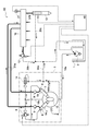
- FIG. 1 shows a schematic configuration of an accumulation type fuel injection device 50 according to an embodiment of the present invention.
- An accumulator fuel injector 50 shown in FIG. 1 is an accumulator fuel injector that injects fuel into a cylinder of an automatic transmission internal combustion engine mounted on a vehicle.
- the accumulator fuel injector 50 includes a fuel tank 1, a low-pressure pump 2, and the like.
- the high-pressure pump 5, the common rail 10, the fuel injection valve 13, and the like are provided as main elements.
- the low pressure pump 2 and the high pressure pump 5 are connected by a low pressure fuel passage 18a, and the high pressure pump 5 and the common rail 10, and the common rail 10 and the fuel injection valve 13 are connected by high pressure fuel passages 37a and 37b, respectively.
- fuel leak passages 30a to 30c for returning discharged fuel to the fuel tank 1 are connected to the high pressure pump 5, the common rail 10, the fuel injection valve 13, and the like.
- the “high pressure fuel system” means a region where the high pressure fuel spreads in the accumulator fuel injection device 50 and its constituent members.
- the high pressure fuel passages 37a, 37b, A common rail 10 and a fuel injection valve 13 are included.
- a flow control valve 8 for adjusting the flow rate of the low pressure fuel supplied to the high pressure pump 5 is provided.
- the overflow valve 14 is connected to the low pressure fuel passage 18a upstream of the flow control valve 8, and the pressure of the low pressure fuel is maintained at a predetermined value.
- the low pressure pump 2 pumps the low pressure fuel in the fuel tank 1 and pumps it, and supplies the low pressure fuel to the pressurizing chamber 5a of the high pressure pump 5 through the low pressure fuel passage 18a.
- a low-pressure pump 2 shown in FIG. 1 is an in-tank electric low-pressure pump provided in a fuel tank 1 in which low-pressure fuel is stored. The low-pressure pump 2 is driven by a voltage supplied from a battery and has a constant output and a constant flow rate. Pump fuel.
- the low-pressure pump 2 is not limited to the in-tank low-pressure pump, and may be provided outside the fuel tank 1. Further, the driving means of the low-pressure pump 2 may be a gear pump connected to the camshaft of the high-pressure pump 5 in addition to the electric pump.
- the flow rate control valve 8 provided in the low pressure fuel passage 18b for example, an electromagnetic proportional flow rate control valve whose passage area can be adjusted by controlling the energization amount by the control device 40 is used.
- the flow rate of the low-pressure fuel supplied to the pressurizing chamber 5a of the high-pressure pump 5 by the flow control valve 8 By adjusting the flow rate of the low-pressure fuel supplied to the pressurizing chamber 5a of the high-pressure pump 5 by the flow control valve 8, the pumping amount of the high-pressure fuel from the high-pressure pump 5 to the common rail 10 is adjusted to control the rail pressure. can do.
- the opening degree of the flow control valve 8 is maintained large in order to quickly increase the temperature of the high-pressure fuel system.
- the flow control valve 8 depends on the required rail pressure, the required injection amount of the internal combustion engine, and the like. And the flow rate of the low-pressure fuel supplied to the pressurizing chamber 5a is adjusted.
- the time difference from the output of the instruction until the rail pressure changes becomes larger.
- the overflow valve 14 connected to the low-pressure fuel flow path 18 a upstream from the flow control valve 8 is connected to a fuel leak passage 30 a communicating with the fuel tank 1.
- the overflow valve 14 used in the present embodiment is an overflow that opens when a difference between the front and rear pressures, that is, the pressure in the low-pressure fuel passage 18a and the pressure in the fuel leak passage 30a exceeds a predetermined value. A valve is used. Therefore, in a state where the low-pressure fuel is being pumped by the low-pressure pump 2, the pressure in the low-pressure fuel flow path 18a is maintained so as to be larger than the pressure in the fuel leak path 30a by a predetermined differential pressure.
- the high-pressure pump 5 is pumped by the low-pressure pump 2 and pressurizes the low-pressure fuel introduced into the pressurizing chamber 5a via the fuel intake valve 6 by the plunger 7, and the common rail 10 via the fuel discharge valve 9 and the high-pressure fuel passage 37a.
- High pressure fuel is pumped to
- the high-pressure pump 5 is driven by a cam 15 fixed to a camshaft connected to a drive shaft of an internal combustion engine via a gear. Further, in the high pressure pump 5 of the pressure accumulating fuel injection device 50 shown in FIG. 1, the two plungers 7 are pushed up by the cams 15, and the low pressure fuel is pressurized in the two pressurizing chambers 5a. High-pressure fuel is pumped from 5 a toward the common rail 10.
- the common rail 10 accumulates high-pressure fuel pumped from the high-pressure pump 5 and supplies high-pressure fuel to the plurality of fuel injection valves 13 via the high-pressure fuel passage 37b.
- a pressure sensor 21 and a pressure control valve 12 are attached to the common rail 10. Among these, the sensor value of the pressure sensor 21 is transmitted to the control device 40 and used for rail pressure control by the pressure control valve 12 provided in the common rail 10 or the flow rate control valve 8 provided in the high-pressure pump 5.
- the pressure control valve 12 for example, an electromagnetic proportional control valve whose passage area can be adjusted by controlling the energization amount is used.
- the opening of the pressure control valve 12 is adjusted according to the required rail pressure, the required injection amount of the internal combustion engine, and the like, and the high pressure discharged from the common rail 10 to the fuel leak passage 30b. The amount of fuel leakage is adjusted.
- the pressure control valve 12 is basically closed, and the rail pressure is larger than the target pressure by a predetermined value (hereinafter referred to as “valve opening threshold”) or more. Sometimes the pressure control valve 12 is opened.
- the fuel injection valve 13 connected to the common rail 10 injects high-pressure fuel by controlling the opening / closing timing of the injection hole by energization control in a state where high-pressure fuel is supplied.
- the fuel injection valve 13 for example, an electromagnetic control type fuel injection valve provided with a solenoid valve as a back pressure control unit, or an electrostrictive type fuel injection valve provided with a piezo element as a back pressure control unit is used.
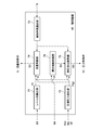
- FIG. 2 is a functional block diagram showing a portion related to rail pressure control in the configuration of the control device 40 that controls the accumulator fuel injection device 50 of the present embodiment.
- the control device 40 is configured around a microcomputer having a known configuration, and includes a rail pressure detection unit 71, a target pressure calculation unit 72, a control means selection unit 73, a flow rate control unit 74, and a high-pressure discharge.
- a control unit 75 and a valve opening number limiting unit 76 are provided. Specifically, each of these units is realized by executing a program by a microcomputer.
- the control device 40 includes a RAM (Random Access Memory) (not shown), and stores calculation results and detection results at each unit.
- RAM Random Access Memory
- the rail pressure detection unit 71 reads the sensor value S1 of the pressure sensor 21 provided on the common rail 10 at regular time intervals and calculates the rail pressure Pr based on the sensor value S1.
- the target pressure calculation unit 72 calculates the target pressure Ptgt of the common rail based on the accelerator operation amount Acc, the internal combustion engine speed Ne, the fuel injection amount instruction value Qf, and the like.
- the calculated rail pressure Pr and target pressure Ptgt are transmitted to the flow rate control unit 74 and the high pressure discharge control unit 75 and used for rail pressure control.
- the calculated rail pressure Pr is also transmitted to the valve opening number limiting unit 76.
- the control means selection unit 73 determines whether the flow control valve 8 or the pressure control valve 12 is used for feedback control of the rail pressure Pr using the rail pressure Pr and the target pressure Ptgt.
- the rail pressure Pr is adjusted by adjusting the supply amount of high-pressure fuel to the common rail 10, whereas the rail using the pressure control valve 12 is controlled.
- the rail pressure Pr is adjusted by adjusting the discharge amount of the high-pressure fuel from the common rail 10.
- the rail pressure control using the pressure control valve 12 when the temperature Tf detected by the temperature sensor provided in the high pressure fuel system does not reach the predetermined value, the rail pressure control using the pressure control valve 12 is performed. Otherwise, rail pressure control using the flow control valve 8 is selected. That is, rail pressure control using the pressure control valve 12 is selected in situations where it is desired to quickly increase the temperature of the high-pressure fuel system, such as immediately after the start of the internal combustion engine, and rail pressure control using the flow control valve 8 during normal operation. Control is selected.
- the control means selection unit 73 transmits the selection result to the flow rate control unit 74 and the high pressure discharge control unit 75.
- the flow rate control unit 74 mainly uses the rail pressure Pr and the target pressure Ptgt transmitted from the rail pressure detection unit 71 and the target pressure calculation unit 72 in the normal operation state of the internal combustion engine. Is adjusted to control the rail pressure Pr by adjusting the flow rate of the low-pressure fuel. On the other hand, the flow rate control unit 74 performs control so that the flow rate control valve 8 is maintained at a predetermined opening degree when the internal combustion engine is started.
- the rail pressure feedback control is performed by the pressure control valve 12 at the time of starting the internal combustion engine, etc.
- the high pressure fuel exceeding the maximum fuel injection amount assumed in all operating states is common rail 10.
- the opening degree of the flow control valve 8 is set so as to be supplied.
- the flow control unit 74 determines the movement amount of the piston of the flow control valve 8 according to the deviation ⁇ P between the rail pressure Pr and the target pressure Ptgt, and the actuator of the flow control valve 8 A control signal S2 is output to (not shown). As a result, the supply amount of the low pressure fuel to the high pressure pump 5 is adjusted, and the flow rate of the high pressure fuel supplied to the common rail 10 is changed.
- the high pressure discharge control unit 75 mainly opens the pressure control valve 12 using the rail pressure Pr and the target pressure Ptgt transmitted from the rail pressure detection unit 71 and the target pressure calculation unit 72 at the time of starting the internal combustion engine.
- the rail pressure Pr is feedback controlled by adjusting the degree.
- the high-pressure exhaust control unit 75 basically performs control to fully close the pressure control valve 12 in the normal operation state of the internal combustion engine.
- the set value Ppcv of the target pressure is relatively increased, and in order to decrease the opening degree, the set value Ppcv of the target pressure is relatively decreased.
- the high pressure discharge control unit 75 determines the amount of movement of the piston of the pressure control valve 12 according to the deviation ⁇ P between the rail pressure Pr and the target pressure Ptgt, and pressure control A control signal S3 is output to an actuator (not shown) of the valve 12. As a result, the flow rate of the high pressure fuel discharged from the common rail 10 is changed.
- the high pressure discharge control unit 75 basically closes the pressure control valve 12 completely, but the rail pressure Pr becomes greater than the target pressure Ptgt by a predetermined valve opening threshold ⁇ P0 or more.
- the control signal S3 for opening the valve is output to the pressure control valve 12.
- part of the high-pressure fuel is discharged from the common rail 10 in accordance with the opening degree or valve opening time of the pressure control valve 12, and the rail pressure Pr is reduced.
- the number Nv of opening of the pressure control valve 12 is limited. Therefore, the rail pressure Pr exceeds the target pressure Ptgt several times after the fuel injection cut control. Even in such a case, the number of outputs of the control signal S3 for instructing opening of the pressure control valve 12 is limited to the set number of opening times Nv0.
- valve opening number limiting unit 76 When the valve opening number limiting unit 76 receives a signal S4 indicating that a fuel injection cut control execution instruction for temporarily reducing the fuel injection amount by the fuel injection valve 13 is transmitted to a fuel injection control unit (not shown). Then, the instruction signal S5 is transmitted to the high pressure discharge control unit 75 so as to limit the number of opening times Nv of the pressure control valve 12.
- the valve opening number limiting unit 76 of the control device 40 of the present embodiment is the pressure control valve 12 only when the rail pressure Pr transmitted from the rail pressure detection unit 71 during rail pressure fuel injection cut control is equal to or greater than a predetermined threshold value P0. Is set so as to limit the number of opening times Nv. This is because the hunting phenomenon is prevented only when the rail pressure Pr is estimated to exceed the allowable pressure of the high-pressure fuel system when the rail pressure Pr hunting phenomenon occurs. When Pr hunting occurs, the rail pressure Pr is set to a value estimated to exceed the allowable pressure of the high-pressure fuel system.
- the instruction value Qf of the fuel injection amount is temporarily reduced in response to a torque reduction request at the time of gear shift of the internal combustion engine.
- the valve opening number limiting unit 76 of the present embodiment is a high pressure so that the pressure control valve 12 is opened only once when the fuel injection cut control is executed and the rail pressure Pr is equal to or higher than the threshold value P0.
- An instruction signal S5 is transmitted to the discharge controller 75.
- the valve opening number limiting unit 76 is configured to set an opening when the valve is opened only once and to instruct the high pressure discharge control unit 75.
- the number of opening times Nv0 may be set twice or more, but in order to reduce the damage of the high-pressure fuel system due to the increase / decrease in the rail pressure Pr, it should be set to at most three times. It is preferable.
- the opening degree at the time of opening the valve is calculated based on, for example, the stroke position of the plunger that pressurizes the fuel with the high-pressure pump 5 when the fuel injection cut control is executed, or the amount of decrease in the fuel injection amount.
- These elements for determining the opening degree that is, the time until the flow rate of the high-pressure fuel actually supplied to the common rail 10 decreases after the instruction from the flow rate control unit 74 to the flow rate control valve 8 is output. It has an influence and is not limited to the example described above.
- the processing capability of the control device 40 can also be an element.
- the opening degree of the control valve 12, that is, the set value Ppcv of the target value of the rail pressure used for the control instruction to the pressure control valve 12 is increased.
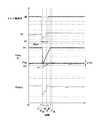
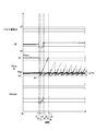
- FIG. 3 shows the fuel injection amount instruction value Qf, the pressure control valve 12 set value Ppcv, when the control device 40 of the present embodiment performs control to limit the number of opening times Nv of the pressure control valve 12.
- 6 is a timing chart showing changes in an instruction flow rate Vmeun to the flow control valve 8 and a rail pressure Pr.
- the set value Ppcv of the pressure control valve 12 is set to P1, which is higher than the target value Ptgt of the rail pressure. In this state, the pressure control valve 12 is closed.
- the fuel injection amount instruction value Qf changes smoothly, and the instruction flow rate Vmeun to the flow control valve 8 changes gently according to the change of the fuel injection amount instruction value Qf. To do. For this reason, the rail pressure Pr is maintained while being kept substantially at the rail pressure target value Ptgt.
- This rail pressure target value Ptgt is larger than the threshold value P0, and the rail pressure Pr is also equal to or higher than the threshold value P0.
- the fuel injection amount command value Qf and the command flow rate Vmeun to the flow control valve 8 are temporarily reduced.
- the amount of high-pressure fuel discharged from the common rail 10 rapidly decreases due to a decrease in high-pressure fuel injected from the fuel injection valve 13, while a decrease to the flow control valve 8 provided on the inlet side of the high-pressure pump 5.
- the rail pressure Pr starts to increase for a while after the time t1.
- the set value Ppcv of the pressure control valve 12 is reduced to the rail pressure target value Ptgt at the time t2 when the deviation ⁇ P between the rail pressure Pr and the rail pressure target value Ptgt becomes greater than the valve opening threshold ⁇ P0.
- the rail pressure Pr starts to decrease.
- the torque reduction request is turned off at time t6, the rail pressure Pr exceeds the rail pressure target value Ptgt at time t7, and the difference ⁇ P between the rail pressure Pr and the rail pressure target value Ptgt at time t8. Is equal to or greater than the valve opening threshold value ⁇ P0, but the set value Ppcv of the pressure control valve 12 is reduced because the number of opening times Nv0 of the pressure control valve 12 when the fuel injection cut control is executed is limited to one. There is nothing. However, the command value Qf of the fuel injection amount after the torque reduction request is turned off gradually changes, and the command flow rate Vmeun of the flow control valve is adjusted accordingly. The hunting phenomenon does not occur, and the rail pressure Pr is substantially maintained at the target value Ptgt of the rail pressure.
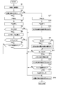
- step S1 a rail pressure control method performed by the control device 40 of the present embodiment shown in FIG. 2 will be described based on the control flow of FIG. 4.
- step S1 it is determined which of the flow control valve 8 or the pressure control valve 12 is used to perform the rail pressure control.
- the fuel temperature Tf calculated based on the sensor value of the fuel temperature sensor provided in any part of the accumulator fuel injection device 50 is compared with a predetermined threshold value Tf0, and the fuel temperature Tf is When the fuel temperature Tf is lower than the threshold value Tf0, rail pressure control is performed using the pressure control valve 12 in order to quickly increase the fuel temperature Tf.
- the flow control valve 8 is used. Rail pressure control is performed.
- the selection method of the control means is not limited to the above example.
- step S2 it is determined in step S2 whether or not it is in the rail pressure control mode by the flow control valve 8, and in the case of the rail pressure control mode by the flow control valve 8, the process proceeds to step S3.
- step S17 the process proceeds to step S17.
- the rail pressure Pr is detected based on the sensor value of the pressure sensor 21 provided on the common rail 10
- the target of the common rail 10 is detected in step S18.
- the pressure Ptgt is calculated, and in step S19, the control signal S3 of the pressure control valve 12 is output based on the deviation ⁇ P between the target pressure Ptgt and the rail pressure Pr, and this routine ends.
- step S3 in which the rail pressure control mode by the flow control valve 8 is selected and advanced, the rail pressure Pr is detected based on the sensor value of the pressure sensor 21 provided on the common rail 10, and the target of the common rail 10 is further detected in step S4. Calculate the pressure Ptgt.
- step S5 it is determined whether or not the rail pressure Pr is equal to or greater than a predetermined threshold value P0. If the rail pressure Pr is less than the threshold value P0, the process proceeds to step S16, while the rail pressure Pr is equal to or greater than the threshold value P0. If so, the process proceeds to step S6.
- step S6 a deviation ⁇ P between the target pressure Ptgt and the rail pressure Pr is obtained, and then in step S7, it is determined whether or not the obtained deviation ⁇ P is equal to or greater than the valve opening threshold value ⁇ P0. If the deviation ⁇ P is less than the valve opening threshold ⁇ P0, the process proceeds to step S16 as it is, whereas if the deviation ⁇ P is greater than or equal to the valve opening threshold ⁇ P0, the process proceeds to step S8.
- step S8 it is determined whether the torque reduction request is on. If the torque reduction request is off, the process proceeds directly to step S12. If the torque reduction request is on, the process proceeds to step S9, and whether or not the number Nv of opening of the pressure control valve 12 stored in the RAM is 0 is determined. Determined. If the valve opening number Nv is not zero, the process proceeds to step S11 as it is. On the other hand, if the valve opening number Nv is zero, an instruction signal S5 for limiting the valve opening number Nv of the pressure control valve 12 is output in step S10. Proceed to step S11.
- step S11 it is determined whether or not the number of opening times Nv of the pressure control valve 12 stored in the RAM is less than the set value Nv0.
- the process proceeds to step S16 as it is, while when the valve opening number Nv is less than the set value Nv0, the process proceeds to step S12 and the opening degree of the pressure control valve 12 is determined. Then, the process proceeds to step S13, and after the control signal S3 for instructing opening of the valve is output to the pressure control valve 12, the process proceeds to step S14.
- step S14 it is determined whether or not the torque reduction request is off. If the torque reduction request is on, the process proceeds directly to step S16. If the torque reduction request is off, the opening stored in the RAM in step S15. After resetting the valve number Nv, the process proceeds to step S16. In step S16, the control signal S2 of the flow control valve 8 is output based on the deviation ⁇ P obtained in step S6, and this routine is terminated.
- the torque reduction request is independent of the accelerator operation amount while the rail pressure control is being performed by adjusting the flow rate of the low-pressure fuel by the flow rate control valve 8.
- the rail pressure is repeatedly increased and decreased to prevent the rail pressure hunting phenomenon from occurring.
- the number of overshoots in which the rail pressure exceeds the allowable pressure of the high-pressure fuel system is reduced, so that the possibility of damage to the high-pressure fuel system is also reduced.
- the rail pressure hunting phenomenon is controlled by limiting the number of times the pressure control valve is opened, the rail pressure hunting phenomenon can be reliably ensured even if there are variations in processing accuracy during manufacturing of the pressure control valve. Is prevented.
Landscapes
- Engineering & Computer Science (AREA)
- Chemical & Material Sciences (AREA)
- Combustion & Propulsion (AREA)
- Mechanical Engineering (AREA)
- General Engineering & Computer Science (AREA)
- Fuel-Injection Apparatus (AREA)
- Electrical Control Of Air Or Fuel Supplied To Internal-Combustion Engine (AREA)
Abstract
燃料噴射カット制御に起因するレール圧のハンチング現象を防止できるコモンレール圧力の制御装置及び制御方法並びに蓄圧式燃料噴射装置を提供する。 燃料タンク内の低圧燃料を低圧ポンプで圧送するとともに、高圧ポンプに供給される低圧燃料の流量を調節しながら高圧ポンプで低圧燃料を加圧して複数の燃料噴射弁が接続されたコモンレールに高圧燃料を圧送する蓄圧式燃料噴射装置におけるコモンレール内の圧力を制御するためのコモンレール圧力の制御装置において、コモンレール内の圧力が目標圧力よりも所定値以上大きくなったときに、コモンレール内の高圧燃料を排出するための圧力制御弁を開弁する制御が行われるように構成されており、燃料噴射弁からの燃料噴射量が一時的に減少させられる制御によってコモンレール内の圧力が目標圧力よりも所定値以上大きくなったときの圧力制御弁の開弁回数が制限されるようにした。
Description
本発明は、コモンレール圧力の制御装置及び制御方法並びに蓄圧式燃料噴射装置に関し、高圧ポンプへの低圧燃料の圧送量とコモンレールからの高圧燃料の排出量とを調節することでコモンレール内の圧力を制御する形式のコモンレール圧力の制御装置及び制御方法並びに蓄圧式燃料噴射装置に関する。
従来、ディーゼルエンジンをはじめとする内燃機関に燃料を噴射する装置として、複数の燃料噴射弁が接続されるとともに高圧燃料が蓄積されるコモンレールを備え、高圧燃料が各燃料噴射弁に供給された状態で燃料噴射弁の通電制御を行うことによって、燃料の緻密な噴射制御を可能にした蓄圧式燃料噴射装置が用いられている。
このような蓄圧式燃料噴射装置は、低圧ポンプと、高圧ポンプと、コモンレールと、燃料噴射弁とを主たる要素として備えており、燃料タンク内の燃料が低圧ポンプによって高圧ポンプに圧送されるとともに高圧ポンプによって加圧されてコモンレールに圧送され、各燃料噴射弁に高圧燃料が供給される。この状態で燃料噴射弁への通電のオンオフによって燃料噴射弁の開弁時期及び開弁時間が制御されることで、内燃機関への様々な燃料噴射パターンが実現可能となっている。
この蓄圧式燃料噴射装置では、高圧ポンプの加圧室に供給する低圧燃料の流量を調節したり、あるいは、コモンレールに圧送された高圧燃料の一部を低圧系に戻したり、さらには、これらの制御を併用したりすることによって、コモンレール内の圧力(以下「レール圧」と称する。)を調節している(例えば、特許文献1参照)。
例えば、内燃機関の始動直後等の燃料噴射装置の温度が低い場合には、低圧燃料の流量を調節しないで大量の高圧燃料をコモンレールに圧送しつつ、レール圧の目標値に応じてコモンレールに接続された圧力制御弁を開閉して高圧燃料の一部を燃料タンクに戻す制御が行われる。このような圧力制御弁によるレール圧制御では、レール圧を直接調節できるために応答性が良いとともに、大量の高圧燃料が圧送されることによって燃料温度が上昇するために高圧燃料系の温度を速やかに適温まで上昇させることができる一方、燃料タンクに戻される高圧燃料が比較的多くなるために燃料の利用効率が低くなる。
一方、燃料噴射装置の温度が上昇した後は、圧力制御弁を閉じ、加圧室に送る低圧燃料の流量を制御する流量制御弁の開度をレール圧の目標値に応じて調節して、必要な量の高圧燃料をコモンレールに圧送する制御が行われる。このような流量制御弁によるレール圧制御では、必要な量の高圧燃料のみがコモンレールに圧送されるため燃料の利用効率が向上する一方、制御装置によって流量制御弁の開度の指示が出力されてから実際にレール圧が変動するまでに時間差が生じることから応答性が低下しやすくなる。
ところで、蓄圧式燃料噴射装置において、レール圧が目標圧力よりも所定値以上大きくなった時にはレール圧が速やかに目標圧力に近づくように制御される必要があるが、流量制御弁によってレール圧が制御されている場合には、流量制御弁の開度の指示が出力されてから実際にレール圧が変動するまでに時間差が生じやすい。そのため、流量制御弁によってレール圧が制御されている場合にレール圧が目標圧力よりも所定値以上大きくなったときには、圧力制御弁を開弁してレール圧を低下させる制御が行われる場合がある。
特に、流量制御弁によってレール圧が制御された状態において、アクセルが踏まれたままで一時的に燃料噴射量を減少させる制御(以下「燃料噴射カット制御」と称する。)が実行された場合に、燃料噴射量が減少したにもかかわらずコモンレールへの高圧燃料の圧送量の減少が追従できずにレール圧が高圧燃料系の許容圧力を超えるおそれがある。燃料噴射カット制御は、例えば、オートマチックトランスミッション仕様車のギヤシフトアップ時に、トランスミッションのトルクの低減を図ることを目的として行われる。
このような燃料噴射カット制御時に圧力制御弁の開弁制御が行われると一旦レール圧が低下することになるが、その後に、圧力制御弁が徐々に閉じられるとともに流量制御弁の開度が増大されると、今度はレール圧が上昇に転じる。さらに、この圧力制御弁及び流量制御弁の開閉と前後して、燃料噴射カット制御も終了することから、レール圧は徐々に上昇し続けることになる。
そして、以降は、レール圧上昇時の圧力制御弁の開弁及び流量制御弁の開度の絞りによるレール圧の低下と、レール圧低下時の圧力制御弁の閉弁及び流量制御弁の開度の増大によるレール圧の上昇とが繰り返されて、レール圧のハンチング現象が発生する。このようなレール圧のハンチング現象が生じるのは、従来の蓄圧式燃料噴射装置では、レール圧が目標レール圧よりも所定値以上高くなったときには必ず圧力制御弁が開弁されるように設定されていることによる。このレール圧のハンチング現象が生じると、燃料噴射量の制御が困難になるとともに、高圧燃料系内の圧力脈動によって高圧燃料系の耐久性が低下するおそれがある。
図5は、従来の燃料噴射カット制御実行時におけるレール圧のハンチング現象を示すタイミングチャートであり、燃料噴射量の指示値Qf、圧力制御弁のセット値Ppcv、流量制御弁への指示流量Vmeun、及びレール圧Prの変化を示している。
このチャートにおいて、オートマチックトランスミッションのトルクを減少させる要求(以下、「トルク減要求」と称する。)がオフのt0からt1の期間中、圧力制御弁のセット値Ppcvはレール圧の目標値Ptgtよりも高いP1にセットされている。この状態では、圧力制御弁は閉じられた状態にある。また、このt0からt1の期間中、燃料噴射量の指示値Qfはなだらかに推移しており、流量制御弁への指示流量Vmeunは燃料噴射量の指示値Qfの推移に応じてなだらかに推移する。そのため、レール圧Prはほぼレール圧の目標値Ptgtで保たれたまま推移している。
このチャートにおいて、オートマチックトランスミッションのトルクを減少させる要求(以下、「トルク減要求」と称する。)がオフのt0からt1の期間中、圧力制御弁のセット値Ppcvはレール圧の目標値Ptgtよりも高いP1にセットされている。この状態では、圧力制御弁は閉じられた状態にある。また、このt0からt1の期間中、燃料噴射量の指示値Qfはなだらかに推移しており、流量制御弁への指示流量Vmeunは燃料噴射量の指示値Qfの推移に応じてなだらかに推移する。そのため、レール圧Prはほぼレール圧の目標値Ptgtで保たれたまま推移している。
ここで、t1の時点でオートマチックトランスミッションによるギアの変速を行うためにトルク減要求がオンになると、燃料噴射量の指示値Qf及び流量制御弁への指示流量Vmeunが一時的に減少させられる。このとき、燃料噴射弁から噴射される高圧燃料の減少によってコモンレールから外部に出される高圧燃料の量は速やかに減る一方、高圧ポンプの入口側に設けられた流量制御弁への減少指示の出力のタイミングと、実際にコモンレールに圧送される高圧燃料の流量が減少するまでのタイミングとに時間差が生じることになる。
そのため、t1の時点以降しばらくの間はレール圧Prが上昇に転じる。そして、レール圧Prとレール圧の目標値Ptgtとの偏差ΔPが所定値ΔP0以上大きくなるt2の時点で、圧力制御弁のセット値Ppcvがレール圧の目標値Ptgtまで減少させられる結果、レール圧Prは減少傾向に転じる。
その後、t3の時点で、レール圧Prとレール圧の目標値Ptgtとの偏差ΔPが所定値ΔP0未満になると圧力制御弁のセット値Ppcvは徐々にP1に戻されるが、レール圧Prがさらに低下してレール圧の目標値Ptgtを下回ると、t4の時点で、今度は流量制御弁への指示流量Vmeunが増加させられる。そうすると、レール圧Prが再び上昇に転じるとともに、その後t5の時点で、オートマチックトランスミッションによるギアの変速が完了し燃料噴射量の指示値Qfの減少が解除されることで一旦レール圧Prの上昇が止まるため、流量制御弁への指示流量Vmeunがさらに増加させられ、再びレール圧Prが上昇する。そして、レール圧Prが再び上昇傾向に転じると流量制御弁への指示流量Vmeunが徐々に小さくされる。
その後、t6の時点でトルク減要求がオフにされ、その後レール圧Prがレール圧の目標値Ptgtを上回り、さらにt7の時点でレール圧Prとレール圧の目標値Ptgtとの偏差ΔPが所定値ΔP0以上になると、再び圧力制御弁のセット値Ppcvがレール圧の目標値Ptgtまで減少させられる。その結果、t8の時点でレール圧Prが減少傾向に転じるため、t9の時点でレール圧Prがレール圧の目標値Ptgtを下回ると、今度は再び流量制御弁への指示流量Vmeunが増加させられてレール圧Prが上昇傾向に転じる。
その後は、レール圧Prとレール圧の目標値Ptgtとの偏差ΔPが所定値ΔP0以上になるたびに圧力制御弁のセット値Ppcvが減少させられるため、圧力制御弁及び流量制御弁の制御によってレール圧Prの増減が繰り返されてハンチング現象が発生している。
このような理由で発生するレール圧のハンチング現象を抑えるために、圧力制御弁開弁時の開度や開弁時間を適切に設定することも考えられるが、圧力制御弁は製造時の加工精度等のばらつきによる個体差があるため設定値が個々に変わってしまう。そのため、ある圧力制御弁に合わせて開弁時の開度や開弁時間を設定したとしても、すべてのコモンレールの圧力のハンチング現象が防止されにくい。
そこで、本発明の発明者は鋭意努力し、高圧ポンプに圧送する低圧燃料の流量を調節することによるレール圧制御中での燃料噴射カット制御の実行時に、コモンレールに接続された圧力制御弁の開弁回数を制限することにより、上述した問題が解決されることを見出し、本発明を完成させたものである。すなわち、本発明は、燃料噴射カット制御に起因するレール圧のハンチング現象を防止できるコモンレール圧力の制御装置及び制御方法並びに蓄圧式燃料噴射装置を提供することを目的とする。
本発明によれば、燃料タンク内の低圧燃料を低圧ポンプで圧送するとともに、高圧ポンプで低圧燃料を加圧して複数の燃料噴射弁が接続されたコモンレールに高圧燃料を圧送し、燃料噴射弁から内燃機関の気筒内に高圧燃料を噴射する蓄圧式燃料噴射装置におけるコモンレール内の圧力を制御するためのコモンレール圧力の制御装置において、コモンレールの目標圧力に応じて高圧ポンプに圧送する低圧燃料の流量を調節している間に、コモンレール内の圧力が目標圧力よりも所定値以上大きくなったときにはコモンレール内の高圧燃料を排出するための圧力制御弁を開弁する制御が行われるように構成されており、燃料噴射弁からの燃料噴射量が一時的に減少させられる制御によってコモンレール内の圧力が目標圧力よりも所定値以上大きくなったときの圧力制御弁の開弁回数が制限されるようにしたことを特徴とするコモンレール圧力の制御装置が提供され、上述した問題を解決することができる。
また、本発明のコモンレール圧力の制御装置を構成するにあたり、圧力制御弁の開弁回数が一回に制限されるとともに、一回の開弁時の開度が、燃料噴射量が一時的に減少させられたときの高圧ポンプのプランジャの位置又は燃料噴射量の減少量のうちの少なくとも一つに応じて設定されることが好ましい。
また、本発明のコモンレール圧力の制御装置において、圧力制御弁の開弁回数の制限は、燃料噴射量が一時的に減少させられるときのコモンレール内の圧力が所定の閾値以上のときに行われることが好ましい。
また、本発明のコモンレール圧力の制御装置において、燃料噴射量が一時的に減少させられる制御は、前記内燃機関が搭載された車両のギア変速時におけるオートマチックトランスミッションのトルクを減少させるために行われる制御であることが好ましい。
また、本発明のコモンレール圧力の制御装置が、コモンレール内の圧力を検出するレール圧検出部と、目標圧力に応じて高圧ポンプに供給される低圧燃料の流量を調節する流量制御部と、コモンレール内の圧力が目標圧力よりも所定値以上大きくなったときに圧力制御弁を開弁させる高圧排出制御部と、燃料噴射弁からの燃料噴射量が一時的に減少させられる制御の実行時に高圧排出制御部による圧力制御弁の開弁回数を制限する開弁回数制限部と、を備えることが好ましい。
また、本発明の別の態様は、燃料タンク内の低圧燃料を低圧ポンプで圧送するとともに、高圧ポンプで低圧燃料を加圧して複数の燃料噴射弁が接続されたコモンレールに高圧燃料を圧送し、燃料噴射弁から内燃機関の気筒内に高圧燃料を噴射する蓄圧式燃料噴射装置におけるコモンレール内の圧力を制御するためのコモンレール圧力の制御方法において、コモンレールの目標圧力に応じて高圧ポンプに圧送する低圧燃料の流量を調節している間に、コモンレール内の圧力が目標圧力よりも所定値以上大きくなったときにはコモンレール内の高圧燃料を排出するための圧力制御弁を開弁することでコモンレール内の圧力が低下させられ、燃料噴射弁からの燃料噴射量が一時的に減少させられる制御によってコモンレール内の圧力が目標圧力よりも所定値以上大きくなったときの圧力制御弁の開弁回数を制限することを特徴とするコモンレール圧力の制御方法である。
また、本発明のさらに別の態様は、燃料タンク内の低圧燃料を低圧ポンプで圧送するとともに、高圧ポンプで低圧燃料を加圧して複数の燃料噴射弁が接続されたコモンレールに高圧燃料を圧送し、燃料噴射弁から内燃機関の気筒内に高圧燃料を噴射する蓄圧式燃料噴射装置において、高圧ポンプに圧送される低圧燃料の流量を制御するための流量制御弁と、コモンレールに設けられコモンレール内の高圧燃料を排出するための圧力制御弁と、コモンレールの目標圧力に応じて流量制御弁を制御することでコモンレール内の圧力を制御可能であるとともにこの制御中にコモンレール内の圧力が目標圧力よりも所定値以上大きくなったときには圧力制御弁を開弁するレール圧制御装置と、を備え、レール圧制御装置は、燃料噴射弁からの燃料噴射量が一時的に減少させられる制御によってコモンレール内の圧力が目標圧力よりも所定値以上大きくなったときの圧力制御弁の開弁回数を制限可能であることを特徴とする蓄圧式燃料噴射装置である。
本発明のコモンレール圧力の制御装置及び制御方法によれば、燃料噴射カット制御時にレール圧が目標圧力よりも所定値以上大きくなったときの圧力制御弁の開弁回数が制限される。そのため、高圧ポンプに圧送する低圧燃料の流量が変化してから、この低圧燃料の流量の変化に伴いコモンレールに圧送される高圧燃料の流量が変化しレール圧が変化するまでの時間差によって、レール圧の上昇及び下降が繰り返されてレール圧のハンチング現象を生じることが抑えられる。また、圧力制御弁の開弁回数を制限したとしても、燃料噴射カット制御の終了後には燃料噴射量が安定しレール圧が安定しはじめることから、圧力制御弁を開弁しなくても、高圧ポンプに圧送する低圧燃料の流量の制御によってレール圧が安定的に維持される。
また、本発明の蓄圧式燃料噴射装置によれば、燃料噴射カット制御時にレール圧が目標圧力よりも所定値以上大きくなったときの圧力制御弁の開弁回数を制限するコモンレール圧力の制御装置を備えているため、燃料噴射カット制御によるレール圧のハンチング現象が抑えられ、その後の燃料噴射量の制御が精度よく行われるとともに、圧力の振幅による高圧燃料系の耐久性の低下が防止される。
以下、図面を参照して、本発明のコモンレール圧力の制御装置及び制御方法並びに蓄圧式燃料噴射装置に関する実施の形態について具体的に説明する。ただし、かかる実施の形態は本発明の一態様を示すものであり、この発明を限定するものではなく、本発明の範囲内で任意に変更することが可能である。なお、それぞれの図中、同じ符号を付してあるものは同一の部材を示しており、適宜説明が省略されている。
1.蓄圧式燃料噴射装置の基本的構成
図1は、本発明の実施の形態にかかる蓄圧式燃料噴射装置50の概略構成を示している。
この図1に示す蓄圧式燃料噴射装置50は、車両に搭載されたオートマチックトランスミッション式の内燃機関の気筒内に燃料を噴射する蓄圧式燃料噴射装置であって、燃料タンク1と、低圧ポンプ2と、高圧ポンプ5と、コモンレール10と、燃料噴射弁13等を主たる要素として備えている。
図1は、本発明の実施の形態にかかる蓄圧式燃料噴射装置50の概略構成を示している。
この図1に示す蓄圧式燃料噴射装置50は、車両に搭載されたオートマチックトランスミッション式の内燃機関の気筒内に燃料を噴射する蓄圧式燃料噴射装置であって、燃料タンク1と、低圧ポンプ2と、高圧ポンプ5と、コモンレール10と、燃料噴射弁13等を主たる要素として備えている。
低圧ポンプ2と高圧ポンプ5は低圧燃料通路18aで接続され、高圧ポンプ5とコモンレール10、及びコモンレール10と燃料噴射弁13はそれぞれ高圧燃料通路37a、37bで接続されている。また、高圧ポンプ5やコモンレール10、燃料噴射弁13等には、排出される燃料を燃料タンク1に戻すための燃料リーク通路30a~30cが接続されている。
なお、本明細書において、「高圧燃料系」とは蓄圧式燃料噴射装置50のうちの高圧燃料が行き渡る領域及びその構成部材を意味し、本実施形態の例では、高圧燃料通路37a、37b、コモンレール10、燃料噴射弁13が含まれる。
低圧燃料通路18aの途中には、高圧ポンプ5に供給される低圧燃料の流量を調節するための流量制御弁8が備えられている。また、流量制御弁8よりも上流側の低圧燃料通路18aにはオーバーフローバルブ14が接続され、低圧燃料の圧力が所定の値に維持される。
低圧ポンプ2は、燃料タンク1内の低圧燃料を汲み上げて圧送し、低圧燃料通路18aを介して高圧ポンプ5の加圧室5aに低圧燃料を供給する。図1に示される低圧ポンプ2は、低圧燃料が貯蔵された燃料タンク1内に備えられたインタンクの電動低圧ポンプであって、バッテリーから供給される電圧によって駆動され一定出力で定流量の低圧燃料を圧送する。
ただし、低圧ポンプ2はインタンクの低圧ポンプに限られるものではなく、燃料タンク1の外部に設けられるものであってもよい。また、低圧ポンプ2の駆動手段についても電動式のポンプ以外に、高圧ポンプ5のカムシャフトに連結されたギアポンプであってもよい。
低圧燃料通路18bに備えられた流量制御弁8は、例えば、制御装置40によって通電量が制御されることで通路面積が調節可能な電磁比例式の流量制御弁が用いられる。この流量制御弁8によって高圧ポンプ5の加圧室5aに供給される低圧燃料の流量が調節されることで、高圧ポンプ5からコモンレール10への高圧燃料の圧送量が調節され、レール圧を制御することができる。
例えば、内燃機関の始動直後等においては、高圧燃料系の温度を速やかに上昇させるために流量制御弁8の開度が大きく維持される。一方、内燃機関の通常運転状態においては、蓄圧式燃料噴射装置50の負荷に対する燃料の利用効率を高くするために、要求されるレール圧及び内燃機関の要求噴射量等に応じて流量制御弁8の開度が調節され、加圧室5aに供給される低圧燃料の流量が調節される。ただし、コモンレール10に設けられた圧力制御弁12によるレール圧制御に比べて、指示の出力からレール圧が変化するまでの時間差が大きくなる。
流量制御弁8よりも上流側の低圧燃料流路18aに接続されたオーバーフローバルブ14は燃料タンク1に通じる燃料リーク通路30aに接続されている。本実施形態で用いられるオーバーフローバルブ14は、前後の差圧、すなわち、低圧燃料通路18a内の圧力と、燃料リーク通路30a内の圧力との差が所定値を越えたときに開弁されるオーバーフローバルブが用いられている。したがって、低圧ポンプ2によって低圧燃料が圧送されている状態においては、低圧燃料流路18a内の圧力が、燃料リーク通路30a内の圧力に対して所定の差圧分大きくなるように維持される。
高圧ポンプ5は、低圧ポンプ2によって圧送され、燃料吸入弁6を介して加圧室5aに導入された低圧燃料をプランジャ7によって加圧し、燃料吐出弁9及び高圧燃料通路37aを介してコモンレール10に高圧燃料を圧送する。この高圧ポンプ5は、内燃機関のドライブシャフトにギアを介して連結されたカムシャフトに固定されているカム15によって駆動される。また、図1に示す蓄圧式燃料噴射装置50の高圧ポンプ5は、二本のプランジャ7がカム15によって押し上げられ、二つの加圧室5a内で低圧燃料が加圧されて、各加圧室5aからコモンレール10に向けて高圧燃料が圧送される。
コモンレール10は、高圧ポンプ5から圧送されてくる高圧燃料を蓄積するとともに、高圧燃料通路37bを介して複数の燃料噴射弁13に対して高圧燃料を供給する。このコモンレール10には圧力センサ21及び圧力制御弁12が取り付けられている。このうち圧力センサ21のセンサ値は、制御装置40に伝達されて、コモンレール10に備えられた圧力制御弁12又は高圧ポンプ5に備えられた流量制御弁8によるレール圧制御に用いられる。
圧力制御弁12としては、例えば、通電量が制御されることによって通路面積が調節可能な電磁比例制御弁が用いられる。例えば、内燃機関の始動直後等においては、要求されるレール圧及び内燃機関の要求噴射量等に応じて圧力制御弁12の開度が調節され、コモンレール10から燃料リーク通路30bに排出される高圧燃料のリーク量が調節される。一方、エンジンの通常運転状態においては、圧力制御弁12は基本的に閉じられた状態であり、レール圧が目標圧力よりも所定値(以下、「開弁閾値」と称する。)以上大きくなった時に圧力制御弁12が開弁される。
コモンレール10に接続された燃料噴射弁13は、高圧燃料が供給された状態で、通電制御によって噴射孔の開閉の時期が制御されることで、高圧燃料の噴射を行う。燃料噴射弁13は、例えば、背圧制御部としてソレノイドバルブが備えられた電磁制御型の燃料噴射弁や、背圧制御部としてピエゾ素子が備えられた電歪型の燃料噴射弁が用いられる。
2.制御装置(コモンレール圧力の制御装置)
図2は、本実施形態の蓄圧式燃料噴射装置50を制御する制御装置40の構成のうち、レール圧制御に関する部分を機能的なブロックで表した図を示している。
この制御装置40は、公知の構成からなるマイクロコンピュータを中心に構成されており、レール圧検出部71と、目標圧力演算部72と、制御手段選択部73と、流量制御部74と、高圧排出制御部75と、開弁回数制限部76とを備えている。これらの各部は、具体的にはマイクロコンピュータによるプログラムの実行によって実現される。また、制御装置40には、図示しないRAM(Random Access Memory)が備えられ、各部での演算結果や検出結果が記憶される。
図2は、本実施形態の蓄圧式燃料噴射装置50を制御する制御装置40の構成のうち、レール圧制御に関する部分を機能的なブロックで表した図を示している。
この制御装置40は、公知の構成からなるマイクロコンピュータを中心に構成されており、レール圧検出部71と、目標圧力演算部72と、制御手段選択部73と、流量制御部74と、高圧排出制御部75と、開弁回数制限部76とを備えている。これらの各部は、具体的にはマイクロコンピュータによるプログラムの実行によって実現される。また、制御装置40には、図示しないRAM(Random Access Memory)が備えられ、各部での演算結果や検出結果が記憶される。
レール圧検出部71は、一定の時間ごとにコモンレール10に設けられた圧力センサ21のセンサ値S1を読込むとともに当該センサ値S1に基づいてレール圧Prを算出する。目標圧力演算部72は、アクセル操作量Accや内燃機関の回転数Ne、燃料噴射量の指示値Qf等に基づいて、コモンレールの目標圧力Ptgtを演算する。算出されたレール圧Pr及び目標圧力Ptgtは、流量制御部74及び高圧排出制御部75に伝達され、レール圧制御に用いられる。また、本実施形態では、算出されたレール圧Prは開弁回数制限部76にも伝達される。
制御手段選択部73は、レール圧Pr及び目標圧力Ptgtを用いたレール圧Prのフィードバック制御を、流量制御弁8又は圧力制御弁12のいずれを用いて行うかを決定する。流量制御弁8を用いたレール圧Prのフィードバック制御は、コモンレール10への高圧燃料の供給量が調節されることでレール圧Prが調節されるのに対して、圧力制御弁12を用いたレール圧Prのフィードバック制御は、コモンレール10からの高圧燃料の排出量が調節されることでレール圧Prが調節される。
本実施形態の蓄圧式燃料噴射装置50の例では、高圧燃料系に設けられた温度センサによって検出される温度Tfが所定値に達していない場合には圧力制御弁12を用いたレール圧制御が選択され、それ以外のときには流量制御弁8を用いたレール圧制御が選択される。すなわち、内燃機関の始動直後等、高圧燃料系の温度を速やかに上昇させたい状況では圧力制御弁12を用いたレール圧制御が選択され、通常運転時においては流量制御弁8を用いたレール圧制御が選択される。制御手段選択部73は、選択結果を流量制御部74及び高圧排出制御部75に伝達する。
流量制御部74は、主として、内燃機関の通常運転状態においては、レール圧検出部71及び目標圧力演算部72から伝達されてくるレール圧Pr及び目標圧力Ptgtを用いて流量制御弁8の開度を調節し、低圧燃料の流量を調節することでレール圧Prのフィードバック制御を行う。一方、流量制御部74は、内燃機関の始動時等においては流量制御弁8が所定の開度で維持されるよう制御を行う。
具体的には、内燃機関の始動時等においては、圧力制御弁12によってレール圧のフィードバック制御が行われるために、あらゆる運転状態において想定される燃料噴射量の最大量以上の高圧燃料がコモンレール10に供給されるように流量制御弁8の開度が設定される。
また、内燃機関の通常運転状態においては、流量制御部74は、レール圧Prと目標圧力Ptgtとの偏差ΔPに応じて流量制御弁8のピストンの移動量を決定し、流量制御弁8のアクチュエータ(図示せず)に制御信号S2を出力する。その結果、高圧ポンプ5への低圧燃料の供給量が調節され、コモンレール10に供給される高圧燃料の流量が変更される。
高圧排出制御部75は、主として、内燃機関の始動時等においては、レール圧検出部71及び目標圧力演算部72から伝達されてくるレール圧Pr及び目標圧力Ptgtを用いて圧力制御弁12の開度を調節することでレール圧Prのフィードバック制御を行う。一方、高圧排出制御部75は、内燃機関の通常運転状態においては、基本的に圧力制御弁12を全閉するよう制御を行う。圧力制御弁12の開度を大きくするには目標圧力のセット値Ppcvが相対的に大きくされ、開度を小さくするには目標圧力のセット値Ppcvが相対的に小さくされる。
具体的には、内燃機関の始動時等においては、高圧排出制御部75は、レール圧Prと目標圧力Ptgtとの偏差ΔPに応じて圧力制御弁12のピストンの移動量を決定し、圧力制御弁12のアクチュエータ(図示せず)に制御信号S3を出力する。その結果、コモンレール10から排出される高圧燃料の流量が変更される。
また、内燃機関の通常運転状態においては、高圧排出制御部75は、基本的に圧力制御弁12を全閉するが、レール圧Prが目標圧力Ptgtよりも所定の開弁閾値ΔP0以上大きくなった時には圧力制御弁12に対して開弁指示の制御信号S3を出力する。その結果、圧力制御弁12の開度あるいは開弁時間に応じてコモンレール10から高圧燃料の一部が排出され、レール圧Prが低下させられる。ただし、後述するように、燃料噴射カット制御時には圧力制御弁12の開弁回数Nvが制限されるために、燃料噴射カット制御後にレール圧Prが複数回に渡って目標圧力Ptgtを超えた場合であっても、圧力制御弁12の開弁指示の制御信号S3の出力回数が設定された開弁回数Nv0に制限される。
開弁回数制限部76は、図示しない燃料噴射制御部に対して燃料噴射弁13による燃料噴射量を一時的に減少させる燃料噴射カット制御の実行指示が伝達されたことを表す信号S4を受け取ると、圧力制御弁12の開弁回数Nvを制限するよう高圧排出制御部75に対して指示信号S5を伝達する。
本実施形態の制御装置40の開弁回数制限部76は、レール圧燃料噴射カット制御時におけるレール圧検出部71から伝達されるレール圧Prが所定の閾値P0以上の場合にのみ圧力制御弁12の開弁回数Nvを制限するように設定されている。レール圧Prのハンチング現象が生じた時にレール圧Prが高圧燃料系の許容圧力を超えると推定される場合にのみハンチング現象が防止されるようにするためであり、閾値P0は、例えば、レール圧Prのハンチング現象が生じた時にレール圧Prが高圧燃料系の許容圧力を超えると推定される値に設定される。
本実施形態の蓄圧式燃料装置50は、内燃機関のギアの変速時に、トルク減要求に応じて燃料噴射量の指示値Qfが一時的に減少させられる。そして、本実施形態の開弁回数制限部76は、燃料噴射カット制御の実行時であってレール圧Prが閾値P0以上の場合に、圧力制御弁12が一回のみ開弁されるように高圧排出制御部75に対して指示信号S5を伝達する。このとき同時に、開弁回数制限部76は、一回のみ開弁される際の開度を設定し高圧排出制御部75に指示するように構成されている。
ただし、設定される開弁回数Nv0は二回あるいはそれ以上の回数であってもよいが、レール圧Prの増減による高圧燃料系の破損を低減するためには、最大でも三回以下に設定することが好ましい。
ただし、設定される開弁回数Nv0は二回あるいはそれ以上の回数であってもよいが、レール圧Prの増減による高圧燃料系の破損を低減するためには、最大でも三回以下に設定することが好ましい。
設定される開弁時の開度は、例えば、燃料噴射カット制御実行時における高圧ポンプ5で燃料を加圧するプランジャのストローク位置、あるいは、燃料噴射量の減少量に基づいて算出される。開度を決定するためのこれらの要素は、すなわち、流量制御部74から流量制御弁8への指示が出力されてから実際にコモンレール10に供給される高圧燃料の流量が減少するまでの時間に影響を与えるものであり、上述した例に限られるものではない。制御装置40の処理能力も要素となり得る。
これらの要素をもとに、流量制御部74から流量制御弁8への指示が出力されてから実際にコモンレール10に供給される高圧燃料の流量が減少するまでの時間が長ければ長いほど、圧力制御弁12の開度、すなわち、圧力制御弁12への制御指示に用いられるレール圧の目標値のセット値Ppcvが大きくされる。
3.タイミングチャート
図3は、本実施形態の制御装置40によって圧力制御弁12の開弁回数Nvを制限する制御が行われたときの燃料噴射量の指示値Qf、圧力制御弁12のセット値Ppcv、流量制御弁8への指示流量Vmeun、及びレール圧Prの変化を示すタイミングチャートである。
トルク減要求がオフのt0からt1の期間中、圧力制御弁12のセット値Ppcvはレール圧の目標値Ptgtよりも高いP1にセットされている。この状態は、圧力制御弁12は閉じられた状態にある。また、このt0からt1の期間中、燃料噴射量の指示値Qfはなだらかに推移しており、流量制御弁8への指示流量Vmeunは燃料噴射量の指示値Qfの推移に応じてなだらかに推移する。そのため、レール圧Prはほぼレール圧の目標値Ptgtで保たれたまま推移している。このレール圧の目標値Ptgtは閾値P0よりも大きい値であり、レール圧Prも閾値P0以上の状態となっている。
図3は、本実施形態の制御装置40によって圧力制御弁12の開弁回数Nvを制限する制御が行われたときの燃料噴射量の指示値Qf、圧力制御弁12のセット値Ppcv、流量制御弁8への指示流量Vmeun、及びレール圧Prの変化を示すタイミングチャートである。
トルク減要求がオフのt0からt1の期間中、圧力制御弁12のセット値Ppcvはレール圧の目標値Ptgtよりも高いP1にセットされている。この状態は、圧力制御弁12は閉じられた状態にある。また、このt0からt1の期間中、燃料噴射量の指示値Qfはなだらかに推移しており、流量制御弁8への指示流量Vmeunは燃料噴射量の指示値Qfの推移に応じてなだらかに推移する。そのため、レール圧Prはほぼレール圧の目標値Ptgtで保たれたまま推移している。このレール圧の目標値Ptgtは閾値P0よりも大きい値であり、レール圧Prも閾値P0以上の状態となっている。
ここで、t1の時点でオートマチックトランスミッションによるギアの変速を行うためにトルク減要求がオンになると、燃料噴射量の指示値Qf及び流量制御弁8への指示流量Vmeunが一時的に減少させられる。このとき、燃料噴射弁13から噴射される高圧燃料の減少によってコモンレール10から外部に出される高圧燃料の量は速やかに減る一方、高圧ポンプ5の入口側に設けられた流量制御弁8への減少指示の出力のタイミングと、実際にコモンレール10に圧送される高圧燃料の流量が減少するまでのタイミングとに時間差が生じることになる。
そのため、t1の時点以降しばらくの間はレール圧Prが上昇に転じる。そして、レール圧Prとレール圧の目標値Ptgtとの偏差ΔPが開弁閾値ΔP0以上大きくなるt2の時点で、圧力制御弁12のセット値Ppcvがレール圧の目標値Ptgtまで減少させられる結果、レール圧Prは減少傾向に転じる。
その後、t3の時点で、レール圧Prとレール圧の目標値Ptgtとの偏差ΔPが開弁閾値ΔP0未満になり圧力制御弁12のセット値Ppcvが徐々にP1に戻され始めると、今度は流量制御弁8への指示流量Vmeunが増加させられる。さらにレール圧Prが低下してレール圧の目標値Ptgtを一旦下回るが、t4の時点で流量制御弁8への指示流量Vmeunの増加に追従してレール圧Prが再び上昇に転じる。その後t5の時点で、オートマチックトランスミッションによるギアの変速が完了し燃料噴射量の指示値Qfの減少が解除されることで一旦レール圧Prの上昇が止まるが、流量制御弁8への指示流量Vmeunの増加に追従して、再びレール圧Prが上昇する。
そして、t6の時点でトルク減要求がオフにされ、t7の時点でレール圧Prがレール圧の目標値Ptgtを上回り、さらにt8の時点でレール圧Prとレール圧の目標値Ptgtとの偏差ΔPが開弁閾値ΔP0以上になっているが、燃料噴射カット制御実行時の圧力制御弁12の開弁回数Nv0が一回に制限されているために圧力制御弁12のセット値Ppcvが減少させられることがない。ただし、トルク減要求がオフにされた後の燃料噴射量の指示値Qfはなだらかに推移するとともに、それに応じて流量制御弁の指示流量Vmeunが調節されるために、それ以降、レール圧Prにハンチング現象は発生しておらず、レール圧Prはほぼレール圧の目標値Ptgtに保たれている。
4.レール圧の制御方法
次に、図2に示す本実施形態の制御装置40によって行われるレール圧の制御方法について、図4の制御フローに基づいて説明する。
この制御フローの例では、まず、ステップS1で、流量制御弁8又は圧力制御弁12のいずれを用いてレール圧制御を行うかが決定される。本実施形態の例では、蓄圧式燃料噴射装置50のいずれかの箇所に設けられた燃料温度センサのセンサ値に基づいて算出される燃料温度Tfを所定の閾値Tf0と比較し、燃料温度Tfが閾値Tf0未満の場合には燃料温度Tfを速やかに上昇させるために圧力制御弁12を用いてレール圧制御が行われる一方、燃料温度Tfが閾値Tf0以上の場合には流量制御弁8を用いてレール圧制御が行われる。ただし、制御手段の選択方法は上述の例に限られるものではない。
次に、図2に示す本実施形態の制御装置40によって行われるレール圧の制御方法について、図4の制御フローに基づいて説明する。
この制御フローの例では、まず、ステップS1で、流量制御弁8又は圧力制御弁12のいずれを用いてレール圧制御を行うかが決定される。本実施形態の例では、蓄圧式燃料噴射装置50のいずれかの箇所に設けられた燃料温度センサのセンサ値に基づいて算出される燃料温度Tfを所定の閾値Tf0と比較し、燃料温度Tfが閾値Tf0未満の場合には燃料温度Tfを速やかに上昇させるために圧力制御弁12を用いてレール圧制御が行われる一方、燃料温度Tfが閾値Tf0以上の場合には流量制御弁8を用いてレール圧制御が行われる。ただし、制御手段の選択方法は上述の例に限られるものではない。
制御手段が選択されると、ステップS2で、流量制御弁8によるレール圧制御モードであるか否かが判別され、流量制御弁8によるレール圧制御モードの場合にはステップS3に進む。一方、圧力制御弁12によるレール圧制御モードの場合にはステップS17に進み、コモンレール10に設けられた圧力センサ21のセンサ値に基づいてレール圧Prを検出した後、ステップS18でコモンレール10の目標圧力Ptgtを算出し、ステップS19で目標圧力Ptgtとレール圧Prとの偏差ΔPに基づいて圧力制御弁12の制御信号S3を出力して本ルーチンを終了する。
流量制御弁8によるレール圧制御モードが選択されて進んだステップS3では、コモンレール10に設けられた圧力センサ21のセンサ値に基づいてレール圧Prを検出し、さらに、ステップS4でコモンレール10の目標圧力Ptgtを算出する。次いで、ステップS5で、レール圧Prが所定の閾値P0以上であるか否かが判別され、レール圧Prが閾値P0未満の場合にはそのままステップS16に進む一方、レール圧Prが閾値P0以上の場合にはステップS6に進む。
ステップS6では、目標圧力Ptgtとレール圧Prとの偏差ΔPが求められ、次いで、ステップS7で、求められた偏差ΔPが開弁閾値ΔP0以上であるか否かが判別される。偏差ΔPが開弁閾値ΔP0未満の場合にはそのままステップS16に進む一方、偏差ΔPが開弁閾値ΔP0以上の場合にはステップS8に進む。
ステップS8では、トルク減要求がオンか否かが判別される。トルク減要求がオフの場合にはそのままステップS12に進む一方、トルク減要求がオンの場合にはステップS9に進み、RAMに記憶された圧力制御弁12の開弁回数Nvが0か否かが判別される。開弁回数Nvがゼロでない場合にはそのままステップS11に進む一方、開弁回数Nvがゼロの場合にはステップS10で圧力制御弁12の開弁回数Nvを制限する指示信号S5を出力した後、ステップS11に進む。
ステップS11では、RAMに記憶された圧力制御弁12の開弁回数Nvが設定値Nv0未満であるか否かが判別される。開弁回数Nvが設定値Nv0以上になっている場合にはそのままステップS16に進む一方、開弁回数Nvが設定値Nv0未満の場合にはステップS12に進んで圧力制御弁12の開度を決定し、次いでステップS13に進み圧力制御弁12に対して開弁指示の制御信号S3を出力した後、ステップS14に進む。
ステップS14では、トルク減要求がオフか否かが判別され、トルク減要求がオンの場合にはそのままステップS16に進む一方、トルク減要求がオフの場合にはステップS15でRAMに記憶された開弁回数Nvをリセットした後ステップS16に進む。そして、ステップS16では、ステップS6で求められた偏差ΔPに基づいて流量制御弁8の制御信号S2を出力して本ルーチンを終了する。
以上のように行われるレール圧の制御方法によれば、流量制御弁8によって低圧燃料の流量を調節することでレール圧制御が行われている間における、アクセル操作量とは無関係なトルク減要求に起因するレール圧の変動が生じた場合に、レール圧の増減が繰り返されレール圧のハンチング現象が発生することが防止される。特に、レール圧のハンチング現象が防止されることで、レール圧が高圧燃料系の許容圧力を超えるオーバーシュートの回数が低減されるため、高圧燃料系の破損のおそれも低減される。
また、圧力制御弁の開弁回数を制限することでレール圧のハンチング現象を抑える制御であるため、圧力制御弁の製造時の加工精度等のばらつきがあっても、確実にレール圧のハンチング現象が防止される。
Claims (7)
- 燃料タンク内の低圧燃料を低圧ポンプで圧送するとともに、高圧ポンプで前記低圧燃料を加圧して複数の燃料噴射弁が接続されたコモンレールに高圧燃料を圧送し、前記燃料噴射弁から内燃機関の気筒内に前記高圧燃料を噴射する蓄圧式燃料噴射装置における前記コモンレール内の圧力を制御するためのコモンレール圧力の制御装置において、
前記コモンレールの目標圧力に応じて前記高圧ポンプに圧送する前記低圧燃料の流量を調節している間に、前記コモンレール内の圧力が前記目標圧力よりも所定値以上大きくなったときには前記コモンレール内の前記高圧燃料を排出するための圧力制御弁を開弁する制御が行われるように構成されており、
前記燃料噴射弁からの燃料噴射量が一時的に減少させられる制御によって前記コモンレール内の圧力が前記目標圧力よりも所定値以上大きくなったときの前記圧力制御弁の開弁回数を制限するようにしたことを特徴とするコモンレール圧力の制御装置。 - 前記圧力制御弁の開弁回数が一回に制限されるとともに、前記一回の開弁時の開度が、前記燃料噴射量が一時的に減少させられたときの前記高圧ポンプのプランジャの位置又は前記燃料噴射量の減少量のうちの少なくとも一つに応じて設定されるようにしたことを特徴とする請求項1に記載のコモンレール圧力の制御装置。
- 前記圧力制御弁の開弁回数の制限は、前記燃料噴射量が一時的に減少させられるときの前記コモンレール内の圧力が所定の閾値以上のときに行われることを特徴とする請求項1又は2に記載のコモンレール圧力の制御装置。
- 前記燃料噴射量が一時的に減少させられる制御は、前記内燃機関が搭載された車両のギア変速時におけるオートマチックトランスミッションのトルクを減少させるために行われる制御であることを特徴とする請求項1~3のいずれか一項に記載のコモンレール圧力の制御装置。
- 前記コモンレール圧力の制御装置は、
前記コモンレール内の圧力を検出するレール圧検出部と、
前記目標圧力に応じて前記高圧ポンプに供給される前記低圧燃料の流量を調節する流量制御部と、
前記コモンレール内の圧力が前記目標圧力よりも所定値以上大きくなったときに前記圧力制御弁を開弁させる高圧排出制御部と、
前記燃料噴射弁からの燃料噴射量が一時的に減少させられる制御の実行時に前記高圧排出制御部による前記圧力制御弁の開弁回数を制限する開弁回数制限部と、
を備えることを特徴とする請求項1に記載のコモンレール圧力の制御装置。 - 燃料タンク内の低圧燃料を低圧ポンプで圧送するとともに、高圧ポンプで前記低圧燃料を加圧して複数の燃料噴射弁が接続されたコモンレールに高圧燃料を圧送し、前記燃料噴射弁から内燃機関の気筒内に前記高圧燃料を噴射する蓄圧式燃料噴射装置における前記コモンレール内の圧力を制御するためのコモンレール圧力の制御方法において、
前記コモンレールの目標圧力に応じて前記高圧ポンプに圧送する前記低圧燃料の流量を調節している間に、前記コモンレール内の圧力が前記目標圧力よりも所定値以上大きくなったときには前記コモンレール内の前記高圧燃料を排出するための圧力制御弁を開弁することで前記コモンレール内の圧力が低下させられ、
前記燃料噴射弁からの燃料噴射量が一時的に減少させられる制御によって前記コモンレール内の圧力が前記目標圧力よりも所定値以上大きくなったときの前記圧力制御弁の開弁回数を制限することを特徴とするコモンレール圧力の制御方法。 - 燃料タンク内の低圧燃料を低圧ポンプで圧送するとともに、高圧ポンプで前記低圧燃料を加圧して複数の燃料噴射弁が接続されたコモンレールに高圧燃料を圧送し、前記燃料噴射弁から内燃機関の気筒内に前記高圧燃料を噴射する蓄圧式燃料噴射装置において、
前記高圧ポンプに圧送される前記低圧燃料の流量を制御するための流量制御弁と、
前記コモンレールに設けられ前記コモンレール内の前記高圧燃料を排出するための圧力制御弁と、
前記コモンレールの目標圧力に応じて前記流量制御弁を制御することで前記コモンレール内の圧力を制御可能であるとともにこの制御中に前記コモンレール内の圧力が前記目標圧力よりも所定値以上大きくなったときには前記圧力制御弁を開弁するレール圧制御装置と、を備え、
前記レール圧制御装置は、前記燃料噴射弁からの燃料噴射量が一時的に減少させられる制御によって前記コモンレール内の圧力が前記目標圧力よりも所定値以上大きくなったときの前記圧力制御弁の開弁回数を制限可能であることを特徴とする蓄圧式燃料噴射装置。
Priority Applications (1)
| Application Number | Priority Date | Filing Date | Title |
|---|---|---|---|
| JP2011505924A JP5441999B2 (ja) | 2009-03-27 | 2010-02-12 | コモンレール圧力の制御装置及び制御方法並びに蓄圧式燃料噴射装置 |
Applications Claiming Priority (2)
| Application Number | Priority Date | Filing Date | Title |
|---|---|---|---|
| JP2009078984 | 2009-03-27 | ||
| JP2009-078984 | 2009-03-27 |
Publications (1)
| Publication Number | Publication Date |
|---|---|
| WO2010109967A1 true WO2010109967A1 (ja) | 2010-09-30 |
Family
ID=42780663
Family Applications (1)
| Application Number | Title | Priority Date | Filing Date |
|---|---|---|---|
| PCT/JP2010/052024 Ceased WO2010109967A1 (ja) | 2009-03-27 | 2010-02-12 | コモンレール圧力の制御装置及び制御方法並びに蓄圧式燃料噴射装置 |
Country Status (2)
| Country | Link |
|---|---|
| JP (1) | JP5441999B2 (ja) |
| WO (1) | WO2010109967A1 (ja) |
Cited By (1)
| Publication number | Priority date | Publication date | Assignee | Title |
|---|---|---|---|---|
| CN105781837A (zh) * | 2015-12-28 | 2016-07-20 | 沪东重机有限公司 | 一种船用柴油机的高压共轨系统 |
Families Citing this family (1)
| Publication number | Priority date | Publication date | Assignee | Title |
|---|---|---|---|---|
| DE102017221293A1 (de) | 2017-11-28 | 2019-05-29 | Robert Bosch Gmbh | Verfahren zum Betreiben eines Kraftstoffzumesssystems |
Citations (2)
| Publication number | Priority date | Publication date | Assignee | Title |
|---|---|---|---|---|
| JPH11148400A (ja) * | 1997-11-19 | 1999-06-02 | Nissan Motor Co Ltd | エンジンの蓄圧式燃料噴射装置 |
| JP2008274843A (ja) * | 2007-04-27 | 2008-11-13 | Denso Corp | ポンプ制御装置およびそれを用いた燃料噴射システム |
Family Cites Families (1)
| Publication number | Priority date | Publication date | Assignee | Title |
|---|---|---|---|---|
| JP4544153B2 (ja) * | 2005-12-27 | 2010-09-15 | 株式会社デンソー | 燃料噴射制御装置 |
-
2010
- 2010-02-12 WO PCT/JP2010/052024 patent/WO2010109967A1/ja not_active Ceased
- 2010-02-12 JP JP2011505924A patent/JP5441999B2/ja not_active Expired - Fee Related
Patent Citations (2)
| Publication number | Priority date | Publication date | Assignee | Title |
|---|---|---|---|---|
| JPH11148400A (ja) * | 1997-11-19 | 1999-06-02 | Nissan Motor Co Ltd | エンジンの蓄圧式燃料噴射装置 |
| JP2008274843A (ja) * | 2007-04-27 | 2008-11-13 | Denso Corp | ポンプ制御装置およびそれを用いた燃料噴射システム |
Cited By (2)
| Publication number | Priority date | Publication date | Assignee | Title |
|---|---|---|---|---|
| CN105781837A (zh) * | 2015-12-28 | 2016-07-20 | 沪东重机有限公司 | 一种船用柴油机的高压共轨系统 |
| CN105781837B (zh) * | 2015-12-28 | 2019-02-12 | 沪东重机有限公司 | 一种船用柴油机的高压共轨系统 |
Also Published As
| Publication number | Publication date |
|---|---|
| JPWO2010109967A1 (ja) | 2012-09-27 |
| JP5441999B2 (ja) | 2014-03-12 |
Similar Documents
| Publication | Publication Date | Title |
|---|---|---|
| JP5212501B2 (ja) | 燃料噴射装置 | |
| JP4221332B2 (ja) | 内燃機関の燃料噴射制御装置 | |
| JP4144375B2 (ja) | 蓄圧式燃料噴射装置 | |
| EP2336531A1 (en) | Accumulator fuel injection system controller and control method and accumulator fuel injection system | |
| CN100449133C (zh) | 内燃机的燃料压力控制装置 | |
| US7171944B1 (en) | High-pressure fuel pump control device for internal combustion | |
| JP5441999B2 (ja) | コモンレール圧力の制御装置及び制御方法並びに蓄圧式燃料噴射装置 | |
| JP4605182B2 (ja) | ポンプ制御装置およびそれを用いた燃料噴射システム | |
| JP2008274842A (ja) | 減圧弁制御装置およびそれを用いた燃料噴射システム | |
| JP5799919B2 (ja) | ポンプ制御装置 | |
| JP5975571B2 (ja) | 蓄圧式燃料噴射制御装置及び蓄圧式燃料噴射制御装置の制御方法 | |
| JP2011256726A (ja) | 内燃機関の制御装置 | |
| JP6345415B2 (ja) | 蓄圧式燃料噴射制御装置及び蓄圧式燃料噴射制御装置の制御方法 | |
| JPWO2010029777A1 (ja) | 燃料噴射装置の制御装置及び制御方法 | |
| JP2005155421A (ja) | 内燃機関の燃料噴射装置 | |
| JP5913958B2 (ja) | 蓄圧式燃料噴射制御装置 | |
| JP5545823B2 (ja) | 蓄圧式燃料噴射装置の制御装置 | |
| JP5472151B2 (ja) | 燃料噴射装置 | |
| JP6330678B2 (ja) | 減圧弁制御装置 | |
| JP5382870B2 (ja) | 蓄圧式燃料噴射装置の制御装置及び制御方法並びに蓄圧式燃料噴射装置 | |
| JP2011140921A (ja) | 蓄圧式燃料噴射装置 | |
| JP5335560B2 (ja) | 燃料噴射量制御装置 | |
| JP2007032454A (ja) | 内燃機関の燃料系統の制御装置 | |
| JP5706725B2 (ja) | 蓄圧式燃料噴射装置及び蓄圧式燃料噴射装置の制御装置 | |
| JP4329761B2 (ja) | 燃料噴射装置 |
Legal Events
| Date | Code | Title | Description |
|---|---|---|---|
| 121 | Ep: the epo has been informed by wipo that ep was designated in this application |
Ref document number: 10755768 Country of ref document: EP Kind code of ref document: A1 |
|
| WWE | Wipo information: entry into national phase |
Ref document number: 2011505924 Country of ref document: JP |
|
| NENP | Non-entry into the national phase |
Ref country code: DE |
|
| 122 | Ep: pct application non-entry in european phase |
Ref document number: 10755768 Country of ref document: EP Kind code of ref document: A1 |