WO2010106842A1 - エンジンの制御装置 - Google Patents
エンジンの制御装置 Download PDFInfo
- Publication number
- WO2010106842A1 WO2010106842A1 PCT/JP2010/051582 JP2010051582W WO2010106842A1 WO 2010106842 A1 WO2010106842 A1 WO 2010106842A1 JP 2010051582 W JP2010051582 W JP 2010051582W WO 2010106842 A1 WO2010106842 A1 WO 2010106842A1
- Authority
- WO
- WIPO (PCT)
- Prior art keywords
- air
- fuel ratio
- rich
- oxygen concentration
- predetermined value
- Prior art date
Links
Images


Classifications
-
- F—MECHANICAL ENGINEERING; LIGHTING; HEATING; WEAPONS; BLASTING
- F02—COMBUSTION ENGINES; HOT-GAS OR COMBUSTION-PRODUCT ENGINE PLANTS
- F02D—CONTROLLING COMBUSTION ENGINES
- F02D41/00—Electrical control of supply of combustible mixture or its constituents
- F02D41/02—Circuit arrangements for generating control signals
- F02D41/04—Introducing corrections for particular operating conditions
- F02D41/06—Introducing corrections for particular operating conditions for engine starting or warming up
- F02D41/062—Introducing corrections for particular operating conditions for engine starting or warming up for starting
- F02D41/065—Introducing corrections for particular operating conditions for engine starting or warming up for starting at hot start or restart
-
- F—MECHANICAL ENGINEERING; LIGHTING; HEATING; WEAPONS; BLASTING
- F02—COMBUSTION ENGINES; HOT-GAS OR COMBUSTION-PRODUCT ENGINE PLANTS
- F02D—CONTROLLING COMBUSTION ENGINES
- F02D41/00—Electrical control of supply of combustible mixture or its constituents
- F02D41/02—Circuit arrangements for generating control signals
- F02D41/021—Introducing corrections for particular conditions exterior to the engine
- F02D41/0235—Introducing corrections for particular conditions exterior to the engine in relation with the state of the exhaust gas treating apparatus
- F02D41/0295—Control according to the amount of oxygen that is stored on the exhaust gas treating apparatus
-
- F—MECHANICAL ENGINEERING; LIGHTING; HEATING; WEAPONS; BLASTING
- F02—COMBUSTION ENGINES; HOT-GAS OR COMBUSTION-PRODUCT ENGINE PLANTS
- F02D—CONTROLLING COMBUSTION ENGINES
- F02D41/00—Electrical control of supply of combustible mixture or its constituents
- F02D41/02—Circuit arrangements for generating control signals
- F02D41/14—Introducing closed-loop corrections
- F02D41/1438—Introducing closed-loop corrections using means for determining characteristics of the combustion gases; Sensors therefor
- F02D41/1444—Introducing closed-loop corrections using means for determining characteristics of the combustion gases; Sensors therefor characterised by the characteristics of the combustion gases
- F02D41/1454—Introducing closed-loop corrections using means for determining characteristics of the combustion gases; Sensors therefor characterised by the characteristics of the combustion gases the characteristics being an oxygen content or concentration or the air-fuel ratio
-
- F—MECHANICAL ENGINEERING; LIGHTING; HEATING; WEAPONS; BLASTING
- F02—COMBUSTION ENGINES; HOT-GAS OR COMBUSTION-PRODUCT ENGINE PLANTS
- F02D—CONTROLLING COMBUSTION ENGINES
- F02D41/00—Electrical control of supply of combustible mixture or its constituents
- F02D41/02—Circuit arrangements for generating control signals
- F02D41/14—Introducing closed-loop corrections
- F02D41/1438—Introducing closed-loop corrections using means for determining characteristics of the combustion gases; Sensors therefor
- F02D41/1473—Introducing closed-loop corrections using means for determining characteristics of the combustion gases; Sensors therefor characterised by the regulation method
- F02D41/1475—Regulating the air fuel ratio at a value other than stoichiometry
-
- F—MECHANICAL ENGINEERING; LIGHTING; HEATING; WEAPONS; BLASTING
- F02—COMBUSTION ENGINES; HOT-GAS OR COMBUSTION-PRODUCT ENGINE PLANTS
- F02D—CONTROLLING COMBUSTION ENGINES
- F02D2200/00—Input parameters for engine control
- F02D2200/02—Input parameters for engine control the parameters being related to the engine
- F02D2200/08—Exhaust gas treatment apparatus parameters
- F02D2200/0814—Oxygen storage amount
-
- F—MECHANICAL ENGINEERING; LIGHTING; HEATING; WEAPONS; BLASTING
- F02—COMBUSTION ENGINES; HOT-GAS OR COMBUSTION-PRODUCT ENGINE PLANTS
- F02D—CONTROLLING COMBUSTION ENGINES
- F02D2200/00—Input parameters for engine control
- F02D2200/02—Input parameters for engine control the parameters being related to the engine
- F02D2200/08—Exhaust gas treatment apparatus parameters
- F02D2200/0816—Oxygen storage capacity
Definitions
- the present invention relates to an engine control device, and in particular, in an idling stop system that stops an engine during idling for the purpose of improving fuel efficiency and reducing CO2 emissions, effectively suppressing exhaust deterioration at restart after idling stop.
- the present invention relates to a control device for an engine that can be used.
- OSC oxygen storage and release function
- the OSC function has a function of storing oxygen in a lean atmosphere (oxidizing atmosphere) than stoichiometric, and conversely has a function of releasing oxygen in a rich atmosphere (reducing atmosphere) than stoichiometric.
- Patent Document 1 discloses a method of performing rich control assuming that the atmosphere in the catalyst is lean when the oxygen sensor downstream of the catalyst is lean at the time of restart after idle stop.
- the present invention has been made in view of the above circumstances, and the object of the present invention is to efficiently purify all HC, CO, and NOx in the catalyst at the time of restart after idling stop, and to effectively reduce exhaust gas. It is an object of the present invention to provide an engine control device that can be suppressed.
- the engine control apparatus mainly performs control at the time of restart after idling stop, and the first mode is basically as shown in FIG.
- a first oxygen concentration detection means provided upstream of the catalyst, a second oxygen concentration detection means provided downstream of the catalyst, and a means (rich control means) for controlling the air-fuel ratio at the time of restarting richly
- the output value (VO2_2) of the second oxygen concentration detection means exceeds the predetermined value A2 after the output value (VO2_1) of the first oxygen concentration detection means exceeds the predetermined value A1.
- Means for detecting the required time ⁇ T until the required time (means for detecting the required time), and means for correcting the air-fuel ratio at the next and subsequent restarts (air-fuel ratio correcting means) based on the required time ⁇ T. It is characterized by that.
- the oxygen concentration with respect to the air-fuel ratio rapidly increases substantially linearly as the air-fuel ratio becomes leaner on the lean side than the stoichiometric ratio. Specifically, it is about 0.5% near the stoichiometric range and about 4% when the air-fuel ratio is 18.
- the oxygen concentration decreases as the air-fuel ratio becomes rich, but its sensitivity decreases. Specifically, the stoichiometric ratio is 0.5%, and the air-fuel ratio 13 is about 0.1%.
- Oxygen storage / release function in catalyst O2 sensor before and after catalyst
- the output has the following profile.
- the OSC in the catalyst is saturated due to idle stop (the oxygen concentration in the catalyst is equivalent to the atmosphere).
- the oxygen concentration in the exhaust gas flowing into the catalyst decreases from 20% equivalent to the atmosphere to 0.5% or less. Since the oxygen concentration is lowered, oxygen in the catalyst is released by the phenomenon of I in “2.
- the oxygen concentration does not decrease so much with respect to the rich change in the air-fuel ratio, so the oxygen release rate also slows down.
- the air-fuel ratio of the inflowing exhaust gas can be detected by the first oxygen concentration detection means (O2 sensor or A / F sensor) upstream of the catalyst.
- the “in-catalyst air-fuel ratio” can be detected by the second oxygen concentration detection means (O2 sensor or A / F sensor) downstream of the catalyst. Therefore, the time ⁇ T required until the “in-catalyst air-fuel ratio” and “the air-fuel ratio of the inflowing exhaust gas” coincide with each other (until the equilibrium state is reached) is, for example, that the oxygen concentration detection means upstream and downstream of the catalyst is In this case, it corresponds to the time required from when the output of the O2 sensor upstream of the catalyst exceeds the predetermined value A1 to when the output of the O2 sensor downstream of the catalyst exceeds the predetermined value A2.
- FIG. 2 A second aspect of the engine control apparatus according to the present invention is shown in FIG. 2 in the case where an oxygen concentration detection means (first oxygen concentration detection means) upstream of the catalyst is different from the first aspect.
- the first oxygen concentration detection means provided upstream of the catalyst
- the second oxygen concentration detection means provided downstream of the catalyst
- the means for richly controlling the air-fuel ratio at the time of restart and the restart
- It is characterized by comprising means for detecting ⁇ T and means for correcting the air-fuel ratio at the next and subsequent restarts based on the required time ⁇ T.
- this second mode uses a so-called A / F sensor as the oxygen concentration detection means (first oxygen concentration detection means) upstream of the catalyst, and as the oxygen concentration detection means (second oxygen concentration detection means) downstream of the catalyst. This corresponds to the case where an O2 sensor is used.
- the predetermined value A1 and the predetermined value A2 in the first mode are set to values of 0.5 V or more.
- the air-fuel ratio at the time of restart is set to be richer than the stoichiometric value, and the output value of the catalyst upstream O2 sensor is a predetermined value.
- the required time ⁇ T from when A1 is exceeded until the output value of the catalyst downstream O2 sensor exceeds the predetermined value A2 is detected.
- A1 and A2 are set to 0.5 V as threshold values for determining rich. It is specified to set as described above.
- the air-fuel ratio correction unit performs the next time so that the required time ⁇ T in the first, second, and third modes is equal to or longer than the predetermined time T1.
- the air-fuel ratio at the subsequent restart is corrected.
- the “in-catalyst air-fuel ratio” and “the air-fuel ratio of the inflowing exhaust gas” coincide with each other (until the equilibrium state is reached). Since the required time ⁇ T becomes long, when ⁇ T becomes equal to or longer than the predetermined time T1, it is determined that the vicinity of the stoichiometric (optimal state) has been reached. In order to make ⁇ T equal to or longer than the predetermined time T1, the richness of the air-fuel ratio is reduced (for example, the fuel amount is reduced).
- the predetermined time T1 is changed according to the maximum oxygen storage capacity or intake air amount which is another sensitivity factor.
- OSC performance maximum oxygen storage capacity
- the sixth mode in addition to the configuration of each mode described above, there is provided means for detecting the difference between the actual air-fuel ratio at the time of restart and the target air-fuel ratio based on the required time ⁇ T.
- the air-fuel ratio correcting means corrects the air-fuel ratio at the next and subsequent restarts based on the difference.
- the required time ⁇ T until the “in-catalyst air-fuel ratio” matches the “incoming exhaust air-fuel ratio” becomes longer as the richness approaches the stoichiometry. Become. Therefore, it is possible to detect the difference between the actual air-fuel ratio at the time of restart and the target air-fuel ratio based on the required time ⁇ T. Based on the difference, the air-fuel ratio at the next and subsequent restarts is corrected so as to become the target air-fuel ratio.
- the output value (VO2_1) of the first oxygen concentration detection means is the required time detection means.
- the correcting means corrects the air-fuel ratio at the next and subsequent restarts based on at least one of ⁇ Ta and ⁇ Tb.
- the required time ⁇ T until the “in-catalyst air-fuel ratio” matches the “incoming exhaust air-fuel ratio” (until the equilibrium state) becomes longer as the richness approaches the stoichiometry. Become. Therefore, as described in the description of the third aspect, when detecting the required time ⁇ T, it is desirable to set the threshold value on the richer side than the stoichiometry. On the other hand, when the threshold value is set to the lean side, it means that ⁇ T is detected when “the air-fuel ratio of the inflowing exhaust gas” and “the air-fuel ratio in the catalyst” are in the lean region.
- the oxygen concentration in the exhaust gas flowing into the catalyst is rapidly reduced from 20% corresponding to the atmosphere to 0.5% or less. is there. Since the oxygen concentration decreases rapidly, oxygen stored in the catalyst (OSC) is also released rapidly. That is, when the threshold value is set in the lean region, ⁇ T is determined predominantly by the OSC (maximum oxygen storage capacity) and the intake air amount. From the above, for example, when the predetermined value A1 and the predetermined value A2 are set as the rich threshold values and the predetermined value B1 and the predetermined value B2 are set as the lean threshold values, the required time ⁇ Ta exceeding the rich threshold value is set.
- the actual air-fuel ratio (richness), the maximum oxygen storage amount, and the intake air amount are sensitive, and the required time ⁇ Tb for exceeding the lean side threshold is the actual air-fuel ratio. Except for the maximum oxygen storage capacity and the intake air volume, the sensitivity is dominant. Therefore, for example, by comparing ⁇ Ta and ⁇ Tb, the sensitivity of the maximum oxygen storage capacity and the intake air amount can be eliminated, and only the sensitivity of the actual air-fuel ratio can be left, so the vicinity of the stoichiometry (within the catalyst) It is possible to detect errors up to OSC optimal state.
- the predetermined value A1 is set to a value equal to or greater than the predetermined value B1
- the predetermined value A2 is set to a value equal to or greater than the predetermined value B2.
- the correction means corrects the air-fuel ratio at the next and subsequent restarts so that the ⁇ Ta is equal to or greater than a predetermined value T2 and the ⁇ Tb is equal to or less than the predetermined value T3.
- the required time ⁇ Ta exceeding the rich side threshold value has sensitivity to the actual air-fuel ratio (rich degree), the maximum oxygen storage capacity and the intake air amount
- the required time ⁇ Tb for exceeding the lean side threshold value is mainly sensitive to the maximum oxygen storage capacity and the intake air volume. Therefore, ⁇ Tb is made as short as possible so that ⁇ Tb is sensitive only to the maximum oxygen storage amount and intake air amount as much as possible (so as not to have air-fuel ratio sensitivity).
- ⁇ Ta is set to be as long as possible ( ⁇ may be used) in order to have sensitivity to the actual air-fuel ratio (richness) as much as possible. This is clearly stated.
- ⁇ Tb is equal to or less than a predetermined value T3 (when the maximum oxygen storage capacity and the intake air amount are dominant and only the air-fuel ratio (richness) is not sensitive)
- ⁇ Ta is the air-fuel ratio ( It is also possible to correct the air-fuel ratio at the next restart (reduce the richness) so that it has information on the richness) so that it becomes equal to or greater than the predetermined value T2.
- the air-fuel ratio correcting means includes Based on the ratio R_ ⁇ T, the air-fuel ratio at the next and subsequent restarts is corrected.
- the required time ⁇ Ta exceeding the rich side threshold value has sensitivity to the actual air-fuel ratio (rich degree), the maximum oxygen storage capacity and the intake air amount
- the required time ⁇ Tb for exceeding the lean side threshold value is mainly sensitive to the maximum oxygen storage capacity and the intake air volume. Accordingly, the ratio R_ ⁇ T between ⁇ Ta and ⁇ Tb has stronger information on the actual air-fuel ratio (richness). Specifically, the air-fuel ratio approaches the stoichiometric (optimal state) as R_ ⁇ T increases. Since the maximum oxygen storage capacity depends on the temperature and deterioration state (degradation degree) of the catalyst, the sensitivity can be reduced by using the ratio R_ ⁇ T. Therefore, it is possible to detect the air-fuel ratio (rich degree) at the time of starting with higher accuracy, and it becomes possible to perform more optimal control. This is clearly stated.
- the air-fuel ratio correction unit is configured to perform the air-fuel ratio at the next and subsequent restarts based on the difference between the ratio R_ ⁇ T calculated by the ratio calculation unit and the predetermined value R1. To be corrected.
- the air-fuel ratio approaches the stoichiometric (optimal state) as the ratio R_ ⁇ T increases.
- the value of the ratio R_ ⁇ T when the actual air-fuel ratio is at or near the stoichiometry is set as R1, and it is specified that the air-fuel ratio at the next and subsequent restarts is corrected with this as a target.
- the predetermined value A1 and the predetermined value A2 in each of the sixth to tenth aspects are set to values of 0.5 V or more, and the predetermined value B1 and the predetermined value B2 are The value is set to 0.5V or less.
- the required time ⁇ Ta exceeding the rich side threshold value is sensitive to the actual air-fuel ratio (richness), the maximum oxygen storage capacity, and the intake air amount.
- the required time ⁇ Tb beyond the threshold value is dominantly sensitive to the maximum oxygen storage capacity and the intake air volume. Specifies that when both the upstream and downstream oxygen concentration detection means of the catalyst are O2 sensors, the rich side threshold value is set to a value of 0.5 V or more and the lean side threshold value is set to a value of 0.5 or less. Is.
- the time when the rich control is terminated is defined as when the output of the oxygen concentration detection means (O2 sensor) downstream of the catalyst exceeds a predetermined value A3.
- O2 sensor oxygen concentration detection means
- a means for permitting feedback control for correcting the fuel injection amount based on the output values (VO2_1, VO2_2) of the first oxygen concentration detection means and / or the second oxygen concentration detection means is provided.
- the air-fuel ratio is further enriched.
- the fuel injection amount is corrected to increase, but due to an error in the control system, the actual air-fuel ratio may not become as rich as expected.
- the catalyst upstream O2 sensor does not output a rich signal even if a predetermined time elapses (does not exceed the predetermined value A1).
- the actual air-fuel ratio is corrected to be richer in order to quickly bring the inside of the catalyst into the optimum state.
- the fifteenth aspect as shown in FIG. 15, in addition to the configurations of the first and third to thirteenth aspects, even if the predetermined time TLa1 elapses after the engine is started or after the first fuel injection, When the output value (VO2_1) of the first oxygen concentration detection means does not exceed the predetermined value A1, fuel injection based on the output values (VO2_1, VO2_2) of the first oxygen concentration detection means or the second oxygen concentration detection means Means for permitting feedback control to correct the amount is provided.
- the fuel injection amount is increased and corrected, for example, in order to make the air-fuel ratio at the time of starting rich. May not be rich.
- the catalyst upstream O2 sensor does not output a rich signal even if a predetermined time elapses (does not exceed the predetermined value A1).
- feedback control on the fuel injection amount is started in order to quickly bring the inside of the catalyst into the optimum state.
- the air-fuel ratio is further enriched.
- the fuel injection amount is corrected to be increased.
- the air-fuel ratio upstream of the catalyst becomes rich to such an extent that the catalyst upstream O2 sensor outputs a signal on the rich side (temporarily), but the atmosphere in the catalyst is brought into a stoichiometric to rich state within a predetermined time.
- the engine does not become so rich (the catalyst downstream O2 sensor output does not exceed the predetermined value A2).
- the actual air-fuel ratio is made richer in order to quickly bring the inside of the catalyst into the optimum state.
- the fuel injection amount based on the output values (VO2_1, VO2_2) of the first oxygen concentration detecting means or the second oxygen concentration detecting means is corrected. Means for permitting feedback control.
- the fuel injection amount is increased and corrected in order to make the air-fuel ratio at the start rich.
- the air-fuel ratio upstream of the catalyst becomes rich to such an extent that the catalyst upstream O2 sensor outputs a signal on the rich side (temporarily), but the atmosphere in the catalyst is brought into a stoichiometric to rich state within a predetermined time.
- the engine does not become so rich (the catalyst downstream O2 sensor output does not exceed the predetermined value A2).
- feedback control is started to perform fuel correction based on the catalyst upstream / downstream oxygen concentration sensor output in order to quickly bring the inside of the catalyst into the optimum state.
- the second oxygen concentration detection means provided downstream of the catalyst and the means for richly controlling the air-fuel ratio at the time of restart. (Rich control means) and the restart after the next time so that the output value (VO2_2) of the second oxygen concentration detection means is not less than a predetermined value A4 and not more than a predetermined value A5 within a predetermined time after restart.
- a means for correcting the current air-fuel ratio air-fuel ratio correcting means.
- the air-fuel ratio at the next and subsequent restarts is set so that the output of the catalyst downstream O2 sensor is within a predetermined range. It is to correct.
- the catalyst downstream O2 sensor output indicates the atmosphere in the catalyst. Therefore, it is only necessary to control the air-fuel ratio at the start so that the output of the catalyst downstream O2 sensor becomes a value (range) equivalent to the stoichiometry.
- the predetermined value A4 in the eighteenth aspect is set to a value of 0.5V or more, and the predetermined value A5 is set to a value of 0.9V or less. .
- the stoichiometric value (range) described in the description of the eighteenth aspect is defined as a range of 0.5V to 0.9V.
- the air-fuel ratio profile during the rich control or the minimum value of the air-fuel ratio changes at each restart at the restart after the idle stop.
- the air-fuel ratio is corrected so that the atmosphere in the catalyst is quickly brought into an optimum state every time it is restarted. Therefore, the air-fuel ratio profile during rich control or the minimum value (richness) of the air-fuel ratio during rich control changes. This is clearly stated.
- the air-fuel ratio is controlled to be rich at the time of restart after the idle stop, and the output value of the catalyst upstream oxygen concentration detection means at that time exceeds a predetermined value A1.
- the atmosphere in the catalyst is estimated based on the required time ⁇ T until the output value of the catalyst downstream oxygen concentration detecting means exceeds the predetermined value A2.
- the air-fuel ratio (fuel amount, air amount) at the next and subsequent restarts is corrected so that the atmosphere in the catalyst at the next and subsequent restarts is optimized.
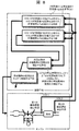
- FIG. 7 is a diagram which is used for explaining start-up fuel injection amount correction value calculation means in the first to third embodiments.
- the figure which is provided for description of the rich control permission flag calculation means in the first to fourth embodiments The figure which is provided for description of the rich correction value calculation means in the first and second embodiments. The figure which is provided for description of the rich correction value update direction flag calculation means in the first embodiment. The figure which is provided for description of the normal air-fuel ratio feedback control means in the first to fourth embodiments. The figure which is provided for description of the rich correction value update direction flag calculation means in the second embodiment. The figure which is provided for description of the rich correction value calculation means in the third embodiment. The figure which is provided for description of the rich correction value update direction flag calculation means in the third embodiment. The figure which is provided for description of the starting fuel injection amount correction value calculating means in the fourth embodiment. The figure which is provided for description of the rich correction value calculation means in the fourth embodiment. The figure which is provided for description of the rich correction value update direction flag calculation means in the fourth embodiment.
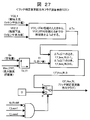
- FIG. 20 is a schematic configuration diagram showing an embodiment of an engine control device according to the present invention (common to the first to fourth examples) together with an example of an in-vehicle engine to which the engine control device is applied.
- the air from outside passes through the air cleaner 1 and flows into the cylinder through the intake manifold 4 and the collector 5.
- the amount of inflow air is adjusted by the electric throttle 3.
- the airflow sensor 2 detects the inflow air amount.
- the intake air temperature sensor 29 detects the intake air temperature.
- the crank angle sensor 15 outputs a signal every 10 ° of the crankshaft rotation angle and a signal every combustion cycle.
- the water temperature sensor 14 detects the coolant temperature of the engine.
- the accelerator opening sensor 13 detects the amount of depression of the accelerator 6 and thereby detects the driver's required torque.
- the vehicle speed is detected by the vehicle speed sensor 30.
- the respective signals (outputs) of the accelerator opening sensor 13, the airflow sensor 2, the intake air temperature sensor 29, the throttle opening sensor 17 attached to the electric throttle 3, the crank angle sensor 15, the water temperature sensor 14, and the vehicle speed sensor 30 are:
- the engine operation state is obtained from the sensor output, and the main operation amount of the engine such as the air amount, the fuel injection amount, and the ignition timing is optimally calculated.
- the fuel injection amount calculated in the control unit 100 is converted into a valve opening pulse signal and sent to the fuel injection valve (injector) 7. Further, a drive signal is sent to the spark plug 8 so as to be ignited at the ignition timing calculated by the control unit 100.
- the injected fuel is mixed with the air from the intake manifold and flows into the cylinder of the engine 9 to form an air-fuel mixture.
- the air-fuel mixture explodes by a spark generated from the spark plug 8 at a predetermined ignition timing, and the piston is pushed down by the combustion pressure to become engine power.
- the exhaust after the explosion is sent to the three-way catalyst 11 through the exhaust manifold 10.
- a part of the exhaust gas is recirculated to the intake side through the exhaust gas recirculation pipe 18.
- the amount of reflux is controlled by a valve 19.
- the control unit 100 normally performs air-fuel ratio feedback control that sequentially corrects the fuel injection amount or the air amount so that the purification efficiency of the three-way catalyst 11 is optimized using the output signals of both the sensors 12 and 20.
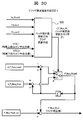
- FIG. 21 shows the internal configuration of the control unit 100.
- the control unit 100 includes an airflow sensor 2, a catalyst upstream O2 sensor 12, an accelerator opening sensor 13, a water temperature sensor 14, an engine speed sensor 15, a throttle valve opening sensor 17, a catalyst downstream O2 sensor 20, an intake air temperature sensor 29, a vehicle speed.
- Each sensor output value of the sensor 30 is input, and after performing signal processing such as noise removal in the input circuit 24, it is sent to the input / output port 25.
- the value of the input port is stored in the RAM 23 and processed in the CPU 21.
- a control program describing the contents of the arithmetic processing is written in the ROM 22 in advance.
- a value representing each actuator operation amount calculated according to the control program is stored in the RAM 23 and then sent to the input / output port 25.
- the ignition plug operation signal is set to ON / OFF signal that is ON when the primary coil in the ignition output circuit is energized and is OFF when the primary coil is not energized. Ignition timing is when it turns from ON to OFF.
- the spark plug signal set at the output port is amplified to a sufficient energy required for combustion by the ignition output circuit 26 and supplied to the spark plug.
- the fuel injection valve drive signal is set to an ON / OFF signal that is ON when the valve is open and OFF when the valve is closed.
- the fuel injection valve drive circuit 27 amplifies the fuel injection valve to an energy sufficient to open the fuel injection valve 7. Sent to.
- a drive signal for realizing the target opening degree of the electric throttle 3 is sent to the electric throttle 3 through the electric throttle drive circuit 28.
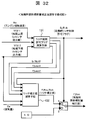
- FIG. 22 is a control system diagram of the first embodiment (common to the second to fourth embodiments).
- the control device of each embodiment includes the following calculation means and control means.
- Basic fuel injection amount calculation means 120 (FIG. 23) ⁇ Start-up fuel injection amount correction value calculation means 130 (FIGS. 24 to 27) Normal air-fuel ratio feedback control means 140 (FIG. 28)
- the basic fuel injection amount calculation means 120 calculates the basic fuel injection amount (Tp).
- the starting fuel injection amount correction value calculation means 130 uses the output values (VO2_1 and VO2_2) of the O2 sensors 12 and 20 before and after the catalyst 11 so that the air-fuel ratio at the time of engine restart is optimized.
- a value (F_Hos) for correcting is calculated. F_Hos is corrected so as to approach the optimum air-fuel ratio at each restart.
- the basic fuel injection amount is corrected by the correction value (Alpha) calculated by the normal time air-fuel ratio feedback control means 140 .
- the calculation means 120 calculates the basic fuel injection amount (Tp). Specifically, the calculation is performed using the equation shown in FIG. Here, Cyl represents the number of cylinders. K0 is determined based on the injector specifications (relationship between fuel injection pulse width and fuel injection amount).
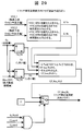
- the calculation means 130 calculates a fuel injection amount correction value (F_Hos) at start-up. Specifically, it is shown in FIG.
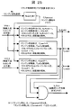
- the rich control permission flag calculation means 131 calculates the start-time rich control permission flag (fp_Rich) from the engine speed (Ne), the catalyst upstream O2 sensor output value (VO2_1), and the catalyst downstream O2 sensor output value (VO2_2), and The fp_Rich0, f_Lean1, and f_Lean2 flags are calculated.
- the catalyst upstream O2 sensor output value (VO2_1), the catalyst downstream O2 sensor output value (VO2_2), the air amount (Qa), the start rich control permission flag (fp_Rich) and fp_Rich0, f_Lean1 , F_Lean2 is used to calculate the rich correction value (F_Hos_Rich).
- the start fuel injection amount correction value (F_Hos) uses the value of the rich correction value (F_Hos_Rich).
- the start time fuel injection amount correction value (F_Hos) is set to 1.0 (the basic fuel injection amount is not corrected).
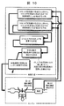
- the calculation means 131 calculates the start-time rich control permission flag (fp_Rich) and the flags fp_Rich0, f_Lean1, and f_Lean2. Specifically, it is shown in FIG.
- A3 is set to 0.7 [V], for example.
- f_Lean1 1.
- TLa1 is set based on the time from the first fuel injection until the catalyst upstream O2 sensor detects the exhaust due to the first combustion. A1 is, for example, 0.9 [V].
- f_Lean2 1.
- TLa2 is set with reference to the time from the first fuel injection until the catalyst downstream O2 sensor detects the exhaust due to the first combustion.
- A2 is, for example, 0.9 [V].
- the start rich control permission flag (fp_Rich) is set to 1. In other cases, the start rich control permission flag (fp_Rich) is set to zero.
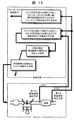
- ⁇ Rich correction value calculation means 132 calculates a rich correction value (F_Hos_Rich).
- F_Hos_Rich a rich correction value
- the calculation means 132 is executed to update the rich correction value (F_Hos_Rich). In other cases, the rich correction value (F_Hos_Rich) maintains the previous value.
- the rich correction value update direction flag calculation means 135 (described later) is rich from the catalyst upstream O2 sensor output value (VO2_1), the catalyst downstream O2 sensor output value (VO2_2), the air amount (Qa), and the fp_Rich0, f_Lean1, and f_Lean2 flags.
- the correction value update direction flag (f_F_Hos_RL) is calculated.
- the rich correction value (F_Hos_Rich) is a value obtained by adding F_Hos_Rich0 to F_Hos_Rich_ini.
- F_Hos_Rich_ini is an initial value of the rich correction value (F_Hos_Rich).
- the rich correction values (d_F_Hos_Lean, d_F_Hos_Rich) updated at each restart are set according to the characteristics of the target engine and the target catalyst in consideration of the correction speed and stability (oscillation property).
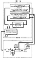
- ⁇ Rich correction value update direction flag calculation means 135 (FIG. 27)>
- the calculation means 135 calculates a rich correction value update direction flag (f_F_Hos_RL). Specifically, it is shown in FIG.
- the time required from when the catalyst upstream O2 sensor output value (VO2_1) exceeds A1 to when the catalyst downstream O2 sensor output value (VO2_2) exceeds A2 is ⁇ Ta.
- T1 is obtained from the air amount (Qa) and the maximum oxygen storage amount (Max_OSC) with reference to the table (Tbl_T1).
- the rich correction value update direction flag (f_F_Hos_RL) uses the value of f_F_hod_RL0. In other cases, the rich correction value update direction flag (f_F_Hos_RL) is set to 0.
- the rich correction value calculation means 132 executes the calculation means 135 when the start-time rich control permission flag (fp_Rich) becomes 1 ⁇ 0, and sets the rich correction value (F_Hos_Rich). Update. In other cases, the rich correction value (F_Hos_Rich) maintains the previous value.
- the start-time rich control permission flag (fp_Rich) is calculated by the rich control permission flag calculating means 131 (FIG. 25). When fp_Rich0 is changed from 1 to 0, or when f_Lean1 is changed from 1 to 0, Alternatively, the start-time rich control permission flag (fp_Rich) is changed from 1 ⁇ 0 at any time when f_Lean2 becomes 1 ⁇ 0.
- the rich correction value update direction flag (f_F_Hos_RL) uses the value of f_F_hod_RL0 (determines whether rich correction or lean correction is performed based on the value of ⁇ Ta).
- the rich correction value update direction flag (f_F_Hos_RL) is set to 0 and rich correction is performed.
- A1 and A2 are set to 0.9 [V], for example.
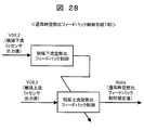
- ⁇ Normal air-fuel ratio feedback control means 140 (FIG. 28)> The control means 140 calculates a normal air-fuel ratio feedback control correction value (Alpha). When the start time rich control permission flag (fp_Rich) is 0 (when the start time fuel injection amount correction is not performed), the control means 140 performs feedback control on the fuel injection amount. Specifically, as shown in FIG. 28, “catalyst downstream air-fuel ratio feedback control” and “catalyst upstream air-fuel ratio feedback control” are not described in detail here because there are many known techniques.
- the next and subsequent times are based only on the required time ⁇ Ta from when the output value of the catalyst upstream O2 sensor 12 exceeds the predetermined value A1 to when the output value of the catalyst downstream O2 sensor exceeds the predetermined value A2.
- the air-fuel ratio at the time of restart was corrected.
- the required time ⁇ Tb from when the output value of the catalyst upstream O2 sensor exceeds the predetermined value B1 to when the output value of the catalyst downstream O2 sensor exceeds the predetermined value B2 is also calculated. By using this, the air-fuel ratio at the next and subsequent restarts is corrected.
- the basic fuel injection amount calculation means 120 (FIG. 23), the starting fuel injection amount correction value calculation means 130 (FIG. 24), and the rich control permission flag calculation means 131 (FIG. 23) described in the first embodiment.
- FIG. 25), the rich correction value calculation means 132 (FIG. 26) and the normal time air-fuel ratio feedback control means 140 (FIG. 28) are basically the same as those in the first embodiment, and will not be described in detail.
- the calculation means 235 calculates a rich correction value update direction flag (f_F_Hos_RL). Specifically, it is shown in FIG.
- the time required from when the catalyst upstream O2 sensor output value (VO2_1) exceeds A1 to when the catalyst downstream O2 sensor output value (VO2_2) exceeds A2 is ⁇ Ta.
- the time required from when the catalyst upstream O2 sensor output value (VO2_1) exceeds B1 to when the catalyst downstream O2 sensor output value (VO2_2) exceeds B2 is ⁇ Tb.
- F_F_hos_RL0 is set to 0 when ⁇ Ta ⁇ T2 and ⁇ Tb ⁇ T3. Otherwise, f_F_hos_RL0 is set to 1.
- T2 and T3 are obtained from the air amount (Qa) and the maximum oxygen storage amount (Max_OSC) with reference to the table (Tbl_T2) and the table (Tbl_T3).
- the rich correction value update direction flag (f_F_Hos_RL) uses the value of f_F_hod_RL0. In other cases, the rich correction value update direction flag (f_F_Hos_RL) is set to 0.
- the rich correction value calculation means 132 executes the calculation means 235 when the start-time rich control permission flag (fp_Rich) changes from 1 to 0, and sets the rich correction value (F_Hos_Rich). Update. In other cases, the rich correction value (F_Hos_Rich) maintains the previous value.
- the start-time rich control permission flag (fp_Rich) is calculated by the “rich control permission flag calculation means (FIG. 25)”, but when fp_Rich0 becomes 1 ⁇ 0 or when f_Lean1 becomes 1 ⁇ 0 Alternatively, at any time when f_Lean2 becomes 1 ⁇ 0, the start time rich control permission flag (fp_Rich) becomes 1 ⁇ 0.
- the rich correction value update direction flag (f_F_Hos_RL) uses the value of f_F_hod_RL0 (determines whether rich correction or lean correction is performed based on the value of ⁇ Ta).
- the rich correction value update direction flag (f_F_Hos_RL) is set to 0 and rich correction is performed.
- A1 and A2 are set to 0.9 [V], for example.
- B1 and B2 are set to, for example, 0.2 [V].
- the required time ⁇ Ta and ⁇ Tb are used to correct the air-fuel ratio at the next and subsequent restarts so that ⁇ Ta is equal to or greater than the predetermined value T2 and ⁇ Tb is equal to or less than the predetermined value T3. did.
- the air-fuel ratio at the next and subsequent restarts is corrected so that the ratio R_ ⁇ T of ⁇ Ta and ⁇ Tb is equal to or greater than a predetermined value R1.
- the basic fuel injection amount calculating means 120 (FIG. 23), the starting fuel injection amount correction value calculating means 130 (FIG. 24), the rich control permission flag calculating means 131 (FIG. 25), and
- the normal-time air-fuel ratio feedback control means 140 (FIG. 28) is basically the same as the first and second embodiments and will not be described in detail.
- ⁇ Rich correction value calculation means 332 (FIG. 30)> The calculation means 332 calculates the rich correction value (F_Hos_Rich). When the start-time rich control permission flag (fp_Rich) is changed from 1 ⁇ 0, as shown in FIG. 30, this calculation means 332 is executed to update the rich correction value (F_Hos_Rich). In other cases, the rich correction value (F_Hos_Rich) maintains the previous value.
- the calculation means 332 is not only the air amount (Qa) in the input value of the rich correction value update direction flag calculation means 335 (described later). The rest is the same. Therefore, detailed description is omitted.
- the calculation means 335 calculates a rich correction value update direction flag (f_F_Hos_RL). Specifically, it is shown in FIG.
- the time required from when the catalyst upstream O2 sensor output value (VO2_1) exceeds A1 to when the catalyst downstream O2 sensor output value (VO2_2) exceeds A2 is ⁇ Ta.
- the time required from when the catalyst upstream O2 sensor output value (VO2_1) exceeds B1 to when the catalyst downstream O2 sensor output value (VO2_2) exceeds B2 is ⁇ Tb.
- the ratio of ⁇ Ta and ⁇ Tb is R_ ⁇ T.
- F_F_hos_RL0 is set to 1 when R_ ⁇ T ⁇ R1. Otherwise, f_F_hos_RL0 is set to 0.
- Threshold R1 is a constant value (no sensitivity to air volume and maximum oxygen storage volume).
- the rich correction value update direction flag (f_F_Hos_RL) uses the value of f_F_hod_RL0. In other cases, the rich correction value update direction flag (f_F_Hos_RL) is set to 0.
- the rich correction value calculation means 332 executes the calculation means 335 when the start-time rich control permission flag (fp_Rich) becomes 1 ⁇ 0, and sets the rich correction value (F_Hos_Rich). Update. In other cases, the rich correction value (F_Hos_Rich) maintains the previous value.
- the start-time rich control permission flag (fp_Rich) is calculated by the “rich control permission flag calculation means (FIG. 25)”, but when fp_Rich0 becomes 1 ⁇ 0 or when f_Lean1 becomes 1 ⁇ 0 Alternatively, at any time when f_Lean2 becomes 1 ⁇ 0, the start time rich control permission flag (fp_Rich) becomes 1 ⁇ 0.
- the rich correction value update direction flag (f_F_Hos_RL) uses the value of f_F_hod_RL0 (determines whether rich correction or lean correction is performed based on the value of ⁇ Ta).
- the rich correction value update direction flag (f_F_Hos_RL) is set to 0 and rich correction is performed.
- A1 and A2 are set to 0.9 [V], for example.
- B1 and B2 are set to, for example, 0.2 [V].
- the basic fuel injection amount calculating means 120 (FIG. 23), the rich control permission flag calculating means 131 (FIG. 25), and the normal air-fuel ratio feedback control means 140 (FIG. 28) Since it is the same as the first to third embodiments, it will not be described in detail.
- the calculation means 430 calculates a start time fuel injection amount correction value (F_Hos). Specifically, it is shown in FIG. Compared to the fuel injection amount correction value calculation unit 130 at the start of the first embodiment (FIG. 24), the catalyst upstream O2 sensor output value (VO2_1) does not exist at the input of the rich correction value calculation unit. is there. Therefore, it is not detailed here.
- ⁇ Rich correction value calculation means 432 calculates a rich correction value (F_Hos_Rich).
- F_Hos_Rich a rich correction value
- the calculation unit 432 is executed to update the rich correction value (F_Hos_Rich). In other cases, the rich correction value (F_Hos_Rich) maintains the previous value.
- the rich correction value update direction flag calculation means 435 calculates the rich correction value update direction flag (f_F_Hos_RL) from the catalyst downstream O2 sensor output value (VO2_2) and the fp_Rich0, f_Lean1, and f_Lean2 flags.
- the rich correction value update direction flag (f_F_Hos_RL) When the rich correction value update direction flag (f_F_Hos_RL) is 2, the previous value of F_Hos_Rich0 is maintained.
- the rich correction value update direction flag (f_F_Hos_RL) When the rich correction value update direction flag (f_F_Hos_RL) is 1, a value obtained by subtracting d_F_Hos_Lean from the previous value of F_Hos_Rich0 is set as the latest F_Hos_Rich0.
- the rich correction value update direction flag (f_F_Hos_RL) When the rich correction value update direction flag (f_F_Hos_RL) is 0, a value obtained by adding only d_F_Hos_Rich to the previous value of F_Hos_Rich0 is set as the latest F_Hos_Rich0.
- the rich correction value (F_Hos_Rich) is a value obtained by adding F_Hos_Rich0 to F_Hos_Rich_ini.
- F_Hos_Rich_ini is an initial value of the rich correction value (F_Hos_Rich).
- the rich correction values (d_F_Hos_Lean, d_F_Hos_Rich) updated at each restart are set according to the characteristics of the target engine and the target catalyst in consideration of the correction speed and stability (oscillation property).
- ⁇ Rich correction value update direction flag calculation means 435 (FIG. 34)>
- the calculation means 435 calculates a rich correction value update direction flag (f_F_Hos_RL). Specifically, it is shown in FIG.
- f_F_hos_RL0 is set to 0 when the catalyst upstream O2 sensor output value (VO2_2) is smaller than A4.
- f_F_hos_RL0 is set to 1.
- f_F_hos_RL0 is set to 2.
- the rich correction value update direction flag (f_F_Hos_RL) uses the value of f_F_hod_RL0. In other cases, the rich correction value update direction flag (f_F_Hos_RL) is set to 0.
- the rich correction value calculation means 432 executes the calculation means 435 when the start-time rich control permission flag (fp_Rich) becomes 1 ⁇ 0, and sets the rich correction value (F_Hos_Rich). Update. In other cases, the rich correction value (F_Hos_Rich) maintains the previous value.
- the start-time rich control permission flag (fp_Rich) is calculated by the rich control permission flag calculation means (FIG. 25), but when fp_Rich0 becomes 1 ⁇ 0, or when f_Lean1 becomes 1 ⁇ 0, or , F_Lean2 becomes 1 ⁇ 0, the start rich control permission flag (fp_Rich) becomes 1 ⁇ 0.
- the rich correction value update direction flag (f_F_Hos_RL) uses the value of f_F_hod_RL0 (determines whether rich correction or lean correction is performed based on the value of ⁇ Ta).
- the rich correction value update direction flag (f_F_Hos_RL) is set to 0 and rich correction is performed.
- A4 is, for example, 0.5 [V].
- A5 is set to 0.9 [V], for example.
- A3 in the rich control permission flag calculation means 131 (FIG. 25) is set to 0.5 [V], for example.
- the air-fuel ratio is controlled to be rich at the time of restart after the idle stop, and further, the outputs of the catalyst upstream / downstream O2 sensors 12 and 20 at that time.
- the atmosphere in the catalyst is estimated, and on the basis of the estimation result, the air-fuel ratio (fuel amount) at the next and subsequent restarts is optimized so that the atmosphere in the catalyst is optimized at the next and subsequent restarts ),
- the atmosphere in the catalyst at the time of restart is optimized each time the restart after the idle stop is repeated, and the purification efficiency of HC and CO is deteriorated at the time of restart Therefore, NOx can be purified with high efficiency, and exhaust deterioration at the time of restart can be effectively suppressed.
- the engine control device of the present invention is an engine control device that mainly performs control at the time of restart after an idle stop, and includes a first oxygen concentration detection means provided upstream of the catalyst and a first oxygen concentration detection device provided downstream of the catalyst. 2, oxygen concentration detecting means, a means for controlling the air-fuel ratio at the time of restarting rich, and when the output value of the first oxygen concentration detecting means falls below a predetermined value A1af at the time of restarting. Means for detecting the required time ⁇ T until the output value of the oxygen concentration detecting means 2 exceeds a predetermined value A2, and means for correcting the air-fuel ratio at the next and subsequent restarts based on the required time ⁇ T. It is characterized by.
- An engine control apparatus is an engine control apparatus that mainly performs control at the time of restart after an idle stop, and includes a second oxygen concentration detection means provided downstream of the catalyst, and an air-fuel ratio at the time of restart.
- the rich control means for controlling the richness of the gas and the restart after the next time so that the output value of the second oxygen concentration detecting means is not less than the predetermined value A4 and not more than the predetermined value A5 within a predetermined time after the restart.
- Air-fuel ratio correction means for correcting the air-fuel ratio at the time.
- the engine control apparatus of the present invention is characterized in that the predetermined value A4 is set to a value of 0.5V or more, and the predetermined value A5 is set to a value of 0.9V or less.
- the engine control apparatus of the present invention is characterized in that, at the time of restart after an idle stop, the air-fuel ratio profile or the minimum value of the air-fuel ratio during the rich control is changed every restart.
- the engine control apparatus provides the first oxygen when the value of the second oxygen concentration detecting means does not exceed the predetermined value A2 even after the predetermined time TLa2 has elapsed after the engine is started or after the first fuel injection. It is characterized by comprising means for permitting feedback control for correcting the fuel injection amount based on the output value of the concentration detection means or the second oxygen concentration detection means.
Landscapes
- Engineering & Computer Science (AREA)
- Chemical & Material Sciences (AREA)
- Combustion & Propulsion (AREA)
- Mechanical Engineering (AREA)
- General Engineering & Computer Science (AREA)
- Electrical Control Of Air Or Fuel Supplied To Internal-Combustion Engine (AREA)
- Combined Controls Of Internal Combustion Engines (AREA)
- Control Of Vehicle Engines Or Engines For Specific Uses (AREA)
Abstract
アイドルストップ後の再始動時において、HCとCOの浄化効率を悪化させることなく、NOxを高効率に浄化できるエンジンの制御装置の提供する。 アイドルストップ後の再始動時に、空燃比をリッチに制御し、触媒上流の第1の酸素濃度検出手段の出力値(VO2_2)が所定値A1を超えたときから、触媒下流の第2の酸素濃度検出手段の出力値(VO2_2)が所定値A2を超えるまでの所要時間ΔTに基づいて、触媒内の雰囲気を推定して、次回以降の再始動時において触媒内の雰囲気が最適となるように、次回以降の再始動時の空燃比を補正する。
Description
本発明は、エンジンの制御装置に関し、特に、燃費改善、CO2排出量低減を目的としてアイドリング時にエンジンを停止するアイドルストップシステムにおいて、アイドルストップ後の再始動時の排気悪化を効果的に抑制することのできるエンジンの制御装置に関するものである。
地球温暖化問題の深刻化、エネルギー問題を背景に、自動車に対して、燃費改善、CO2排出量低減の要求が、これまでになく高まってきている。アイドルストップは、燃費改善、CO2排出量低減に有効である。しかし、アイドルストップ後の再始動時に排気(主にNOx)が悪化する問題がある。これは、触媒に一般に備わるOSC(O2 Storage Capacity)と呼ばれる酸素貯蔵、放出機能によるものである。OSC機能は、ストイキよりリーン雰囲気(酸化雰囲気)では、酸素を貯蔵する機能を持ち、逆に、ストイキよりリッチ雰囲気(還元雰囲気)では、酸素を放出する機能を持つ。このため、アイドルストップ時に燃料噴射を停止すると、空気(酸素濃度が高い)が排気管に流出するため、触媒内がOSC機能により酸素飽和状態(強酸化雰囲気)になる。この状態で、エンジンを再始動すると、エンジンから排出されるガスは、ストイキあるいはリッチであるため、OSC機能により酸素が放出され、触媒内の雰囲気は、強酸化雰囲気からストイキ雰囲気となるものの、その移行期間となる一定期間は、酸化雰囲気であるため、HC、COは、浄化(酸化)されるが、NOxは、浄化(還元)できなくなる。
例えば、下記特許文献1においては、アイドルストップ後の再始動時に、触媒下流の酸素センサがリーンのときは、触媒内の雰囲気がリーンであるとして、リッチ制御を行う方式が開示されている。
特開2006-37964号公報
前述したように、アイドルストップ後の再始動時は、触媒内が強酸化雰囲気であるため、HC、COは、浄化(酸化)されるものの、NOxが浄化(還元)できなくなるので、触媒内を急速に強酸化雰囲気から最適雰囲気に移行させる必要がある。排気空燃比をリッチにして、還元剤を触媒に送ることで、触媒内の酸化雰囲気を弱めることができる。しかし、還元剤を過剰に送り込むと、触媒内は、逆に、還元雰囲気となり、NOxは、高効率に浄化出来るようになるものの、HC、COの浄化効率が著しく低下する。再始動時に、触媒でHC、CO、NOxの全てを高効率に浄化するには、触媒内の雰囲気をストイキ近傍(触媒内のOSCを最適状態)に、できるだけ近づける必要がある。
本発明は、上記事情に鑑みてなされたもので、その目的とするところは、アイドルストップ後の再始動時に、触媒においてHC、CO、NOxの全てを高効率で浄化し得て排気悪化を効果的に抑制することのできるエンジンの制御装置を提供することにある。
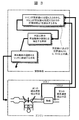
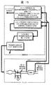
上記目的を達成すべく、本発明に係るエンジンの制御装置は、主としてアイドルストップ後の再始動時の制御を行うもので、その第1態様は、基本的には、図1に示されるように、触媒上流に設けられた第1の酸素濃度検出手段と、触媒下流に設けられた第2の酸素濃度検出手段と、前記再始動時の空燃比をリッチに制御する手段(リッチ制御手段)と、前記再始動時に、前記第1の酸素濃度検出手段の出力値(VO2_1)が所定値A1を超えたときから、前記第2の酸素濃度検出手段の出力値(VO2_2)が所定値A2を超えるまでの所要時間ΔTを検出する手段(所要時間検出手段)と、前記所要時間ΔTに基づいて、次回以降の再始動時の空燃比を補正する手段(空燃比補正手段)と、を備えていることを特徴としている。
この第1態様を以下に詳細に説明する。前述したように、再始動時の排気悪化を抑制するには、触媒内の雰囲気をストイキ近傍(触媒内のOSCを最適状態)に、できるだけ近づける必要があるが、再始動時に空燃比をリッチに制御をした場合、(リッチ側から)触媒内の雰囲気が最適状態に近づくほど、前記所要時間ΔTが長くなる。これは、
1.空燃比に対する排気中の酸素濃度の関係
2.触媒内の酸素貯蔵・放出機能
の2つが影響して起きる。
1.空燃比に対する排気中の酸素濃度の関係
2.触媒内の酸素貯蔵・放出機能
の2つが影響して起きる。
「1.空燃比に対する排気中の酸素濃度の関係」について、まず説明する。空燃比に対する酸素濃度は、ストイキよりリーン側では、空燃比がリーンになるにつれて、ほぼ線形に急激に増加する。具体的には、ストイキ近傍で約0.5%、空燃比18で約4%となる。一方、ストイキよりリッチ側では、酸素濃度は、空燃比がリッチになるにつれ、減ってはいくものの、その感度は小さくなる。具体的には、ストイキで0.5%、空燃比13で約0.1%となる。再始動時において、空燃比を大気の状態からリッチ領域に変化させる場合、排気中の酸素濃度は、大気からストイキになるまでは、20%→0.5%に、ほぼ線形に急激に低下する。しかし、ストイキを越えてリッチ領域に入ると、空燃比が多少リッチになっても、酸素濃度はほとんど低下しなくなる。これが、「1.空燃比に対する排気中の酸素濃度の関係」である。
次に「2.触媒内の酸素貯蔵・放出機能」について説明する。触媒内には、一般に助触媒(セリアなど)と言われる成分が担持されている。この助触媒は、前述したようにOSC機能(酸素を貯蔵・放出する機能)があり、貯蔵されている酸素濃度と触媒に流入してくる排気中の酸素濃度とのバランスで、酸素を貯蔵もしくは放出する。すなわち、
I.(貯蔵されている酸素濃度)>(排気中酸素濃度)のときは、
(貯蔵されている酸素濃度)=(排気中酸素濃度)
となるまで酸素を放出する。
I.(貯蔵されている酸素濃度)>(排気中酸素濃度)のときは、
(貯蔵されている酸素濃度)=(排気中酸素濃度)
となるまで酸素を放出する。
一方、
II.(貯蔵されている酸素濃度)<(排気中酸素濃度)のときは、
(貯蔵されている酸素濃度)=(排気中酸素濃度)
となるまで酸素を貯蔵する。
II.(貯蔵されている酸素濃度)<(排気中酸素濃度)のときは、
(貯蔵されている酸素濃度)=(排気中酸素濃度)
となるまで酸素を貯蔵する。
このことから、空燃比がストイキの状態から、何らかの外乱により、触媒入口の空燃比がリッチになったときは、Iの現象により、触媒内の空燃比がリッチ化するのを防ぎ、もって、HC、COの浄化効率が低下しないようにする。一方、触媒入口の空燃比がリーンになったときは、IIの現象が発生し、触媒内の空燃比がリーン化するのを防ぎ、もって、NOxの浄化効率が低下しないようにする。これが「2.触媒内の酸素貯蔵・放出機能」である。「1.空燃比に対する排気中の酸素濃度の関係」と「2.触媒内の酸素貯蔵・放出機能」により、アイドルストップ後の再始動時、空燃比をストイキよりリッチにすると、触媒前後O2センサ出力は下記のようなプロフィールをとる。再始動前、アイドルストップにより、触媒内のOSCは飽和状態にある(触媒内は大気相当の酸素濃度)。空燃比をストイキよりリッチにした状態で再始動すると、触媒に流入してくる排気中の酸素濃度は、大気相当の20%から0.5%以下にまで低下していく。酸素濃度が低下していくので、上述の「2.触媒内の酸素貯蔵・放出機能」のIの現象により、触媒内の酸素は放出される。このとき、「1.空燃比に対する排気中の酸素濃度の関係」から、ストイキまでは、急激に酸素濃度が低下していくので、OSCに貯蔵されている酸素は急速に放出される。
一方、ストイキを越えてリッチ側になると、酸素濃度は空燃比のリッチ変化に対して、あまり低下していかないので、酸素放出速度も鈍る。リッチ度がストイキ(最適状態)に近いほど、酸素放出速度が遅くなり、「触媒内空燃比」と「流入してくる排気の空燃比」が一致するまで(平衡状態になるまで)の時間は長くなる。流入してくる排気の空燃比は、触媒上流の第1の酸素濃度検出手段(O2センサもしくはA/Fセンサ)で検出可能である。「触媒内空燃比」は、触媒下流の第2の酸素濃度検出手段(O2センサもしくはA/Fセンサ)で検出可能である。したがって、「触媒内空燃比」と「流入してくる排気の空燃比」が一致するまで(平衡状態になるまで)に要する時間ΔTは、例えば、触媒上下流の酸素濃度検出手段がO2センサの場合、触媒上流のO2センサの出力が所定値A1を超えたときから、触媒下流のO2センサの出力が所定値A2を越えるまでに要する時間に相当する。
以上より、前記所要時間ΔTに基づいて、触媒内の雰囲気が最適(ストイキ近傍)となるように再始動時の空燃比が制御されているかどうかを検出することができ、最適でない場合は、次回以降の再始動時の空燃比を補正する。なお、本原理は、触媒上下流の酸素濃度検出手段がいわゆるO2センサであってもA/Fセンサであっても実現可能であるが、第1態様は、触媒上流の酸素濃度検出手段(第1の酸素濃度検出手段)としていわゆるO2センサを用い(この点が次の第2態様と異なる)、触媒下流の酸素濃度検出手段(第2の酸素濃度検出手段)もO2センサを用いた場合に相当する。
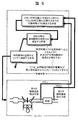
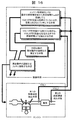
本発明に係るエンジンの制御装置の第2態様は、触媒上流の酸素濃度検出手段(第1の酸素濃度検出手段)として、第1態様とは異なるものを用いた場合で、図2に示されるように、触媒上流に設けられた第1の酸素濃度検出手段と、触媒下流に設けられた第2の酸素濃度検出手段と、再始動時の空燃比をリッチに制御する手段と、前記再始動時に、前記第1の酸素濃度検出手段の出力値(AF_1)が所定値A1afを下回ったときから、前記第2の酸素濃度検出手段の出力値(VO2_2)が所定値A2を超えるまでの所要時間ΔTを検出する手段と、前記所要時間ΔTに基づいて、次回以降の再始動時の空燃比を補正する手段とを備えていることを特徴としている。
すなわち、この第2態様は、触媒上流の酸素濃度検出手段(第1の酸素濃度検出手段)としていわゆるA/Fセンサを用い、触媒下流の酸素濃度検出手段(第2の酸素濃度検出手段)としてO2センサを用いた場合に相当する。
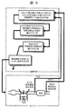
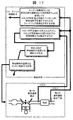
第3態様では、図3に示されるように、第1態様における前記所定値A1および前記所定値A2を0.5V以上の値に設定するようにされる。
すなわち、この第3態様では、触媒上下流センサが共にO2センサである場合において、上述したように、再始動時の空燃比をストイキよりリッチに設定し、触媒上流O2センサの出力値が所定値A1を超えたときから、触媒下流O2センサの出力値が所定値A2を超えるまでの所要時間ΔTを検出するが、このとき、リッチと判定するしきい値として、A1およびA2を、0.5V以上に設定することを規定するものである。
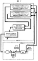
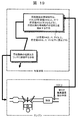
第4態様では、図4に示されるように、前記空燃比補正手段は、第1、2、3態様における前記所要時間ΔTが所定時間T1以上となるように、前記空燃比補正手段は、次回以降の再始動時の空燃比を補正するようにされる。
すなわち、前述したように、リッチ度をストイキ(最適状態)に近づけていくと、「触媒内空燃比」と「流入してくる排気の空燃比」が一致するまで(平衡状態になるまで)の所要時間ΔTは長くなることから、ΔTが所定時間T1以上となったとき、ストイキ(最適状態)近傍に達したと判断するものである。ΔTが所定時間T1以上となるようにするには、空燃比のリッチ度を小さくする(例えば燃料量を少なくする)。
第5態様では、図5に示されるように、第4態様における前記所定時間T1を、前記触媒の最大酸素貯蔵可能量及び吸入空気量うちの少なくとも一方に応じて変える手段を備える。
すなわち、「触媒内空燃比」と「流入してくる排気の空燃比」が一致するまで(平衡状態になるまで)の所要時間ΔTは、リッチ度がストイキに近づくほど長くなるが、それ以外にも、ΔTは、OSC性能(=最大酸素貯蔵可能量)と吸入空気量に感度を持つ。ΔTから、ストイキ(最適状態)近傍にあるか否かを正確に検出するため、それ以外の感度因子である最大酸素貯蔵可能量もしくは吸入空気量に応じて所定時間T1を変えるものである。なお、最大酸素貯蔵可能量(OSC性能)を検出する方式は、従来技術として多数あるので、ここでは詳述しない。
第6態様では、図6に示されるように、上記各態様の構成に加えて、前記所要時間ΔTに基づいて、再始動時の実空燃比と目標空燃比との差を検出する手段を備え、前記空燃比補正手段は、前記差に基づいて、次回以降の再始動時の空燃比を補正するようにされる。
すなわち、前述したように、「触媒内空燃比」と、「流入してくる排気の空燃比」が一致するまで(平衡状態になるまで)の所要時間ΔTは、リッチ度がストイキに近づくほど長くなる。したがって、所要時間ΔTに基づいて、再始動時の実空燃比と目標空燃比との差を検出することも可能である。その差に基づいて、次回以降の再始動時の空燃比が目標空燃比となるように補正するものである。
第7態様では、図7に示されるように、第1、3、4、5、6の各態様において、前記所要時間検出手段として、前記第1の酸素濃度検出手段の出力値(VO2_1)が所定値A1を超えたときから、前記第2の酸素濃度検出手段の出力値(VO2_2)が所定値A2を超えるまでの所要時間ΔTaを検出する手段、及び、前記第1の酸素濃度検出手段の出力値(VO2_1)が所定値B1を越えたときから、前記第2の酸素濃度検出手段の出力値(VO2_2)が所定値B2を越えるまでの所要時間ΔTbを検出する手段を備え、前記空燃比補正手段は、前記ΔTa及び前記ΔTbの少なくとも一方に基づいて、次回以降の再始動時の空燃比を補正するようにされる。
すなわち、前述したように、「触媒内空燃比」と、「流入してくる排気の空燃比」が一致するまで(平衡状態になるまで)の所要時間ΔTは、リッチ度がストイキに近づくほど長くなる。したがって、第3態様の説明でも述べたように、所要時間ΔTを検出する場合、そのしきい値は、ストイキよりリッチ側に設定するのが望ましい。一方、しきい値をリーン側に設定した場合、「流入してくる排気の空燃比」および「触媒内空燃比」がリーン領域にあるときにΔTを検出することを意味する。第1態様の説明で述べたように、リーン領域においては、触媒に流入してくる排気中の酸素濃度が、大気相当の20%から0.5%以下にまで急激に低下していく状態にある。酸素濃度が急激に低下していくので、触媒内(OSC)に貯蔵されている酸素も急激に放出される。すなわち、しきい値をリーン領域に設定すると、ΔTは、OSC(最大酸素貯蔵可能量)と吸入空気量により支配的に決まる。以上から、例えば、所定値A1と所定値A2をリッチ側のしきい値とし、所定値B1と所定値B2をリーン側のしきい値とした場合、リッチ側のしきい値越えの所要時間ΔTaは、前述のように、実空燃比(リッチ度)、最大酸素貯蔵可能量、及び吸入空気量の三つに感度を持ち、リーン側しきい値越えの所要時間ΔTbは、前記実空燃比を除く最大酸素貯蔵可能量と吸入空気量の二つに支配的に感度を持つ。したがって、例えば、ΔTaとΔTbを比較することで、最大酸素貯蔵可能量と吸入空気量の感度をなくし、実空燃比の感度のみを残すことができるため、より精度良く、ストイキ近傍(触媒内のOSCを最適状態)までの誤差を検出することができる。
第8態様では、図8に示されるように、前記所定値A1が前記所定値B1以上の値に設定されるとともに、前記所定値A2が前記所定値B2以上の値に設定され、前記空燃比補正手段は、前記ΔTaが所定値T2以上、かつ、前記ΔTbが所定値T3以下となるように、次回以降の再始動時の空燃比を補正するようにされる。
すなわち、第7態様の説明で述べたように、リッチ側しきい値越えの所要時間ΔTaは、実空燃比(リッチ度)と最大酸素貯蔵可能量と吸入空気量の三つに感度を持ち、リーン側しきい値越えの所要時間ΔTbは、最大酸素貯蔵可能量と吸入空気量の二つに支配的に感度を持つ。したがって、ΔTbが、可能な限り、最大酸素貯蔵可能量と吸入空気量のみに感度を持つようにするため(空燃比の感度を持たないようにするため)、ΔTbはできるだけ短くなるようにする。一方、ΔTaは、可能な限り、実空燃比(リッチ度)に感度を持つようにするため、ΔTaはできるだけ長くなるようにする(∞でもよい)。これを明記するものである。なお、ΔTbが所定値T3以下のとき(最大酸素貯蔵可能量と吸入空気量のみに支配的に感度を持ち、空燃比(リッチ度)にほとんど感度を持たないとき)、ΔTaは、空燃比(リッチ度)の情報を持っているとし、所定値T2以上となるように、次回再始動時の空燃比を補正する(リッチ度を小さくする)のもよい。
第9態様では、図9に示されるように、第7態様の構成に加えて、前記ΔTaと前記ΔTbの比R_ΔTを演算する手段(比演算手段)を備え、前記空燃比補正手段は、前記比R_ΔTに基づいて、次回以降の再始動時の空燃比を補正するようにされる。
すなわち、第7態様の説明で述べたように、リッチ側しきい値越えの所要時間ΔTaは、実空燃比(リッチ度)と最大酸素貯蔵可能量と吸入空気量の三つに感度を持ち、リーン側しきい値越えの所要時間ΔTbは、最大酸素貯蔵可能量と吸入空気量の二つに支配的に感度を持つ。したがって、ΔTaとΔTbの比R_ΔTは、実空燃比(リッチ度)の情報を、より強く持つことになる。具体的には、R_ΔTが大きくなるほど、空燃比はストイキ(最適状態)に近づく。最大酸素貯蔵可能量は、触媒の温度や劣化状態(劣化度)にも依存するので、比R_ΔTを用いることで、これらの感度を少なくすることができる。そのため、より高精度に始動時の空燃比(リッチ度)を検出でき、これにより、一層最適な制御を行えるようになる。これを明記するものである。
第10態様では、図10に示されるように、前記空燃比補正手段は、前記比演算手段により演算された比R_ΔTと所定値R1との差に基づいて、次回以降の再始動時の空燃比を補正するようにされる。
すなわち、第9態様の説明で述べたように、比R_ΔTが大きくなるほど、空燃比はストイキ(最適状態)に近づく。例えば、実空燃比がストイキもしくはその近傍にあるときの比R_ΔTの値を、R1として、これを目標に、次回以降の再始動時の空燃比を補正することを明記するものである。
第11態様では、図11に示されるように、第6~10の各態様における前記所定値A1および前記所定値A2を、0.5V以上の値とし、前記所定値B1および前記所定値B2は、0.5V以下の値に設定するようにされる。
すなわち、第7態様の説明でも述べたように、リッチ側しきい値越えの所要時間ΔTaは、実空燃比(リッチ度)と最大酸素貯蔵可能量と吸入空気量に感度を持ち、リーン側しきい値越えの所要時間ΔTbは、最大酸素貯蔵可能量と吸入空気量に支配的に感度を持つ。触媒上下流酸素濃度検出手段が共にO2センサであるとき、リッチ側しきい値を0.5V以上の値に設定し、リーン側しきい値を0.5以下の値に設定することを規定するものである。
第12態様では、図12に示されるように、前記第2の酸素濃度検出手段の出力値(VO2_2)が所定値A3を越えたとき、前記リッチ制御手段による前記再始動時のリッチ制御を終了させる手段を備える。
すなわち、第1~11の各態様において、リッチ制御を終了する時期として、触媒下流の酸素濃度検出手段(O2センサ)の出力が所定値A3を越えたときと規定するものである。触媒内の雰囲気が、ストイキもしくはリッチな状態になると、触媒下流のO2センサでそれが検出される。それを、所定値A3を越えたときとする。触媒内の雰囲気がストイキもしくはリッチな状態になれば、それ以上リッチなガスを触媒に送る必要はないので、リッチ制御を強制的に終了させる。なお、必ずしもA3≧A2である必要はないことを付記しておく。これは、エンジンの構造上と排気の伝達特性を原因として、燃料噴射により空燃比をリッチにしてから、触媒下流O2センサでリッチであることが検出されるまでには、一定の遅れ時間が存在するためであり、例えば、A3をA3<A2なる値として設定したとしても、前述の遅れ時間により、触媒下流O2センサの出力は、A2にまで達する。
第13態様では、図13に示されるように、第1~12の各態様の構成に加えて、前記第2の酸素濃度検出手段の出力値(VO2_2)が所定値A2を越えた後、前記第1の酸素濃度検出手段及び/又は第2の酸素濃度検出手段の出力値(VO2_1、VO2_2)に基づく燃料噴射量を補正するためのフィードバック制御を許可する手段を備える。
すなわち、第12態様の説明でも述べたように、触媒内の雰囲気がストイキもしくはリッチな状態になれば、それ以上リッチなガスを触媒に送る必要はないので、リッチ制御を終了する。さらに、触媒内を最適状態に保つため、触媒上下流酸素濃度検出手段の出力に基づいた燃料補正を行うべく燃料噴射量についてのフィードバック制御(よく知られている技術)を開始するものである。逆を言えば、リッチ制御中は、触媒上下流酸素濃度検出手段の出力に基づく燃料噴射量についてのフィードバック制御は行わない(禁止する)。
第14態様では、図14に示されるように、第1、第3~13の各態様の構成に加えて、エンジン始動後もしくは最初の燃料噴射後から所定時間TLa1が経過しても、前記第1の酸素濃度検出手段の出力値(VO2_1)が所定値A1を越えていないとき、空燃比をさらにリッチにする手段を備える。
すなわち、始動時の空燃比をリッチにするべく、例えば燃料噴射量を増量補正するが、制御系の誤差等により、実際の空燃比が想定したほど、リッチにならないことがある。このとき、触媒上流O2センサは、所定時間経過しても、リッチ側の信号を出力しない(所定値A1を越えない)。これを検出したときは、触媒内を速やかに最適状態にするため、実空燃比をさらにリッチに補正するものである。
第15態様では、図15に示されるように、第1、第3~13の各態様の構成に加えて、エンジン始動後もしくは最初の燃料噴射後から所定時間TLa1を経過しても、前記第1の酸素濃度検出手段の出力値(VO2_1)が所定値A1を越えていないとき、前記第1の酸素濃度検出手段もしくは第2の酸素濃度検出手段の出力値(VO2_1、VO2_2)に基づく燃料噴射量を補正するためのフィードバック制御を許可する手段を備える。
すなわち、第14態様の説明で述べたように、始動時の空燃比をリッチにするべく、例えば燃料噴射量を増量補正するが、制御系の誤差等により、実際の空燃比が想定したほど、リッチにならないことがある。このとき、触媒上流O2センサは、所定時間経過しても、リッチ側の信号を出力しない(所定値A1を越えない)。これを検出したときは、触媒内を速やかに最適状態にするため、前記燃料噴射量についてのフィードバック制御を開始するものである。
第16態様では、図16に示されるように、第1、第3~13の各態様の構成に加えて、エンジン始動後もしくは最初の燃料噴射後から所定時間TLa2を経過しても、前記第2の酸素濃度検出手段の出力値(VO2_2)が所定値A2を越えていないとき、空燃比をさらにリッチにする手段を備える。
すなわち、始動時の空燃比をリッチにするべく、例えば燃料噴射量を増量補正する。このとき、触媒上流O2センサがリッチ側の信号を(一時的に)出力する程度に、触媒上流の空燃比はリッチになるものの、触媒内の雰囲気を所定時間内にストイキ~リッチの状態にするほど、リッチにならないことがある(触媒下流O2センサ出力が所定値A2を越えない)。これを検出したときは、触媒内を速やかに最適状態にするため、実空燃比をさらにリッチにするものである。
第17態様では、図17に示されるように、第1、第3~13の各態様の構成に加えて、エンジン始動後もしくは最初の燃料噴射後から所定時間TLa2を経過しても、前記第2の酸素濃度検出手段の値が所定値A2を越えていないとき、前記第1の酸素濃度検出手段もしくは第2の酸素濃度検出手段の出力値(VO2_1、VO2_2)に基づく燃料噴射量を補正するためのフィードバック制御を許可する手段を備える。
すなわち、第16態様の説明でも述べたように、始動時の空燃比をリッチにするべく、例えば燃料噴射量を増量補正する。このとき、触媒上流O2センサがリッチ側の信号を(一時的に)出力する程度に、触媒上流の空燃比はリッチになるものの、触媒内の雰囲気を所定時間内にストイキ~リッチの状態にするほど、リッチにならないことがある(触媒下流O2センサ出力が所定値A2を越えない)。これを検出したときは、触媒内を速やかに最適状態にするため、触媒上下流酸素濃度センサ出力に基づいた燃料補正を行うべくフィードバック制御を開始するものである。
本発明に係るエンジンの制御装置の第18態様では、図18に示されるように、触媒下流に設けられた第2の酸素濃度検出手段と、前記再始動時の空燃比をリッチに制御する手段(リッチ制御手段)と、再始動後所定時間内は、前記第2の酸素濃度検出手段の出力値(VO2_2)が所定値A4以上、かつ所定値A5以下となるように、次回以降の再始動時の空燃比を補正する手段(空燃比補正手段)と、を備えていることを特徴としている。
すなわち、始動時の触媒内の雰囲気をストイキ近傍(触媒内のOSCを最適状態)にするために、触媒下流O2センサの出力が所定範囲となるように、次回以降の再始動時の空燃比を補正するものである。触媒内の雰囲気が、ほぼ平衡状態に達しているとき、触媒下流O2センサ出力は、触媒内の雰囲気を示す。したがって、触媒下流O2センサの出力が、ストイキ相当の値(範囲)となるように始動時の空燃比を制御すればよい。
第19態様では、図19に示されるように、第18態様における前記所定値A4を0.5V以上の値に設定し、前記所定値A5を0.9V以下の値に設定するようにされる。
すなわち、第18態様の説明で述べたストイキ相当の値(範囲)を0.5V~0.9Vの範囲と規定するものである。
第20態様では、第1~19の各態様において、アイドルストップ後の再始動時において、前記リッチ制御中の空燃比プロフィールもしくは空燃比の最小値が再始動毎に変化するようにされる。
すなわち、第1~19の各態様においては、再始動する毎に、触媒内の雰囲気が速やかに最適状態となるよう空燃比を補正する。したがって、リッチ制御中の空燃比プロフィールもしくはリッチ制御中の空燃比の最小値(リッチ度)が変化していく。これを明記するものである。
本発明に係るエンジンの制御装置の好ましい態様では、アイドルストップ後の再始動時には、空燃比をリッチに制御し、さらに、そのときの触媒上流酸素濃度検出手段の出力値が所定値A1を超えたときから、触媒下流酸素濃度検出手段の出力値が所定値A2を超えるまでの所要時間ΔTに基づいて、触媒内の雰囲気を推定する。そして、その結果に基づいて、次回以降の再始動時において触媒内の雰囲気が最適となるように、次回以降の再始動時の空燃比(燃料量、空気量)を補正するので、アイドルストップ後の再始動を繰り返す毎に、再始動時の触媒内雰囲気が最適化されるため、再始動時において、HCとCOの浄化効率を悪化させることなく、NOxを高効率に浄化することが可能となり、再始動時の排気悪化を効果的に抑制することができる。
本明細書は、本願の優先権の基礎である日本国特許出願2009-069000号の明細書及び/または図面に記載されている内容を包含する。
2 エアフロセンサ
3 電制スロットル
7 燃料噴射弁
8 点火プラグ
9 エンジン(本体)
11 三元触媒
12 触媒上流O2センサ
15 エンジン回転数センサ
17 スロットル開度センサ
20 触媒下流O2センサ
100 コントロールユニット
120 基本燃料噴射量演算手段
130 始動時燃料噴射量補正値演算手段
131 リッチ制御許可フラグ演算手段
132 リッチ補正値演算手段
135 リッチ補正値更新方向フラグ演算手段
140 通常時空燃比フィードバック制御手段
235 リッチ補正値更新方向フラグ演算手段
332 リッチ補正値演算手段
335 リッチ補正値更新方向フラグ演算手段
430 始動時燃料噴射量補正値演算手段
432 リッチ補正値演算手段
435 リッチ補正値更新方向フラグ演算手段
以下、本発明のエンジンの制御装置の実施の形態を図面を参照しながら説明する。
図20は、本発明に係るエンジンの制御装置の実施形態(第1~第4実施例で共通)を、それが適用された車載用エンジンの一例と共に示す概略構成図である。
図20において、多気筒で構成されるエンジン9では、外部からの空気はエアクリーナ1を通過し、吸気マニホールド4、コレクタ5を経てシリンダー内に流入する。流入空気量は電制スロットル3により調節される。エアフロセンサ2では流入空気量が検出される。また、吸気温センサ29で、吸気温が検出される。クランク角センサ15では、クランク軸の回転角10゜毎の信号と燃焼周期毎の信号が出力される。水温センサ14はエンジンの冷却水温度を検出する。またアクセル開度センサ13は、アクセル6の踏み込み量を検出し、それによって運転者の要求トルクを検出する。車速センサ30で車速を検出する。
アクセル開度センサ13、エアフロセンサ2、吸気温センサ29、電制スロットル3に取り付けられたスロットル開度センサ17、クランク角センサ15、水温センサ14、車速センサ30のそれぞれの信号(出力)は、後述のコントロールユニット100に送られ、これらセンサ出力からエンジンの運転状態を得て、空気量、燃料噴射量、点火時期のエンジンの主要な操作量が最適に演算される。
コントロールユニット100内で演算された燃料噴射量は開弁パルス信号に変換され、燃料噴射弁(インジェクタ)7に送られる。またコントロールユニット100で演算された点火時期で点火されるよう駆動信号が点火プラグ8に送られる。
噴射された燃料は吸気マニホールドからの空気と混合されエンジン9のシリンダー内に流入し混合気を形成する。混合気は所定の点火時期で点火プラグ8から発生される火花により爆発し、その燃焼圧によりピストンを押し下げてエンジンの動力となる。爆発後の排気は排気マニホールド10を経て三元触媒11に送り込まれる。排気還流管18を通って排気の一部は吸気側に還流される。還流量はバルブ19によって制御される。
エンジン(本体)9と三元触媒11の間には、触媒上流O2センサ12が取り付けられている。三元触媒11の下流には、触媒下流O2センサ20が取り付けられている。コントロールユニット100では、通常は、両センサ12、20の出力信号を用いて、三元触媒11の浄化効率が最適となるよう燃料噴射量もしくは空気量を逐次補正する空燃比フィードバック制御を行うが、アイドルストップ後の再始動ときは、本発明に基づく制御を実行する(後で詳述)。
図21は、コントロールユニット100の内部構成を示したものである。コントロールユニット100にはエアフロセンサ2、触媒上流O2センサ12、アクセル開度センサ13、水温センサ14、エンジン回転数センサ15、スロットル弁開度センサ17、触媒下流O2センサ20、吸気温センサ29、車速センサ30の各センサ出力値が入力され、入力回路24にてノイズ除去等の信号処理を行った後、入出力ポート25に送られる。入力ポートの値はRAM23に保管され、CPU21内で演算処理される。演算処理の内容を記述した制御プログラムはROM22に予め書き込まれている。制御プログラムに従って演算された各アクチュエータ作動量を表す値はRAM23に保管された後、入出力ポート25に送られる。点火プラグの作動信号は点火出力回路内の一次側コイルの通流ときはONとなり、非通流ときはOFFとなるON・OFF信号がセットされる。点火時期はONからOFFになる時である。出力ポートにセットされた点火プラグ用の信号は点火出力回路26で燃焼に必要な十分なエネルギーに増幅され点火プラグに供給される。また燃料噴射弁の駆動信号は開弁時ON、閉弁時OFFとなるON・OFF信号がセットされ、燃料噴射弁駆動回路27で燃料噴射弁を開くに十分なエネルギーに増幅され燃料噴射弁7に送られる。電制スロットル3の目標開度を実現する駆動信号は、電制スロットル駆動回路28を経て、電制スロットル3に送られる。
次に、コントロールユニット100が実行する処理内容を実施例毎に具体的に説明する。
[第1実施例]
図22は、第1実施例(第2~第4実施例と共通)の制御システム図である。各実施例の制御装置は、下記の演算手段、制御手段を備えている。
図22は、第1実施例(第2~第4実施例と共通)の制御システム図である。各実施例の制御装置は、下記の演算手段、制御手段を備えている。
・基本燃料噴射量演算手段120(図23)
・始動時燃料噴射量補正値演算手段130(図24~図27)
・通常時空燃比フィードバック制御手段140(図28)
本実施例においては、基本燃料噴射量演算手段120で、基本燃料噴射量(Tp)を演算する。始動時燃料噴射量補正値演算手段130では、触媒11前後のO2センサ12、20の出力値(VO2_1とVO2_2)を用いて、エンジン再始動時の空燃比が最適となるように、燃料噴射量を補正する値(F_Hos)を演算する。F_Hosは、再始動毎に最適空燃比に近づくよう補正される。始動時燃料噴射量補正値演算手段130による再始動時の空燃比補正制御が終了した後は、通常時空燃比フィードバック制御手段140で演算される補正値(Alpha)により、基本燃料噴射量を補正する。
以下に、各演算手段(制御手段)の詳細を述べる。
<基本燃料噴射量演算手段120(図23)>
本演算手段120では、基本燃料噴射量(Tp)を演算する。具体的には、図23に示される式で演算する。ここに、Cylは気筒数を表す。K0は、インジェクタの仕様(燃料噴射パルス幅と燃料噴射量の関係)に基づき決める。
本演算手段120では、基本燃料噴射量(Tp)を演算する。具体的には、図23に示される式で演算する。ここに、Cylは気筒数を表す。K0は、インジェクタの仕様(燃料噴射パルス幅と燃料噴射量の関係)に基づき決める。
<始動時燃料噴射量補正値演算手段130(図24)>
本演算手段130では、始動時燃料噴射量補正値(F_Hos)を演算する。具体的には、図24に示される。
本演算手段130では、始動時燃料噴射量補正値(F_Hos)を演算する。具体的には、図24に示される。
リッチ制御許可フラグ演算手段131(後述)で、エンジン回転速度(Ne)と触媒上流O2センサ出力値(VO2_1)と触媒下流O2センサ出力値(VO2_2)から、始動時リッチ制御許可フラグ(fp_Rich)およびfp_Rich0、f_Lean1、f_Lean2の各フラグを演算する。
リッチ補正値演算手段132(後述)では、触媒上流O2センサ出力値(VO2_1)、触媒下流O2センサ出力値(VO2_2)、空気量(Qa)、始動時リッチ制御許可フラグ(fp_Rich)およびfp_Rich0、f_Lean1、f_Lean2の各フラグから、リッチ補正値(F_Hos_Rich)を演算する。
始動時リッチ制御許可フラグ(fp_Rich)が1のとき、始動時燃料噴射量補正値(F_Hos)は、リッチ補正値(F_Hos_Rich)の値を用いる。始動時リッチ制御許可フラグ(fp_Rich)が0のとき、始動時燃料噴射量補正値(F_Hos)は、1.0とする(基本燃料噴射量に対して補正をしない)。
<リッチ制御許可フラグ演算手段131(図25)>
本演算手段131では、始動時リッチ制御許可フラグ(fp_Rich)およびfp_Rich0、f_Lean1、f_Lean2の各フラグを演算する。具体的には、図25に示される。
本演算手段131では、始動時リッチ制御許可フラグ(fp_Rich)およびfp_Rich0、f_Lean1、f_Lean2の各フラグを演算する。具体的には、図25に示される。
エンジン回転速度(Ne)が、K_NE以上のとき、エンジンは運転状態にある(エンジンは停止していない)として、エンジン運転中フラグ(f_Operated)を1とする。
エンジン停止時(f_Operated=0のとき)は、fp_Rich0=1とする。エンジン始動後(f_Operated=0→1となってから)、VO2_2が、A3以上となったとき、fp_Rich0=1→0とする。それ以外は、前回値を維持する。A3は、例えば、0.7[V]に設定する。
エンジン停止時(f_Operated=0のとき)は、f_Lean1=1とする。エンジン始動後、TLa1[s]経過時、VO2_1がA1以上となっていないとき、f_Lean1=1→0とする。それ以外は、前回値を維持する。TLa1は、最初の燃料噴射から、触媒上流O2センサが最初の燃焼による排気を検出するまでの時間を目安に設定する。A1は、例えば、0.9[V]とする。
エンジン停止時(f_Operated=0のとき)は、f_Lean2=1とする。エンジン始動後、TLa2[s]経過時、VO2_2がA2以上となっていないとき、f_Lean2=1→0とする。それ以外は、前回値を維持する。TLa2は、最初の燃料噴射から、触媒下流O2センサが最初の燃焼による排気を検出するまでの時間を目安に設定する。A2は、例えば、0.9[V]とする。
fp_Rich0=1かつf_Lean1=1かつf_Lean2=1のとき、始動時リッチ制御許可フラグ(fp_Rich)を1にする。それ以外のときは、始動時リッチ制御許可フラグ(fp_Rich)を0にする。
<リッチ補正値演算手段132(図26)>
本演算手段132では、リッチ補正値(F_Hos_Rich)を演算する。始動時リッチ制御許可フラグ(fp_Rich)が1→0となったときに、図26に示されるように、本演算手段132を実行し、リッチ補正値(F_Hos_Rich)を更新する。それ以外のときは、リッチ補正値(F_Hos_Rich)は、前回値を維持する。
本演算手段132では、リッチ補正値(F_Hos_Rich)を演算する。始動時リッチ制御許可フラグ(fp_Rich)が1→0となったときに、図26に示されるように、本演算手段132を実行し、リッチ補正値(F_Hos_Rich)を更新する。それ以外のときは、リッチ補正値(F_Hos_Rich)は、前回値を維持する。
リッチ補正値更新方向フラグ演算手段135(後述)で、触媒上流O2センサ出力値(VO2_1)と触媒下流O2センサ出力値(VO2_2)と空気量(Qa)およびfp_Rich0、f_Lean1、f_Lean2の各フラグからリッチ補正値更新方向フラグ(f_F_Hos_RL)を演算する。
リッチ補正値更新方向フラグ(f_F_Hos_RL)が1のとき、F_Hos_Rich0の前回値に対して、d_F_Hos_Leanだけ減じた値を最新のF_Hos_Rich0とする。リッチ補正値更新方向フラグ(f_F_Hos_RL)が0のとき、F_Hos_Rich0の前回値に対して、d_F_Hos_Richだけ加えた値を最新のF_Hos_Rich0とする。
リッチ補正値(F_Hos_Rich)は、F_Hos_Rich_iniにF_Hos_Rich0を加えた値とする。F_Hos_Rich_iniは、リッチ補正値(F_Hos_Rich)の初期値である。始動時における空燃比制御系の制御誤差などを考慮して、対象エンジンの特性に応じて、適度なリッチ度となるような値に設定する。再始動毎に更新されるリッチ補正値(d_F_Hos_Lean,d_F_Hos_Rich)は、補正速度と安定性(発振性)を考慮して対象エンジンおよび対象触媒の特性に応じて設定する。
<リッチ補正値更新方向フラグ演算手段135(図27)>
本演算手段135では、リッチ補正値更新方向フラグ(f_F_Hos_RL)を演算する。具体的には、図27に示される。
本演算手段135では、リッチ補正値更新方向フラグ(f_F_Hos_RL)を演算する。具体的には、図27に示される。
触媒上流O2センサ出力値(VO2_1)がA1を越えたときから、触媒下流O2センサ出力値(VO2_2)がA2を越えるまでの所要時間をΔTaとする。
ΔTa≦T1のとき、f_F_hos_RL0を1とする。ΔTa≧T1のとき、f_F_hos_RL0を0とする。
T1は、空気量(Qa)および最大酸素貯蔵量(Max_OSC)からテーブル(Tbl_T1)を参照して求める。
f_Lean1=1かつf_Lean2=1で、かつ、fp_Rich0が1→0になったとき、リッチ補正値更新方向フラグ(f_F_Hos_RL)は、f_F_hod_RL0の値を用いる。それ以外のときは、リッチ補正値更新方向フラグ(f_F_Hos_RL)は、0とする。
前述したように、リッチ補正値演算手段132(図26)は、始動時リッチ制御許可フラグ(fp_Rich)が1→0となったときに本演算手段135を実行し、リッチ補正値(F_Hos_Rich)を更新する。それ以外のときは、リッチ補正値(F_Hos_Rich)は、前回値を維持する。始動時リッチ制御許可フラグ(fp_Rich)は、リッチ制御許可フラグ演算手段131(図25)で演算されるが、fp_Rich0が1→0になったとき、もしくは、f_Lean1が1→0になったとき、もしくは、f_Lean2が1→0になったときのいずれかで、始動時リッチ制御許可フラグ(fp_Rich)は、1→0になる。fp_Rich0が1→0となったとき、リッチ補正値更新方向フラグ(f_F_Hos_RL)は、f_F_hod_RL0の値を用いる(ΔTaの値に基づいてリッチ補正するかリーン補正するかを決める)。f_Lean1が1→0あるいはf_Lean2が1→0となったとき、リッチ補正値更新方向フラグ(f_F_Hos_RL)は、0としリッチ補正する。
前述したように、A1,A2は、例えば、0.9[V]とする。
所要時間ΔTaは、実空燃比(リッチ度)以外にも、OSC性能(=最大酸素貯蔵可能量)と吸入空気量に感度を持つため、テーブル(Tbl_T1)は、それを補正するものである。最大酸素貯蔵量(Max_OSC)を求める方法については、公知の技術が多数あるため、ここでは詳述しない。
<通常時空燃比フィードバック制御手段140(図28)>
本制御手段140では、通常時空燃比フィードバック制御補正値(Alpha)を演算する。始動時リッチ制御許可フラグ(fp_Rich)が0のとき(始動時燃料噴射量補正を行っていないとき)、本制御手段140により燃料噴射量についてのフィードバック制御を実行する。具体的には、図28に示されるが、「触媒下流空燃比フィードバック制御」および「触媒上流空燃比フィードバック制御」については、公知の技術が多数あるため、ここでは詳述しない。
本制御手段140では、通常時空燃比フィードバック制御補正値(Alpha)を演算する。始動時リッチ制御許可フラグ(fp_Rich)が0のとき(始動時燃料噴射量補正を行っていないとき)、本制御手段140により燃料噴射量についてのフィードバック制御を実行する。具体的には、図28に示されるが、「触媒下流空燃比フィードバック制御」および「触媒上流空燃比フィードバック制御」については、公知の技術が多数あるため、ここでは詳述しない。
[第2実施例]
上記第1実施例では、触媒上流O2センサ12の出力値が所定値A1を超えたときから、触媒下流O2センサの出力値が所定値A2を超えるまでの所要時間ΔTaのみに基づいて、次回以降の再始動時の空燃比を補正するようにした。本第2実施例では、所要時間ΔTaに加えて、触媒上流O2センサの出力値が所定値B1を超えたときから、触媒下流O2センサの出力値が所定値B2を超えるまでの所要時間ΔTbも用いて、次回以降の再始動時の空燃比を補正するようにされる。なお、ここでは、A1>B1かつA2>B2とする。
上記第1実施例では、触媒上流O2センサ12の出力値が所定値A1を超えたときから、触媒下流O2センサの出力値が所定値A2を超えるまでの所要時間ΔTaのみに基づいて、次回以降の再始動時の空燃比を補正するようにした。本第2実施例では、所要時間ΔTaに加えて、触媒上流O2センサの出力値が所定値B1を超えたときから、触媒下流O2センサの出力値が所定値B2を超えるまでの所要時間ΔTbも用いて、次回以降の再始動時の空燃比を補正するようにされる。なお、ここでは、A1>B1かつA2>B2とする。
本第2実施例においては、第1実施例で説明した基本燃料噴射量演算手段120(図23)、始動時燃料噴射量補正値演算手段130(図24)、リッチ制御許可フラグ演算手段131(図25)、リッチ補正値演算手段132(図26)、及び、通常時空燃比フィードバック制御手段140(図28)は、基本的には第1実施例と同じであるので、詳述しない。
以下、第1実施例のものとは異なるリッチ補正値更新方向フラグ演算手段235を説明する。
<リッチ補正値更新方向フラグ演算手段235(図29)>
本演算手段235では、リッチ補正値更新方向フラグ(f_F_Hos_RL)を演算する。具体的には、図29に示される。
本演算手段235では、リッチ補正値更新方向フラグ(f_F_Hos_RL)を演算する。具体的には、図29に示される。
触媒上流O2センサ出力値(VO2_1)がA1を越えたときから、触媒下流O2センサ出力値(VO2_2)がA2を越えるまでの所要時間をΔTaとする。
触媒上流O2センサ出力値(VO2_1)がB1を越えたときから、触媒下流O2センサ出力値(VO2_2)がB2を越えるまでの所要時間をΔTbとする。
ΔTa≧T2かつΔTb≦T3のとき、f_F_hos_RL0を0とする。それ以外のときは、f_F_hos_RL0を1とする。
T2およびT3は、空気量(Qa)および最大酸素貯蔵量(Max_OSC)からテーブル(Tbl_T2)およびテーブル(Tbl_T3)を参照して求める。
f_Lean1=1かつf_Lean2=1で、かつ、fp_Rich0が1→0になったとき、リッチ補正値更新方向フラグ(f_F_Hos_RL)は、f_F_hod_RL0の値を用いる。それ以外のときは、リッチ補正値更新方向フラグ(f_F_Hos_RL)は、0とする。
前述したように、リッチ補正値演算手段132(図26)は、始動時リッチ制御許可フラグ(fp_Rich)が1→0となったときに本演算手段235を実行し、リッチ補正値(F_Hos_Rich)を更新する。それ以外のときは、リッチ補正値(F_Hos_Rich)は、前回値を維持する。始動時リッチ制御許可フラグ(fp_Rich)は、「リッチ制御許可フラグ演算手段(図25)」で演算されるが、fp_Rich0が1→0になったとき、もしくは、f_Lean1が1→0になったとき、もしくは、f_Lean2が1→0になったときのいずれかで、始動時リッチ制御許可フラグ(fp_Rich)は、1→0になる。fp_Rich0が1→0となったとき、リッチ補正値更新方向フラグ(f_F_Hos_RL)は、f_F_hod_RL0の値を用いる(ΔTaの値に基づいてリッチ補正するかリーン補正するかを決める)。f_Lean1が1→0あるいはf_Lean2が1→0となったとき、リッチ補正値更新方向フラグ(f_F_Hos_RL)は、0としリッチ補正する。
前述したように、A1,A2は、例えば、0.9[V]とする。また、B1,B2は、例えば、0.2[V]とする。
ΔTaおよびΔTbは、実空燃比(リッチ度)以外にも、OSC性能(=最大酸素貯蔵可能量)と吸入空気量に感度を持つため、テーブル(Tbl_T2)およびテーブル(Tbl_T3)は、それを補正するものである。最大酸素貯蔵量(Max_OSC)を求める方法については、公知の技術が多数あるため、ここでは詳述しない。
[第3実施例]
上記第2実施例では、所要時間ΔTaとΔTbを用いて、ΔTaが所定値T2以上、かつ、ΔTbが所定値T3以下となるように、次回以降の再始動時の空燃比を補正するようにした。本第3実施例では、ΔTaとΔTbの比R_ΔTが所定値R1以上となるように、次回以降の再始動時の空燃比を補正するようにされる。
上記第2実施例では、所要時間ΔTaとΔTbを用いて、ΔTaが所定値T2以上、かつ、ΔTbが所定値T3以下となるように、次回以降の再始動時の空燃比を補正するようにした。本第3実施例では、ΔTaとΔTbの比R_ΔTが所定値R1以上となるように、次回以降の再始動時の空燃比を補正するようにされる。
本第3実施例においては、前述した基本燃料噴射量演算手段120(図23)、始動時燃料噴射量補正値演算手段130(図24)、リッチ制御許可フラグ演算手段131(図25)、及び、通常時空燃比フィードバック制御手段140(図28)は、基本的には第1、第2実施例と同じであるので、詳述しない。
以下、第1、第2実施例のものとは異なるリッチ補正値演算手段332、リッチ補正値更新方向フラグ演算手段335を説明する。
<リッチ補正値演算手段332(図30)>
本演算手段332では、リッチ補正値(F_Hos_Rich)を演算する。始動時リッチ制御許可フラグ(fp_Rich)が1→0となったときに、図30に示されるように、本演算手段332を実行し、リッチ補正値(F_Hos_Rich)を更新する。それ以外のときは、リッチ補正値(F_Hos_Rich)は、前回値を維持する。本演算手段332は、第1実施例のリッチ補正値演算手段132(図26)に対して、リッチ補正値更新方向フラグ演算手段335(後述)の入力値に空気量(Qa)が無いだけで、それ以外は、同じである。したがって、詳述は省略する。
本演算手段332では、リッチ補正値(F_Hos_Rich)を演算する。始動時リッチ制御許可フラグ(fp_Rich)が1→0となったときに、図30に示されるように、本演算手段332を実行し、リッチ補正値(F_Hos_Rich)を更新する。それ以外のときは、リッチ補正値(F_Hos_Rich)は、前回値を維持する。本演算手段332は、第1実施例のリッチ補正値演算手段132(図26)に対して、リッチ補正値更新方向フラグ演算手段335(後述)の入力値に空気量(Qa)が無いだけで、それ以外は、同じである。したがって、詳述は省略する。
<リッチ補正値更新方向フラグ演算手段335(図31)>
本演算手段335では、リッチ補正値更新方向フラグ(f_F_Hos_RL)を演算する。具体的には、図31に示される。
本演算手段335では、リッチ補正値更新方向フラグ(f_F_Hos_RL)を演算する。具体的には、図31に示される。
触媒上流O2センサ出力値(VO2_1)がA1を越えたときから、触媒下流O2センサ出力値(VO2_2)がA2を越えるまでの所要時間をΔTaとする。
触媒上流O2センサ出力値(VO2_1)がB1を越えたときから、触媒下流O2センサ出力値(VO2_2)がB2を越えるまでの所要時間をΔTbとする。
ΔTaとΔTbの比をR_ΔTとする。
R_ΔT≦R1のとき、f_F_hos_RL0を1とする。それ以外のときは、f_F_hos_RL0を0とする。
しきいR1は、一定値とする(空気量、最大酸素貯蔵量に感度を持たない)。
f_Lean1=1かつf_Lean2=1で、かつ、fp_Rich0が1→0になったとき、リッチ補正値更新方向フラグ(f_F_Hos_RL)は、f_F_hod_RL0の値を用いる。それ以外のときは、リッチ補正値更新方向フラグ(f_F_Hos_RL)は、0とする。
前述したように、リッチ補正値演算手段332(図30)は、始動時リッチ制御許可フラグ(fp_Rich)が1→0となったときに本演算手段335を実行し、リッチ補正値(F_Hos_Rich)を更新する。それ以外のときは、リッチ補正値(F_Hos_Rich)は、前回値を維持する。
始動時リッチ制御許可フラグ(fp_Rich)は、「リッチ制御許可フラグ演算手段(図25)」で演算されるが、fp_Rich0が1→0になったとき、もしくは、f_Lean1が1→0になったとき、もしくは、f_Lean2が1→0になったときのいずれかで、始動時リッチ制御許可フラグ(fp_Rich)は、1→0になる。fp_Rich0が1→0となったとき、リッチ補正値更新方向フラグ(f_F_Hos_RL)は、f_F_hod_RL0の値を用いる(ΔTaの値に基づいてリッチ補正するかリーン補正するかを決める)。f_Lean1が1→0あるいはf_Lean2が1→0となったとき、リッチ補正値更新方向フラグ(f_F_Hos_RL)は、0としリッチ補正する。
前述したように、A1,A2は、例えば、0.9[V]とする。また、B1,B2は、例えば、0.2[V]とする。
[第4実施例]
上記第1実施例では、触媒上流O2センサ12の出力値が所定値A1を超えたときから、触媒下流O2センサの出力値が所定値A2を超えるまでの所要時間ΔTaに基づいて、次回以降の再始動時の空燃比を補正するようにした。本第4実施例では、触媒下流O2センサ20の出力値が所定範囲に入るように、次回以降の再始動時の空燃比を補正するようにされる。
上記第1実施例では、触媒上流O2センサ12の出力値が所定値A1を超えたときから、触媒下流O2センサの出力値が所定値A2を超えるまでの所要時間ΔTaに基づいて、次回以降の再始動時の空燃比を補正するようにした。本第4実施例では、触媒下流O2センサ20の出力値が所定範囲に入るように、次回以降の再始動時の空燃比を補正するようにされる。
本第4実施例においては、前述した基本燃料噴射量演算手段120(図23)、リッチ制御許可フラグ演算手段131(図25)、及び、通常時空燃比フィードバック制御手段140(図28)は、基本的には第1~第3実施例と同じであるので、詳述しない。
以下、第1~第3実施例のものとは異なる始動時燃料噴射量補正値演算手段430、リッチ補正値演算手段432、リッチ補正値更新方向フラグ演算手段435を説明する。
<始動時燃料噴射量補正値演算手段430(図32)>
本演算手段430では、始動時燃料噴射量補正値(F_Hos)を演算する。具体的には、図32に示される。第1実施例の始動時燃料噴射量補正値演算手段130(図24)に対して、リッチ補正値演算手段の入力に触媒上流O2センサ出力値(VO2_1)が無いだけで、それ以外は同じである。したがって、ここでは、詳述しない。
本演算手段430では、始動時燃料噴射量補正値(F_Hos)を演算する。具体的には、図32に示される。第1実施例の始動時燃料噴射量補正値演算手段130(図24)に対して、リッチ補正値演算手段の入力に触媒上流O2センサ出力値(VO2_1)が無いだけで、それ以外は同じである。したがって、ここでは、詳述しない。
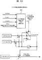
<リッチ補正値演算手段432(図33)>
本演算手段432では、リッチ補正値(F_Hos_Rich)を演算する。始動時リッチ制御許可フラグ(fp_Rich)が1→0となったときに、図33に示されるように、本演算手段432を実行し、リッチ補正値(F_Hos_Rich)を更新する。それ以外のときは、リッチ補正値(F_Hos_Rich)は、前回値を維持する。
本演算手段432では、リッチ補正値(F_Hos_Rich)を演算する。始動時リッチ制御許可フラグ(fp_Rich)が1→0となったときに、図33に示されるように、本演算手段432を実行し、リッチ補正値(F_Hos_Rich)を更新する。それ以外のときは、リッチ補正値(F_Hos_Rich)は、前回値を維持する。
リッチ補正値更新方向フラグ演算手段435(後述)で、触媒下流O2センサ出力値(VO2_2)およびfp_Rich0、f_Lean1、f_Lean2の各フラグからリッチ補正値更新方向フラグ(f_F_Hos_RL)を演算する。
リッチ補正値更新方向フラグ(f_F_Hos_RL)が2のとき、F_Hos_Rich0の前回値を維持する。リッチ補正値更新方向フラグ(f_F_Hos_RL)が1のとき、F_Hos_Rich0の前回値に対して、d_F_Hos_Leanだけ減じた値を最新のF_Hos_Rich0とする。リッチ補正値更新方向フラグ(f_F_Hos_RL)が0のとき、F_Hos_Rich0の前回値に対して、d_F_Hos_Richだけ加えた値を最新のF_Hos_Rich0とする。
リッチ補正値(F_Hos_Rich)は、F_Hos_Rich_iniにF_Hos_Rich0を加えた値とする。F_Hos_Rich_iniは、リッチ補正値(F_Hos_Rich)の初期値である。始動時における空燃比制御系の制御誤差などを考慮して、対象エンジンの特性に応じて、適度なリッチ度となるような値に設定する。再始動毎に更新されるリッチ補正値(d_F_Hos_Lean,d_F_Hos_Rich)は、補正速度と安定性(発振性)を考慮して対象エンジンおよび対象触媒の特性に応じて設定する。
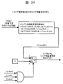
<リッチ補正値更新方向フラグ演算手段435(図34)>
本演算手段435では、リッチ補正値更新方向フラグ(f_F_Hos_RL)を演算する。具体的には、図34に示される。
本演算手段435では、リッチ補正値更新方向フラグ(f_F_Hos_RL)を演算する。具体的には、図34に示される。
エンジン始動後所定時間内は、触媒上流O2センサ出力値(VO2_2)がA4より小さいとき、f_F_hos_RL0を0とする。触媒上流O2センサ出力値(VO2_2)がA5より大きいとき、f_F_hos_RL0を1とする。触媒上流O2センサ出力値(VO2_2)がA4以上、かつA5以下のとき、f_F_hos_RL0を2とする。
f_Lean1=1かつf_Lean2=1で、かつ、fp_Rich0が1→0になったとき、リッチ補正値更新方向フラグ(f_F_Hos_RL)は、f_F_hod_RL0の値を用いる。それ以外のときは、リッチ補正値更新方向フラグ(f_F_Hos_RL)は、0とする。
前述したように、リッチ補正値演算手段432(図33)は、始動時リッチ制御許可フラグ(fp_Rich)が1→0となったときに本演算手段435を実行し、リッチ補正値(F_Hos_Rich)を更新する。それ以外のときは、リッチ補正値(F_Hos_Rich)は、前回値を維持する。始動時リッチ制御許可フラグ(fp_Rich)は、リッチ制御許可フラグ演算手段(図25)で演算されるが、fp_Rich0が1→0になったとき、もしくは、f_Lean1が1→0になったとき、もしくは、f_Lean2が1→0になったときのいずれかで、始動時リッチ制御許可フラグ(fp_Rich)は、1→0になる。
fp_Rich0が1→0となったとき、リッチ補正値更新方向フラグ(f_F_Hos_RL)は、f_F_hod_RL0の値を用いる(ΔTaの値に基づいてリッチ補正するかリーン補正するかを決める)。
f_Lean1が1→0あるいはf_Lean2が1→0となったとき、リッチ補正値更新方向フラグ(f_F_Hos_RL)は、0としリッチ補正する。
A4は、例えば、0.5[V]とする。また、A5は、例えば、0.9[V]とする。これに合わせて、リッチ制御許可フラグ演算手段131(図25)におけるA3は、例えば、0.5[V]に設定する。
[実施形態の作用効果]
以上の説明から理解されるように、本発明実施形態の制御装置では、アイドルストップ後の再始動時には、空燃比をリッチに制御し、さらに、そのときの触媒上下流O2センサ12、20の出力値に基づいて、触媒内の雰囲気を推定し、その推定結果に基づいて、次回以降の再始動時において触媒内の雰囲気が最適となるように、次回以降の再始動時の空燃比(燃料量、空気量)を補正するようにされるので、アイドルストップ後の再始動を繰り返す毎に、再始動時の触媒内雰囲気が最適化され、再始動時において、HCとCOの浄化効率を悪化させることなく、NOxを高効率に浄化することが可能となり、再始動時の排気悪化を効果的に抑制することができる。
以上の説明から理解されるように、本発明実施形態の制御装置では、アイドルストップ後の再始動時には、空燃比をリッチに制御し、さらに、そのときの触媒上下流O2センサ12、20の出力値に基づいて、触媒内の雰囲気を推定し、その推定結果に基づいて、次回以降の再始動時において触媒内の雰囲気が最適となるように、次回以降の再始動時の空燃比(燃料量、空気量)を補正するようにされるので、アイドルストップ後の再始動を繰り返す毎に、再始動時の触媒内雰囲気が最適化され、再始動時において、HCとCOの浄化効率を悪化させることなく、NOxを高効率に浄化することが可能となり、再始動時の排気悪化を効果的に抑制することができる。
本発明のエンジン制御装置は、主としてアイドルストップ後の再始動時の制御を行うエンジンの制御装置であって、触媒上流に設けられた第1の酸素濃度検出手段と、触媒下流に設けられた第2の酸素濃度検出手段と、再始動時の空燃比をリッチに制御する手段と、前記再始動時に、前記第1の酸素濃度検出手段の出力値が所定値A1afを下回ったときから、前記第2の酸素濃度検出手段の出力値が所定値A2を超えるまでの所要時間ΔTを検出する手段と、前記所要時間ΔTに基づいて、次回以降の再始動時の空燃比を補正する手段とを備えていることを特徴とする。
本発明のエンジン制御装置は、主としてアイドルストップ後の再始動時の制御を行うエンジンの制御装置であって、触媒下流に設けられた第2の酸素濃度検出手段と、前記再始動時の空燃比をリッチに制御するリッチ制御手段と、再始動後所定時間内は、前記第2の酸素濃度検出手段の出力値が所定値A4以上、かつ所定値A5以下となるように、次回以降の再始動時の空燃比を補正する空燃比補正手段と、を備えていることを特徴とする。
本発明のエンジン制御装置は、前記所定値A4が0.5V以上の値に設定され、前記所定値A5が0.9V以下の値に設定されていることを特徴とする。
本発明のエンジン制御装置は、アイドルストップ後の再始動時において、前記リッチ制御中の空燃比プロフィールもしくは空燃比の最小値が再始動毎に変化するようにされていることを特徴とする。
本発明のエンジン制御装置は、エンジン始動後もしくは最初の燃料噴射後から所定時間TLa2を経過しても、第2の酸素濃度検出手段の値が所定値A2を越えていないとき、第1の酸素濃度検出手段もしくは第2の酸素濃度検出手段の出力値に基づく燃料噴射量を補正するためのフィードバック制御を許可する手段を備えていることを特徴とする。
Claims (15)
- 主としてアイドルストップ後の再始動時の制御を行うエンジンの制御装置であって、
触媒上流に設けられた第1の酸素濃度検出手段と、
触媒下流に設けられた第2の酸素濃度検出手段と、
前記再始動時の空燃比をリッチに制御するリッチ制御手段と、
前記再始動時に、前記第1の酸素濃度検出手段の出力値が所定値A1を超えたときから、前記第2の酸素濃度検出手段の出力値が所定値A2を超えるまでの所要時間ΔTを検出する所要時間検出手段と、
前記所要時間ΔTに基づいて、次回以降の再始動時の空燃比を補正する空燃比補正手段と、
を備えていることを特徴とするエンジンの制御装置。 - 前記所定値A1および前記所定値A2が0.5V以上の値に設定されていることを特徴とする請求項1に記載のエンジンの制御装置。
- 前記空燃比補正手段は、前記所要時間ΔTが所定時間T1以上となるように、次回以降の再始動時の空燃比を補正することを特徴とする請求項1に記載のエンジンの制御装置。
- 前記所定時間T1を、前記触媒の最大酸素貯蔵可能量及び吸入空気量のうちの少なくとも一方に応じて変える手段を備えていることを特徴とする請求項3に記載のエンジンの制御装置。
- 前記所要時間ΔTに基づいて、再始動時の実空燃比と目標空燃比との差を検出する手段を備え、
前記空燃比補正手段は、前記差に基づいて、次回以降の再始動時の空燃比を補正するようにされていることを特徴とする請求項1に記載のエンジンの制御装置。 - 前記所要時間検出手段として、前記第1の酸素濃度検出手段の出力値が所定値A1を超えたときから、前記第2の酸素濃度検出手段の出力値が所定値A2を超えるまでの所要時間ΔTaを検出する手段、及び、前記第1の酸素濃度検出手段の出力値が所定値B1を越えたときから、前記第2の酸素濃度検出手段の出力値が所定値B2を越えるまでの所要時間ΔTbを検出する手段を備え、
前記空燃比補正手段は、前記所要時間ΔTa及び前記所要時間ΔTbのうちの少なくとも一方に基づいて、次回以降の再始動時の空燃比を補正することを特徴とする請求項1に記載のエンジンの制御装置。 - 前記所定値A1が前記所定値B1以上の値に設定されるとともに、前記所定値A2が前記所定値B2以上の値に設定され、
前記空燃比補正手段は、前記所要時間ΔTaが所定値T2以上、かつ、前記所要時間ΔTbが所定値T3以下となるように、次回以降の再始動時の空燃比を補正するようにされていることを特徴とする請求項6に記載のエンジンの制御装置。 - 前記所要時間ΔTaと前記所要時間ΔTbの比R_ΔTを演算する比演算手段を備え、
前記空燃比補正手段は、前記比R_ΔTに基づいて、次回以降の再始動時の空燃比を補正することを特徴とする請求項6に記載のエンジンの制御装置。 - 前記空燃比補正手段は、前記比演算手段により演算された比R_ΔTと所定値R1との差に基づいて、次回以降の再始動時の空燃比を補正することを特徴とする請求項8に記載のエンジンの制御装置。
- 前記所定値A1および前記所定値A2が0.5V以上の値に設定され、前記所定値B1および前記所定値B2が0.5V以下の値に設定されていることを特徴とする請求項5に記載のエンジンの制御装置。
- 前記第2の酸素濃度検出手段の出力値が所定値A3を越えたとき、前記リッチ制御手段による前記再始動時のリッチ制御を終了させる手段を備えていることを特徴とする請求項1に記載のエンジンの制御装置。
- 前記第2の酸素濃度検出手段の出力値が所定値A2を越えた後、前記第1の酸素濃度検出手段及び/又は第2の酸素濃度検出手段の出力値に基づく燃料噴射量を補正するためのフィードバック制御を許可する手段を備えていることを特徴とする請求項1に記載のエンジンの制御装置。
- エンジン始動後もしくは最初の燃料噴射後から所定時間TLa1が経過しても、前記第1の酸素濃度検出手段の出力値が所定値A1を越えていないとき、空燃比をさらにリッチにする手段を備えていることを特徴とする請求項1に記載のエンジンの制御装置。
- エンジン始動後もしくは最初の燃料噴射後から所定時間TLa1を経過しても、前記第1の酸素濃度検出手段の出力値が所定値A1を越えていないとき、前記第1の酸素濃度検出手段もしくは第2の酸素濃度検出手段の出力値に基づく燃料噴射量を補正するためのフィードバック制御を許可する手段を備えていることを特徴とする請求項1に記載のエンジンの制御装置。
- エンジン始動後もしくは最初の燃料噴射後から所定時間TLa2を経過しても、前記第2の酸素濃度検出手段の出力値が所定値A2を越えていないとき、空燃比をさらにリッチにする手段を備えていることを特徴とする請求項1に記載のエンジンの制御装置。
Priority Applications (3)
| Application Number | Priority Date | Filing Date | Title |
|---|---|---|---|
| EP10753337.4A EP2410157A4 (en) | 2009-03-19 | 2010-02-04 | Control device for engine |
| US13/202,350 US8463532B2 (en) | 2009-03-19 | 2010-02-04 | Control device for engine |
| CN201080008676.5A CN102325983B (zh) | 2009-03-19 | 2010-02-04 | 发动机的控制装置 |
Applications Claiming Priority (2)
| Application Number | Priority Date | Filing Date | Title |
|---|---|---|---|
| JP2009069000A JP5031789B2 (ja) | 2009-03-19 | 2009-03-19 | エンジンの制御装置 |
| JP2009-069000 | 2009-03-19 |
Publications (1)
| Publication Number | Publication Date |
|---|---|
| WO2010106842A1 true WO2010106842A1 (ja) | 2010-09-23 |
Family
ID=42739508
Family Applications (1)
| Application Number | Title | Priority Date | Filing Date |
|---|---|---|---|
| PCT/JP2010/051582 WO2010106842A1 (ja) | 2009-03-19 | 2010-02-04 | エンジンの制御装置 |
Country Status (5)
| Country | Link |
|---|---|
| US (1) | US8463532B2 (ja) |
| EP (1) | EP2410157A4 (ja) |
| JP (1) | JP5031789B2 (ja) |
| CN (1) | CN102325983B (ja) |
| WO (1) | WO2010106842A1 (ja) |
Families Citing this family (5)
| Publication number | Priority date | Publication date | Assignee | Title |
|---|---|---|---|---|
| JP5031789B2 (ja) * | 2009-03-19 | 2012-09-26 | 日立オートモティブシステムズ株式会社 | エンジンの制御装置 |
| EP2667003B1 (en) * | 2011-01-18 | 2020-04-08 | Toyota Jidosha Kabushiki Kaisha | Air-fuel ratio control device for internal combustion engine |
| WO2014064791A1 (ja) * | 2012-10-25 | 2014-05-01 | 三菱重工業株式会社 | ディーゼルエンジン制御装置 |
| JP5623578B2 (ja) * | 2013-03-22 | 2014-11-12 | ヤマハ発動機株式会社 | 燃料噴射制御装置 |
| CN114263521B (zh) * | 2021-12-31 | 2023-03-21 | 潍柴动力股份有限公司 | 一种传感器参数的修正方法及装置 |
Citations (6)
| Publication number | Priority date | Publication date | Assignee | Title |
|---|---|---|---|---|
| JPH10141117A (ja) * | 1996-11-05 | 1998-05-26 | Nissan Motor Co Ltd | エンジンの空燃比制御装置 |
| JP2001115879A (ja) * | 1999-10-14 | 2001-04-24 | Denso Corp | 触媒劣化状態検出装置 |
| JP2006037964A (ja) | 2004-07-27 | 2006-02-09 | Ford Global Technologies Llc | 再起動時のNOx排出量を制御するシステム |
| JP2007198352A (ja) * | 2006-01-30 | 2007-08-09 | Hitachi Ltd | 内燃機関の燃料噴射制御装置 |
| JP2008190477A (ja) * | 2007-02-07 | 2008-08-21 | Nissan Motor Co Ltd | エンジンの空燃比制御装置及びハイブリッド車の制御装置 |
| JP2009069000A (ja) | 2007-09-13 | 2009-04-02 | Ntn Corp | センサユニット |
Family Cites Families (7)
| Publication number | Priority date | Publication date | Assignee | Title |
|---|---|---|---|---|
| JPS5535181A (en) * | 1978-09-05 | 1980-03-12 | Nippon Denso Co Ltd | Air fuel ratio control device |
| JP2000054826A (ja) * | 1998-08-11 | 2000-02-22 | Nissan Motor Co Ltd | エンジンの排気浄化装置 |
| JP3606211B2 (ja) * | 2000-02-22 | 2005-01-05 | 日産自動車株式会社 | エンジンの排気浄化装置 |
| JP3815256B2 (ja) * | 2001-05-29 | 2006-08-30 | トヨタ自動車株式会社 | 車輌用間歇運転内燃機関のNOx排出抑制運転方法 |
| JP4511954B2 (ja) * | 2005-01-12 | 2010-07-28 | トヨタ自動車株式会社 | 内燃機関の燃料噴射制御装置 |
| JP4747809B2 (ja) * | 2005-11-30 | 2011-08-17 | 日産自動車株式会社 | エンジンの排気浄化装置 |
| JP5031789B2 (ja) * | 2009-03-19 | 2012-09-26 | 日立オートモティブシステムズ株式会社 | エンジンの制御装置 |
-
2009
- 2009-03-19 JP JP2009069000A patent/JP5031789B2/ja not_active Expired - Fee Related
-
2010
- 2010-02-04 WO PCT/JP2010/051582 patent/WO2010106842A1/ja active Application Filing
- 2010-02-04 EP EP10753337.4A patent/EP2410157A4/en not_active Withdrawn
- 2010-02-04 US US13/202,350 patent/US8463532B2/en not_active Expired - Fee Related
- 2010-02-04 CN CN201080008676.5A patent/CN102325983B/zh not_active Expired - Fee Related
Patent Citations (6)
| Publication number | Priority date | Publication date | Assignee | Title |
|---|---|---|---|---|
| JPH10141117A (ja) * | 1996-11-05 | 1998-05-26 | Nissan Motor Co Ltd | エンジンの空燃比制御装置 |
| JP2001115879A (ja) * | 1999-10-14 | 2001-04-24 | Denso Corp | 触媒劣化状態検出装置 |
| JP2006037964A (ja) | 2004-07-27 | 2006-02-09 | Ford Global Technologies Llc | 再起動時のNOx排出量を制御するシステム |
| JP2007198352A (ja) * | 2006-01-30 | 2007-08-09 | Hitachi Ltd | 内燃機関の燃料噴射制御装置 |
| JP2008190477A (ja) * | 2007-02-07 | 2008-08-21 | Nissan Motor Co Ltd | エンジンの空燃比制御装置及びハイブリッド車の制御装置 |
| JP2009069000A (ja) | 2007-09-13 | 2009-04-02 | Ntn Corp | センサユニット |
Non-Patent Citations (1)
| Title |
|---|
| See also references of EP2410157A4 * |
Also Published As
| Publication number | Publication date |
|---|---|
| CN102325983B (zh) | 2014-05-28 |
| US8463532B2 (en) | 2013-06-11 |
| EP2410157A4 (en) | 2018-02-28 |
| CN102325983A (zh) | 2012-01-18 |
| JP2010223023A (ja) | 2010-10-07 |
| US20110315108A1 (en) | 2011-12-29 |
| EP2410157A1 (en) | 2012-01-25 |
| JP5031789B2 (ja) | 2012-09-26 |
Similar Documents
| Publication | Publication Date | Title |
|---|---|---|
| JP3966014B2 (ja) | 内燃機関の排気浄化装置 | |
| JP4664395B2 (ja) | エンジンの制御装置 | |
| JP5348190B2 (ja) | 内燃機関の制御装置 | |
| JP2011027059A (ja) | エンジンの制御装置 | |
| JP5278454B2 (ja) | 多気筒内燃機関の気筒間空燃比ばらつき異常検出装置 | |
| JP2004316523A (ja) | 内燃機関の空燃比制御装置 | |
| JP5031789B2 (ja) | エンジンの制御装置 | |
| WO2019198546A1 (ja) | 空燃比制御装置 | |
| JP4244824B2 (ja) | 内燃機関の燃料噴射制御装置 | |
| JP2008240675A (ja) | 内燃機関の制御装置 | |
| JP2000130221A (ja) | 内燃機関の燃料噴射制御装置 | |
| JP2006097514A (ja) | エンジンの空燃比制御装置 | |
| JP4269279B2 (ja) | 内燃機関の制御装置 | |
| JP4321406B2 (ja) | 内燃機関の燃料供給量制御装置 | |
| JP5331931B2 (ja) | 内燃機関の空燃比制御装置 | |
| JP5077047B2 (ja) | 内燃機関の制御装置 | |
| US10253720B2 (en) | Control device for internal combustion engine | |
| JP2004232477A (ja) | 内燃機関の制御装置 | |
| JP2017115802A (ja) | 内燃機関の空燃比制御装置 | |
| JP5886002B2 (ja) | 内燃機関の制御装置 | |
| JPH08291739A (ja) | 空燃比制御装置 | |
| JP5723747B2 (ja) | 内燃機関の制御装置 | |
| JP4446873B2 (ja) | 内燃機関の空燃比制御装置 | |
| JP2012159003A (ja) | 内燃機関の制御方法 | |
| JP2006083795A (ja) | 内燃機関の空燃比制御装置 |
Legal Events
| Date | Code | Title | Description |
|---|---|---|---|
| WWE | Wipo information: entry into national phase |
Ref document number: 201080008676.5 Country of ref document: CN |
|
| 121 | Ep: the epo has been informed by wipo that ep was designated in this application |
Ref document number: 10753337 Country of ref document: EP Kind code of ref document: A1 |
|
| WWE | Wipo information: entry into national phase |
Ref document number: 2010753337 Country of ref document: EP |
|
| WWE | Wipo information: entry into national phase |
Ref document number: 13202350 Country of ref document: US |
|
| NENP | Non-entry into the national phase |
Ref country code: DE |