WO2010106825A1 - 光ファイバの着色装置の洗浄方法および光ファイバの着色装置 - Google Patents
光ファイバの着色装置の洗浄方法および光ファイバの着色装置 Download PDFInfo
- Publication number
- WO2010106825A1 WO2010106825A1 PCT/JP2010/050183 JP2010050183W WO2010106825A1 WO 2010106825 A1 WO2010106825 A1 WO 2010106825A1 JP 2010050183 W JP2010050183 W JP 2010050183W WO 2010106825 A1 WO2010106825 A1 WO 2010106825A1
- Authority
- WO
- WIPO (PCT)
- Prior art keywords
- optical fiber
- die
- cleaning
- cleaning liquid
- nipple
- Prior art date
Links
Images


Classifications
-
- B—PERFORMING OPERATIONS; TRANSPORTING
- B08—CLEANING
- B08B—CLEANING IN GENERAL; PREVENTION OF FOULING IN GENERAL
- B08B9/00—Cleaning hollow articles by methods or apparatus specially adapted thereto
-
- B—PERFORMING OPERATIONS; TRANSPORTING
- B29—WORKING OF PLASTICS; WORKING OF SUBSTANCES IN A PLASTIC STATE IN GENERAL
- B29D—PRODUCING PARTICULAR ARTICLES FROM PLASTICS OR FROM SUBSTANCES IN A PLASTIC STATE
- B29D11/00—Producing optical elements, e.g. lenses or prisms
- B29D11/00865—Applying coatings; tinting; colouring
- B29D11/00894—Applying coatings; tinting; colouring colouring or tinting
- B29D11/00903—Applying coatings; tinting; colouring colouring or tinting on the surface
-
- C—CHEMISTRY; METALLURGY
- C03—GLASS; MINERAL OR SLAG WOOL
- C03C—CHEMICAL COMPOSITION OF GLASSES, GLAZES OR VITREOUS ENAMELS; SURFACE TREATMENT OF GLASS; SURFACE TREATMENT OF FIBRES OR FILAMENTS MADE FROM GLASS, MINERALS OR SLAGS; JOINING GLASS TO GLASS OR OTHER MATERIALS
- C03C25/00—Surface treatment of fibres or filaments made from glass, minerals or slags
- C03C25/10—Coating
-
- C—CHEMISTRY; METALLURGY
- C03—GLASS; MINERAL OR SLAG WOOL
- C03C—CHEMICAL COMPOSITION OF GLASSES, GLAZES OR VITREOUS ENAMELS; SURFACE TREATMENT OF GLASS; SURFACE TREATMENT OF FIBRES OR FILAMENTS MADE FROM GLASS, MINERALS OR SLAGS; JOINING GLASS TO GLASS OR OTHER MATERIALS
- C03C25/00—Surface treatment of fibres or filaments made from glass, minerals or slags
- C03C25/70—Cleaning, e.g. for reuse
-
- G—PHYSICS
- G02—OPTICS
- G02B—OPTICAL ELEMENTS, SYSTEMS OR APPARATUS
- G02B6/00—Light guides; Structural details of arrangements comprising light guides and other optical elements, e.g. couplings
- G02B6/02—Optical fibres with cladding with or without a coating
-
- G—PHYSICS
- G02—OPTICS
- G02B—OPTICAL ELEMENTS, SYSTEMS OR APPARATUS
- G02B6/00—Light guides; Structural details of arrangements comprising light guides and other optical elements, e.g. couplings
- G02B6/44—Mechanical structures for providing tensile strength and external protection for fibres, e.g. optical transmission cables
- G02B6/4479—Manufacturing methods of optical cables
- G02B6/4482—Code or colour marking
Definitions
- the present invention relates to an optical fiber coloring device cleaning method and an optical fiber coloring device for coloring a resin coating of an optical fiber.
- the resin coating of the optical fiber is colored differently for each optical fiber for the purpose of identification or the like.
- the optical fiber is colored by passing the optical fiber through a coloring device.
- the optical fiber is colored using a single coloring device even when different colors are colored.
- the coloring device is washed to wash out the ink, an ink of a different color is supplied, and another optical fiber is colored (for example, see Patent Document 1). ).
- By washing such a coloring device it is possible to prevent inks of different colors from being mixed and to achieve a desired color.
- a resin coating apparatus for forming a high-quality resin coating with a high drawing speed in the step of forming a resin coating on an optical fiber is disclosed (for example, see Patent Document 2).
- the resin coating apparatus disclosed in Patent Document 2 includes a nipple through which an optical fiber sequentially passes, a first die, and a second die.
- a resin pool is formed on the outer periphery of the nipple, and the nipple, the first die, and the second die.
- a resin flow path is formed between the dies, and the optical fiber passage hole of the second die has a tapered portion whose inner diameter decreases in the optical fiber passage direction.
- this resin coating apparatus when resin is supplied to the resin reservoir from the outside, the resin is supplied to the outer periphery of the optical fiber through the resin flow path and is coated. At this time, it is supposed that the resin is stably coated by the optical fiber passage hole of the second die having a tapered portion. Note that such a structure of the resin coating apparatus is considered to be effective even when a high-quality coloring is performed in a coloring apparatus in a state where the passing speed of the optical fiber is high.
- the present invention has been made in view of the above, and it is an object of the present invention to provide a cleaning method for an optical fiber coloring device and an optical fiber coloring device capable of improving the productivity of an optical fiber and reducing the manufacturing cost.
- a cleaning method for an optical fiber coloring device includes a nipple, a first die, a second die, and an outer periphery of the nipple that sequentially pass the optical fiber.
- An ink reservoir is formed between the nipple, the first die, and the second die, and an ink flow path is provided between the nipple, the first die, and the second die.
- the optical fiber passage hole of the second die formed is a cleaning method for an optical fiber coloring device having a tapered portion whose inner diameter decreases in the optical fiber passing direction.
- the cleaning liquid is supplied from the ink supply port, characterized in that it comprises a and a second cleaning step of discharging from the optical fiber passing hole of said second die with.
- the optical fiber coloring device cleaning method is the optical fiber coloring device according to the present invention, wherein, after the first cleaning step and the second cleaning step, the coloring device includes an optical fiber passage hole and the ink. Air is supplied from a supply port, and the cleaning liquid is discharged from the cleaning liquid discharge port, and the coloring device is supplied with air from the optical fiber passage hole of the nipple and the ink supply port, And a second cleaning liquid discharging step of discharging the cleaning liquid from the optical fiber passage hole of the second die.
- the optical fiber coloring apparatus cleaning method according to the present invention is the above-described invention, wherein the first die has a plurality of notches on an outer periphery, and the first cleaning step and the second cleaning step The cleaning liquid is circulated through the connecting hole structure formed by the notch portion of the first die.
- the method for cleaning an optical fiber coloring device according to the present invention is characterized in that the number of notches in the first die is three or more.
- An optical fiber coloring device includes a nipple having a first optical fiber passage hole that allows an optical fiber to pass therethrough, and a second light that is positioned below the nipple and communicates with the first optical fiber passage hole.
- a first die having a fiber passage hole, a plurality of cutouts on the outer periphery, and a lower portion of the first die, communicating with the second optical fiber passage hole, and having an inner diameter facing the optical fiber passage direction.
- An ink reservoir is formed between the second die having a third optical fiber passage hole having a taper portion that decreases and an outer periphery of the nipple, and an ink supply port and a cleaning liquid discharge port connected to the ink reservoir
- An ink flow path is formed between the nipple, the first die, and the second die, and the ink reservoir is formed by a plurality of cutout portions of the first die. Ri, ink flow path, wherein the communication hole structures sequentially communicating the internal tapered portion is formed.
- the optical fiber coloring device is characterized in that, in the above-mentioned invention, the number of the cutout portions of the first die is three or more.
- the optical fiber coloring device can be cleaned quickly, it is possible to improve the productivity of the optical fiber and reduce the manufacturing cost.
- FIG. 1 is a schematic cross-sectional view of an optical fiber coloring apparatus according to Embodiment 1.
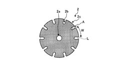
- FIG. 2 is a schematic plan view of the first die shown in FIG.
- FIG. 3 is an explanatory view for explaining a cleaning method of the coloring apparatus shown in FIG.
- FIG. 4 is an explanatory view for explaining a cleaning method of the coloring apparatus shown in FIG.
- FIG. 5 is a schematic plan view of another embodiment of the first die that can be used in the coloring apparatus shown in FIG. 1.
- FIG. 6 is a schematic plan view of still another embodiment of the first die that can be used in the coloring apparatus shown in FIG. 1.
- FIG. 1 is a schematic cross-sectional view of an optical fiber coloring device according to Embodiment 1 of the present invention.
- the coloring device 10 includes a nipple 1, a first die 2, a second die 3, and a frame body 4.
- FIG. 2 is a schematic plan view of the first die 2 shown in FIG.
- the coloring apparatus 10 will be described in detail with reference to FIGS. 1 and 2.
- the nipple 1 has an optical fiber passage hole 1a through which an optical fiber passes.
- the optical fiber passage hole 1a has a tapered portion 1b having an inner diameter that decreases in the optical fiber passage direction.
- the first die 2 is located below the nipple 1 and is a disc-like one that is held between the frame 4 and the second die 3 and passes through an optical fiber that communicates with the optical fiber passage hole 1a. It has a hole 2a. Moreover, the 1st die
- dye 2 has the some notch part 2b in the outer periphery, The protrusion part 2c is formed by this, and it has a gear shape.
- the outer side than the broken line L is a region sandwiched between the frame body 4 and the second die 3.
- the maximum width W in the circumferential direction of the protrusion 2c is preferably 3 mm or less, for example. If the width W is 3 mm or less, ink is hardly left after washing in the region sandwiched between the frame 4 and the second die 3 of the projection 2c of the first die 2, and sufficient cleaning properties are ensured. .
- region A inside the broken line L ie, the area
- S is preferably 1.0 times or less the area of the optical fiber passage hole 2a.
- the second die 3 is located below the first die 2 and has an optical fiber passage hole 3a communicating with the optical fiber passage hole 2a.
- the optical fiber passage hole 3a includes a first inner diameter portion 3b, a second inner diameter portion 3c, and a tapered portion 3d whose inner diameter decreases in the optical fiber passing direction.
- the first die 2 is held in the first inner diameter portion 3b of the second die 3.
- the frame 4 is located between the nipple 1 and the first die 2 and the second die 3 and has a substantially cylindrical shape. Further, an ink reservoir 5 a is formed on the outer periphery of the nipple 1 by the inner wall 4 a of the frame 4 and the outer peripheral wall 1 c of the nipple 1. Further, the frame 4 has an ink supply port 4b and a cleaning liquid discharge port 4c formed so as to be connected to the ink reservoir 5a.
- the frame 4 is provided with a gap between the nipple 1 and the first die 2, whereby the ink flow path 5b is formed. Further, an ink flow path 5c is formed between the first die 2 and the second die 3 and inside the second inner diameter portion 3c. In addition, a communication hole structure 5e is formed to sequentially communicate the ink reservoir 5a, the ink flow path 5c, and the taper portion inside 5d.
- the communication hole structure 5e is realized by a hole formed by the first inner diameter portion 3b of the second die 3 and the cutout portion 2b of the first die 2.
- ink of a desired color is supplied to the coloring device 10 from the ink supply port 4b.
- the flow path connected to the outside of the cleaning liquid discharge port 4c is closed so that the ink does not flow out of the coloring device 10 from the cleaning liquid discharge port 4c.
- the optical fibers coated with resin are sequentially passed through the optical fiber passage holes 1a to 3a of the nipple 1, the first die 2 and the second die 3 at a high speed of, for example, 1500 m / min or more. Then, the optical fiber is colored.
- the viscosity of the ink used here is desirably 3 Pa ⁇ s or less in the coloring device 10 in consideration of the applicability to the optical fiber.
- the temperature of the ink is room temperature, but the ink may be heated to adjust the viscosity of the ink.
- FIGS. 3 and 4 are explanatory diagrams for explaining a cleaning method of the coloring apparatus 10 shown in FIG. 3 shows the first and second cleaning steps, and FIG. 4 shows the first and second cleaning liquid discharge steps.
- the solid line connected to each valve indicates piping.
- Reference numerals 31 and 32 denote connection jigs for connecting the pipe to the optical fiber passage hole 1a or the optical fiber passage hole 3a.
- the cleaning liquid 34 is stored in the tank 33, and the valves V2, V3, V6, and V7 are opened while the valve V1 is opened and air is supplied to the tank 33.
- the cleaning liquid 34 is supplied to the coloring device 10 from the ink supply port 4b and the optical fiber passage hole 1a.
- the arrows Ar1 and Ar2 indicate the flow of the cleaning liquid 34.
- the valve V4 connected to the optical fiber passage hole 3a is closed.
- the cleaning liquid 34 is discharged from the cleaning liquid discharge port 4c, flows through the pipe as indicated by the arrow Ar3, and is stored as the waste liquid 36 in the tank 35 decompressed by the ejector.
- the ink cleaning liquid 34 an organic solvent such as ethyl alcohol, acetone, or MEK (methyl ethyl ketone) is generally used, but ethyl alcohol is desirable from the viewpoint of toxicity, handleability, and economy.
- the cleaning effect is obtained by using ethyl alcohol having relatively low solubility as the cleaning liquid 34.
- a solvent such as acetone or MEK having higher solubility is used as the cleaning liquid 34, it goes without saying that the cleaning effect is further improved.
- the angle formed by the ink supply port 4b and the cleaning liquid discharge port 4c centering on the optical fiber passage holes 1a to 3a is 180 degrees, but if it is 120 degrees to 180 degrees, It is preferable because the flow of the cleaning liquid 34 is good and cleaning can be performed in a shorter time.
- the valve V3 is closed and the valve V4 is opened.
- the cleaning liquid 34 is discharged from the optical fiber passage hole 3a, flows through the piping as indicated by the arrow Ar4, and is stored in the tank 35 as the waste liquid 36.
- the ink reservoir 5a and the taper portion inside 5d are separated, the ink easily remains in the taper portion inside 5d only by the first cleaning step, and the cleaning time is increased. It takes. Therefore, in the second cleaning step, the cleaning liquid 34 is not discharged from the cleaning liquid discharge port 4c by closing the valve V3, and the cleaning liquid 34 is discharged from the optical fiber passage hole 3a by opening the valve V4.
- the interior 5d can be sufficiently cleaned in a short time.
- the cleaning liquid 34 that passes through the ink reservoir 5a is in a clean state without being mixed with ink.
- the cleaning efficiency of the taper portion inside 5d is further improved.
- the coloring device 10 may be heated. At this time, the temperature of the coloring device 10 is desirably set to be equal to or lower than the boiling point of the cleaning liquid 34 so that the cleaning liquid 34 does not boil.
- the valves V1 and V2 are closed, and the supply of the cleaning liquid 34 is stopped.
- the valve V5 is opened to supply air to the coloring device 10 from the ink supply port 4b and the optical fiber passage hole 1a.
- the valve V3 is opened and the valve V4 is closed.
- the cleaning liquid 34 inside the coloring device 10, in particular, the ink reservoir 5 a is discharged.
- the cleaning liquid 34 is discharged from the cleaning liquid discharge port 4c, flows through the piping as indicated by the arrow Ar5, and is stored in the tank 35 as the waste liquid 36.
- the valve V3 is closed and the valve V4 is opened.
- the cleaning liquid 34 is discharged from the optical fiber passage hole 3a, flows through the piping as indicated by the arrow Ar6, and is stored as the waste liquid 36 in the tank 35.
- the cleaning liquid 34 inside the tapered portion 5d can be sufficiently discharged.
- the pressure of the air supplied to discharge the cleaning liquid 34 from the coloring device 10 is 0.2 MPa or more in terms of gauge pressure.
- heated air may be supplied.
- the cleaning liquid 34 in the ink reservoir 5a is discharged in the first cleaning liquid discharging process and then the cleaning liquid 34 in the tapered portion 5d is sufficiently discharged in the second cleaning liquid discharging process, the cleaning liquid 34 is efficiently discharged. Can be discharged. For example, if the valve V3 and the valve V4 are opened at the same time, and the cleaning liquid 34 is simultaneously discharged from the cleaning liquid discharge port 4c and the optical fiber passage hole 3a, the air pressure in the ink reservoir 5a becomes low, and the inside of the tapered portion 5d The cleaning liquid cannot be discharged sufficiently, or it takes time to discharge the cleaning liquid.
- the first and second cleaning steps, the first and second cleaning liquid discharging steps may be performed once, but the steps from the first cleaning step to the second cleaning liquid discharging step are repeated a plurality of times, for example, three times.
- the coloring device 10 can be more sufficiently cleaned.
- the coloring device 10 can be cleaned quickly, the cleaning time is shortened, and the amount of cleaning liquid used is greatly reduced. Further, since such a cleaning process is performed every time the color of the optical fiber is changed, the effects of shortening the time and reducing the amount of cleaning liquid used are extremely great. Therefore, according to the cleaning method described above, it is possible to improve the productivity of the optical fiber and significantly reduce the manufacturing cost.
- dye 2 has the notch part 2b, The 1st internal diameter part 3b of the 2nd die
- a communication hole structure 5e is realized in which the ink reservoir 5a, the ink flow path 5c, and the inside of the tapered portion 5d are sequentially communicated by the hole formed by the notch 2b.
- the cleaning liquid 34 circulates in the communication hole structure 5e in each of the above-described processes, particularly the second cleaning process and the second cleaning liquid discharge process, and the inside of the taper portion from the ink reservoir 5a.
- the cleaning liquid 34 can flow along the wall surfaces of the first inner diameter portion 3b and the second inner diameter portion 3c of the second die 3 in the direction toward 5d, the vicinity of the joint portion between the first die 2 and the second die 3 Even in the corner portion, the flow of the cleaning liquid 34 does not stagnate. As a result, the ink in this corner portion is also quickly washed away, and a shorter cleaning time is realized.
- the steps from the first cleaning step to the second cleaning liquid discharging step are performed on the coloring apparatus having the structure shown in FIG. 1, sufficient cleaning is performed in about 3 minutes. I was able to.
- the following cleaning process was performed on a coloring apparatus having a structure without a cleaning liquid discharge port in the coloring apparatus shown in FIG. That is, first, a cleaning process was performed in which the cleaning liquid was supplied from the optical fiber passage hole and the ink supply port of the nipple and the cleaning liquid was discharged from the optical fiber passage hole of the second die.
- a cleaning liquid discharging step was performed in which air was supplied from the optical fiber passage hole of the nipple and the ink supply port, and the cleaning liquid was discharged from the optical fiber passage hole of the second die. In this case, it took 10 minutes or more to complete the sufficient cleaning.
- FIG. 5 is a schematic plan view of another embodiment of the first die that can be used in the coloring apparatus 10 shown in FIG.
- the first die 6 has an optical fiber passage hole 6a, and the number of notches 6b is three.
- the number of notches 6b is three or more, three or more protrusions 6c are formed, and the first die 6 is preferably held stably.
- FIG. 6 is a schematic plan view of still another embodiment of the first die that can be used in the coloring apparatus 10 shown in FIG.
- the first die 7 has an optical fiber passage hole 7 a, but unlike the first dies 2 and 6, a plurality of holes 7 b are formed.
- the communication hole structure 5e that sequentially communicates the ink reservoir 5a, the ink flow path 5c, and the tapered portion inside 5d is realized by a plurality of holes 7b. Even when the first die 7 having such a shape is used, it is clear that the cleaning method of the coloring device 10 is effective.
- the coloring apparatus 10 shown in FIG. 1 has one ink supply port 4b and one cleaning liquid discharge port 4c, but the number of ink supply ports and cleaning liquid discharge ports is not particularly limited. You may have.
- the optical fiber coloring device cleaning method and the optical fiber coloring device according to the present invention are suitable for use in coloring the optical fiber resin coating.
Abstract
光ファイバを順次通過させるニップルと第一ダイと第二ダイと、ニップルの外周との間にインク溜まりを形成するとともに、該インク溜まりに連結するインク供給口および洗浄液排出口を有する枠体とを備え、ニップル、第一ダイ、および第二ダイの間にはインク流路が形成され、第二ダイの光ファイバ通過孔は、内径が光ファイバの通過方向に向かって減少しているテーパ部を有する光ファイバの着色装置の洗浄方法であって、ニップルの光ファイバ通過孔とインク供給口とから洗浄液を供給し、洗浄液排出口から排出させる第一洗浄工程と、ニップルの光ファイバ通過孔とインク供給口とから洗浄液を供給し、第二ダイの光ファイバ通過孔から排出させる第二洗浄工程と、を含む。これによって、光ファイバの生産性の向上および製造コストの低減を実現できる光ファイバの着色装置の洗浄方法および着色装置を提供する。
Description
本発明は、光ファイバの樹脂被覆を着色するための光ファイバの着色装置の洗浄方法および光ファイバの着色装置に関するものである。
光ファイバの樹脂被覆には、識別等の目的で、光ファイバごとに異なる色の着色が成されている。光ファイバの着色は、着色装置に光ファイバを通過させて行なう。また、通常、光ファイバの着色は、異なる色の着色を行う際にも、1つの着色装置を用いて行なう。そして、ある光ファイバをある色のインクにより着色をした後に、着色装置を洗浄してインクを洗い流し、異なる色のインクを供給し、別の光ファイバの着色を行なっている(たとえば特許文献1参照)。このような着色装置の洗浄を行なうことによって、異なる色のインクが混ざり合うことを防止し、所望の色の着色を実現している。
一方、光ファイバに樹脂被覆を形成する工程において、線引き速度を高速にした状態で高品質の樹脂被覆を形成するための樹脂被覆装置が開示されている(たとえば特許文献2参照)。特許文献2に開示される樹脂被覆装置は、光ファイバを順次通過させるニップルと第一ダイと第二ダイとを備え、ニップルの外周に樹脂溜まりが形成され、ニップル、第一ダイ、および第二ダイの間には樹脂流路が形成され、第二ダイの光ファイバ通過孔は、その内径が光ファイバの通過方向に向かって減少しているテーパ部を有するものである。この樹脂被覆装置においては、外部から樹脂溜まりに樹脂が供給されると、樹脂流路を通って光ファイバの外周に樹脂が供給され、被覆される。この際、第二ダイの光ファイバ通過孔がテーパ部を有することによって、樹脂が安定して被覆されるとされている。なお、このような樹脂被覆装置の構造は、着色装置において、光ファイバの通過速度を高速にした状態で高品質の着色を行なう場合にも有効と考えられる。
しかしながら、上述したように、光ファイバの着色装置の場合には、着色する色を変更する際に洗浄を行う。この洗浄の際に、着色装置が上記高速線引き用の樹脂被覆装置のように複雑な構造とすると、洗浄に時間がかかるので、通過速度を高速化したにもかかわらず、光ファイバの生産性の低下および製造コストの増加を引き起こすという問題があった。
本発明は、上記に鑑みてなされたものであって、光ファイバの生産性の向上および製造コストの低減を実現できる光ファイバの着色装置の洗浄方法および光ファイバの着色装置を提供することを目的とする。
上述した課題を解決し、目的を達成するために、本発明に係る光ファイバの着色装置の洗浄方法は、光ファイバを順次通過させるニップルと第一ダイと第二ダイと、前記ニップルの外周との間にインク溜まりを形成するとともに、該インク溜まりに連結するインク供給口および洗浄液排出口を有する枠体とを備え、前記ニップル、第一ダイ、および第二ダイの間にはインク流路が形成され、前記第二ダイの光ファイバ通過孔は、内径が光ファイバの通過方向に向かって減少しているテーパ部を有する光ファイバの着色装置の洗浄方法であって、前記着色装置に、前記ニップルの光ファイバ通過孔と前記インク供給口とから洗浄液を供給し、前記洗浄液排出口から排出させる第一洗浄工程と、前記着色装置に、前記ニップルの光ファイバ通過孔と前記インク供給口とから洗浄液を供給し、前記第二ダイの光ファイバ通過孔から排出させる第二洗浄工程と、を含むことを特徴とする。
また、本発明に係る光ファイバの着色装置の洗浄方法は、上記の発明において、前記第一洗浄工程および前記第二洗浄工程の後に、前記着色装置に、前記ニップルの光ファイバ通過孔と前記インク供給口とからエアを供給し、前記洗浄液排出口から前記洗浄液を排出させる第一洗浄液排出工程と、前記着色装置に、前記ニップルの光ファイバ通過孔と前記インク供給口とからエアを供給し、前記第二ダイの光ファイバ通過孔から前記洗浄液を排出させる第二洗浄液排出工程と、を含むことを特徴とする。
また、本発明に係る光ファイバの着色装置の洗浄方法は、上記の発明において、前記第一ダイは、外周に複数の切り欠き部を有し、前記第一洗浄工程および前記第二洗浄工程において、前記第一ダイの切り欠き部によって形成された連接孔構造に前記洗浄液を流通させることを特徴とする。
また、本発明に係る光ファイバの着色装置の洗浄方法は、上記の発明において、前記第一ダイの切り欠き部の数が3以上であることを特徴とする。
また、本発明に係る光ファイバの着色装置は、光ファイバを通過させる第一光ファイバ通過孔を有するニップルと、前記ニップルの下方に位置し、前記第一光ファイバ通過孔に連通する第二光ファイバ通過孔と、外周に複数の切り欠き部とを有する第一ダイと、前記第一ダイの下方に位置し、前記第二光ファイバ通過孔に連通するとともに内径が光ファイバの通過方向に向かって減少しているテーパ部を有する第三光ファイバ通過孔を有する第二ダイと、前記ニップルの外周との間にインク溜まりを形成するとともに、該インク溜まりに連結するインク供給口および洗浄液排出口を有する枠体と、を備え、前記ニップル、第一ダイ、および第二ダイの間にはインク流路が形成され、前記第一ダイの複数の切り欠き部によって、前記インク溜まり、インク流路、テーパ部内部を順次連通する連通孔構造が形成されていることを特徴とする。
また、本発明に係る光ファイバの着色装置は、上記の発明において、前記第一ダイの切り欠き部の数が3以上であることを特徴とする。
本発明によれば、光ファイバの着色装置を迅速に洗浄できるので、光ファイバの生産性の向上および製造コストの低減を実現できるという効果を奏する。
以下に、図面を参照して本発明に係る光ファイバの着色装置の洗浄方法および光ファイバの着色装置の実施の形態を詳細に説明する。なお、この実施の形態によりこの発明が限定されるものではない。
(実施の形態1)
図1は、本発明の実施の形態1に係る光ファイバの着色装置の模式的な断面図である。この着色装置10は、ニップル1と、第一ダイ2と、第二ダイ3と、枠体4とを備えている。また、図2は、図1に示す第一ダイ2の模式的な平面図である。以下、図1、図2を参照して、着色装置10について具体的に説明する。
図1は、本発明の実施の形態1に係る光ファイバの着色装置の模式的な断面図である。この着色装置10は、ニップル1と、第一ダイ2と、第二ダイ3と、枠体4とを備えている。また、図2は、図1に示す第一ダイ2の模式的な平面図である。以下、図1、図2を参照して、着色装置10について具体的に説明する。
ニップル1は、光ファイバを通過させる光ファイバ通過孔1aを有している。この光ファイバ通過孔1aは、内径が光ファイバの通過方向に向かって減少しているテーパ部1bを有する。
第一ダイ2は、ニップル1の下方に位置し、枠体4と第二ダイ3とに挟まれて保持される円板状のものであって、光ファイバ通過孔1aに連通する光ファイバ通過孔2aを有している。また、第一ダイ2は、その外周に複数の切り欠き部2bを有しており、これによって突起部2cが形成され、歯車形状となっている。なお、破線Lよりも外側が、枠体4と第二ダイ3とに挟まれる領域である。また、突起部2cの周方向の最大幅Wについては、たとえば3mm以下が好ましい。幅Wが3mm以下であれば、第一ダイ2の突起部2cの枠体4と第二ダイ3とに挟まれる領域に洗浄後インクが残ることがほとんどなく、充分な洗浄性が確保される。
また、切り欠き部2bのうち、枠体4と第二ダイ3とに挟まれる領域を除いた、破線Lよりも内側の領域A、すなわち後述する連通孔構造5eの領域の1個あたりの面積Sは、たとえば光ファイバ通過孔2aの面積の1.0倍以下であることが好ましい。後述する第二洗浄工程の際、洗浄液は、第1ダイ2の光ファイバ通過孔2aおよび連通孔構造5eを通じてテーパ部3dに流れるが、連通孔構造5eの1個あたりの面積Sがある一定の大きさを超えると、テーパ部3dに残留したインクが洗浄液とともに後述するインク溜まり5aに逆流し、インク溜まり5aの洗浄液を汚染することになり洗浄効果が低下する。
第二ダイ3は、第一ダイ2の下方に位置し、光ファイバ通過孔2aに連通する光ファイバ通過孔3aを有している。また、この光ファイバ通過孔3aは、第一内径部3bと、第二内径部3cと、内径が光ファイバの通過方向に向かって減少しているテーパ部3dとを有する。なお、第一ダイ2は、第二ダイ3の第一内径部3b内に保持されている。
また、枠体4は、ニップル1と、第一ダイ2および第二ダイ3との間に位置しており、略円筒の形状を有している。また、ニップル1の外周には、枠体4の内壁4aとニップル1の外周壁1cとによってインク溜まり5aが形成されている。また、枠体4は、このインク溜まり5aに連結するように形成されたインク供給口4bと洗浄液排出口4cとを有している。
また、枠体4がニップル1と第一ダイ2との間に間隙を設けることによって、インク流路5bが形成されている。また、第一ダイ2と第二ダイ3の間であって、第二内径部3cの内側には、インク流路5cが形成されている。また、インク溜まり5a、インク流路5c、テーパ部内部5dを順次連通する連通孔構造5eが形成されている。この連通孔構造5eは、第二ダイ3の第一内径部3bと第一ダイ2の切り欠き部2bとが形成する孔によって実現されている。
つぎに、この着色装置10の使用方法の一例について説明する。はじめに、着色装置10にインク供給口4bから所望の色のインクを供給する。このとき、洗浄液排出口4cの外側に接続する流路を塞いでおき、洗浄液排出口4cから着色装置10外へインクが流出しないようにする。
つぎに、インクの供給を行ないながら、ニップル1、第一ダイ2、第二ダイ3の光ファイバ通過孔1a~3aに、樹脂被覆を施した光ファイバをたとえば1500m/分以上の高速で順次通過させて、光ファイバの着色を行なう。ここで用いるインクの粘度は、光ファイバへの塗布性を考慮し、この着色装置10内において3Pa・s以下となるようにすることが望ましい。なお、本使用方法では、インクの温度は室温とするが、インクの粘度調整のためインクを加温してもよい。
このようにして光ファイバの着色が終了したら、以下のような工程で着色装置10の洗浄を行う。図3、図4は、図1に示す着色装置10の洗浄方法について説明する説明図である。なお、図3は第一、第二洗浄工程を示し、図4は第一、第二洗浄液排出工程を示している。また、図3、図4において、各バルブに接続する実線は配管を示している。また、符号31、32は、配管を光ファイバ通過孔1aまたは光ファイバ通過孔3aに接続する接続治具を示している。
はじめに、図3に示すように、第一洗浄工程として、タンク33に洗浄液34を貯留し、バルブV1を開いてタンク33にエアを供給しながら、バルブV2、V3、V6、V7を開いて、着色装置10に、インク供給口4bと、光ファイバ通過孔1aとから、洗浄液34を供給する。なお、矢印Ar1、Ar2は、洗浄液34の流れを示している。また、光ファイバ通過孔3aと接続したバルブV4は閉じておく。これによって、着色装置10の内部、特にインク溜まり5a(図1参照)が洗浄される。なお、洗浄液34は洗浄液排出口4cから排出され、矢印Ar3が示すように配管を流れ、エジェクターにより減圧されたタンク35に廃液36として貯留される。
インク用の洗浄液34としては、一般に、エチルアルコール、アセトン、MEK(メチルエチルケトン)などの有機溶剤が使用されるが、毒性、取り扱い性、経済性の点からエチルアルコールが望ましい。本実施の形態1では、洗浄液34として、溶解性の比較的弱いエチルアルコールを使用して洗浄効果を得ている。勿論、洗浄液34として、より溶解性の強いアセトンやMEKなどの溶剤を使用した場合は、さらに洗浄効果があがることは言うまでもない。
なお、図1に示す着色装置10において、光ファイバ通過孔1a~3aを中心としてインク供給口4bと洗浄液排出口4cとの成す角は180度であるが、120度から180度であれば、洗浄液34の流れが良く、より短時間で洗浄を行うことができるので好ましい。
つぎに、第二洗浄工程として、バルブV3を閉じ、バルブV4を開く。すると、洗浄液34は光ファイバ通過孔3aから排出され、矢印Ar4が示すように配管を流れ、タンク35に廃液36として貯留される。ここで、この着色装置10では、インク溜まり5aとテーパ部内部5d(図1参照)とが分離しているため、第一洗浄工程だけでは、テーパ部内部5dにインクが残留しやすく、洗浄時間が掛かる。そこで、この第二洗浄工程では、バルブV3を閉じることによって洗浄液排出口4cからは洗浄液34を排出せず、バルブV4を開いて光ファイバ通過孔3aから洗浄液34を排出することによって、特にテーパ部内部5dを短時間で十分に洗浄することができる。
また、このように、第一洗浄工程によって特にインク溜まり5aを洗浄することによって、その後第二洗浄工程において、インク溜まり5aを通過する洗浄液34にはインクが混じらず清浄な状態になっているので、テーパ部内部5dの洗浄効率がより向上することとなる。また、この第二洗浄工程において、洗浄液排出口4cからは洗浄液34を排出しないことによって、テーパ部内部5dに流れる洗浄液34の流量をより多くすることができるので好ましい。また、第一洗浄工程、第二洗浄工程において、インクの粘度が下がると洗浄性が上がるため、着色装置10を加温してもよい。このときの着色装置10の温度は、洗浄液34が沸騰しないよう洗浄液34の沸点以下とすることが望ましい。
つぎに、図4に示すように、第一洗浄液排出工程として、バルブV1、V2を閉じて、洗浄液34の供給を中止する。そして、バルブV5を開いて着色装置10にインク供給口4bと光ファイバ通過孔1aとからエアを供給する。一方、バルブV3を開き、バルブV4を閉じる。これによって、着色装置10の内部、特にインク溜まり5a内の洗浄液34が排出される。なお、洗浄液34は洗浄液排出口4cから排出され、矢印Ar5が示すように配管を流れ、タンク35に廃液36として貯留される。
つぎに、第二洗浄液排出工程として、バルブV3を閉じ、バルブV4を開く。すると、洗浄液34は光ファイバ通過孔3aから排出され、矢印Ar6が示すように配管を流れ、タンク35に廃液36として貯留される。これによって、特にテーパ部内部5dの洗浄液34を十分に排出することができる。また、第一洗浄液排出工程および第二洗浄液排出工程において、着色装置10から洗浄液34を排出するために供給するエアの圧力は、ゲージ圧で0.2MPa以上であれば十分である。また洗浄液34の速乾性を高めるため、加温したエアを供給してもよい。
このように、第一洗浄液排出工程によって特にインク溜まり5a内の洗浄液34を排出してから、第二洗浄液排出工程によって特にテーパ部内部5dの洗浄液34を十分に排出すれば、効率的に洗浄液34を排出することができる。なお、たとえば、バルブV3とバルブV4とを同時に開き、洗浄液排出口4cと光ファイバ通過孔3aとから洗浄液34を同時に排出しようとすると、インク溜まり5aでエア圧力が低くなり、テーパ部内部5dの洗浄液を十分に排出できない、あるいは排出に時間が掛かることとなる。
上記の第一、第二洗浄工程、第一、第二洗浄液排出工程は、一回でもよいが、第一洗浄工程から第二洗浄液排出工程までの工程を複数回、たとえば3回繰り返して行なうことによって、着色装置10の洗浄を一層十分に行うことができる。
そして、最後の第二洗浄液排出工程が終了したら、バルブV3~V5を閉じて、着色装置10の洗浄が完了する。そして、インクの色を変更して、上述したようなつぎの着色工程が行なわれる。
以上説明した洗浄方法によれば、着色装置10の洗浄を迅速に行なうことができ、洗浄時間が短縮されるとともに、洗浄液の使用量も大幅に低減される。また、このような洗浄工程は、光ファイバの着色の色を変更するたびに行なわれるので、このような時間短縮、洗浄液使用量低減の効果はきわめて大きい。したがって、以上説明した洗浄方法によれば、光ファイバの生産性の向上および製造コストの大幅な低減を実現できる。
ところで、この着色装置10においては、図1、図2にも示すように、第一ダイ2は切り欠き部2bを有しており、第二ダイ3の第一内径部3bと第一ダイ2の切り欠き部2bとが形成する孔によって、インク溜まり5a、インク流路5c、テーパ部内部5dを順次連通する連通孔構造5eが実現されている。このようにして連通孔構造5eが実現されている場合、上記各工程、特に第二洗浄工程および第二洗浄液排出工程において、連通孔構造5eに洗浄液34が流通し、インク溜まり5aからテーパ部内部5dに向かう方向に、第二ダイ3の第一内径部3bおよび第二内径部3cの壁面に沿った洗浄液34の流れができるため、第一ダイ2と第二ダイ3との接合部近傍のコーナー部においても、洗浄液34の流れが滞ることがない。その結果、このコーナー部のインクも迅速に洗い流され、さらに短時間の洗浄が実現される。
つぎに、本発明の実施例として、図1に示す構造の着色装置に対して、上記第一洗浄工程から第二洗浄液排出工程までの工程を行なったところ、3分程度で十分な洗浄を行うことができた。一方、比較のために、図1に示す着色装置において洗浄液排出口が無い構造の着色装置に、以下の洗浄工程を行った。すなわち、はじめに、ニップルの光ファイバ通過孔とインク供給口とから洗浄液を供給し、第二ダイの光ファイバ通過孔から洗浄液を排出するような洗浄工程を行なった。つぎに、ニップルの光ファイバ通過孔とインク供給口とからエアを供給し、第二ダイの光ファイバ通過孔から洗浄液を排出するような洗浄液排出工程を行なった。この場合、十分な洗浄を完了するのに10分以上かかった。
なお、図5は、図1に示す着色装置10において用いることができる第一ダイの他の実施形態の模式的な平面図である。図5に示すように、この第一ダイ6は、光ファイバ通過孔6aを有し、切り欠き部6bの数が3である。このように、切り欠き部6bの数が3以上であれば、突起部6cが3以上形成され、第一ダイ6は安定して保持されるので好ましい。
また、図6は、図1に示す着色装置10において用いることができる第一ダイのさらに他の実施形態の模式的な平面図である。図6に示すように、この第一ダイ7は、光ファイバ通過孔7aを有するが、第一ダイ2、6とは異なり、複数の孔7bが形成されたものである。この第一ダイ7を用いた場合、インク溜まり5a、インク流路5c、テーパ部内部5dを順次連通する連通孔構造5eは複数の孔7bによって実現される。このような形状の第一ダイ7を用いた場合でも、上記の着色装置10の洗浄方法が効果的であることは明らかである。
また、図1に示す着色装置10は、インク供給口4bと洗浄液排出口4cとをそれぞれ1つずつ有しているが、インク供給口と洗浄液排出口との数は特に限定されず、それぞれ複数個を有していてもよい。
以上のように、本発明に係る光ファイバの着色装置の洗浄方法および光ファイバの着色装置は、光ファイバの樹脂被覆に着色をする際に用いて好適なものである。
1 ニップル
1a~3a、6a、7a 光ファイバ通過孔
1b テーパ部
1c 外周壁
2、6、7 第一ダイ
2b、6b 切り欠き部
2c、6c 突起部
3 第二ダイ
3b 第一内径部
3c 第二内径部
3d テーパ部
4 枠体
4a 内壁
4b インク供給口
4c 洗浄液排出口
5a インク溜まり
5b、5c インク流路
5d テーパ部内部
5e 連通孔構造
7b 孔
10 着色装置
31、32 接続治具
33、35 タンク
34 洗浄液
36 廃液
A 領域
Ar1~Ar6 矢印
L 破線
V1~V7 バルブ
1a~3a、6a、7a 光ファイバ通過孔
1b テーパ部
1c 外周壁
2、6、7 第一ダイ
2b、6b 切り欠き部
2c、6c 突起部
3 第二ダイ
3b 第一内径部
3c 第二内径部
3d テーパ部
4 枠体
4a 内壁
4b インク供給口
4c 洗浄液排出口
5a インク溜まり
5b、5c インク流路
5d テーパ部内部
5e 連通孔構造
7b 孔
10 着色装置
31、32 接続治具
33、35 タンク
34 洗浄液
36 廃液
A 領域
Ar1~Ar6 矢印
L 破線
V1~V7 バルブ
Claims (6)
- 光ファイバを順次通過させるニップルと第一ダイと第二ダイと、前記ニップルの外周との間にインク溜まりを形成するとともに、該インク溜まりに連結するインク供給口および洗浄液排出口を有する枠体とを備え、前記ニップル、第一ダイ、および第二ダイの間にはインク流路が形成され、前記第二ダイの光ファイバ通過孔は、内径が光ファイバの通過方向に向かって減少しているテーパ部を有する光ファイバの着色装置の洗浄方法であって、
前記着色装置に、前記ニップルの光ファイバ通過孔と前記インク供給口とから洗浄液を供給し、前記洗浄液排出口から排出させる第一洗浄工程と、
前記着色装置に、前記ニップルの光ファイバ通過孔と前記インク供給口とから洗浄液を供給し、前記第二ダイの光ファイバ通過孔から排出させる第二洗浄工程と、
を含むことを特徴とする光ファイバの着色装置の洗浄方法。 - 前記第一洗浄工程および前記第二洗浄工程の後に、
前記着色装置に、前記ニップルの光ファイバ通過孔と前記インク供給口とからエアを供給し、前記洗浄液排出口から前記洗浄液を排出させる第一洗浄液排出工程と、
前記着色装置に、前記ニップルの光ファイバ通過孔と前記インク供給口とからエアを供給し、前記第二ダイの光ファイバ通過孔から前記洗浄液を排出させる第二洗浄液排出工程と、
を含むことを特徴とする請求項1に記載の光ファイバの着色装置の洗浄方法。 - 前記第一ダイは、外周に複数の切り欠き部を有し、前記第一洗浄工程および前記第二洗浄工程において、前記第一ダイの切り欠き部によって形成された連接孔構造に前記洗浄液を流通させることを特徴とする請求項1または2に記載の光ファイバの着色装置の洗浄方法。
- 前記第一ダイの切り欠き部の数が3以上であることを特徴とする請求項3に記載の光ファイバの着色装置の洗浄方法。
- 光ファイバを通過させる第一光ファイバ通過孔を有するニップルと、
前記ニップルの下方に位置し、前記第一光ファイバ通過孔に連通する第二光ファイバ通過孔と、外周に複数の切り欠き部とを有する第一ダイと、
前記第一ダイの下方に位置し、前記第二光ファイバ通過孔に連通するとともに内径が光ファイバの通過方向に向かって減少しているテーパ部を有する第三光ファイバ通過孔を有する第二ダイと、
前記ニップルの外周との間にインク溜まりを形成するとともに、該インク溜まりに連結するインク供給口および洗浄液排出口を有する枠体と、
を備え、
前記ニップル、第一ダイ、および第二ダイの間にはインク流路が形成され、前記第一ダイの複数の切り欠き部によって、前記インク溜まり、インク流路、テーパ部内部を順次連通する連通孔構造が形成されていることを特徴とする光ファイバの着色装置。 - 前記第一ダイの切り欠き部の数が3以上であることを特徴とする請求項5に記載の光ファイバの着色装置。
Priority Applications (4)
| Application Number | Priority Date | Filing Date | Title |
|---|---|---|---|
| EP10753320.0A EP2410363A4 (en) | 2009-03-16 | 2010-01-08 | Washing method for coloring device for optical fiber and coloring device for optical fiber |
| JP2011504766A JP4805425B2 (ja) | 2009-03-16 | 2010-01-08 | 光ファイバの着色装置の洗浄方法および光ファイバの着色装置 |
| US12/893,668 US8491725B2 (en) | 2009-03-16 | 2010-09-29 | Cleaning method of coloring device of optical fiber, and coloring device of optical fiber |
| US13/942,353 US20130298825A1 (en) | 2009-03-16 | 2013-07-15 | Cleaning method of coloring device of optical fiber, and coloring device of optical fiber |
Applications Claiming Priority (2)
| Application Number | Priority Date | Filing Date | Title |
|---|---|---|---|
| JP2009063479 | 2009-03-16 | ||
| JP2009-063479 | 2009-03-16 |
Related Child Applications (1)
| Application Number | Title | Priority Date | Filing Date |
|---|---|---|---|
| US12/893,668 Continuation US8491725B2 (en) | 2009-03-16 | 2010-09-29 | Cleaning method of coloring device of optical fiber, and coloring device of optical fiber |
Publications (1)
| Publication Number | Publication Date |
|---|---|
| WO2010106825A1 true WO2010106825A1 (ja) | 2010-09-23 |
Family
ID=42739492
Family Applications (1)
| Application Number | Title | Priority Date | Filing Date |
|---|---|---|---|
| PCT/JP2010/050183 WO2010106825A1 (ja) | 2009-03-16 | 2010-01-08 | 光ファイバの着色装置の洗浄方法および光ファイバの着色装置 |
Country Status (4)
| Country | Link |
|---|---|
| US (2) | US8491725B2 (ja) |
| EP (1) | EP2410363A4 (ja) |
| JP (1) | JP4805425B2 (ja) |
| WO (1) | WO2010106825A1 (ja) |
Cited By (1)
| Publication number | Priority date | Publication date | Assignee | Title |
|---|---|---|---|---|
| JP2019123633A (ja) * | 2018-01-15 | 2019-07-25 | 住友電気工業株式会社 | 光ファイバの製造装置、光ファイバの製造方法 |
Families Citing this family (2)
| Publication number | Priority date | Publication date | Assignee | Title |
|---|---|---|---|---|
| KR102287635B1 (ko) * | 2015-02-17 | 2021-08-10 | 한국전자통신연구원 | 길이가 16200이며, 부호율이 3/15인 ldpc 부호어 및 256-심볼 맵핑을 위한 비트 인터리버 및 이를 이용한 비트 인터리빙 방법 |
| CN111153604A (zh) * | 2020-03-10 | 2020-05-15 | 合肥大成通信设备有限公司 | 一种带有循环供墨系统的光纤着色模具 |
Citations (5)
| Publication number | Priority date | Publication date | Assignee | Title |
|---|---|---|---|---|
| JPH06122535A (ja) | 1992-10-13 | 1994-05-06 | Furukawa Electric Co Ltd:The | 光ファイバ用着色樹脂被覆装置 |
| JPH09132437A (ja) | 1995-11-07 | 1997-05-20 | Sumitomo Electric Ind Ltd | 光ファイバ被覆装置 |
| JPH10226540A (ja) * | 1997-02-14 | 1998-08-25 | Sumitomo Electric Ind Ltd | 光ファイバの樹脂塗布装置 |
| JPH11100236A (ja) * | 1997-09-29 | 1999-04-13 | Furukawa Electric Co Ltd:The | 着色ファイバの製造装置及び製造方法 |
| JPH11160587A (ja) * | 1997-11-26 | 1999-06-18 | Furukawa Electric Co Ltd:The | 着色ファイバ製造用着色樹脂被覆装置 |
Family Cites Families (10)
| Publication number | Priority date | Publication date | Assignee | Title |
|---|---|---|---|---|
| US4349587A (en) * | 1981-03-12 | 1982-09-14 | Bell Telephone Laboratories, Incorporated | Method for coating fiber waveguides |
| US4439467A (en) * | 1982-09-15 | 1984-03-27 | Western Electric Company, Inc. | Methods of coating lightguide fiber and product produced thereby |
| JPH05319874A (ja) * | 1992-05-25 | 1993-12-03 | Fujikura Ltd | 光ファイバ素線の着色押し出し機 |
| JP3238105B2 (ja) * | 1997-08-08 | 2001-12-10 | 古河電気工業株式会社 | 光ファイバへの樹脂被覆方法及び光ファイバ用樹脂被覆装置 |
| JPH11139848A (ja) * | 1997-11-05 | 1999-05-25 | Yazaki Corp | 光ファイバの被覆形成方法 |
| JPH11199236A (ja) * | 1998-01-14 | 1999-07-27 | Nippon Electric Glass Co Ltd | ガラス溶融炉 |
| JP3690479B2 (ja) * | 1999-08-10 | 2005-08-31 | 住友電気工業株式会社 | 光ファイバ樹脂塗布装置および光ファイバ樹脂塗布方法 |
| JP2002274894A (ja) * | 2001-03-14 | 2002-09-25 | Furukawa Electric Co Ltd:The | 光ファイバ用樹脂被覆装置 |
| JP2003215413A (ja) * | 2002-01-21 | 2003-07-30 | Sumitomo Electric Ind Ltd | テープ型光ファイバ心線の製造装置および製造方法 |
| JP2005300835A (ja) * | 2004-04-09 | 2005-10-27 | Fujikura Ltd | 光ファイバ着色装置及び光ファイバの着色方法 |
-
2010
- 2010-01-08 EP EP10753320.0A patent/EP2410363A4/en not_active Withdrawn
- 2010-01-08 JP JP2011504766A patent/JP4805425B2/ja not_active Expired - Fee Related
- 2010-01-08 WO PCT/JP2010/050183 patent/WO2010106825A1/ja active Application Filing
- 2010-09-29 US US12/893,668 patent/US8491725B2/en not_active Expired - Fee Related
-
2013
- 2013-07-15 US US13/942,353 patent/US20130298825A1/en not_active Abandoned
Patent Citations (5)
| Publication number | Priority date | Publication date | Assignee | Title |
|---|---|---|---|---|
| JPH06122535A (ja) | 1992-10-13 | 1994-05-06 | Furukawa Electric Co Ltd:The | 光ファイバ用着色樹脂被覆装置 |
| JPH09132437A (ja) | 1995-11-07 | 1997-05-20 | Sumitomo Electric Ind Ltd | 光ファイバ被覆装置 |
| JPH10226540A (ja) * | 1997-02-14 | 1998-08-25 | Sumitomo Electric Ind Ltd | 光ファイバの樹脂塗布装置 |
| JPH11100236A (ja) * | 1997-09-29 | 1999-04-13 | Furukawa Electric Co Ltd:The | 着色ファイバの製造装置及び製造方法 |
| JPH11160587A (ja) * | 1997-11-26 | 1999-06-18 | Furukawa Electric Co Ltd:The | 着色ファイバ製造用着色樹脂被覆装置 |
Non-Patent Citations (1)
| Title |
|---|
| See also references of EP2410363A4 |
Cited By (2)
| Publication number | Priority date | Publication date | Assignee | Title |
|---|---|---|---|---|
| JP2019123633A (ja) * | 2018-01-15 | 2019-07-25 | 住友電気工業株式会社 | 光ファイバの製造装置、光ファイバの製造方法 |
| JP7024422B2 (ja) | 2018-01-15 | 2022-02-24 | 住友電気工業株式会社 | 光ファイバの製造装置、光ファイバの製造方法 |
Also Published As
| Publication number | Publication date |
|---|---|
| US20130298825A1 (en) | 2013-11-14 |
| JP4805425B2 (ja) | 2011-11-02 |
| US20110011956A1 (en) | 2011-01-20 |
| EP2410363A4 (en) | 2017-12-13 |
| US8491725B2 (en) | 2013-07-23 |
| EP2410363A1 (en) | 2012-01-25 |
| JPWO2010106825A1 (ja) | 2012-09-20 |
Similar Documents
| Publication | Publication Date | Title |
|---|---|---|
| JP4805425B2 (ja) | 光ファイバの着色装置の洗浄方法および光ファイバの着色装置 | |
| CN105050727B (zh) | 用于涂层介质的更换设备和对物体进行涂装的涂装系统 | |
| US20120056351A1 (en) | method for forming an integral faucet core assembly | |
| CN106045336B (zh) | 一种光纤涂覆装置 | |
| CN102508332B (zh) | 一种具有色带标识的光纤及其着色工艺方法 | |
| JP2008200663A (ja) | 塗布装置 | |
| WO2016045540A1 (zh) | 一种双色光纤着色模具 | |
| JP5408791B2 (ja) | 回転霧化塗装機 | |
| CN110845155B (zh) | 光纤束涂覆模具、光纤束涂覆固化工艺和设备 | |
| JP2014226618A (ja) | 中空糸膜モジュールとその製造方法 | |
| US6030664A (en) | Biconic coating die for making coated optical fibers | |
| CN210657517U (zh) | 一种纤维染色装置 | |
| WO2018001608A1 (de) | Elektrische maschine | |
| CN203683389U (zh) | 一种用于光纤拉丝涂敷的装置 | |
| CN105177894A (zh) | 色纺纱专用染色模具 | |
| CN204864032U (zh) | 一种药品着色包衣机 | |
| KR102221674B1 (ko) | 가스 배출수단을 구비한 사출기용 노즐 어셈블리 | |
| CN103864317B (zh) | 一种用于光纤拉丝涂敷的装置及其方法 | |
| EP1452502A1 (en) | Systems and methods involving optical fibers having seperate color layers | |
| CN105200691A (zh) | 一种纱线染整机 | |
| CN205874734U (zh) | 一种染样机用染色机构 | |
| JP3691610B2 (ja) | 光ファイバ着色装置 | |
| CN206692885U (zh) | 一种双重防漏色纺纱染色模具 | |
| JPH11100236A (ja) | 着色ファイバの製造装置及び製造方法 | |
| CN104260309B (zh) | 一种多色多标光缆生产装置及制造方法 |
Legal Events
| Date | Code | Title | Description |
|---|---|---|---|
| 121 | Ep: the epo has been informed by wipo that ep was designated in this application |
Ref document number: 10753320 Country of ref document: EP Kind code of ref document: A1 |
|
| ENP | Entry into the national phase |
Ref document number: 2011504766 Country of ref document: JP Kind code of ref document: A |
|
| WWE | Wipo information: entry into national phase |
Ref document number: 2010753320 Country of ref document: EP |
|
| NENP | Non-entry into the national phase |
Ref country code: DE |