WO2010106758A1 - 形状測定装置及び方法 - Google Patents
形状測定装置及び方法 Download PDFInfo
- Publication number
- WO2010106758A1 WO2010106758A1 PCT/JP2010/001643 JP2010001643W WO2010106758A1 WO 2010106758 A1 WO2010106758 A1 WO 2010106758A1 JP 2010001643 W JP2010001643 W JP 2010001643W WO 2010106758 A1 WO2010106758 A1 WO 2010106758A1
- Authority
- WO
- WIPO (PCT)
- Prior art keywords
- light
- measured
- conical lens
- shape
- lens
- Prior art date
Links
Images


Classifications
-
- G—PHYSICS
- G01—MEASURING; TESTING
- G01B—MEASURING LENGTH, THICKNESS OR SIMILAR LINEAR DIMENSIONS; MEASURING ANGLES; MEASURING AREAS; MEASURING IRREGULARITIES OF SURFACES OR CONTOURS
- G01B9/00—Measuring instruments characterised by the use of optical techniques
- G01B9/02—Interferometers
- G01B9/02041—Interferometers characterised by particular imaging or detection techniques
- G01B9/02044—Imaging in the frequency domain, e.g. by using a spectrometer
-
- G—PHYSICS
- G01—MEASURING; TESTING
- G01B—MEASURING LENGTH, THICKNESS OR SIMILAR LINEAR DIMENSIONS; MEASURING ANGLES; MEASURING AREAS; MEASURING IRREGULARITIES OF SURFACES OR CONTOURS
- G01B11/00—Measuring arrangements characterised by the use of optical techniques
- G01B11/24—Measuring arrangements characterised by the use of optical techniques for measuring contours or curvatures
- G01B11/2441—Measuring arrangements characterised by the use of optical techniques for measuring contours or curvatures using interferometry
-
- G—PHYSICS
- G01—MEASURING; TESTING
- G01B—MEASURING LENGTH, THICKNESS OR SIMILAR LINEAR DIMENSIONS; MEASURING ANGLES; MEASURING AREAS; MEASURING IRREGULARITIES OF SURFACES OR CONTOURS
- G01B9/00—Measuring instruments characterised by the use of optical techniques
- G01B9/02—Interferometers
- G01B9/02055—Reduction or prevention of errors; Testing; Calibration
- G01B9/02062—Active error reduction, i.e. varying with time
- G01B9/02063—Active error reduction, i.e. varying with time by particular alignment of focus position, e.g. dynamic focussing in optical coherence tomography
Definitions
- the present invention relates to a shape measuring apparatus and method capable of measuring an object such as an industrial product with a depth of focus that is one or two orders of magnitude higher than that of a conventional object and a high resolution that is, for example, submicron or less. It is.
- Michelson interference as a method for measuring the shape by detecting interference light.
- the light from the light source is converted into parallel light, the parallel light is split into two by a beam splitter, one of the branched lights is irradiated to the object to be measured through the objective lens, and the other split light is irradiated.
- a device that irradiates a reference mirror equipped with a moving mechanism and forms an image of backscattered light from the object to be measured and reflected light from the reference mirror on a light detector placed on the focal plane via an imaging lens It is.
- the backscattered light from the object to be measured and the reflected light from the reference mirror are from the same light source and are coherent, so if the reference path provided with the moving mechanism is moved to change the optical path difference relatively, An interference signal is obtained from the detector, and the shape of the object to be measured can be measured from the interference signal (see, for example, Patent Document 1).
- reference numeral 201 denotes a light emitting element that emits light
- 202 denotes a collimator lens that converts the light emitted from the light emitting element 201 into parallel light
- Reference numeral 203 denotes a beam splitter for branching the parallel light from the collimator lens 202 to the measured object side and the reference mirror side.
- Reference numeral 304 denotes an objective lens for irradiating one of the parallel lights branched by the beam splitter 203 to the object to be measured 205.
- Reference numerals 206 and 207 denote a lens that collects another of the parallel lights branched by the beam splitter 203 and a reference reflection mirror.
- Reference numerals 208 and 209 denote a lens that collects reflected light or scattered light from the object 205 to be measured, and interference light of two lights from the reference reflection mirror 207, and a detector that is a detection element.
- the objective lens 304 has one or more spherical or spherical surfaces.
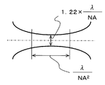
- the light of the objective lens 304 has a depth of focus ⁇ / NA 2 that is optically determined by the numerical aperture NA of the objective lens 304 and the wavelength ⁇ of the light emitted from the light-emitting element, and the light diameter 1. It has 22 ⁇ ⁇ / NA. Therefore, as the distance from the focal position of the objective lens 304 increases, the diameter of the light increases and the resolution of the measuring device decreases.
- the depth of focus is 63 ⁇ m and the light (beam) diameter is 7.7 ⁇ m.
- one or more spherical or aspherical lenses are used as the objective lens 304, and the depth of measurement and the resolution of measurement are determined by the numerical aperture NA of the objective lens 304. ing. Specifically, in order to increase the measurement depth, it is necessary to decrease the numerical aperture NA of the objective lens 304. However, if the numerical aperture NA is decreased, the resolution of the measurement is deteriorated. On the other hand, in order to increase the measurement resolution, it is necessary to increase the numerical aperture NA of the objective lens 304. However, increasing the numerical aperture NA decreases the depth of measurement. As described above, when one or more spherical or aspherical lenses are used as the objective lens 304, in the apparatus using the Michelson interference, the measurement depth and the measurement high resolution are in an incompatible relationship. Can not be compatible.
- an object of the present invention is to provide a shape measuring apparatus and method capable of solving both of the above-described problems and achieving both a large depth of measurement and a high resolution of measurement.
- the present invention is configured as follows.
- a light source that emits parallel light
- a beam splitter that branches the parallel light emitted from the light source into two lights, and one of the two lights that are branched by the beam splitter.
- One light is transmitted, and the transmitted light is changed to light having a maximum energy density on the optical axis over a distance ⁇ that satisfies the following formula, and is irradiated on the surface of the object to be measured.
- a detector that detects interference light between the reflected light or backscattered light that has been irradiated and transmitted through the conical lens and reflected light from the reference mirror, and the interference light detected based on the interference light detected by the detector.
- the measurement object Shape measuring apparatus characterized by comprising a shape measuring unit for measuring the shape of the surface.
- ⁇ / 2 sin ⁇ 1 ⁇ nsin ( ⁇ / 2 ⁇ / 2) ⁇ ⁇ ⁇ / 2 + ⁇ / 2
- D Effective diameter of the conical lens
- ⁇ Conical apex angle of the conical lens
- ⁇ Distance along the optical axis of the light from the apex of the conical lens to the object to be measured
- n Refractive index of the conical lens
- the shape measuring apparatus according to the first aspect, further comprising an optical filter that is disposed between the beam splitter and the conical lens and shields a region corresponding to the top of the conical lens. I will provide a.
- the apparatus further includes a plurality of shutters disposed between the beam splitter and the conical lens, each having a shielding part and a donut-shaped transmission part arranged on an outer periphery of the shielding part.
- the shielding portions of the plurality of shutters shield regions corresponding to the tops of the conical lenses, and the positions of the transmission portions of the plurality of shutters are arranged at different positions, and the shape measuring unit is And a measurement unit that selectively uses the plurality of shutters to selectively irradiate the light from the conical lens onto the surfaces of the plurality of objects to be measured, and performs the shape measurement.
- a shape measuring apparatus is provided.
- the shape of the surface of the object to be measured is obtained by moving the object to be measured in a direction orthogonal to the optical axis direction of the light incident on the object to be measured from the conical lens.
- the shape measuring device according to any one of the first to third aspects, further comprising a device to be measured moving device for measuring the above.
- the parallel light emitted from the light source is branched into two lights, and one of the branched two lights is set to a distance ⁇ that satisfies the following formula using a conical lens. Then, the energy density on the optical axis is changed to light that is maximized, the surface of the object to be measured is irradiated, the other of the two light beams branched off is reflected by a reference mirror, and the object to be measured is Interference light between reflected light or backscattered light reflected by the surface and transmitted through the conical lens and reflected light from the reference mirror is detected, and based on the detected interference light, the object to be measured is detected.
- a shape measuring method comprising measuring the shape of the surface.
- ⁇ / 2 sin ⁇ 1 ⁇ nsin ( ⁇ / 2 ⁇ / 2) ⁇ ⁇ ⁇ / 2 + ⁇ / 2
- D Effective diameter of the conical lens
- ⁇ Conical apex angle of the conical lens
- ⁇ Distance along the optical axis of the light from the apex of the conical lens to the object to be measured
- n Refractive index of the conical lens
- the shutter disposed between the beam splitter and the conical lens when the one light out of the two lights branched by the beam splitter passes through the conical lens. Based on the first reflected light reflected by the first surface of the object to be measured, the one light transmitted through the doughnut-shaped transmission part arranged on the outer periphery of the region corresponding to the top of the conical lens After measuring the shape of the first surface of the object to be measured, when the one light out of the two lights branched by the beam splitter passes through the conical lens, a transmission portion is provided at a position different from the shutter.
- the other shutter having the other shutter disposed between the beam splitter and the conical lens and disposed on an outer periphery of a region corresponding to a top of the conical lens of the another shutter
- the second surface of the second object different from the first surface of the object to be measured is based on the second reflected light that is reflected by the second surface of the object to be measured.
- the device under test is moved by the device under test moving device in a direction perpendicular to the optical axis direction of the light incident on the device under test from the conical lens, and the device under test is measured.
- the shape measuring method according to the fifth or sixth aspect wherein the shape of the surface of an object is measured.
- shape measurement capable of measuring at a greater depth for example, having a depth of focus one or two orders of magnitude greater than conventional
- high resolution for example, having sub-micron resolution or less
- FIG. 1 is a diagram of a basic configuration of a shape measuring apparatus according to a first embodiment of the present invention.
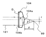
- FIG. 2 is a diagram for explaining the operation of the conical lens of the shape measuring apparatus according to the first embodiment.
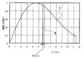
- FIG. 3 is a graph comparing the distance ⁇ and the light energy density I between the case of the conical lens of the first embodiment of the present invention and the case of the conventional objective lens.
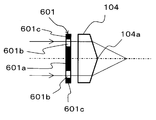
- FIG. 4A is a cross-sectional view illustrating the operation of the optical filter of the shape measuring apparatus according to the second embodiment of the present invention.
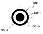
- FIG. 4B is a plan view of the optical filter of the shape measuring apparatus according to the second embodiment of the present invention.
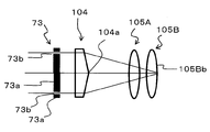
- FIG. 5A is a diagram showing one specific configuration example of the shape measuring apparatus according to the first embodiment
- FIG. 5B is an explanatory diagram when inspecting the shapes of the front and back surfaces of a plurality of lenses using the shape measuring apparatus according to the first embodiment
- FIG. 5C is an explanatory diagram showing a partial configuration of the shape measuring apparatus according to the third embodiment of the present invention
- FIG. 5D is an explanatory diagram showing a partial configuration of the shape measuring apparatus according to the third embodiment
- FIG. 5E is an explanatory diagram showing a partial configuration of the shape measuring apparatus according to the third embodiment
- FIG. 5A is a diagram showing one specific configuration example of the shape measuring apparatus according to the first embodiment
- FIG. 5B is an explanatory diagram when inspecting the shapes of the front and back surfaces of a plurality of lenses using the shape measuring apparatus according to the first embodiment
- FIG. 5C is an explanatory
- FIG. 5F is an explanatory diagram showing a partial configuration of the shape measuring apparatus according to the third embodiment
- FIG. 5G is an explanatory diagram showing a partial configuration of the shape measuring apparatus according to the third embodiment
- FIG. 5H is a flowchart showing a procedure when a shape measuring operation is performed using the shape measuring apparatus according to the third embodiment
- FIG. 5I is an explanatory diagram of a lens to be tested when performing a shape measurement operation using the shape measurement apparatus according to the third embodiment
- FIG. 6 is a diagram of the configuration of a conventional shape measuring apparatus
- FIG. 7 is a diagram for explaining the problems of the conventional shape measuring apparatus.
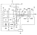
- FIG. 1 shows a basic configuration of a shape measuring apparatus 83 according to the first embodiment of the present invention.
- reference numeral 101 denotes a light emitting element that emits light
- 102 denotes a collimator lens that changes the light emitted from the light emitting element 101 to parallel light 120.
- the light emitting element 101 and the collimator lens 102 constitute a parallel light source 90.
- Reference numeral 103 denotes a beam splitter for branching the parallel light 120 from the collimator lens 102 into two parts, that is, the measured object side and the reference mirror side.
- Reference numeral 104 denotes an emission side (measurement target) for irradiating the measurement target 105 with the first parallel light 121A, which is one of the parallel lights branched to the measurement target side by the beam splitter 103.
- the object 105 side) is a conical lens having a conical shape. That is, the conical lens 104 here means a lens having a conical shape at least on the emission side.
- the incident side (beam splitter 103 side) of the conical lens 104 with respect to the first parallel light 121A may be a flat surface or a curved surface.
- the 106 is a lens that condenses the second parallel light 121B, which is another parallel light branched by the beam splitter 103, and 107 is a reference reflection mirror that reflects the second parallel light 121B.
- the reference reflecting mirror 107 can be moved back and forth in the optical axis direction of the second parallel light 121B by a reflecting mirror moving device 91 as an example of a reference plane driving unit.
- the reflecting mirror moving device 91 can drive the reference reflecting mirror 107 functioning as a reference plane in the vertical direction of FIG.
- Reference numeral 108 denotes a lens that collects interference light of two lights 123 and 124, that is, reflected light or scattered light 123 from an object 105 to be measured such as an industrial product and reflected light 124 from a reference reflecting mirror 107.
- Reference numeral 109 denotes a detector (for example, a photodetector) that is an element for detecting the condensed interference light.
- the shape inspection apparatus 82 is configured by the above-described components excluding the DUT 105. Further, a part obtained by removing the movable stage from the shape inspection apparatus 82 is a shape inspection unit 81. By moving the shape inspection unit 81 relative to the object 105, the surface of the object 105 to be measured can be inspected.
- a shape measuring unit 80 that measures the shape of the surface of the object 105 to be measured based on the interference light detected by the detector 109 is connected to the detector 109 to form the shape measuring device 83 as a whole. is doing.
- the shape measuring unit 80 may be configured by known software that can measure the shape of the surface of the DUT 105 based on the interference light detected by the detector 109.
- a spectroscope 80A, an A / D converter 80B, and a personal computer 80C are used, and the interference light detected by the detector 109 is used. Only the necessary light is extracted by performing spectroscopy with the spectroscope 80A. After the analog information contained in the light extracted by the spectroscope 80A is converted to digital information by the A / D converter 80B, the shape information may be obtained by using known software built in the personal computer 80C.
- the light emitting element 101, the collimator lens 102, the beam splitter 103, the conical lens 104, and the device under test 105 are arranged on the same optical axis.
- the lens 106 and the reference reflection mirror 107 are arranged coaxially with respect to the lens 108 and the detector 109 along a direction orthogonal to the optical axis of the light emitting element 101 and with the beam splitter 103 interposed therebetween. .
- the device under test 105 is a movable stage 92 as an example of a device under test moving device configured by an X-axis stage 92x on which the device under test 105 is held and a Y-axis stage 92y that movably supports the X-axis stage 92x. Thus, each is moved in the XY directions.
- the X-axis stage 92x is a mechanism that drives the DUT 105 in the X-axis direction (a direction that penetrates the paper surface of FIG. 1).
- the Y-axis stage 92y is a mechanism that drives the DUT 105 in the Y-axis direction (vertical direction in FIG.
- the X-axis stage 92x and the Y-axis stage 92y are used to be placed on a placement portion (not shown) on the X-axis stage 92x.
- the measured object 105 is moved relative to the shape inspection unit 81 so that the entire surface of the measured object 105 to be measured can be inspected.
- FIG. 1A in order to facilitate understanding, the forward and backward paths of light traveling along the optical axis are shown with their positions slightly shifted from each other.
- the light emitted from the light emitting element 101 becomes parallel light 120 by the collimating lens 102.
- the parallel light 120 is split into two parallel lights 121A and 121B by the beam splitter 103.
- the first parallel light 121 ⁇ / b> A from the beam splitter 103 is incident on the flat bottom surface 104 b of the conical lens 104 with a refractive index n having a conical shape with an apex angle ⁇ [°].
- the first parallel light 121A incident on the conical lens 104 is refracted with an angle ( ⁇ / 2) [°] formed with the optical axis expressed by the following equation (2).
- the light energy density of the first parallel light 121A that exits from the collimator lens 102 and enters the conical lens 104 via the beam splitter 103 is i, and an arbitrary point (for example, an object to be measured) 89 from the apex 104a of the conical lens 104.
- the distance along the optical axis of the first parallel light 121A up to ⁇ [mm] (where 0 ⁇ ), and the distance between the optical axis of the first parallel light 121A and the optical axis of the conical lens 104 is r [mm].
- the beam profile is a 1 / r curve, and the light energy density I is maximized on the optical axis.
- Such a point 89 at a distance ⁇ where the light energy density I is high can be expressed as Expression (4), where the effective diameter of the conical lens 104 is D [mm].
- ⁇ [nm] is the wavelength of light (beam) emitted from the light source.
- the conical lens 104 is formed in a shape that satisfies the above-described formula.
- the light (beam) 122 transmitted through the conical lens 104 is irradiated on the surface of the object 105 to be measured.
- the reflected light from the surface of the object 105 to be measured or the backscattered light 123 on the surface of the object 105 to be transmitted is transmitted through the conical lens 104 and the beam splitter.
- the second parallel light 121 ⁇ / b> B that is emitted from the collimator lens 102 and enters the reference reflection mirror 107 via the beam splitter 103 and further via the condenser lens 106 is reflected by the reference reflection mirror 107. .
- the reflected light 124 reflected by the reference reflecting mirror 107 enters the beam splitter 103 via the condenser lens 106.
- the reflected light or backscattered light 123 on the surface of the object 105 to be measured and the reflected light 124 from the reference mirror 107 are combined again by the beam splitter 103 to become interference light, and the interference light passes through the condenser lens 108. Enters the detector 109 and the detector 109 detects the interference light.
- FIG. 3 shows a graph (see arrow I) in which the distance ⁇ at the conical lens 104 and the intensity I of light (beam) are normalized by the maximum intensity value.
- the horizontal axis is the distance ⁇
- the vertical axis is the intensity I of light (beam).
- a graph in which the distance ⁇ and the intensity I of light (beam) are normalized by the maximum value of the intensity is also shown in FIG.
- the point of the distance ⁇ where the light energy density I is high extends over 11.4 mm.
- the diameter ⁇ of the light (beam) spot at the point of the distance ⁇ where the light energy density I is high it is 1.5 ⁇ m.
- NA 0.1
- the depth of focus was only 63 ⁇ m (see FIG. 3).
- the light (beam) diameter can be obtained.
- the intensity of the interference light between the reflected light from the object to be measured 105 or the backscattered light and the reflected light from the reference mirror 107 is detected by the detector 109 with finer horizontal resolution. Then, the shape can be measured by the shape measuring unit 80. Therefore, in the shape measuring apparatus 83 according to the present embodiment, since the depth of focus is deep, the thickness direction of the object to be measured 105 (direction orthogonal to the XY direction) can be obtained only by moving in the XY direction along the surface of the object to be measured 105. That is, the shape measurement in the depth direction) can be almost performed, and the shape measurement can be performed almost without moving the object 105 to be measured in the depth direction.
- the light emitting element 101, the movable stage 92, the reflecting mirror moving device 91, the detector 109, and the shape measuring unit 80 are connected to the control device 60, respectively.
- the shape measurement operation is performed under the respective control.
- the reference mirror 107 In measuring the shape, the reference mirror 107 is fixed and the object to be measured 105 is moved in the X direction, the Y direction, or the XY direction by the movable stage 92, and the interference light of the reflected light or scattered light is detected by the detector 109. May be. Conversely, the object to be measured 105 may be fixed, and the interference light of reflected light or scattered light may be detected by the detector 109 while the reference mirror 107 is moved by the reflection mirror moving device 91.
- the shape measuring device 83 By measuring the shape of the object 105 to be measured using the light (irradiation beam) as described above, it is possible to realize the shape measuring device 83 capable of measuring at a large depth and with high resolution.
- (Second Embodiment) 4A and 4B show a partial configuration of the shape measuring apparatus according to the second embodiment of the present invention.
- an optical filter 601 is disposed in front of the conical lens 104 (on the light emitting element 101 side).
- the optical filter 601 for example, a concentric light transmission part 601b (the white part in FIGS. 4A and 4B) and a mask part (shielding part) 601a (shielded part) arranged in a region other than the transmission part 601b to shield light. What formed the black part of FIG. 4A and FIG. 4B can be used.
- the mask portion 601a shields light (beam) disturbed near the apex because the shape accuracy near the apex is not sufficient. Can be lost.
- the minimum range of the mask portion 601a for removing processing errors is a range of 1 ⁇ m in diameter.
- the outer peripheral mask portion 601c is optional and may be omitted.
- the shape is not an acute angle and the shape is within the range of about 10 ⁇ m in the vicinity of the apex. May be. Therefore, by masking a region having a diameter of 2 mm or more around the apex to form the mask portion 601a and shielding the light with the mask portion 601a, the region of light (beam) disturbed by a processing error can be eliminated.
- the shape measurement procedure in the second embodiment is the same as that in the first embodiment.
- the reflected light or backscattered light from the object 105 to be measured passes through the optical filter 601 in the opposite optical path coaxial with the incident light and is detected by the detector 109.
- the reference mirror 107 is fixed, and the object 105 to be measured is moved in the X direction, the Y direction, or the XY direction by the movable stage 92 while reflecting light or
- the interference light of the scattered light may be detected by the detector 109.
- FIG. 5A shows one specific configuration example of the shape measuring apparatus according to the first embodiment described above.
- FIG. 5B is an explanatory diagram for inspecting the shapes of the front and back surfaces of a plurality of lenses using the shape measuring apparatus according to the first embodiment described above.
- FIGS. 5C to 5G respectively show a partial configuration of the shape measuring apparatus according to the third embodiment of the present invention.
- FIG. 5H is a flowchart showing a procedure when a shape measuring operation is performed using the shape measuring apparatus according to the first embodiment described above.
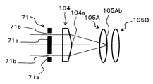
- the measurement object 105 that is a measurement object (test lens)
- a plurality of tests such as a lens barrel of a digital still camera (DSC) are used.
- a lens provided with the lenses 105A and 105B coaxially is defined as a measurement object (test lens).
- the lens barrel itself is omitted, and only the plurality of test lenses 105A and 105B are illustrated.
- Shapes of the front and back surfaces of the plurality of test lenses 105A and 105B as such measurement objects (the front surface 105Aa and the back surface 105Ab of the first test lens 105A and the front surface 105Ba and the back surface 105Bb of the second test lens 105B).
- 5B in the state assembled as a lens barrel, the front and back surfaces of the test lenses 105A and 105B (the front surface 105Aa and the back surface 105Ab of the first test lens 105A, and the second test sample).
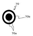
- a plurality of donut-shaped shutters 70, 71, 72, 73 having different diameters are prepared, and the plurality of shutters 70 are as shown in FIGS. 5C to 5G. , 71, 72, 73 are adjusted so that the front and back surfaces of the DUT 105 are focused as shown in FIG. 5B.
- the first shutter 70 forms a concentric light transmitting portion 70b in a region corresponding to the vicinity of the periphery of the top of the conical lens 104, and the remaining portion ( A mask part (shielding part) 70a is formed on the top part and the outer peripheral part of the transmission part 70b.
- the light transmitted through the transmission part 70b is focused on the surface 105Aa of the first lens 105A by the conical lens 104, reflected by the surface 105Aa, and then transmitted through the transmission part 70b again.
- the shape of the surface 105Aa can be detected by moving toward the beam splitter 103.
- the area of the transmission part 70b and the area of the mask part 70a on the center side are set to be approximately the same.
- the second shutter 71 has a concentric light transmission part 71b on the outer peripheral side from the position of the transmission part 70b, that is, between the top part and the outer peripheral part of the conical lens 104.
- the mask portion 71a is formed in the remaining portion (the portion on the optical axis center side of the transmission portion 71b and the outer peripheral portion of the transmission portion 71b).
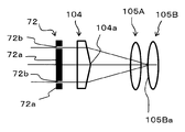
- the third shutter 72 forms a concentric light transmitting portion 72b at a position closer to the outer peripheral side than the position of the transmitting portion 71b, and the remaining portion (light of the transmitting portion 72b).
- a mask portion 72a is formed on the axial center portion and the outer peripheral portion of the transmission portion 72b.
- the fourth shutter 73 forms a concentric light transmitting portion 73b at a position closer to the outer peripheral side than the position of the transmitting portion 72b, and the remaining portion (light of the transmitting portion 73b).
- a mask portion 73a is formed on the axial center portion and the outer peripheral portion of the transmission portion 73b.
- transmission part 73b will permeate
- the tables of the test lenses 105A, 105B are moved without moving the optical system such as the conical lens 104. Focus on the back side.
- a plurality of shutters in this way, when measuring the shape of the front surface 105Aa and the back surface 105A of the first lens, that is, the first lens 105A, the second and subsequent lenses, It is possible to remove the light whose focal depth matches the front surface 105Ba and the back surface 105Bb of the second test lens 105B, and to prevent interference with the second and subsequent test lenses.
- the shape of the test lens can be accurately measured.
- the shielding portion in the vicinity of the top of each of the first to fourth shutters 70, 71, 72, and 73 is omitted, and the entire area in the vicinity of the top is regarded as the transmission portion. You can also
- the switching device 61 for the first to fourth shutters 70, 71, 72, 73 fixes the first to fourth shutters 70, 71, 72, 73 to a disk member, and rotates the motor or the like.
- the disk member is rotated by a predetermined angle by the apparatus, and a desired shutter of the first to fourth shutters 70, 71, 72, 73 is positioned on the optical axis, and any one of the states shown in FIGS. 5C to 5G It is possible to control so that Such control of the shutter switching operation can be performed by the control device 60 that controls the operation of the entire shape measuring apparatus.
- the control device 60 controls the operations of the light emitting element 101, the movable stage 92, the reflection mirror moving device 91, the detector 109, the shape measuring unit 80, and the switching device 61, respectively.
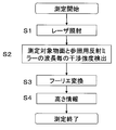
- the shape measuring operation by the shape measuring device 83 will be described with reference to FIG. 5H. This shape measurement operation is performed under operation control by the control device 60.
- step S1 the surface of the object to be measured 105 is irradiated with laser through the light emitting element 101 through the collimator lens 102, the beam splitter 103, and the conical lens 104.
- step S ⁇ b> 2 the reflected light reflected from the surface of the object 105 to be measured or the backscattered light scattered behind the surface passes through the conical lens 104, and is reflected by the reference mirror 107 and the beam splitter 103.
- the combined light becomes interference light, and the interference light is detected by the detector 109 via the condenser lens 108. That is, the detector 109 detects the interference intensity for each wavelength of the surface of the object 105 to be measured and the reference reflecting mirror 107.
- step S3 the interference intensity detected by the spectroscope 80A of the shape measuring unit 80 via the detector 109 is converted into digital information by the A / D converter 80B, and then taken into the personal computer 80C. Fourier transform the information.
- step S4 the measurement of the shape of the surface of the object to be measured 105 is completed by obtaining the height information from the digital information obtained by Fourier transforming the digital information in step S3.
- Steps S1 to S4 are performed for each of the first to fourth shutters 70, 71, 72, and 73 by driving the switching device 61, whereby the front and back surfaces of the plurality of lenses 105A and 105B (the first lens 105A).
- the shape of the front surface 105Aa and the back surface 105Ab and the front surface 105Ba and the back surface 105Bb) of the second lens 105B can be inspected.
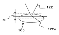
- the object to be measured 105 is either a spherical surface or an aspherical surface. It is necessary to move the optical system such as the conical lens 104 so as to trace the surface shape of the lens.
- the focal point 122a is set near the center of the surface of the object to be measured 105 in the optical axis depth direction as shown in FIG.
- the inspection can be performed without moving the conical lens 104 or the like at all. This is because the inspection is performed without moving the conical lens 104 or the like by performing the Fourier transform by detecting with the spectroscope 80A, or by performing the inspection by moving the conical lens 104 or the reference mirror 107, and optically. Because they are equivalent.
- the parallel light 120 emitted from the parallel light source 90 is branched into two parallel lights 121A and 121B by the beam splitter 103, and one parallel light 121A of the branched light is converted into a cone.
- the lens 104 irradiates the surface of the object 105 to be measured by changing to the light (beam) 122 that maximizes the energy density I on the optical axis over the distance ⁇ satisfying the equations (4) and (2).
- the other parallel light 121 ⁇ / b> B of the obtained light is irradiated on the reference mirror 107, reflected light or backscattered light 123 of the light (beam) 122 irradiated on the surface of the object 105 to be measured, and reflected light 124 from the reference mirror 107.
- Is detected by the detector 109, and the shape of the surface of the DUT 105 is measured by the shape measuring unit 80 based on the interference light detected by the detector 109. Because of such a configuration, it is possible to perform shape measurement with a depth (for example, one or two orders of magnitude greater than the conventional depth) and high resolution (for example, a resolution of submicron or less). it can.
- the depth of measurement and the resolution of measurement are determined by the numerical aperture NA of the objective lens, and deep measurement is performed.
- the depth of measurement and the high resolution of measurement are in conflict with each other, making it impossible to achieve both.
- the conical lens 104 having a configuration satisfying the above equations (4) and (2) a depth larger than the conventional one (for example, one digit or more than the conventional one) It is possible to perform shape measurement with a double-digit greater depth of focus and high resolution (for example, sub-micron resolution).
- the shape measurement for measuring the shape of the surface or the back surface of an object to be measured such as an industrial product (for example, a lens) capable of measuring the shape of the object to be measured with a large depth and high resolution. It is useful as an apparatus and method.
Landscapes
- Physics & Mathematics (AREA)
- General Physics & Mathematics (AREA)
- Health & Medical Sciences (AREA)
- General Health & Medical Sciences (AREA)
- Nuclear Medicine, Radiotherapy & Molecular Imaging (AREA)
- Radiology & Medical Imaging (AREA)
- Length Measuring Devices By Optical Means (AREA)
- Instruments For Measurement Of Length By Optical Means (AREA)
Abstract
Description
図6において、201は光を出射する発光素子、202は発光素子201から出射された光を平行光にするコリメータレンズである。また、203は、コリメータレンズ202からの平行光を被測定物側と参照ミラー側に分岐するためのビームスプリッタである。304は、ビームスプリッタ203で分岐された平行光の1つを205の被測定物に照射するための対物レンズである。206、207は、ビームスプリッタ203で分岐された平行光のもう一つを集光するレンズと、参照用の反射ミラーとである。208、209は被測定物205からの反射光、又は散乱光と、参照用の反射ミラー207からの2つの光の干渉光を集光するレンズと、検出する素子である検出器とである。
本発明の第1態様によれば、平行光を出射する光源と、前記光源から出射した平行光を2つの光に分岐するビームスプリッタと、前記ビームスプリッタで分岐した前記2つの光のうちの1つの光が透過し、この透過する光を、下記数式を満たす距離ρに亘って光軸上のエネルギー密度が極大になる光に変えて、被測定物の表面に照射すると共に、前記被測定物の前記表面からの反射光又は後方散乱光が透過する円錐レンズと、前記ビームスプリッタで分岐した前記2つの光のうちのもう一方の光を反射する参照ミラーと、前記被測定物の前記表面に照射しかつ前記円錐レンズを透過した前記反射光又は後方散乱光と、前記参照ミラーからの反射光との干渉光を検出する検出器と、前記検出器で検出された前記干渉光を基に前記被測定物の前記表面の形状を測定する形状測定部と、を備えていることを特徴とする形状測定装置。
ρ<D/{2tan(β)}
ただし、β/2=sin-1{nsin(π/2-α/2)}-π/2+α/2
D:前記円錐レンズの有効径
α:前記円錐レンズの円錐形状の頂角
ρ:前記円錐レンズの頂点から前記被測定物までの前記光の光軸に沿った距離
n:前記円錐レンズの屈折率
ρ<D/{2tan(β)}
ただし、β/2=sin-1{nsin(π/2-α/2)}-π/2+α/2
D:前記円錐レンズの有効径
α:前記円錐レンズの円錐形状の頂角
ρ:前記円錐レンズの頂点から前記被測定物までの前記光の光軸に沿った距離
n:前記円錐レンズの屈折率
図1は、本発明の第1実施形態に係る形状測定装置83の基本構成を示している。
図1において、101は光を出射する発光素子、102は発光素子101から出射された光を平行光120にするコリメータレンズであり、発光素子101とコリメータレンズ102とで平行光光源90を構成している。また、103は、コリメータレンズ102からの平行光120を被測定物側と参照ミラー側との2つに分岐するためのビームスプリッタである。104は、ビームスプリッタ103で被測定物側に分岐された平行光の1つである第1平行光121Aを被測定物105に照射するための、被測定物105と対向する出射側(被測定物105側)が円錐形状となった円錐レンズである。すなわち、ここで言う円錐レンズ104とは、少なくとも、出射側の形状が円錐形状となったレンズを意味する。円錐レンズ104の第1平行光121Aに対する入射側(ビームスプリッタ103側)は、平面又は湾曲面でもよい。
コリメータレンズ102から出射してビームスプリッタ103を介して円錐レンズ104に入射する第1平行光121Aの光エネルギー密度をiとし、円錐レンズ104の頂点104aから任意の点(例えば、被測定物)89までの第1平行光121Aの光軸に沿った距離をρ[mm](ただし、0<ρ)、且つ第1平行光121Aの光軸と円錐レンズ104の光軸と距離をr[mm](ただし、0≦r≦(D/2))とすると、頂点104aから任意の点(例えば、被測定物)89までの距離ρ、第1平行光121Aの光軸と円錐レンズ104の光軸との距離rの点89における光エネルギー密度I(ρ,r)は、以下の式(3)のようになる。

式(3)のように、ビームプロファイルは1/rの曲線となり、光エネルギー密度Iは光軸上で極大となる。このような光エネルギー密度Iが高い距離ρの点89は、円錐レンズ104の有効径をD[mm]とすると、式(4)のように表せる。
また、光エネルギー密度Iが高い距離ρの点89での光(ビーム)スポットの直径をφ[μm]とすると、式(5)のように表せる。λ[nm]は光源から出射される光(ビーム)の波長である。
円錐レンズ104は、前記したような式が成立するような形状で構成する。
図4A及び図4Bは本発明の第2実施形態にかかる形状測定装置の一部の構成を示している。
図5Aは、前述の第1実施形態に係る形状測定装置の1つの具体的な構成例を示している。図5Bは、前述の第1実施形態に係る形状測定装置を使用して、複数のレンズの表裏面の形状を検査する場合の説明図である。図5A及び図5Bでは、理解しやすくするため、光軸中心を進む光の往路と復路とを少し位置をずらせて示すようにしている。図5C~図5Gは本発明の第3実施形態にかかる形状測定装置の一部の構成をそれぞれ示している。図5Hは、前述の第1実施形態に係る形状測定装置を使用して形状測定動作を行なうときの手順を示すフローチャートである。
Claims (7)
- 平行光を出射する光源と、
前記光源から出射した平行光を2つの光に分岐するビームスプリッタと、
前記ビームスプリッタで分岐した前記2つの光のうちの1つの光が透過し、この透過する光を、下記数式を満たす距離ρに亘って光軸上のエネルギー密度が極大になる光に変えて、被測定物の表面に照射すると共に、前記被測定物の前記表面からの反射光又は後方散乱光が透過する円錐レンズと、
前記ビームスプリッタで分岐した前記2つの光のうちのもう一方の光を反射する参照ミラーと、
前記被測定物の前記表面に照射しかつ前記円錐レンズを透過した前記反射光又は後方散乱光と、前記参照ミラーからの反射光との干渉光を検出する検出器と、
前記検出器で検出された前記干渉光を基に前記被測定物の前記表面の形状を測定する形状測定部と、を備えている形状測定装置。
ρ<D/{2tan(β)}
ただし、β/2=sin-1{nsin(π/2-α/2)}-π/2+α/2
D:前記円錐レンズの有効径
α:前記円錐レンズの円錐形状の頂角
ρ:前記円錐レンズの頂点から前記被測定物までの前記光の光軸に沿った距離
n:前記円錐レンズの屈折率 - 前記ビームスプリッタと前記円錐レンズとの間に配置され、前記円錐レンズの頂部に対応する領域を遮蔽する光学フィルタをさらに備える請求項1に記載の形状測定装置。
- 前記ビームスプリッタと前記円錐レンズとの間に配置され、遮蔽部と前記遮蔽部の外周に配置されたドーナツ状の透過部とを有するシャッターを複数個さらに備え、
前記複数個のシャッターの前記遮蔽部は前記円錐レンズの頂部に対応する領域を遮蔽し、
前記複数個のシャッターの前記透過部のそれぞれの位置は互いに異なる位置に配置され、
前記形状測定部は、前記複数個のシャッターを選択的に使用して、複数の前記被測定物の表面それぞれに対して前記円錐レンズからの前記光を選択的に照射して前記形状測定を行う測定部である、請求項1に記載の形状測定装置。 - 前記円錐レンズから前記被測定物に入射する前記光の光軸方向と直交する方向に前記被測定物を移動させて、前記被測定物の前記表面の形状を測定する被測定物移動装置をさらに備える、請求項1~3のいずれか1つに記載の形状測定装置。
- 光源から出射された平行光を2つの光に分岐させ、
分岐された前記2つの光のうちの1つの光を、円錐レンズにより下記数式を満たす距離ρに亘って光軸上のエネルギー密度が極大になる光に変えて、被測定物の表面に照射させ、
分岐した前記2つの光のうちのもう一方の光を参照ミラーで反射させ、
前記被測定物の前記表面で反射し且つ前記円錐レンズを透過した反射光又は後方散乱光と、前記参照ミラーからの反射光との干渉光を検出し、
検出された前記干渉光を基に前記被測定物の前記表面の形状を測定する形状測定方法。
ρ<D/{2tan(β)}
ただし、β/2=sin-1{nsin(π/2-α/2)}-π/2+α/2
D:前記円錐レンズの有効径
α:前記円錐レンズの円錐形状の頂角
ρ:前記円錐レンズの頂点から前記被測定物までの前記光の光軸に沿った距離
n:前記円錐レンズの屈折率 - ビームスプリッタで分岐した前記2つの光のうちの前記1つの光が前記円錐レンズを透過する時、前記ビームスプリッタと前記円錐レンズとの間に配置されたシャッターの前記円錐レンズの頂部に対応する領域の外周に配置されたドーナツ状の透過部を透過した前記1つの光が前記被測定物の第1表面で反射した第1反射光に基づいて、前記被測定物の第1表面の形状測定を行った後、
前記ビームスプリッタで分岐した前記2つの光のうちの前記1つの光が前記円錐レンズを透過する時、前記シャッターとは異なる位置に透過部を有する別のシャッターを前記ビームスプリッタと前記円錐レンズとの間に配置し、前記別のシャッターの前記円錐レンズの頂部に対応する領域の外周に配置された前記別のシャッターのドーナツ状の透過部を透過した前記1つの光が前記被測定物の第2表面で反射した第2反射光に基づいて、前記被測定物の前記第1表面とは異なる前記第2表面の形状測定を行う、請求項5に記載の形状測定方法。 - 前記円錐レンズから前記被測定物に入射する前記光の光軸方向と直交する方向に前記被測定物を被測定物移動装置により移動させて、前記被測定物の前記表面の形状を測定する、請求項5又は6に記載の形状測定方法。
Priority Applications (4)
| Application Number | Priority Date | Filing Date | Title |
|---|---|---|---|
| KR1020107020251A KR101233941B1 (ko) | 2009-03-19 | 2010-03-09 | 형상 측정 장치 및 방법 |
| US12/935,300 US20110043822A1 (en) | 2009-03-19 | 2010-03-09 | Shape measuring apparatus and method thereof |
| CN201080001241.8A CN101970983B (zh) | 2009-03-19 | 2010-03-09 | 形状测定装置以及方法 |
| EP10753255A EP2410289A1 (en) | 2009-03-19 | 2010-03-09 | Shape measurement device and method |
Applications Claiming Priority (2)
| Application Number | Priority Date | Filing Date | Title |
|---|---|---|---|
| JP2009067183A JP2010217124A (ja) | 2009-03-19 | 2009-03-19 | 形状測定装置及び方法 |
| JP2009-067183 | 2009-03-19 |
Publications (1)
| Publication Number | Publication Date |
|---|---|
| WO2010106758A1 true WO2010106758A1 (ja) | 2010-09-23 |
Family
ID=42739426
Family Applications (1)
| Application Number | Title | Priority Date | Filing Date |
|---|---|---|---|
| PCT/JP2010/001643 WO2010106758A1 (ja) | 2009-03-19 | 2010-03-09 | 形状測定装置及び方法 |
Country Status (6)
| Country | Link |
|---|---|
| US (1) | US20110043822A1 (ja) |
| EP (1) | EP2410289A1 (ja) |
| JP (1) | JP2010217124A (ja) |
| KR (1) | KR101233941B1 (ja) |
| CN (1) | CN101970983B (ja) |
| WO (1) | WO2010106758A1 (ja) |
Cited By (1)
| Publication number | Priority date | Publication date | Assignee | Title |
|---|---|---|---|---|
| CN116294983A (zh) * | 2023-02-28 | 2023-06-23 | 重庆米森科技有限公司 | 基于平面光路设计的非闭合光路波阵面分割干涉仪 |
Families Citing this family (6)
| Publication number | Priority date | Publication date | Assignee | Title |
|---|---|---|---|---|
| CN102581703A (zh) * | 2011-01-05 | 2012-07-18 | 财团法人精密机械研究发展中心 | 同轴向双进给轴量测装置 |
| US8810904B2 (en) * | 2011-02-09 | 2014-08-19 | Northwestern University | Optical contact micrometer |
| DE102011103003A1 (de) * | 2011-05-24 | 2012-11-29 | Lufthansa Technik Ag | Verfahren und Vorrichtung zur Rissprüfung eines Flugzeug- oder Gasturbinen-Bauteils |
| CN104949631B (zh) * | 2014-03-27 | 2017-12-15 | 纽富来科技股份有限公司 | 曲率测定装置以及曲率测定方法 |
| EP3290892B1 (en) * | 2016-08-30 | 2021-03-31 | Nidek Co., Ltd | Lens measurement device |
| CN106441152B (zh) * | 2016-10-18 | 2019-02-01 | 淮阴师范学院 | 非对称式光学干涉测量方法及装置 |
Citations (4)
| Publication number | Priority date | Publication date | Assignee | Title |
|---|---|---|---|---|
| JPH06341809A (ja) | 1993-06-01 | 1994-12-13 | Mitsutoyo Corp | マイケルソン形干渉測定装置 |
| JPH0763508A (ja) * | 1993-08-31 | 1995-03-10 | Ishikawajima Harima Heavy Ind Co Ltd | レーザ顕微鏡 |
| JPH08136248A (ja) * | 1994-11-08 | 1996-05-31 | Idec Izumi Corp | 共焦点位置測定装置 |
| JP3633713B2 (ja) * | 1996-04-23 | 2005-03-30 | 松下電器産業株式会社 | 距離計測方法及び距離センサ |
Family Cites Families (7)
| Publication number | Priority date | Publication date | Assignee | Title |
|---|---|---|---|---|
| US7072045B2 (en) * | 2002-01-16 | 2006-07-04 | The Regents Of The University Of California | High resolution optical coherence tomography with an improved depth range using an axicon lens |
| US7218403B2 (en) * | 2002-06-26 | 2007-05-15 | Zygo Corporation | Scanning interferometer for aspheric surfaces and wavefronts |
| JP4144389B2 (ja) * | 2003-03-14 | 2008-09-03 | オムロン株式会社 | 光学式膜計測装置 |
| CN2788123Y (zh) * | 2005-01-26 | 2006-06-14 | 闫宏 | 双光路自准直镀膜厚度光学监控装置 |
| US7586670B2 (en) * | 2006-05-13 | 2009-09-08 | Alcatel-Lucent Usa Inc. | Nonlinear optical devices based on metamaterials |
| CN101324422B (zh) * | 2007-06-12 | 2011-01-19 | 北京普瑞微纳科技有限公司 | 白光干涉测量样品表面形状精细分布的方法及其装置 |
| US20090195788A1 (en) * | 2007-12-17 | 2009-08-06 | Shinichi Dosaka | Apparatus for profile irregularity measurement and surface imperfection observation; method of profile irregularity measurement and surface imperfection observation; and inspection method of profile irregularity and surface imperfection |
-
2009
- 2009-03-19 JP JP2009067183A patent/JP2010217124A/ja not_active Withdrawn
-
2010
- 2010-03-09 WO PCT/JP2010/001643 patent/WO2010106758A1/ja active Application Filing
- 2010-03-09 US US12/935,300 patent/US20110043822A1/en not_active Abandoned
- 2010-03-09 CN CN201080001241.8A patent/CN101970983B/zh not_active Expired - Fee Related
- 2010-03-09 EP EP10753255A patent/EP2410289A1/en not_active Withdrawn
- 2010-03-09 KR KR1020107020251A patent/KR101233941B1/ko not_active IP Right Cessation
Patent Citations (4)
| Publication number | Priority date | Publication date | Assignee | Title |
|---|---|---|---|---|
| JPH06341809A (ja) | 1993-06-01 | 1994-12-13 | Mitsutoyo Corp | マイケルソン形干渉測定装置 |
| JPH0763508A (ja) * | 1993-08-31 | 1995-03-10 | Ishikawajima Harima Heavy Ind Co Ltd | レーザ顕微鏡 |
| JPH08136248A (ja) * | 1994-11-08 | 1996-05-31 | Idec Izumi Corp | 共焦点位置測定装置 |
| JP3633713B2 (ja) * | 1996-04-23 | 2005-03-30 | 松下電器産業株式会社 | 距離計測方法及び距離センサ |
Cited By (2)
| Publication number | Priority date | Publication date | Assignee | Title |
|---|---|---|---|---|
| CN116294983A (zh) * | 2023-02-28 | 2023-06-23 | 重庆米森科技有限公司 | 基于平面光路设计的非闭合光路波阵面分割干涉仪 |
| CN116294983B (zh) * | 2023-02-28 | 2024-01-23 | 重庆米森科技有限公司 | 基于平面光路设计的非闭合光路波阵面分割干涉仪 |
Also Published As
| Publication number | Publication date |
|---|---|
| JP2010217124A (ja) | 2010-09-30 |
| KR20100124757A (ko) | 2010-11-29 |
| EP2410289A1 (en) | 2012-01-25 |
| CN101970983B (zh) | 2012-08-29 |
| CN101970983A (zh) | 2011-02-09 |
| US20110043822A1 (en) | 2011-02-24 |
| KR101233941B1 (ko) | 2013-02-15 |
Similar Documents
| Publication | Publication Date | Title |
|---|---|---|
| JP6377218B2 (ja) | 計測システムおよび計測方法 | |
| WO2010106758A1 (ja) | 形状測定装置及び方法 | |
| TWI484139B (zh) | 彩色共焦掃描裝置 | |
| US7477401B2 (en) | Trench measurement system employing a chromatic confocal height sensor and a microscope | |
| JP4760564B2 (ja) | パターン形状の欠陥検出方法及び検出装置 | |
| US9671600B2 (en) | Light microscope and microscopy method | |
| EP2538170A1 (en) | Method and device for measuring multiple parameters of differential confocal interference component | |
| US10345246B2 (en) | Dark field wafer nano-defect inspection system with a singular beam | |
| CN104515469A (zh) | 用于检查微观样本的光显微镜和显微镜学方法 | |
| JP5268061B2 (ja) | 基板検査装置 | |
| US20240230551A9 (en) | Defect inspection device, defect inspection method, and adjustment substrate | |
| JP2002071513A (ja) | 液浸系顕微鏡対物レンズ用干渉計および液浸系顕微鏡対物レンズの評価方法 | |
| JP2010121960A (ja) | 測定装置及び被検物の測定方法 | |
| WO2012001929A1 (ja) | 波面収差測定装置及び波面収差測定方法 | |
| CN115291378A (zh) | 显微镜的光路系统 | |
| JP4325909B2 (ja) | 欠陥検査装置、欠陥検査方法、光学式走査装置、半導体デバイス製造方法 | |
| JP2008002891A (ja) | 表面状態検査装置及び表面状態検査方法 | |
| JP6143155B2 (ja) | フィラー微粒子分散性評価装置及びフィラー微粒子分散性評価方法 | |
| JP5759270B2 (ja) | 干渉計 | |
| KR101245097B1 (ko) | 박막 두께 측정장치 | |
| JP5046054B2 (ja) | 欠陥検査装置、欠陥検査方法、光学式走査装置、半導体デバイス製造方法 | |
| WO2021199340A1 (ja) | 欠陥検査装置及び欠陥検査方法 | |
| KR101326204B1 (ko) | 박막 두께 측정장치 및 방법 | |
| US8108942B2 (en) | Probe microscope | |
| JP2008261829A (ja) | 表面測定装置 |
Legal Events
| Date | Code | Title | Description |
|---|---|---|---|
| WWE | Wipo information: entry into national phase |
Ref document number: 201080001241.8 Country of ref document: CN |
|
| ENP | Entry into the national phase |
Ref document number: 20107020251 Country of ref document: KR Kind code of ref document: A |
|
| WWE | Wipo information: entry into national phase |
Ref document number: 12935300 Country of ref document: US |
|
| WWE | Wipo information: entry into national phase |
Ref document number: 2010753255 Country of ref document: EP |
|
| 121 | Ep: the epo has been informed by wipo that ep was designated in this application |
Ref document number: 10753255 Country of ref document: EP Kind code of ref document: A1 |
|
| NENP | Non-entry into the national phase |
Ref country code: DE |