WO2010090224A1 - 非水電解質二次電池、電池パック及び自動車 - Google Patents
非水電解質二次電池、電池パック及び自動車 Download PDFInfo
- Publication number
- WO2010090224A1 WO2010090224A1 PCT/JP2010/051518 JP2010051518W WO2010090224A1 WO 2010090224 A1 WO2010090224 A1 WO 2010090224A1 JP 2010051518 W JP2010051518 W JP 2010051518W WO 2010090224 A1 WO2010090224 A1 WO 2010090224A1
- Authority
- WO
- WIPO (PCT)
- Prior art keywords
- lithium
- negative electrode
- composite oxide
- oxide
- mass
- Prior art date
- Legal status (The legal status is an assumption and is not a legal conclusion. Google has not performed a legal analysis and makes no representation as to the accuracy of the status listed.)
- Ceased
Links
Images



Classifications
-
- H—ELECTRICITY
- H01—ELECTRIC ELEMENTS
- H01M—PROCESSES OR MEANS, e.g. BATTERIES, FOR THE DIRECT CONVERSION OF CHEMICAL ENERGY INTO ELECTRICAL ENERGY
- H01M4/00—Electrodes
- H01M4/02—Electrodes composed of, or comprising, active material
- H01M4/36—Selection of substances as active materials, active masses, active liquids
- H01M4/48—Selection of substances as active materials, active masses, active liquids of inorganic oxides or hydroxides
- H01M4/52—Selection of substances as active materials, active masses, active liquids of inorganic oxides or hydroxides of nickel, cobalt or iron
- H01M4/525—Selection of substances as active materials, active masses, active liquids of inorganic oxides or hydroxides of nickel, cobalt or iron of mixed oxides or hydroxides containing iron, cobalt or nickel for inserting or intercalating light metals, e.g. LiNiO2, LiCoO2 or LiCoOxFy
-
- H—ELECTRICITY
- H01—ELECTRIC ELEMENTS
- H01M—PROCESSES OR MEANS, e.g. BATTERIES, FOR THE DIRECT CONVERSION OF CHEMICAL ENERGY INTO ELECTRICAL ENERGY
- H01M10/00—Secondary cells; Manufacture thereof
- H01M10/05—Accumulators with non-aqueous electrolyte
- H01M10/052—Li-accumulators
- H01M10/0525—Rocking-chair batteries, i.e. batteries with lithium insertion or intercalation in both electrodes; Lithium-ion batteries
-
- H—ELECTRICITY
- H01—ELECTRIC ELEMENTS
- H01M—PROCESSES OR MEANS, e.g. BATTERIES, FOR THE DIRECT CONVERSION OF CHEMICAL ENERGY INTO ELECTRICAL ENERGY
- H01M10/00—Secondary cells; Manufacture thereof
- H01M10/05—Accumulators with non-aqueous electrolyte
- H01M10/056—Accumulators with non-aqueous electrolyte characterised by the materials used as electrolytes, e.g. mixed inorganic/organic electrolytes
- H01M10/0564—Accumulators with non-aqueous electrolyte characterised by the materials used as electrolytes, e.g. mixed inorganic/organic electrolytes the electrolyte being constituted of organic materials only
- H01M10/0566—Liquid materials
-
- H—ELECTRICITY
- H01—ELECTRIC ELEMENTS
- H01M—PROCESSES OR MEANS, e.g. BATTERIES, FOR THE DIRECT CONVERSION OF CHEMICAL ENERGY INTO ELECTRICAL ENERGY
- H01M10/00—Secondary cells; Manufacture thereof
- H01M10/05—Accumulators with non-aqueous electrolyte
- H01M10/056—Accumulators with non-aqueous electrolyte characterised by the materials used as electrolytes, e.g. mixed inorganic/organic electrolytes
- H01M10/0564—Accumulators with non-aqueous electrolyte characterised by the materials used as electrolytes, e.g. mixed inorganic/organic electrolytes the electrolyte being constituted of organic materials only
- H01M10/0566—Liquid materials
- H01M10/0568—Liquid materials characterised by the solutes
-
- H—ELECTRICITY
- H01—ELECTRIC ELEMENTS
- H01M—PROCESSES OR MEANS, e.g. BATTERIES, FOR THE DIRECT CONVERSION OF CHEMICAL ENERGY INTO ELECTRICAL ENERGY
- H01M4/00—Electrodes
- H01M4/02—Electrodes composed of, or comprising, active material
- H01M4/13—Electrodes for accumulators with non-aqueous electrolyte, e.g. for lithium-accumulators; Processes of manufacture thereof
- H01M4/131—Electrodes based on mixed oxides or hydroxides, or on mixtures of oxides or hydroxides, e.g. LiCoOx
-
- H—ELECTRICITY
- H01—ELECTRIC ELEMENTS
- H01M—PROCESSES OR MEANS, e.g. BATTERIES, FOR THE DIRECT CONVERSION OF CHEMICAL ENERGY INTO ELECTRICAL ENERGY
- H01M4/00—Electrodes
- H01M4/02—Electrodes composed of, or comprising, active material
- H01M4/13—Electrodes for accumulators with non-aqueous electrolyte, e.g. for lithium-accumulators; Processes of manufacture thereof
- H01M4/136—Electrodes based on inorganic compounds other than oxides or hydroxides, e.g. sulfides, selenides, tellurides, halogenides or LiCoFy
-
- H—ELECTRICITY
- H01—ELECTRIC ELEMENTS
- H01M—PROCESSES OR MEANS, e.g. BATTERIES, FOR THE DIRECT CONVERSION OF CHEMICAL ENERGY INTO ELECTRICAL ENERGY
- H01M4/00—Electrodes
- H01M4/02—Electrodes composed of, or comprising, active material
- H01M4/36—Selection of substances as active materials, active masses, active liquids
- H01M4/48—Selection of substances as active materials, active masses, active liquids of inorganic oxides or hydroxides
- H01M4/485—Selection of substances as active materials, active masses, active liquids of inorganic oxides or hydroxides of mixed oxides or hydroxides for inserting or intercalating light metals, e.g. LiTi2O4 or LiTi2OxFy
-
- H—ELECTRICITY
- H01—ELECTRIC ELEMENTS
- H01M—PROCESSES OR MEANS, e.g. BATTERIES, FOR THE DIRECT CONVERSION OF CHEMICAL ENERGY INTO ELECTRICAL ENERGY
- H01M4/00—Electrodes
- H01M4/02—Electrodes composed of, or comprising, active material
- H01M4/36—Selection of substances as active materials, active masses, active liquids
- H01M4/58—Selection of substances as active materials, active masses, active liquids of inorganic compounds other than oxides or hydroxides, e.g. sulfides, selenides, tellurides, halogenides or LiCoFy; of polyanionic structures, e.g. phosphates, silicates or borates
-
- H—ELECTRICITY
- H01—ELECTRIC ELEMENTS
- H01M—PROCESSES OR MEANS, e.g. BATTERIES, FOR THE DIRECT CONVERSION OF CHEMICAL ENERGY INTO ELECTRICAL ENERGY
- H01M4/00—Electrodes
- H01M4/02—Electrodes composed of, or comprising, active material
- H01M4/36—Selection of substances as active materials, active masses, active liquids
- H01M4/58—Selection of substances as active materials, active masses, active liquids of inorganic compounds other than oxides or hydroxides, e.g. sulfides, selenides, tellurides, halogenides or LiCoFy; of polyanionic structures, e.g. phosphates, silicates or borates
- H01M4/5825—Oxygenated metallic salts or polyanionic structures, e.g. borates, phosphates, silicates, olivines
-
- H—ELECTRICITY
- H01—ELECTRIC ELEMENTS
- H01M—PROCESSES OR MEANS, e.g. BATTERIES, FOR THE DIRECT CONVERSION OF CHEMICAL ENERGY INTO ELECTRICAL ENERGY
- H01M4/00—Electrodes
- H01M4/02—Electrodes composed of, or comprising, active material
- H01M4/62—Selection of inactive substances as ingredients for active masses, e.g. binders, fillers
- H01M4/624—Electric conductive fillers
- H01M4/625—Carbon or graphite
-
- Y—GENERAL TAGGING OF NEW TECHNOLOGICAL DEVELOPMENTS; GENERAL TAGGING OF CROSS-SECTIONAL TECHNOLOGIES SPANNING OVER SEVERAL SECTIONS OF THE IPC; TECHNICAL SUBJECTS COVERED BY FORMER USPC CROSS-REFERENCE ART COLLECTIONS [XRACs] AND DIGESTS
- Y02—TECHNOLOGIES OR APPLICATIONS FOR MITIGATION OR ADAPTATION AGAINST CLIMATE CHANGE
- Y02E—REDUCTION OF GREENHOUSE GAS [GHG] EMISSIONS, RELATED TO ENERGY GENERATION, TRANSMISSION OR DISTRIBUTION
- Y02E60/00—Enabling technologies; Technologies with a potential or indirect contribution to GHG emissions mitigation
- Y02E60/10—Energy storage using batteries
-
- Y—GENERAL TAGGING OF NEW TECHNOLOGICAL DEVELOPMENTS; GENERAL TAGGING OF CROSS-SECTIONAL TECHNOLOGIES SPANNING OVER SEVERAL SECTIONS OF THE IPC; TECHNICAL SUBJECTS COVERED BY FORMER USPC CROSS-REFERENCE ART COLLECTIONS [XRACs] AND DIGESTS
- Y02—TECHNOLOGIES OR APPLICATIONS FOR MITIGATION OR ADAPTATION AGAINST CLIMATE CHANGE
- Y02T—CLIMATE CHANGE MITIGATION TECHNOLOGIES RELATED TO TRANSPORTATION
- Y02T10/00—Road transport of goods or passengers
- Y02T10/60—Other road transportation technologies with climate change mitigation effect
- Y02T10/70—Energy storage systems for electromobility, e.g. batteries
Definitions
- the present invention relates to a nonaqueous electrolyte battery, a battery pack including the battery, and an automobile.
- Non-aqueous electrolyte secondary batteries that are charged and discharged by moving lithium ions between the negative electrode and the positive electrode are actively studied as high energy density batteries.
- Such a non-aqueous electrolyte secondary battery is expected to be used not only as a power source for small electronic devices but also as a medium-large power source, and it is desired to increase the energy density.
- the non-aqueous electrolyte secondary battery uses a lithium transition metal composite oxide as a positive electrode active material and a carbon material as a negative electrode active material.
- Patent Document 1 discloses a nonaqueous electrolyte secondary battery using a lithium nickel composite oxide having a high energy density as a positive electrode active material.
- the lithium nickel composite oxide has a problem that the thermal stability is low, and there is a concern that the safety of the battery may be lowered.
- Non-Patent Document 1 discloses a highly safe non-aqueous electrolyte secondary battery that does not cause thermal runaway even when an internal short circuit occurs due to external force or the like by using lithium titanium composite oxide as a negative electrode active material. ing.
- An object of the present invention is to provide a non-aqueous electrolyte secondary battery excellent in safety and having a large energy density, a battery pack including the battery, and an automobile.
- a positive electrode including a lithium nickel composite oxide, a negative electrode including a lithium titanium composite oxide and a lithium-containing phosphorus oxide, and a non-aqueous electrolyte the following formulas (1) to (5) A non-aqueous electrolyte secondary battery satisfying the above is provided.
- a is a lithium release capacity [mAh / g] at the first charge of the lithium nickel composite oxide
- b is a lithium storage capacity [mAh / g] at the first discharge of the lithium nickel composite oxide
- x is a lithium storage capacity [mAh / g] at the time of initial charge of the lithium titanium composite oxide
- y is a lithium release capacity [mAh / g] at the first discharge of the lithium titanium composite oxide
- z is the lithium storage capacity [mAh / g] of the lithium-containing phosphorous oxide
- ⁇ is the mass [g] of the lithium titanium composite oxide
- ⁇ is the mass [g] of the lithium-containing phosphorus oxide.
- a non-aqueous electrolyte secondary battery having high safety and high energy density can be provided.
- the non-aqueous electrolyte secondary battery is a graph showing the relationship between the amount and the energy density of the LiFePO 4. It is a partial notch side view of the nonaqueous electrolyte secondary battery which concerns on embodiment. It is an expanded sectional view of the A section of FIG.
- the disassembled perspective view of the battery pack which concerns on the 2nd Embodiment of this invention.
- the block diagram which shows the electric circuit of the battery pack which concerns on the 2nd Embodiment of this invention.
- the schematic diagram which shows the series hybrid vehicle which concerns on the 3rd Embodiment of this invention.
- the thermal runaway of a non-aqueous electrolyte secondary battery is caused when an exothermic reaction occurs between the negative electrode and the electrolyte when the battery temperature rises due to some external factor. Caused by reaching runaway temperature. Therefore, by using a highly heat-stable material for the negative electrode, it is possible to prevent an exothermic reaction between the negative electrode and the electrolyte, and as a result, to prevent the occurrence of thermal runaway of the positive electrode, the stability of the battery is improved. It is expected to improve.
- the lithium nickel composite oxide is used for the positive electrode and the lithium titanium is used for the negative electrode.
- the non-aqueous electrolyte secondary battery using the composite oxide cannot reflect the high energy density of the lithium nickel composite oxide in the battery energy density.
- an object of the present invention is to provide a non-aqueous electrolyte secondary battery that is excellent in safety and has a large energy density.
- the nonaqueous electrolyte secondary battery according to the embodiment includes a positive electrode including a lithium nickel composite oxide, a negative electrode including an active material including a lithium titanium composite oxide and a lithium-containing phosphorus oxide, and a nonaqueous electrolyte.
- a typical lithium ion secondary battery using graphite as the negative electrode and LiCoO 2 as the positive electrode has an energy density of 360 Wh / kg.
- a lithium ion secondary battery using graphite as the negative electrode and LiNiO 2 as the positive electrode has an energy density of 444 Wh / kg.
- the battery using LiNiO 2 for the positive electrode has an energy density about 1.2 times higher than that of the battery using LiCoO 2 for the positive electrode.
- LiNiO 2 are known to be thermally stable is less material than LiCoO 2, may decrease battery safety by using LiNiO 2.
- the thermal runaway of the non-aqueous electrolyte secondary battery is usually triggered by an exothermic reaction that occurs between the negative electrode and the electrolyte solution. Therefore, the stability of the battery can be improved by using a highly heat-stable material for the negative electrode. Is expected to improve.
- a spinel-type that is, lithium titanate Li 4 + x Ti 5 O 12 having a spinel structure (x is in a range of ⁇ 1 ⁇ x ⁇ 3 by charge / discharge reaction). Change).
- a lithium nickel composite oxide for example, LiNiO 2
- a lithium storage capacity at the first discharge that is, a lithium storage / release efficiency at the first charge / discharge
- a lithium titanium composite oxide for example, Li 4 + x Ti 5 O 12
- a lithium release capacity at the time of initial discharge with respect to the lithium storage capacity at the time of initial charge (that is, lithium storage / release efficiency at the time of initial charge / discharge).
- the present inventors replace such a lithium titanium composite oxide for releasing excess lithium ions with a lithium-containing phosphor oxide having a higher lithium storage capacity (storage capacity per mass) at the time of initial charge / discharge. As a result, the mass of the negative electrode was reduced, and the energy density of the battery was successfully increased.
- the negative electrode in which a part of the lithium-titanium composite oxide is replaced with a lithium-containing phosphorus oxide has a reduced lithium release capacity, and thus has a reduced lithium occlusion / release efficiency. If the storage efficiency of the negative electrode is lower than that of the positive electrode, the energy efficiency of the battery is lowered. Therefore, the lithium-containing phosphorous oxide is added in such a range that the initial storage / release efficiency of the negative electrode does not fall below the initial storage / release efficiency of the positive electrode. Specifically, the amount of lithium-containing phosphorous oxide contained in the negative electrode is within a range satisfying the following formulas (1) to (5).
- a is a lithium release capacity [mAh / g] at the first charge of the lithium nickel composite oxide
- b is a lithium storage capacity [mAh / g] at the time of initial discharge of the lithium nickel composite oxide
- x is a lithium storage capacity [mAh / g] at the time of initial charge of the lithium titanium composite oxide
- y is a lithium release capacity [mAh / g] at the first discharge of the lithium titanium composite oxide
- z is the lithium storage capacity [mAh / g] of the lithium-containing phosphorous oxide
- ⁇ is the mass [g] of the lithium titanium composite oxide
- ⁇ is the mass [g] of the lithium-containing phosphorus oxide.
- the above formula (1) represents that the storage / release efficiency of the lithium nickel composite oxide is lower than the storage / release efficiency of the lithium titanium composite oxide.
- the above formula (2) represents the range of the occlusion / release efficiency of the lithium nickel composite oxide.
- the above formula (3) represents the range of the occlusion / release efficiency of the lithium titanium composite oxide.
- the above formula (4) represents that the lithium storage capacity of the lithium-containing phosphorus oxide is larger than the lithium storage capacity of the lithium titanium composite oxide.
- a three-electrode cell is produced using an electrode composed of the lithium nickel composite oxide, a conductive agent and a binder as a working electrode and lithium metal as a counter electrode and a reference electrode.
- the constant current charging is performed at a current value of 0.1 C or less until the potential of the working electrode of the three-electrode cell not charged / discharged reaches 4.25 V with respect to the lithium metal.
- 1C is a current value necessary for discharging the rated capacity of the battery in one hour. After the working electrode potential reaches 4.25 V, the lithium release capacity when constant voltage charging at that potential is performed for 10 hours is defined as a (initial charging).
- Lithium occlusion capacity when this three-electrode cell in a charged state is subjected to constant current discharge at a current value of 0.1 C or less until the potential of the working electrode reaches 3.0 V with respect to metallic lithium is b (initial discharge ).
- a three-electrode cell having an electrode composed of the lithium-titanium composite oxide, a conductive agent and a binder as a working electrode and a lithium metal as a counter electrode and a reference electrode is prepared.
- the constant current charging is performed at a current value of 0.1 C or less until the potential of the working electrode of the three-electrode cell not charged / discharged reaches 1.4 V with respect to the lithium metal.
- x is the lithium storage capacity when constant voltage charging at that potential is performed for 10 hours (initial charge).
- Lithium release capacity when this three-electrode cell in a charged state is subjected to constant current discharge at a current value of 0.1 C or less until the potential of the working electrode reaches 2.0 V with respect to metallic lithium is y (initial discharge). ).
- a three-electrode cell is produced using an electrode composed of the lithium-containing phosphorus oxide, a conductive agent, and a binder as a working electrode and lithium metal as a counter electrode and a reference electrode. Constant current charging is performed at a current value of 0.1 C or less until the potential of the working electrode reaches 4.25 V with respect to lithium metal. After the potential of the working electrode reaches 4.25 V, lithium is released by performing constant voltage charging at that potential for 10 hours. The three-electrode cell was subjected to constant current discharge at a current value of 0.1 C or less until the working electrode potential reached 1.4 V with respect to metallic lithium, and after the potential reached 1.4 V, the potential was fixed at that potential.
- z be the lithium storage capacity when voltage charging is performed for 10 hours.
- a three-electrode cell having an electrode composed of a phosphorous oxide not containing lithium, a conductive agent, and a binder as a working electrode and a lithium metal as a counter electrode and a reference electrode is prepared.
- a constant current discharge is performed at a current value of 0.1 C or less until 4 V is reached, and after the potential reaches 1.4 V, the lithium storage capacity when constant voltage charging is performed at that potential for 10 hours is z.
- the above formula (5) indicates that the mass ratio ⁇ / ⁇ of the lithium-containing phosphorus oxide and the lithium titanium composite oxide in the active material contained in the negative electrode is (ay ⁇ bx) / bz or less.
- Lithium-containing phosphorus oxide has a higher lithium storage capacity at the time of initial charge / discharge than lithium-titanium composite oxide, and also stores lithium at a potential at which lithium insertion / extraction reaction occurs in lithium-titanium composite oxide. Has the property of hardly releasing.
- the lithium storage capacity of the lithium-containing phosphorus oxide is larger than that of the lithium-titanium composite oxide. Therefore, by replacing a part of the lithium-titanium composite oxide with the lithium-containing phosphorus oxide, the lithium storage capacity of the negative electrode The mass of the negative electrode can be reduced without changing the battery power, and as a result, the energy density of the battery can be increased.
- lithium-containing phosphorus oxide is known to be a material having high thermal stability, and does not impair the safety of the lithium-titanium composite oxide of the negative electrode.
- the phenomenon of abnormal heat generation of the lithium ion secondary battery is triggered by thermal runaway of the negative electrode. Therefore, if the additive for increasing the energy density is not thermally stable, high safety cannot be maintained even if a lithium titanium composite oxide is used for the negative electrode. Therefore, a non-aqueous electrolyte secondary battery having high density energy and safety can be provided by adopting a configuration in which the positive electrode includes a lithium nickel composite oxide and the negative electrode includes a lithium titanium composite oxide and a lithium phosphorus compound. .
- replacing a part of the lithium-titanium composite oxide with lithium-containing phosphorous oxide reduces the initial occlusion / release efficiency of the negative electrode, but the energy density of the battery is improved because the mass of the negative electrode is reduced. To do.
- the positive electrode active material a lithium discharge capacity during the initial charge and discharge of approximately 211mAh / g (4.25V vs Li / Li + to the discharge), lithium storage capacity of about 178mAh / g (3.00V vs Li / Li + Lithium nickel composite oxide LiNi 0.8 Co 0.15 Al 0.05 O 2 is used, and the negative electrode active material has a lithium storage capacity of about 160 mAh / g at the first charge / discharge (1.45 V vs. Li / Li + storage).
- lithium-lithium composite oxide Li 4 Ti 5 O 12 having a lithium release capacity of about 152 mAh / g (released to 2.00 V vs Li / Li + ) is used, for example, 13.19 for a positive electrode active material of 10 g g negative electrode active material is required.
- the energy density is about 173.5 Wh / kg ( ⁇ (178 [mAh / g] ⁇ 10 [g] ⁇ 2.26 [V]) / (10 [g] +13.19 [g])).
- the mass here is a mass of only an active material.
- the amount of LiFePO 4 added is such that the efficiency of occlusion / release of the negative electrode is substantially equal to the efficiency of the positive electrode, and is 10.6% with respect to 12 mass of L 4 Ti 5 O.
- the negative electrode active material necessary for 10 g of the positive electrode active material is 12.96 g, and the mass of the negative electrode active material is reduced. Therefore, the energy density of the battery is 175.2 Wh / kg, and the energy density is increased by about 1% compared to the case where LiFePO 4 is not used.
- the battery capacity has definitely increased, and a large difference occurs as the size of the battery increases.
- the battery since the battery includes many auxiliary members other than the active material, it is very important to increase the energy density of the active material alone.
- FIG. 1 shows the energy density in the nonaqueous electrolyte secondary battery exemplified above using LiNi 0.8 Co 0.15 Al 0.05 O 2 as the positive electrode active material and Li 4 Ti 5 O 12 and LiFePO 4 as the negative electrode active material. and is a graph showing the relationship between the mass ratio of LiFePO 4. The mass ratio is expressed as the mass of LiFePO 4 contained in the negative electrode active material with respect to the mass of LiNi 0.8 Co 0.15 Al 0.05 O 2 contained in the negative electrode active material. As shown in FIG. 1, in the non-aqueous electrolyte secondary battery having the above-described configuration, an improvement in energy density is recognized when the mass ratio of the lithium-containing phosphorus oxide is about 11.5 or less.
- the energy density is maximized when the initial lithium occlusion / release efficiency of the positive electrode and the initial lithium occlusion / release efficiency of the negative electrode are equal when considering only the active material.
- the positive electrode and the negative electrode may differ in the amount, area, and lithium storage / release capacity of the conductive agent and the binder other than the active material. In such a case, it is necessary to determine the balance of the initial lithium storage / release efficiency of both electrodes in accordance with the battery design. In that case, what is necessary is just to adjust the mass ratio of a lithium containing phosphorus oxide suitably.
- the lithium-containing phosphorus oxide has low conductivity. For this reason, it is preferable to support carbon on this lithium-containing phosphorous oxide. Sufficient lithium storage capacity can be obtained by supporting carbon. Since the lithium-containing phosphor oxide on which carbon is supported also functions as a conductive agent for the negative electrode layer, carbon added as a conductive agent to the negative electrode can be reduced. Furthermore, the carbon supported on the lithium-containing phosphor oxide increases the contact area compared to the carbon added to the electrode as a conductive agent. For this reason, the supported carbon is less than the carbon added as a conductive agent, and the same effect can be obtained. Therefore, the total amount of the conductive agent (carbon) contained in the negative electrode can be reduced, and the energy density of the battery can be increased.
- the nonaqueous electrolyte secondary battery according to the first embodiment of the present invention includes a positive electrode, a negative electrode, a nonaqueous electrolyte, and a separator interposed between the positive and negative electrodes.
- An electrode group consisting of a negative electrode, a positive electrode and a separator is housed in an exterior material, and at least the nonaqueous electrolyte is contained in the electrode group.
- the positive electrode, the negative electrode, the nonaqueous electrolyte, the separator, and the exterior material will be described in detail.
- the positive electrode includes a positive electrode current collector and a positive electrode layer formed on one or both surfaces of the positive electrode current collector and including a positive electrode active material, a conductive agent, and a binder.
- the positive electrode active material includes a lithium nickel composite oxide.
- a lithium nickel composite oxide Li a NiO 2 , Li a Ni 1-ef Co e M f O 2 (where M is at least one element selected from Al, Cr and Fe, and 0 ⁇ e ⁇ 0.5, 0 ⁇ f ⁇ 0.1) can be used, but is not limited thereto.
- any of the lithium nickel composite oxides has a lower initial storage / release efficiency than the lithium titanium composite oxide used in the negative electrode. Therefore, among lithium released from the lithium titanium composite oxide of the negative electrode, surplus lithium ions that are not occluded by the lithium nickel composite oxide of the positive electrode are generated.
- the present invention reduces the mass of the negative electrode by substituting the lithium-titanium composite oxide for releasing such excess lithium ions with a lithium-containing phosphor oxide having a higher lithium storage capacity during the first charge / discharge. It is possible to increase the energy density of the battery. Therefore, the lithium nickel composite oxide is not particularly limited, and the effect of the present invention can be obtained even if any lithium nickel composite oxide is used as the positive electrode active material.
- a lithium nickel composite oxide represented by Li a Ni 1-ef Co e Al f O 2 is preferably used for the positive electrode active material.
- a lithium nickel composite oxide may be used alone, or other active material may be included.
- the other active material it is preferable that 80% by mass or more of the total active material mass is the lithium nickel composite oxide.
- the content of the lithium nickel composite oxide is less than 80% by mass, the effect of increasing the energy density in the present invention cannot be sufficiently obtained.
- a more preferable content of the lithium nickel composite oxide is 90 to 100% by mass.
- an oxide or a polymer can be used.
- the oxide include manganese dioxide (MnO 2 ), iron oxide, copper oxide, nickel oxide, Li a MnO 2 , lithium cobalt composite oxide (Li a CoO 2 ), and lithium manganese cobalt composite oxide such as LiMn 1-gh.
- Lithium manganese nickel composite oxide such as LiMn j Ni j M 1-2j O 2 (where M is at least one element selected from Co, Cr, Al, Mg and Fe) 1/3 ⁇ j ⁇ 1/2, for example, LiMn 1/3 Ni 1/3 Co 1/3 O 2 , LiMn 1/2 Ni 1/2 O 2 ), lithium manganese composite having a spinel structure Oxides such as Li a Mn 2-b M b O 4 (Wherein M is at least one element selected from Al, Cr, Ni and Fe), lithium manganese nickel composite oxide having a spinel structure (for example, Li a Mn 2-b Ni b O 4 ), a lithium-containing phosphorus oxide having an olivine structure (for example, Li a FePO 4 , Li a Fe 1-b Mn b PO 4 , Li a CoPO 4
- a conductive polymer material such as polyaniline or polypyrrole, a disulfide polymer material, or the like can be used.
- sulfur (S), carbon fluoride, iron sulfate (Fe 2 (SO 4 ) 2 ), and the like can be used as other positive electrode active materials.
- lithium cobalt composite oxide lithium manganese nickel composite oxide, lithium manganese composite oxide having a spinel structure, lithium manganese nickel composite oxide having a spinel structure, lithium manganese cobalt composite oxide Or lithium iron phosphate can be used.
- the positive electrode current collector is preferably an aluminum foil or an aluminum alloy foil containing elements such as Mg, Ti, Zn, Mn, Fe, Cu, and Si, for example.
- the aluminum foil or aluminum alloy foil constituting the current collector preferably has an average crystal grain size of 50 ⁇ m or less, more preferably 30 ⁇ m or less, and still more preferably 5 ⁇ m or less.
- the average crystal grain size is 50 ⁇ m or less, the strength of the aluminum foil or the aluminum alloy foil is dramatically increased. For this reason, it is possible to increase the pressure during pressing to increase the density of the positive electrode active material-containing layer and increase the positive electrode capacity.
- the average crystal grain size of the aluminum foil or aluminum alloy foil changes under complex influences from a plurality of factors such as material structure, impurities, processing conditions, heat treatment history, and annealing conditions.
- the crystal grain size can be adjusted by combining the above factors in the production process of the current collector.
- the thickness of the aluminum foil or aluminum alloy foil is preferably 20 ⁇ m or less, more preferably 1.50 ⁇ m or less.
- the aluminum foil preferably has a purity of 99% by mass or more.
- the aluminum alloy is preferably an alloy containing elements such as magnesium, zinc, and silicon.
- the transition metal such as iron, copper, nickel and chromium contained as the alloy component is preferably 1% by mass or less.
- the surface of the aluminum foil or aluminum alloy foil is preferably roughened in order to improve the adhesion with the positive electrode layer.
- a carbonaceous material such as acetylene black, carbon black, and graphite can be used.
- a conductive agent can improve current collection performance and suppress contact resistance with the current collector.
- binder for example, polytetrafluoroethylene (PTFE), polyvinylidene fluoride (PVdF), or fluorine-based rubber can be used.
- PTFE polytetrafluoroethylene
- PVdF polyvinylidene fluoride
- fluorine-based rubber a binder is used to bind the positive electrode layer and the current collector.
- the mixing ratio of the positive electrode active material, the conductive agent and the binder is 73% by mass or more and 95% by mass or less of the positive electrode active material, 3% by mass or more and 20% by mass or less of the conductive agent, 2% by mass or more and 7% by mass of the binder. % Or less is preferable.
- the conductive agent can exert the above-mentioned effects by blending 3% by mass or more, and reducing the degradation of the non-aqueous electrolyte on the surface of the conductive agent under high temperature storage by blending 20% by mass or less. can do.
- the binder When the binder is blended in an amount of 2% by mass or more, sufficient electrode strength can be obtained, and by blending it in an amount of 7% by mass or less, the blending amount of the electrode insulator can be reduced and the internal resistance can be decreased. it can.
- the positive electrode is prepared by, for example, preparing a slurry by suspending a positive electrode active material, a conductive agent, and a binder in a suitable solvent, applying the slurry to a positive electrode current collector, and drying to prepare a positive electrode layer. It is produced by giving.
- a positive electrode active material, a conductive agent, and a binder may be formed in a pellet shape and used as a positive electrode layer.
- Negative electrode The negative electrode includes a negative electrode current collector and a negative electrode layer formed on one or both sides of the negative electrode current collector and including a negative electrode active material, a conductive agent, and a binder.
- the negative electrode active material includes a lithium titanium composite oxide and a lithium-containing phosphorus oxide.
- the lithium titanium composite oxide include lithium titanate having a spinel structure represented by Li 4 + x Ti 5 O 12 ( ⁇ 1 ⁇ x ⁇ 3), or Li 2 + x Ti 3 having a ramsteride structure. O 7 ( ⁇ 1 ⁇ x ⁇ 3) can be used.
- a metal composite oxide containing at least one element selected from Ti and P, V, Sn, Cu, Ni, and Fe can also be used.
- Such metal composite oxides include, for example, TiO 2 —P 2 O 5 , TiO 2 —V 2 O 5 , TiO 2 —P 2 O 5 —SnO 2 , or TiO 2 —P 2 O 5 —MeO (here And Me is at least one element selected from Cu, Ni and Fe).
- This metal complex oxide has a low crystallinity and preferably has a microstructure in which a crystal phase and an amorphous phase coexist or exist alone. Such a microstructured metal composite oxide can greatly improve the cycle performance.
- These metal composite oxides become lithium-titanium composite oxides when lithium is inserted by charging.
- lithium titanate having a spinel structure is preferable because of excellent cycle characteristics.
- lithium-containing phosphorus oxide examples include Li s FePO 4 (0 ⁇ s ⁇ 1.15) having an olivine structure, Li s Fe 1-t Mn t PO 4 (0 ⁇ s ⁇ 1.15, 0 ⁇ t). ⁇ 1) and Li s CoPO 4 (0 ⁇ s ⁇ 1.15) can be used. Of these Li s FePO 4 is preferably excellent in electrical conductivity.
- the content of the lithium-containing phosphorus oxide is such that the mass ratio ⁇ / ⁇ of the lithium-containing phosphorus oxide and the lithium-titanium composite oxide in the active material included in the negative electrode is (ay ⁇ bx) / bz or less.
- Lithium-containing phosphorus oxides can be made conductive by, for example, supporting carbon by a method in which carbon is mechanically milled after firing into lithium-containing phosphorus oxides, or by a method in which lithium-containing phosphorus oxides and a carbon source are fired together. It is preferable to do.
- the negative electrode active material only lithium titanium composite oxide and lithium-containing phosphorus oxide may be used, or other active materials may be included.
- other active materials it is preferable that the lithium-titanium composite oxide and the lithium-containing phosphorous oxide are 80% by mass or more of the total active material mass.
- the total content of the lithium titanium composite oxide and the lithium-containing phosphorous oxide is less than 80% by mass, there is a concern that the safety may be lowered. More preferably, the total content of the lithium titanium composite oxide and the lithium-containing phosphorus oxide is in the range of 90 to 100% by mass.
- the other negative electrode active material for example, a carbonaceous material or a metal compound can be used.
- a carbonaceous material for example, natural graphite, artificial graphite, coke, vapor-grown carbon fiber, mesophase pitch-based carbon fiber, spherical carbon, or resin-fired carbon can be used. In particular, it is preferable to use vapor grown carbon fiber, mesophase pitch carbon fiber, and spherical carbon.
- metal sulfide or metal nitride can be used as the metal compound.
- metal sulfide titanium sulfide such as TiS 2
- molybdenum sulfide such as MoS 2
- iron sulfide such as FeS, FeS 2
- Li x FeS 2 can be used.
- Metal nitrides can be used, for example, lithium cobalt nitride (e.g. Li s Co t N, 0 ⁇ s ⁇ 4,0 ⁇ t ⁇ 0.5).
- the negative electrode current collector is preferably, for example, an aluminum foil or an aluminum alloy foil containing an element such as Mg, Ti, Zn, Mn, Fe, Cu, or Si.
- the aluminum foil or aluminum alloy foil constituting the current collector preferably has an average crystal grain size of 50 ⁇ m or less, more preferably 30 ⁇ m or less, and still more preferably 5 ⁇ m or less.
- the average crystal grain size is 50 ⁇ m or less, the strength of the aluminum foil or the aluminum alloy foil is dramatically increased. For this reason, it is possible to increase the negative electrode capacity by increasing the pressure during pressing to increase the density of the negative electrode active material-containing layer.
- the average crystal grain size can be determined by the method described above.
- the average crystal grain size of the aluminum foil or aluminum alloy foil changes under complex influences from a plurality of factors such as material structure, impurities, processing conditions, heat treatment history, and annealing conditions.
- the crystal grain size can be adjusted by combining the above factors in the production process of the current collector.
- the thickness of the aluminum foil or aluminum alloy foil is preferably 20 ⁇ m or less, more preferably 1.50 ⁇ m or less.
- the aluminum foil preferably has a purity of 99% by mass or more.
- the aluminum alloy is preferably an alloy containing elements such as magnesium, zinc, and silicon.
- the transition metal such as iron, copper, nickel and chromium contained as the alloy component is preferably 1% by mass or less.
- the surface of the aluminum foil or aluminum alloy foil is preferably roughened in order to improve the adhesion with the negative electrode layer.
- a carbonaceous material such as acetylene black, carbon black, and graphite can be used.
- a conductive agent can improve current collection performance and suppress contact resistance with the current collector.
- binder for example, polytetrafluoroethylene (PTFE), polyvinylidene fluoride (PVdF), fluorine rubber, styrene butadiene rubber, or the like can be used.
- PTFE polytetrafluoroethylene
- PVdF polyvinylidene fluoride
- fluorine rubber fluorine rubber
- styrene butadiene rubber or the like
- the mixing ratio of the negative electrode active material, the conductive agent and the binder is 73% by mass or more and 96% by mass or less of the negative electrode active material, 2% by mass or more and 20% by mass or less of the conductive agent, 2% by mass or more and 7% by mass of the binder. % Or less is preferable. If the conductive agent is less than 2% by mass, the current collecting performance of the negative electrode layer may be reduced, and the large current characteristics of the nonaqueous electrolyte secondary battery may be reduced. By setting it as 20 mass% or less, decomposition
- the binder When the binder is less than 2% by mass, the binding property between the negative electrode layer and the negative electrode current collector is lowered, and the cycle characteristics may be lowered. By setting it as 7 mass% or less, the compounding quantity of the insulator of an electrode can be reduced and internal resistance can be reduced.
- the negative electrode is prepared by adding a conductive agent and a binder to a powdered negative electrode active material, suspending these in an appropriate solvent to prepare a slurry, applying the slurry to a negative electrode current collector, drying the negative electrode, After the layer is produced, it is produced by applying a press.
- the lithium-containing phosphorus oxide contained in the negative electrode active material is used in a state where lithium is released by an electrochemical method.
- the lithium-containing phosphorus oxide in a state in which lithium is released returns to the state in which lithium is occluded in the nonaqueous electrolyte secondary battery after fabrication.
- the negative electrode active material, the conductive agent, and the binder may be formed in a pellet shape and used as the negative electrode layer.
- Non-aqueous electrolyte is a liquid non-aqueous electrolyte (non-aqueous electrolyte) prepared by dissolving an electrolyte in a non-aqueous solvent, and a non-aqueous electrolyte containing the non-aqueous solvent and the electrolyte in a polymer material.
- a molecular gel electrolyte, a polymer solid electrolyte containing the electrolyte in a polymer material, or an inorganic solid electrolyte having lithium ion conductivity can be used.
- the electrolyte is preferably an alkali salt, and particularly preferably a lithium salt.
- the lithium salt include LiPF 6 , LiBF 4 , Li (CF 3 SO 2 ) 2 N (bistrifluoromethanesulfonylamide lithium; commonly known as LiTFSI), LiCF 3 SO 3 (commonly known as LiTFS), and Li (C 2 F 5 SO 2 ).
- LiBETI bis pentafluoroethanesulfonyl amide lithium; called LiBETI
- LiClO 4 LiAsF 6 , LiSbF 6, bisoxalato Lato lithium borate (LiB (C 2 O 4) 2 ( known as LiBOB))
- LiBOB bisoxalato Lato lithium borate
- difluoro trifluoro - 2-oxide-2-trifluoro-methylpropionate (2-)-0,0
- LiBF 2 (OCOOC (CF 3 ) 2 ) commonly called LiBF 2 (HHIB)
- LiPF 6 or LiBF 4 is particularly preferable.
- These electrolyte salts can be used alone or in combination of two or more.
- the concentration of the electrolyte dissolved in the non-aqueous solvent is preferably 0.5 to 2 mol / L. By setting it to such a concentration range, it is possible to further improve the performance when a high load current is passed while suppressing the influence of an increase in viscosity due to an increase in electrolyte concentration.
- non-aqueous solvent used in the liquid non-aqueous electrolyte known non-aqueous solvents for lithium secondary batteries can be used.
- PC propylene carbonate
- EC ethylene carbonate
- DME 1,2-dimethoxyethane
- GBL ⁇ -butyrolactone
- THF tetrahydrofuran
- 2-MeHF 2-methyltetrahydrofuran
- 1,3-dioxolane 1,3-dioxolane
- sulfolane 1,3-dioxolane
- sulfolane acetonitrile (AN)
- DEC diethyl carbonate
- DMC dimethyl carbonate
- MEC methyl Ethyl carbonate
- DPC dipropyl carbonate
- These solvents may be used alone or in admixture of two or more.
- propylene carbonate is used as the non-aqueous solvent, the initial lithium storage / release efficiency of the positive electrode tends to be low. Therefore, it is more preferable to use propylene carbonate as the non-aqueous solvent.
- the gel electrolyte is a gel obtained by dissolving the non-aqueous solvent and the electrolyte in a polymer material.
- a polymer material for example, a polymer of monomers such as polyacrylonitrile, polyacrylate, polyvinylidene fluoride (PVdF), and polyethylene oxide (PEO) or a copolymer with other monomers can be used. .
- the solid electrolyte is obtained by dissolving the electrolyte in a polymer material and solidifying it.
- a polymer material for example, a polymer of a monomer such as polyacrylonitrile, polyvinylidene fluoride (PVdF), polyethylene oxide (PEO), or a copolymer with another monomer can be used.
- the inorganic solid electrolyte includes a ceramic material containing lithium.
- a specific inorganic solid electrolyte is Li 3 N, Li 3 PO 4 —Li 2 S—SiS 2 glass.
- An additive may be added to the nonaqueous electrolyte.
- an additive is not specifically limited, For example, vinylene carbonate (VC), vinylene acetate (VA), vinylene butyrate, vinylene hexanate, vinylene crotonate, catechol carbonate can be used.
- the compounding amount of the additive is 0.1 to 3% by mass, more preferably 0.5 to 1% by mass in terms of external ratio with respect to the nonaqueous electrolyte.
- Separator A separator can be disposed between the positive electrode and the negative electrode.
- a gel-like or solid non-aqueous electrolyte layer may be used in combination with this separator, or a gel-like or solid non-aqueous electrolyte layer may be used instead of the separator.
- the separator is for preventing the positive electrode and the negative electrode from contacting each other, and is made of an insulating material. Furthermore, the thing of the shape which can move electrolyte between a positive electrode and a negative electrode is used.
- a porous film containing polyethylene, polypropylene, cellulose, or polyvinylidene fluoride (PVdF), a synthetic resin nonwoven fabric, or the like can be used.
- PVdF polyvinylidene fluoride
- a porous film made of polyethylene or polypropylene is preferable from the viewpoint of improving safety because it can be melted at a constant temperature to interrupt the current.
- Exterior material As the exterior material, a laminate film having a thickness of 0.5 mm or less or a metal container having a thickness of 1.0 mm or less is used.
- the metal container is more preferably 0.5 mm or less in thickness.
- the shape of the exterior material includes a flat type (thin type), a square type, a cylindrical type, a coin type, a button type, and the like.
- Examples of the exterior material include a small battery exterior material loaded on a portable electronic device or the like, and a large battery exterior material loaded on a two-wheeled or four-wheeled vehicle, depending on the battery size.
- the laminate film a multilayer film in which a metal layer is interposed between resin layers is used.
- the metal layer is preferably an aluminum foil or an aluminum alloy foil for weight reduction.
- a polymer material such as polypropylene (PP), polyethylene (PE), nylon, polyethylene terephthalate (PET) can be used.
- PP polypropylene
- PE polyethylene
- PET polyethylene terephthalate
- the laminate film can be molded into the shape of an exterior material by sealing by heat sealing.
- the metal container is made of aluminum or aluminum alloy.
- the aluminum alloy an alloy containing elements such as magnesium, zinc and silicon is preferable.
- transition metals such as iron, copper, nickel and chromium are contained in the alloy, the amount is preferably 100 ppm or less.
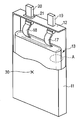
- FIG. 2 is a partially cutaway perspective view of a thin nonaqueous electrolyte secondary battery
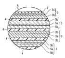
- FIG. 3 is an enlarged cross-sectional view of a portion A in FIG.
- Each figure is a schematic diagram for promoting explanation and understanding of the invention, and its shape, dimensions, ratio, etc. are different from the actual apparatus, but these are considered in consideration of the following explanation and known techniques. The design can be changed as appropriate.
- the wound electrode group 13 is housed in a rectangular exterior material 11 made of a laminate film in which an aluminum foil is interposed between two resin layers.
- the flat wound electrode group 13 is formed by winding a laminate of the negative electrode 3, the separator 4, the positive electrode 5, and the separator 4 in this order from the outside in a spiral shape and press-molding.
- the negative electrode tab 18 has one end connected to the negative electrode current collector 3a and the other end connected to a negative electrode terminal 20 fixed to the rectangular lid 12 via a negative electrode gasket.
- the positive electrode tab 17 has one end connected to the positive electrode current collector 5 a and the other end connected to a positive electrode terminal 19 fixed to the rectangular lid 12.
- the non-aqueous electrolyte is, for example, injected from an opening of the rectangular outer packaging material 11 and accommodated in the rectangular outer packaging material 11.
- the rectangular exterior material 11 is sealed with the wound electrode group 13 and the non-aqueous electrolyte by heat-sealing the rectangular lid 12 at the opening.
- the negative electrode tab for example, a material having electrical stability and conductivity in a range where the potential with respect to the lithium ion metal is 1.0 V or more and 3.0 V or less can be used. Specifically, aluminum or an aluminum alloy containing elements such as Mg, Ti, Zn, Mn, Fe, Cu, and Si can be given.
- the negative electrode tab is preferably made of the same material as the negative electrode current collector in order to reduce contact resistance with the negative electrode current collector.
- the positive electrode tab may be made of a material having electrical stability and conductivity in a range of the potential with respect to the lithium ion metal being 3.0 V or more and 4.25 V or less. Specifically, aluminum or an aluminum alloy containing elements such as Mg, Ti, Zn, Mn, Fe, Cu, and Si can be given.
- the positive electrode tab is preferably made of the same material as the positive electrode current collector in order to reduce the contact resistance with the positive electrode current collector.
- the battery pack according to the second embodiment of the present invention includes at least one nonaqueous electrolyte battery according to the first embodiment as a unit cell. When a plurality of unit cells are provided, they are electrically connected in series or in parallel to constitute an assembled battery.
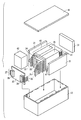
- FIG. 4 is an exploded perspective view of the battery pack according to the second embodiment.
- a plurality of (for example, eight) flat unit cells 41 are stacked in the thickness direction to form a battery stack 40 having a rectangular parallelepiped shape, that is, an assembled battery.
- the positive electrode terminal 33 and the negative electrode terminal 34 connected to the positive electrode and the negative electrode, respectively are drawn out of the exterior material.
- a printed wiring board 32 is disposed on the side surface from which the positive electrode terminal 33 and the negative electrode terminal 34 protrude.
- the positive terminal 33 is electrically connected to the positive connector 36 via the positive wiring 35.
- the negative electrode terminal 34 is electrically connected to the negative electrode side connector 38 via the negative electrode side wiring 37.
- the laminated body 40 of the unit cells 41 is fixed by an adhesive tape 39.
- protective sheets 31 made of rubber or resin are disposed on three side surfaces other than the side surfaces from which the positive electrode terminal 33 and the negative electrode terminal 34 protrude.
- a block-shaped protection block 42 made of rubber or resin is disposed between the side surface from which the positive electrode terminal 33 and the negative electrode terminal 34 protrude and the printed wiring board 32.
- the laminated body 40 is stored in the storage container 43 together with each protective sheet 31, the protective block 42 and the printed wiring board 32.
- a lid 44 is attached to the upper surface of the storage container 43.
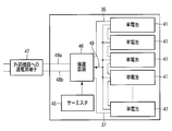
- a thermistor 45 As shown in FIG. 5, a thermistor 45, a protection circuit 46, and a terminal 47 for energizing external devices are mounted on the printed wiring board 32.
- the thermistor 45 is for detecting the temperature of the unit cell 41, and the detection signal is transmitted to the protection circuit 46.
- the protection circuit 46 can cut off the wirings 48a and 48b between the protection circuit 46 and a terminal 47 for energization to an external device under a predetermined condition.
- the predetermined condition is, for example, when the detected temperature of the thermistor 45 is equal to or higher than a predetermined temperature, or when overcharge, overdischarge, overcurrent, or the like of the unit cell 41 is detected.
- This detection method is performed for each individual cell 41 or the entire cell.
- the battery voltage may be detected, or the positive electrode potential or the negative electrode potential may be detected. In the latter case, a lithium electrode used as a reference electrode is inserted into each unit cell 41.
- the protection circuit 46 includes a battery voltage monitoring circuit unit.
- Each of the single cells 41 is connected to the battery voltage monitoring circuit unit through the wiring 49. According to such a configuration, the battery voltage of each single cell 41 can be detected by the protection circuit 46.
- a heat shrink tape may be used.
- the protective sheet 31 is disposed on both side surfaces of the laminated body 40 and the heat shrinkable tube is circulated, and then the heat shrinkable tube is thermally contracted to bind the laminated body 40.
- unit cells 41 shown in FIG. 4 are connected in series, they may be connected in parallel in order to increase the capacity of the battery pack.
- the assembled battery packs can be connected in series and in parallel.
- the aspect of a battery pack is changed suitably by a use.
- the automobile according to the third embodiment includes the battery pack according to the second embodiment.
- Examples of the vehicle herein include a two-wheel to four-wheel hybrid electric vehicle, a two-wheel to four-wheel electric vehicle, and an assist bicycle.
- FIGS. 6 to 8 show a hybrid type vehicle using a driving power source by combining an internal combustion engine and a battery-driven electric motor.
- the driving force of an automobile requires a power source with a wide range of rotation speeds and torques depending on the running conditions.
- an internal combustion engine has a limited torque and rotational speed that show ideal energy efficiency. Therefore, the energy efficiency decreases under other operating conditions.
- Hybrid type automobiles generate power by operating an internal combustion engine under optimum conditions, and by driving wheels with a high-efficiency electric motor, or by driving the internal combustion engine and the electric motor together. The overall energy efficiency can be improved. Further, by regenerating the kinetic energy of the vehicle as electric power during deceleration, the travel distance per unit fuel can be dramatically increased compared to a normal internal combustion engine vehicle.
- Hybrid vehicles can be broadly classified into three types depending on how the internal combustion engine and electric motor are combined.
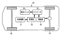
- FIG. 6 shows a hybrid vehicle 50 generally called a series hybrid vehicle. All the power of the internal combustion engine 51 is once converted into electric power by the generator 52, and this electric power is stored in the battery pack 54 through the inverter 53.
- the battery pack 54 the battery pack according to the second embodiment of the present invention is used.
- the electric power of the battery pack 54 is supplied to the electric motor 55 through the inverter 53, and the wheels 56 are driven by the electric motor 55.
- It is a system in which a generator is combined with an electric vehicle.
- the internal combustion engine can be operated under highly efficient conditions and can also regenerate power. On the other hand, since driving of the wheels is performed only by the electric motor, a high-output electric motor is required. Also, a battery pack having a relatively large capacity is required.
- the rated capacity of the battery pack is preferably in the range of 5 to 50 Ah. A more preferable range is 10 to 20 Ah.
- the rated capacity means a capacity when discharged at a 0.2 C rate.
- FIG. 7 shows a hybrid vehicle 57 called a parallel hybrid vehicle.
- Reference numeral 58 indicates an electric motor that also serves as a generator.
- the internal combustion engine 51 mainly drives the wheels 56, and in some cases, a part of the power is converted into electric power by the generator 58, and the battery pack 54 is charged with the electric power.
- the driving force is assisted by the electric motor 58 at the time of start and acceleration where the load becomes heavy.
- This is a system based on a normal automobile, which reduces the load fluctuation of the internal combustion engine 51 to improve efficiency and also performs power regeneration.
- the output of the electric motor 58 can be arbitrarily determined depending on the necessary auxiliary ratio.
- the system can also be configured using a relatively small electric motor 58 and battery pack 54.
- the rated capacity of the battery pack can be in the range of 1 to 20 Ah. A more preferred range is 5 to 10 Ah.
- FIG. 8 shows a hybrid vehicle 59 called a series / parallel hybrid vehicle. This is a combination of both series and parallel.
- the power split mechanism 60 splits the output of the internal combustion engine 51 into power generation and wheel drive.
- the engine load can be controlled more finely than the parallel system, and energy efficiency can be improved.
- the rated capacity of the battery pack be in the range of 1 to 20 Ah.
- a more preferred range is 5 to 10 Ah.
- the nominal voltage of the battery pack mounted on the hybrid vehicle as shown in FIGS. 6 to 8 is preferably in the range of 200 to 600V.
- the battery pack 54 is preferably disposed in a place that is generally less susceptible to changes in the outside air temperature and is less susceptible to impact during a collision or the like.
- a sedan type automobile as shown in FIG. 9 can be arranged in the trunk room 62 behind the rear seat 61. Further, it can be placed under or behind the seat 61.
- the battery weight is large, it is preferable to arrange the battery under the seat or under the floor in order to lower the center of gravity of the entire vehicle.
- Example 1 ⁇ Preparation of positive electrode> LiNiO 2 (lithium release capacity during initial charge: 215 mAh / g, lithium storage capacity during initial discharge: 180 mAh / g) as a positive electrode active material, graphite and acetylene black as a conductive agent, and PVdF as a binder were used.
- a slurry was prepared by adding 88 parts by mass of LiNiO 2 , 3 parts by mass of graphite, 4 parts by mass of acetylene black and 5 parts by mass of PVdF to N-methylpyrrolidone (NMP) and mixing them. This slurry is applied to both sides of a 15 ⁇ m thick aluminum foil (current collector), dried and then pressed to form an active material-containing layer having a thickness of 28 ⁇ m on one side of the current collector.
- NMP N-methylpyrrolidone
- NMP N-methylpyrrolidone
- Ethylene carbonate (EC), propylene carbonate (PC), and ⁇ -butyrolactone (GBL) were mixed at a volume ratio of 1: 1: 4 to obtain a mixed solvent.
- a non-aqueous electrolyte was prepared by mixing 2M LiBF 4 in this mixed solvent.
- ⁇ Battery assembly> Prepared a container with a bottomed rectangular tube made of aluminum with a thickness of 0.3 mm and an aluminum lid with a positive electrode terminal inserted and a negative electrode terminal inserted by caulking through an insulating resin did. After impregnating a separator made of a polyethylene porous film with a non-aqueous electrolyte, this separator covers both surfaces of the positive electrode, and the negative electrode is wound so as to face the positive electrode through the separator and wound in a spiral shape. A spiral electrode group having an extended lead tab was prepared. This electrode group was pressed into a flat shape.
- Example 2 The battery was prepared in the same manner as in Example 1 except that LiNi 0.81 Co 0.16 Al 0.03 O 2 (lithium release capacity at the first charge: 209 mAh / g, lithium storage capacity at the first discharge 175 mAh / g) was used as the positive electrode active material. Produced.
- Example 3 Li 4 Ti 5 O 12 as a negative electrode active material (lithium storage capacity at initial charge: 160 mAh / g, lithium release capacity at first discharge: 152 mAh / g) and CoPO 4 (lithium storage capacity: 185 mAh / g), graphite as a conductive agent PVdF was used as a binder. CoPO 4 supported 3% of carbon with respect to the mass of CoPO 4 .
- NMP N-methylpyrrolidone
- Example 4 Li 4 Ti 5 O 12 (lithium occlusion capacity at initial charge: 160 mAh / g, lithium discharge capacity at initial discharge: 152 mAh / g) and Fe 0.5 Mn 0.5 PO 4 (lithium occlusion capacity: 189 mAh / g) as a negative electrode active material, Graphite was used as the conductive agent and PVdF was used as the binder. Fe 0.5 Mn 0.5 PO 4 supported 3% of carbon with respect to the mass of Fe 0.5 Mn 0.5 PO 4 .
- NMP N-methylpyrrolidone
- Example 5 Li 4 Ti 5 O 12 as negative electrode active material (lithium storage capacity at initial charge: 160 mAh / g, lithium release capacity at first discharge: 152 mAh / g) MnPO 4 (lithium storage capacity: 190 mAh / g), graphite as conductive agent, PVdF was used as a binder. MnPO 4 supported 3% of carbon with respect to the mass of MnPO 4 .
- NMP N-methylpyrrolidone
- Example 6 A battery was prepared in the same manner as in Example 1 except that LiNi 0.80 Co 0.15 Al 0.05 O 2 (lithium release capacity at the first charge: 207 mAh / g, lithium storage capacity at 173 mAh / g at the first discharge) was used as the positive electrode active material. Produced.
- Example 7 The battery was prepared in the same manner as in Example 1 except that LiNi 0.84 Co 0.15 Al 0.01 O 2 (lithium release capacity at the first charge: 210 mAh / g, lithium storage capacity at the first discharge 176 mAh / g) was used as the positive electrode active material. Produced.
- Example 8 A battery was produced in the same manner as in Example 1 except that LiNi 0.85 Co 0.15 O 2 (lithium release capacity at the first charge: 211 mAh / g, lithium storage capacity at the first discharge 178 mAh / g) was used as the positive electrode active material. .
- Example 2 The same as Example 2 except that Li 4 Ti 5 O 12 was used as the negative electrode active material, and a negative electrode having a composition of 89 parts by mass of Li 4 Ti 5 O 12 , 6 parts by mass of graphite and 5 parts by mass of PVdF was used.
- a battery was prepared by various methods.
- Example 3 A battery was prepared in the same manner as in Example 1 except that MCF (mesophase carbon pitch fiber) was used as the negative electrode active material, and a negative electrode having a composition of 75 parts by mass of MCF, 20 parts by mass of graphite and 5 parts by mass of PVdF was used.
- MCF meophase carbon pitch fiber
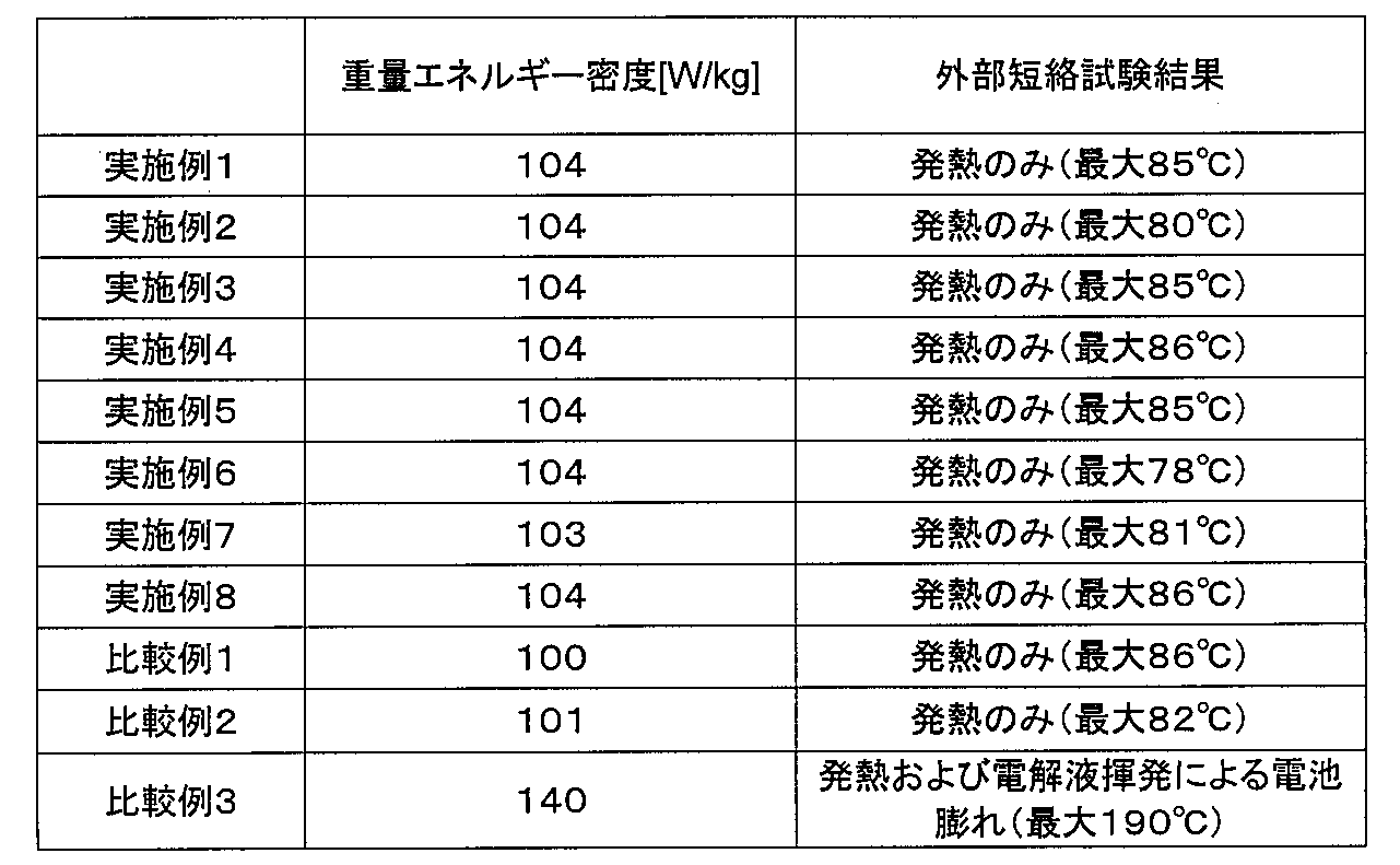
- the mass energy density of the battery was charged until the battery voltage reached 2.8 V (Examples 1 to 8 and Comparative Examples 1 and 2) or 4.2 V (Comparative Example 3) at a 1/20 C rate.
- temperature was measured in the part which attached
- an embodiment comprising a positive electrode having a positive electrode layer containing a lithium nickel composite oxide as an active material, and a negative electrode having a negative electrode layer containing a lithium-titanium composite oxide as an active material together with a lithium titanium composite oxide.
- the non-aqueous electrolyte secondary batteries of Examples 1 to 8 are higher in mass energy density than the secondary batteries of Comparative Examples 1 and 2 having a negative electrode layer having a negative electrode layer containing only the positive electrode and lithium titanium composite oxide as active materials. Is expensive.
- the nonaqueous electrolyte secondary batteries of Examples 1 to 8 had a maximum temperature higher than that of Comparative Examples 1 and 2 including a negative electrode having a negative electrode layer containing only lithium titanium composite oxide as an active material. It was shown that addition of lithium-containing phosphorous oxide to the negative electrode active material does not affect the safety of the battery.
- nonaqueous electrolyte secondary battery of Comparative Example 3 having a positive electrode having a positive electrode layer containing a lithium nickel composite oxide as an active material and a negative electrode having a negative electrode layer containing MCF as an active material has a large mass energy density, In the short-circuit test, heat generation was large and battery swelling due to volatilization of the electrolyte was confirmed, indicating that the safety was low.
- the example applied to the thin non-aqueous electrolyte secondary battery has been described in the above-described embodiments, it can be similarly applied to a cylindrical non-aqueous electrolyte secondary battery, a rectangular non-aqueous electrolyte secondary battery, and the like.
- the electrode group housed in the battery container is not limited to the spiral shape, and a plurality of positive electrodes, separators, and negative electrodes may be stacked in this order.
- the present invention is not limited to the above-described embodiments as they are, and can be embodied by modifying the constituent elements without departing from the scope of the invention in the implementation stage.
- various inventions can be formed by appropriately combining a plurality of components disclosed in the embodiment. For example, some components may be deleted from all the components shown in the embodiment.
- constituent elements over different embodiments may be appropriately combined.
Landscapes
- Chemical & Material Sciences (AREA)
- Chemical Kinetics & Catalysis (AREA)
- Electrochemistry (AREA)
- General Chemical & Material Sciences (AREA)
- Inorganic Chemistry (AREA)
- Engineering & Computer Science (AREA)
- Materials Engineering (AREA)
- Manufacturing & Machinery (AREA)
- General Physics & Mathematics (AREA)
- Condensed Matter Physics & Semiconductors (AREA)
- Physics & Mathematics (AREA)
- Crystallography & Structural Chemistry (AREA)
- Secondary Cells (AREA)
- Battery Electrode And Active Subsutance (AREA)
Abstract
Description
75≦b/a≦90 (2)
90≦y/x<100 (3)
x<z (4)
0<γ/β≦(ay-bx)/bz (5)
ここにおいて、
aは、前記リチウムニッケル複合酸化物の初回充電時のリチウム放出容量[mAh/g]であり、
bは、前記リチウムニッケル複合酸化物の初回放電時のリチウム吸蔵容量[mAh/g]であり、
xは、前記リチウムチタン複合酸化物の初回充電時のリチウム吸蔵容量[mAh/g]であり、
yは、前記リチウムチタン複合酸化物の初回放電時のリチウム放出容量[mAh/g]であり、
zは、前記リチウム含有リン酸化物のリチウム吸蔵容量[mAh/g]であり、
βは、前記リチウムチタン複合酸化物の質量[g]であり、
γは、前記リチウム含有リン酸化物の質量[g]である。
実施形態に係る非水電解質二次電池は、リチウムニッケル複合酸化物を含む正極と、リチウムチタン複合酸化物及びリチウム含有リン酸化物を含む活物質を含む負極と、非水電解質とを備える。
75≦b/a≦90 (2)
90≦y/x<100 (3)
x<z (4)
0<γ/β≦(ay-bx)/bz (5)
ここにおいて、
aは、前記リチウムニッケル複合酸化物の初回充電時のリチウム放出容量[mAh/g]であり、
bは、前記リチウムニッケル複合酸化物の初回放電時のリチウム吸蔵容量[mAh/g]であり、
xは、前記リチウムチタン複合酸化物の初回充電時のリチウム吸蔵容量[mAh/g]であり、
yは、前記リチウムチタン複合酸化物の初回放電時のリチウム放出容量[mAh/g]であり、
zは、前記リチウム含有リン酸化物のリチウム吸蔵容量[mAh/g]であり、
βは、前記リチウムチタン複合酸化物の質量[g]であり、
γは、前記リチウム含有リン酸化物の質量[g]である。
前記リチウムニッケル複合酸化物と導電剤とバインダーからなる電極を作用極、リチウム金属を対極および参照極とした3電極式セルを作製する。この充放電を行っていない3電極式セルの作用極の電位がリチウム金属に対して4.25Vに達するまで0.1C以下の電流値で定電流充電を行う。ここで1Cとは該当電池の定格容量を1時間で放電する際に必要な電流値である。作用極の電位が4.25Vに達した後はその電位での定電圧充電を10時間行ったときのリチウム放出容量をaとする(初回充電)。この充電状態の3電極式セルを作用極の電位が金属リチウムに対して3.0Vに達するまで0.1C以下の電流値で定電流放電行った際のリチウム吸蔵容量をbとする(初回放電)。
αb=βy 式(A)
βx+γz=αa 式(B)
が同時に成り立つときであり、このときのγ/βの値は(ay-bx)/bzとなる。
本発明の第1の実施形態に係る非水電解質二次電池は、正極と、負極と、非水電解質と、正負極間に介装されたセパレータとを備える。負極、正極及びセパレータからなる電極群は、外装材に収納され、非水電解質が少なくとも電極群に含有される。
以下、正極、負極、非水電解質、セパレータ、外装材について詳細に説明する。
正極は、正極集電体と、正極集電体の片面又は両面に形成され、正極活物質、導電剤及び結着剤を含む正極層とを有する。
酸化物は、例えば二酸化マンガン(MnO2)、酸化鉄、酸化銅、酸化ニッケル、LiaMnO2、リチウムコバルト複合酸化物(LiaCoO2)、リチウムマンガンコバルト複合酸化物、例えばLiMn1-g-hCogMhO2(ここで、MはAl、Cr、Mg及びFeから選択される少なくとも1つ又は2つ以上の元素であり、0≦g≦0.5、0≦h≦0.1である)、リチウムマンガンニッケル複合酸化物、例えばLiMnjNijM1-2jO2(ここで、MはCo、Cr、Al、Mg及びFeから選択される少なくとも1つ又は2つ以上の元素であり、1/3≦j≦1/2、たとえばLiMn1/3Ni1/3Co1/3O2、LiMn1/2Ni1/2O2である)、スピネル構造を有するリチウムマンガン複合酸化物、例えばLiaMn2-bMbO4(ここで、MはAl、Cr、Ni及びFeから選択される少なくとも1つ又は2つ以上の元素である)、スピネル構造を有するリチウムマンガンニッケル複合酸化物(例えばLiaMn2-bNibO4)、オリビン構造を有するリチウム含有リン酸化物(例えばLiaFePO4、LiaFe1-bMnbPO4、LiaCoPO4など)、又はバナジウム酸化物(例えばV2O5)を用いることができる。ここで、a、b、cは0~1であることが好ましい。
集電体を構成するアルミニウム箔又はアルミニウム合金箔は、50μm以下、より好ましくは30μm以下、更に好ましくは5μm以下の平均結晶粒径を有することが好ましい。平均結晶粒径が50μm以下であると、アルミニウム箔又はアルミニウム合金箔の強度が飛躍的に増大する。このため、プレス時の圧力を高めて正極活物質含有層を高密度化し、正極容量を増大させることが可能である。
アルミニウム箔又はアルミニウム合金箔の平均結晶粒径は、材料組織、不純物、加工条件、熱処理履歴、並びに焼鈍条件など複数の因子から複雑な影響を受けて変化する。結晶粒径は、集電体の製造工程の中で、前記諸因子を組合せて調整することが可能である。
負極は、負極集電体と、負極集電体の片面又は両面に形成され、負極活物質、導電剤及び結着剤を含む負極層とを有する。
リチウムチタン複合酸化物としては、例えばLi4+xTi5O12(-1≦x≦3)で表されるスピネル構造を有するチタン酸リチウム、又は、ラムステライド構造を有するLi2+xTi3O7(-1≦x≦3)を用いることができる。
炭素質物は、例えば天然黒鉛、人造黒鉛、コークス、気相成長炭素繊維、メソフェーズピッチ系炭素繊維、球状炭素、樹脂焼成炭素を用いることができる。特に、気相成長炭素繊維、メソフェーズピッチ系炭素繊維、球状炭素を用いることが好ましい。炭素質物は、X線回折による(002)面の面間隔d=002が0.340nm以下であることが好ましい。
集電体を構成するアルミニウム箔又はアルミニウム合金箔は、50μm以下、より好ましくは30μm以下、更に好ましくは5μm以下の平均結晶粒径を有することが好ましい。平均結晶粒径が50μm以下であると、アルミニウム箔又はアルミニウム合金箔の強度が飛躍的に増大する。このため、プレス時の圧力を高めて負極活物質含有層を高密度化し、負極容量を増大させることが可能である。また、高温環境下(40℃以上)における過放電サイクルでの集電体の溶解・腐食劣化を防ぐことができる。このため、負極インピーダンスの上昇を抑制することができる。さらに、出力特性、急速充電、充放電サイクル特性も向上させることができる。
非水電解質は、非水溶媒に電解質を溶解することにより調製される液体状非水電解質(非水電解液)、高分子材料に前記非水溶媒と前記電解質を含有した高分子ゲル状電解質、高分子材料に前記電解質を含有した高分子固体電解質、又はリチウムイオン伝導性を有する無機固体電解質を用いることができる。
正極と負極の間には、セパレータを配置することができる。このセパレータと併せてゲル状もしくは固体の非水電解質層を用いてもよいし、セパレータの代わりにゲル状もしくは固体の非水電解質層を用いることも可能である。
外装材は、厚さ0.5mm以下のラミネートフィルム又は厚さ1.0mm以下の金属製容器が用いられる。金属製容器は、厚さ0.5mm以下であることがより好ましい。
本発明の第2の実施形態に係る電池パックは、第1の実施形態に係る非水電解質電池を単電池として一以上備える。複数の単電池を備える場合は、電気的に直列もしくは並列に接続されており、組電池を構成している。
図4に示すように、複数個(例えば8個)の平板状の単電池41が厚さ方向に積層されており、直方体状を為す電池積層体40、つまり組電池が形成されている。各単電池41は、上述したように、正極および負極夫々に接続された正極端子33および負極端子34が外装材の外部に引き出されている。正極端子33および負極端子34が突出する側面に対しては、プリント配線基板32が配置される。
第3の実施形態に係る自動車は、第2の実施形態に係る電池パックを備える。ここでいう自動車としては、二輪~四輪のハイブリッド電気自動車、二輪~四輪の電気自動車、アシスト自転車などが挙げられる。
<正極の作製>
正極活物質としてLiNiO2(初回充電時リチウム放出容量:215mAh/g、初回放電時リチウム吸蔵容量180mAh/g)、導電剤としてグラファイト及びアセチレンブラック、結着剤としてPVdFを用いた。
88質量部のLiNiO2、3質量部のグラファイト、4質量部のアセチレンブラック及び5質量部のPVdFを、N-メチルピロリドン(NMP)に加えて混合してスラリーを調製した。このスラリーを厚さ15μmのアルミニウム箔(集電体)の両面に塗布し、乾燥後、プレスすることにより成型し、片面の厚さが28μmの活物質含有層が集電体の両面に形成された正極を作製した。
負極活物質としてLi4Ti5O12(初回充電時リチウム吸蔵容量:160mAh/g、初回放電時リチウム放出容量:152mAh/g)とFePO4(リチウム吸蔵容量:189mAh/g)、導電剤としてグラファイト、結着剤としてPVdFを用いた。FePO4は、FePO4の質量に対して3%のカーボンを担持させた。
エチレンカーボネート(EC)とプロピレンカーボネート(PC)とγ-ブチロラクトン(GBL)とを体積比で1:1:4の割合で混合して混合溶媒とした。この混合溶媒に2MのLiBF4を混合して非水電解質を調製した。
厚さ0.3mmのアルミニウム製の有底矩形状筒体の容器と、正極端子が挿着されるとともに負極端子が絶縁性の樹脂を介してかしめにより挿着されたアルミニウム製の蓋体を用意した。非水電解質をポリエチレン製多孔質フィルムからなるセパレータに含浸した後、このセパレータで正極の両面を覆い、負極をセパレータを介して正極と対向するように重ねて渦巻状に捲回し、正極及び負極からそれぞれ延出したリードタブを有する渦巻状の電極群を作製した。この電極群をプレスして扁平状に成形した。扁平状に成形した電極群の正極リードタブを蓋体の正極端子の一端に接続し、負極リードタブを負極端子の一端に接続し、電極群を蓋体と共に容器の開口部を通してその内部に挿入し、蓋体を容器の開口部に溶接した。これらの工程により、前述した図2に示す構造を有し、厚さ3.0mm、幅35mm、高さ62mmの薄型非水電解質二次電池を製造した。
正極活物質にLiNi0.81Co0.16Al0.03O2(初回充電時リチウム放出容量:209mAh/g、初回放電時リチウム吸蔵容量175mAh/g)を用いた以外は、実施例1と同様な方法により電池を作製した。
負極活物質としてLi4Ti5O12(初回充電時リチウム吸蔵容量:160mAh/g、初回放電時リチウム放出容量:152mAh/g)とCoPO4(リチウム吸蔵容量:185mAh/g)、導電剤としてグラファイト、結着剤としてPVdFを用いた。CoPO4は、CoPO4の質量に対して3%のカーボンを担持させた。
負極活物質としてLi4Ti5O12(初回充電時リチウム吸蔵容量:160mAh/g、初回放電時リチウム放出容量:152mAh/g)とFe0.5Mn0.5PO4(リチウム吸蔵容量:189mAh/g)、導電剤としてグラファイト、結着剤としてPVdFを用いた。Fe0.5Mn0.5PO4は、Fe0.5Mn0.5PO4の質量に対して3%のカーボンを担持させた。
負極活物質としてLi4Ti5O12(初回充電時リチウム吸蔵容量:160mAh/g、初回放電時リチウム放出容量:152mAh/g)MnPO4(リチウム吸蔵容量:190mAh/g)、導電剤としてグラファイト、結着剤としてPVdFを用いた。MnPO4は、MnPO4の質量に対して3%のカーボンを担持させた。
正極活物質にLiNi0.80Co0.15Al0.05O2(初回充電時リチウム放出容量:207mAh/g、初回放電時リチウム吸蔵容量173mAh/g)を用いた以外は、実施例1と同様な方法により電池を作製した。
正極活物質にLiNi0.84Co0.15Al0.01O2(初回充電時リチウム放出容量:210mAh/g、初回放電時リチウム吸蔵容量176mAh/g)を用いた以外は、実施例1と同様な方法により電池を作製した。
正極活物質にLiNi0.85Co0.15O2(初回充電時リチウム放出容量:211mAh/g、初回放電時リチウム吸蔵容量178mAh/g)を用いた以外は、実施例1と同様な方法により電池を作製した。
負極活物質にLi4Ti5O12を用い、Li4Ti5O12を89質量部、グラファイトを6質量部及びPVdFを5質量部の組成の負極を用いた以外は、実施例1と同様な方法により電池を作製した。
負極活物質にLi4Ti5O12を用い、Li4Ti5O12を89質量部、グラファイトを6質量部及びPVdFを5質量部の組成の負極を用いた以外は、実施例2と同様な方法により電池を作製した。
負極活物質にMCF(メソフェーズカーボンピッチファイバー)を用い、MCFを75質量部、グラファイトを20質量部及びPVdFを5質量部の組成の負極を用いた以外は、実施例1と同様な方法により電池を作製した。
Claims (8)
- リチウムニッケル複合酸化物を含む正極と、リチウムチタン複合酸化物及びリチウム含有リン酸化物を含む負極と、非水電解質とを含み、下式(1)~(5)を満たす非水電解質二次電池:
b/a<y/x (1)
75≦b/a≦90 (2)
90≦y/x<100 (3)
x<z (4)
0<γ/β≦(ay-bx)/bz (5)
ここにおいて、
aは、前記リチウムニッケル複合酸化物の初回充電時のリチウム放出容量[mAh/g]であり、
bは、前記リチウムニッケル複合酸化物の初回放電時のリチウム吸蔵容量[mAh/g]であり、
xは、前記リチウムチタン複合酸化物の初回充電時のリチウム吸蔵容量[mAh/g]であり、
yは、前記リチウムチタン複合酸化物の初回放電時のリチウム放出容量[mAh/g]であり、
zは、前記リチウム含有リン酸化物のリチウム吸蔵容量[mAh/g]であり、
βは、前記リチウムチタン複合酸化物の質量[g]であり、
γは、前記リチウム含有リン酸化物の質量[g]である。 - 前記リチウムチタン複合酸化物は、Li4+xTi5O12(-1≦x≦3)で表されるスピネル構造を有するチタン酸リチウムである、請求項1に記載の非水電解質二次電池。
- 前記リチウム含有リン酸化物は、LisFePO4(0<s≦1.15)、LisFe1-tMntPO4(0<s≦1.15、0≦t≦1)及びLisCoPO4(0<s≦1.15)から選択される、オリビン構造を有する酸化物を含む、請求項1に記載の非水電解質二次電池。
- 前記リチウムチタン複合酸化物は、Li4+xTi5O12(-1≦x≦3)で表されるスピネル構造を有するチタン酸リチウムであり、且つ、
前記リチウム含有リン酸化物は、LisFePO4(0<s≦1.15)、LisFe1-tMntPO4(0<s≦1.15、0≦t≦1)及びLisCoPO4(0<s≦1.15)から選択される、オリビン構造を有する酸化物を含む、請求項1に記載の非水電解質二次電池。 - 前記非水電解質は、プロピレンカーボネートを含む、請求項1に記載の非水電解質二次電池。
- 前記負極は、前記リチウム含有リン酸化物に担持されるカーボンをさらに含む、請求項1に記載の非水電解質二次電池。
- 請求項1に記載の非水電解質二次電池を一以上具備することを特徴とする電池パック。
- 請求項7に記載の電池パックを具備することを特徴とする自動車。
Priority Applications (4)
| Application Number | Priority Date | Filing Date | Title |
|---|---|---|---|
| KR1020117017620A KR101368602B1 (ko) | 2009-02-03 | 2010-02-03 | 비수 전해질 이차 전지, 전지 팩 및 자동차 |
| CN201080006442.7A CN102308424B (zh) | 2009-02-03 | 2010-02-03 | 非水电解质二次电池、电池组及汽车 |
| JP2010549493A JP5611845B2 (ja) | 2009-02-03 | 2010-02-03 | 非水電解質二次電池、電池パック及び自動車 |
| US13/197,141 US8334074B2 (en) | 2009-02-03 | 2011-08-03 | Nonaqueous electrolyte secondary battery having a negative electrode comprising a lithium-containing phosphorous oxide, a battery pack and vehicle containing the battery |
Applications Claiming Priority (2)
| Application Number | Priority Date | Filing Date | Title |
|---|---|---|---|
| JP2009-022663 | 2009-02-03 | ||
| JP2009022663 | 2009-02-03 |
Related Child Applications (1)
| Application Number | Title | Priority Date | Filing Date |
|---|---|---|---|
| US13/197,141 Continuation US8334074B2 (en) | 2009-02-03 | 2011-08-03 | Nonaqueous electrolyte secondary battery having a negative electrode comprising a lithium-containing phosphorous oxide, a battery pack and vehicle containing the battery |
Publications (1)
| Publication Number | Publication Date |
|---|---|
| WO2010090224A1 true WO2010090224A1 (ja) | 2010-08-12 |
Family
ID=42542117
Family Applications (1)
| Application Number | Title | Priority Date | Filing Date |
|---|---|---|---|
| PCT/JP2010/051518 Ceased WO2010090224A1 (ja) | 2009-02-03 | 2010-02-03 | 非水電解質二次電池、電池パック及び自動車 |
Country Status (5)
| Country | Link |
|---|---|
| US (1) | US8334074B2 (ja) |
| JP (1) | JP5611845B2 (ja) |
| KR (1) | KR101368602B1 (ja) |
| CN (1) | CN102308424B (ja) |
| WO (1) | WO2010090224A1 (ja) |
Cited By (3)
| Publication number | Priority date | Publication date | Assignee | Title |
|---|---|---|---|---|
| US10727540B2 (en) | 2016-02-01 | 2020-07-28 | Kabushiki Kaisha Toshiba | Secondary battery, battery module, battery pack and vehicle |
| US10862165B2 (en) | 2012-07-10 | 2020-12-08 | Lg Chem, Ltd. | Secondary battery including electrolyte additive |
| JP2026506266A (ja) * | 2023-07-14 | 2026-02-24 | エルジー エナジー ソリューション リミテッド | 負極活物質、負極活物質の製造方法、負極組成物、これを含むリチウム二次電池用負極、および負極を含むリチウム二次電池 |
Families Citing this family (10)
| Publication number | Priority date | Publication date | Assignee | Title |
|---|---|---|---|---|
| JP6246019B2 (ja) * | 2013-02-27 | 2017-12-13 | 株式会社大阪ソーダ | 正極および非水電解質二次電池 |
| CN104282934B (zh) * | 2013-07-10 | 2017-03-15 | 万向一二三股份公司 | 新型高能量密度动力电池 |
| US9205755B2 (en) * | 2014-01-14 | 2015-12-08 | Ford Global Technologies, Llc | Receding horizon regression analysis for battery impedance parameter estimation |
| EP2945211B1 (en) * | 2014-05-15 | 2018-11-21 | Saft Groupe S.A. | Lithium titanate oxide as negative electrode in li-ion cells |
| US10050302B2 (en) * | 2014-07-22 | 2018-08-14 | Rekrix Co., Ltd. | Silicon secondary battery |
| US10530012B2 (en) * | 2014-11-18 | 2020-01-07 | Zeon Corporation | Method for producing an electrochemical device |
| EP3367490B1 (en) * | 2015-09-16 | 2019-07-31 | Kabushiki Kaisha Toshiba | Secondary battery, battery pack, and vehicle |
| DE102017220232A1 (de) * | 2017-11-14 | 2019-05-16 | VW-VM Forschungsgesellschaft mbH & Co. KG | Dünne, sekundäre Miniaturzelle mit metallischem, mittels eines Kunststoffdeckels verschlossenem Gehäuse und Verfahren zu ihrer Herstellung |
| JP7131124B2 (ja) * | 2018-06-25 | 2022-09-06 | トヨタ自動車株式会社 | 組電池、車両、および組電池の製造方法 |
| US12199282B2 (en) | 2020-09-18 | 2025-01-14 | WATTRII Inc. | Halogenated battery comprising a greenhouse gas |
Citations (5)
| Publication number | Priority date | Publication date | Assignee | Title |
|---|---|---|---|---|
| JP2005135775A (ja) * | 2003-10-30 | 2005-05-26 | Yuasa Corp | リチウムイオン二次電池 |
| JP2006066341A (ja) * | 2004-08-30 | 2006-03-09 | Toshiba Corp | 非水電解質二次電池 |
| JP2008091326A (ja) * | 2006-09-05 | 2008-04-17 | Gs Yuasa Corporation:Kk | 非水電解質電池 |
| JP2008243612A (ja) * | 2007-03-27 | 2008-10-09 | Toshiba Corp | 非水電解質電池、電池パック及び自動車 |
| JP2010009898A (ja) * | 2008-06-26 | 2010-01-14 | Hitachi Maxell Ltd | 非水二次電池および非水二次電池システム |
Family Cites Families (7)
| Publication number | Priority date | Publication date | Assignee | Title |
|---|---|---|---|---|
| JP2001023629A (ja) | 1999-07-12 | 2001-01-26 | Kawatetsu Mining Co Ltd | リチウムイオン二次電池正極用活物質およびリチウムイオン二次電池正極活物質の熱安定性の評価方法 |
| CN100433447C (zh) * | 2004-09-24 | 2008-11-12 | 株式会社东芝 | 蓄电系统、再生蓄电系统和汽车 |
| JP4439456B2 (ja) | 2005-03-24 | 2010-03-24 | 株式会社東芝 | 電池パック及び自動車 |
| JP4445447B2 (ja) | 2005-09-15 | 2010-04-07 | 株式会社東芝 | 非水電解質電池および電池パック |
| JP4557920B2 (ja) | 2006-03-30 | 2010-10-06 | 株式会社東芝 | 非水電解質電池 |
| JP4445537B2 (ja) * | 2007-09-26 | 2010-04-07 | 株式会社東芝 | 二次電池、電池パック及び車 |
| DE102008001120B4 (de) * | 2008-04-10 | 2014-10-16 | Sineurop Nanotech Gmbh | Verfahren zur Herstellung eines Elektrodenmaterials |
-
2010
- 2010-02-03 CN CN201080006442.7A patent/CN102308424B/zh not_active Expired - Fee Related
- 2010-02-03 KR KR1020117017620A patent/KR101368602B1/ko not_active Expired - Fee Related
- 2010-02-03 WO PCT/JP2010/051518 patent/WO2010090224A1/ja not_active Ceased
- 2010-02-03 JP JP2010549493A patent/JP5611845B2/ja not_active Expired - Fee Related
-
2011
- 2011-08-03 US US13/197,141 patent/US8334074B2/en not_active Expired - Fee Related
Patent Citations (5)
| Publication number | Priority date | Publication date | Assignee | Title |
|---|---|---|---|---|
| JP2005135775A (ja) * | 2003-10-30 | 2005-05-26 | Yuasa Corp | リチウムイオン二次電池 |
| JP2006066341A (ja) * | 2004-08-30 | 2006-03-09 | Toshiba Corp | 非水電解質二次電池 |
| JP2008091326A (ja) * | 2006-09-05 | 2008-04-17 | Gs Yuasa Corporation:Kk | 非水電解質電池 |
| JP2008243612A (ja) * | 2007-03-27 | 2008-10-09 | Toshiba Corp | 非水電解質電池、電池パック及び自動車 |
| JP2010009898A (ja) * | 2008-06-26 | 2010-01-14 | Hitachi Maxell Ltd | 非水二次電池および非水二次電池システム |
Cited By (3)
| Publication number | Priority date | Publication date | Assignee | Title |
|---|---|---|---|---|
| US10862165B2 (en) | 2012-07-10 | 2020-12-08 | Lg Chem, Ltd. | Secondary battery including electrolyte additive |
| US10727540B2 (en) | 2016-02-01 | 2020-07-28 | Kabushiki Kaisha Toshiba | Secondary battery, battery module, battery pack and vehicle |
| JP2026506266A (ja) * | 2023-07-14 | 2026-02-24 | エルジー エナジー ソリューション リミテッド | 負極活物質、負極活物質の製造方法、負極組成物、これを含むリチウム二次電池用負極、および負極を含むリチウム二次電池 |
Also Published As
| Publication number | Publication date |
|---|---|
| JP5611845B2 (ja) | 2014-10-22 |
| JPWO2010090224A1 (ja) | 2012-08-09 |
| US20120028106A1 (en) | 2012-02-02 |
| KR101368602B1 (ko) | 2014-02-27 |
| CN102308424A (zh) | 2012-01-04 |
| CN102308424B (zh) | 2014-12-10 |
| US8334074B2 (en) | 2012-12-18 |
| KR20110106907A (ko) | 2011-09-29 |
Similar Documents
| Publication | Publication Date | Title |
|---|---|---|
| JP5611845B2 (ja) | 非水電解質二次電池、電池パック及び自動車 | |
| JP4580949B2 (ja) | 非水電解質電池、電池パック及び充電式掃除機 | |
| US8420262B2 (en) | Nonaqueous electrolyte battery, battery pack and vehicle | |
| US7887955B2 (en) | Nonaqueous electrolyte battery, battery pack and vehicle | |
| US9843044B2 (en) | Positive electrode | |
| JP4557920B2 (ja) | 非水電解質電池 | |
| KR100788073B1 (ko) | 전지팩 및 차량 | |
| JP5049680B2 (ja) | 非水電解質電池及び電池パック | |
| US9893377B2 (en) | Nonaqueous electrolyte battery, battery pack and vehicle | |
| US9515298B2 (en) | Nonaqueous electrolyte battery and battery pack | |
| JP5694221B2 (ja) | 非水電解質電池及び電池パック | |
| US20110045328A1 (en) | Non-aqueous electrolyte battery and battery pack | |
| WO2017046895A1 (ja) | 組電池及び電池パック | |
| KR101122135B1 (ko) | 리튬 티탄 복합산화물을 포함하는 리튬이차전지 음극, 이를 이용한 리튬이차전지, 전지팩 및 자동차 | |
| CN107204454A (zh) | 电极、非水电解质电池、电池包及车辆 | |
| JPWO2013137273A1 (ja) | 非水電解質二次電池および電池パック | |
| US20190288330A1 (en) | Electrode, secondary battery, battery pack, and vehicle | |
| CN100433447C (zh) | 蓄电系统、再生蓄电系统和汽车 | |
| CN109690846A (zh) | 锂离子二次电池用负极、锂离子二次电池、电池组、电动车辆、电力存储系统、电动工具及电子设备 |
Legal Events
| Date | Code | Title | Description |
|---|---|---|---|
| WWE | Wipo information: entry into national phase |
Ref document number: 201080006442.7 Country of ref document: CN |
|
| 121 | Ep: the epo has been informed by wipo that ep was designated in this application |
Ref document number: 10738555 Country of ref document: EP Kind code of ref document: A1 |
|
| ENP | Entry into the national phase |
Ref document number: 2010549493 Country of ref document: JP Kind code of ref document: A |
|
| ENP | Entry into the national phase |
Ref document number: 20117017620 Country of ref document: KR Kind code of ref document: A |
|
| NENP | Non-entry into the national phase |
Ref country code: DE |
|
| 122 | Ep: pct application non-entry in european phase |
Ref document number: 10738555 Country of ref document: EP Kind code of ref document: A1 |