WO2010084718A1 - Module de conversion thermoélectrique sous boîtier - Google Patents
Module de conversion thermoélectrique sous boîtier Download PDFInfo
- Publication number
- WO2010084718A1 WO2010084718A1 PCT/JP2010/000185 JP2010000185W WO2010084718A1 WO 2010084718 A1 WO2010084718 A1 WO 2010084718A1 JP 2010000185 W JP2010000185 W JP 2010000185W WO 2010084718 A1 WO2010084718 A1 WO 2010084718A1
- Authority
- WO
- WIPO (PCT)
- Prior art keywords
- conversion module
- thermoelectric conversion
- heat
- package
- heat medium
- Prior art date
Links
Images


Classifications
-
- H—ELECTRICITY
- H10—SEMICONDUCTOR DEVICES; ELECTRIC SOLID-STATE DEVICES NOT OTHERWISE PROVIDED FOR
- H10N—ELECTRIC SOLID-STATE DEVICES NOT OTHERWISE PROVIDED FOR
- H10N10/00—Thermoelectric devices comprising a junction of dissimilar materials, i.e. devices exhibiting Seebeck or Peltier effects
- H10N10/10—Thermoelectric devices comprising a junction of dissimilar materials, i.e. devices exhibiting Seebeck or Peltier effects operating with only the Peltier or Seebeck effects
- H10N10/13—Thermoelectric devices comprising a junction of dissimilar materials, i.e. devices exhibiting Seebeck or Peltier effects operating with only the Peltier or Seebeck effects characterised by the heat-exchanging means at the junction
Definitions
- the present invention relates to a thermoelectric conversion module that generates power using a temperature difference applied to a thermoelectric semiconductor. More specifically, the present invention relates to an improvement of a packaged thermoelectric conversion module in an airtight container that enables an increase in size of the thermoelectric conversion module.
- thermoelectric conversion module having a general structure on a mass production scale is configured by providing electrodes on the upper and lower surfaces of a plurality of pairs of thermoelectric semiconductors to form an electric circuit, and further, a plate having electrical insulation on the outside of each electrode, for example, a ceramic plate Alternatively, it is assembled by bonding with a bonding material such as an adhesive or a brazing material so that a metal plate having an electrical insulating film is disposed and sandwiched.
- a bonding material such as an adhesive or a brazing material
- thermoelectric conversion module it is difficult to increase the size, and the planar dimension is generally about 4 cm square, and even a large one is about 6 cm square. Since further enlargement may destroy the thermoelectric semiconductor where the generation of shearing force due to the thermal expansion of the heating plate sandwiching the thermoelectric semiconductor is fragile, or may cause peeling at the joint surface between the members, It is difficult to realize. This problem is particularly serious in a high-temperature thermoelectric conversion module having a use temperature of 500 ° C. or higher assuming waste heat from industrial equipment with heat such as automobiles and industrial furnaces as a heat source.
- thermoelectric conversion system including a plurality of thermoelectric conversion modules
- reducing the thermal resistance is important for improving the output of the thermoelectric conversion module, but if the thermoelectric semiconductor is strongly sandwiched between the heating plate and the cooling plate in order to adhere the thermoelectric module components, Since there is a possibility that the fragile thermoelectric semiconductor may be crushed, it is difficult to reduce the thermal resistance.
- thermoelectric conversion module when the atmosphere in which the thermoelectric conversion module is installed is an oxidizing atmosphere such as in high-temperature air or a corrosive atmosphere such as combustion gas in a garbage incinerator, the thermoelectric semiconductor and the electrode part are exposed to the outside air. In the thermoelectric conversion module of the structure, there is a risk of oxidation or corrosion. Therefore, since the conventional thermoelectric conversion module cannot be installed in such an atmosphere, it is common to indirectly heat the thermoelectric conversion module by isolating the high temperature gas with a duct or a partition wall. . However, such a system not only requires new structures such as ducts and partition walls, but also reduces the power generation performance of the thermoelectric conversion module by the amount of temperature difference applied to the thermoelectric semiconductor due to indirect heating. There are drawbacks.
- thermoelectric conversion module in an airtight container (Patent Document 1).
- the hermetic container-containing thermoelectric conversion module accommodates a plurality of pairs of thermoelectric semiconductors in the hermetic container, and installs a heat source side electrode portion that electrically connects the thermoelectric semiconductors in series on the surface of the thermoelectric semiconductor on the high temperature heat source side, A heat radiation side electrode portion for connecting the thermoelectric semiconductors electrically in series is installed on the surface of the thermoelectric semiconductor on the low temperature heat source side, and the inside of the case is decompressed or vacuumed.
- the airtight container includes a heating plate that covers the heat source side electrode portion and receives heat from the high temperature heat source, a cooling plate that covers the heat radiation side electrode portion and transfers heat to the low temperature heat source, and a cooling plate and the heating plate that are connected to each other. And a connecting plate that is integrated with the thermoelectric semiconductor and the electrode portion sandwiched between the cooling plate and the heating plate. Further, a sliding material having thermal conductivity is interposed between at least the heat source side electrode portion and the heating plate in the hermetic container so as to allow relative sliding between them in a pressurized state, and the heating plate The sliding material is provided so that it is pressed against the heat source side electrode portion and held integrally with the heat source side electrode portion by the applied pressure acting between the cooling plates.
- thermoelectric conversion module with an airtight container has a problem that requires a pressurizing mechanism for reducing contact thermal resistance. That is, even when heating is performed by radiation from a high-temperature heat source, it is necessary to make pressure contact with the cooling duct in order to reduce contact thermal resistance.
- the output of the thermoelectric conversion module is approximately proportional to the square of the temperature difference of the thermoelectric semiconductor, if the contact thermal resistance is large, the temperature difference given to the thermoelectric semiconductor is reduced and the output of the thermoelectric conversion module is greatly increased. descend.
- the present invention simplifies or does not require a pressure mechanism for reducing contact thermal resistance in a module with an airtight container, or applies a viscous heat conductive material such as heat conductive grease to the contact interface between a duct and an airtight container. It is an object to provide a thermoelectric conversion module that does not need to be used.
- the present invention provides a package thermoelectric conversion module in which a thermoelectric conversion module is housed in an airtight container and the inside is decompressed or evacuated, and the inside of the airtight container is partitioned into at least two chambers by a partition plate.
- One chamber is provided with a thermoelectric conversion module and an electrode leading out of the hermetic container, and a flow path is formed in the other chamber for introducing the heat medium from the external heat medium supply source and circulating it between the external heat medium supply source.
- heat is transferred to one surface of the thermoelectric semiconductor with a heat medium through a partition plate, while the other surface of the thermoelectric semiconductor is transferred with an external heat source through an airtight container.
- the partition plate in the airtight container is directly cooled or heated by the heat medium circulating between the external heat medium supply source.
- the thermoelectric semiconductor since the periphery of the thermoelectric semiconductor is reduced in pressure or vacuum, the thermoelectric semiconductor is brought into close contact with the partition plate by the pressure difference between the inside and outside of the hermetic container and is always pressurized, so that the contact thermal resistance is reduced.
- the contact interface between the upper case of the hermetic container and the thermoelectric semiconductor is also pressurized, and the contact thermal resistance is reduced.
- thermoelectric semiconductor of the hermetic container that is, the surface of the hermetic container in contact with the surface of the thermoelectric semiconductor opposite to the chamber in which the heat medium is circulated, be a flexible heat transfer material.
- the hermetic container is composed of an upper case and a lower case, and the heat medium circulation chamber is defined by a weir provided at the bottom of the lower case, and is formed on the upper surface of the weir surrounding the heat medium circulation chamber. It is preferable to form a liquid-tight channel between the lower case by fitting and joining the partition plate to the seat.
- the flow path is formed by a plurality of winding grooves formed by a plurality of partition walls that protrude from the bottom surface of the lower case toward the partition plate and project from one of the alternately facing weirs toward the other.
- an inlet pipe and an outlet pipe serving as an entrance and exit for the heat medium are respectively connected to both ends thereof.
- the thermoelectric conversion module is supported by the thermoelectric conversion module board
- the thermoelectric conversion module is a double-sided skeleton type module without a board
- the heat medium is preferably either a cooling fluid or a heating fluid.
- the contact interfaces on both sides of the thermoelectric conversion module are in close contact with each other due to the pressure applied due to the pressure difference between the inside and outside of the hermetic container, and the contact thermal resistance at the contact interface can be reduced. That is, because of the pressure difference between the inside and outside of the case, the thermoelectric conversion module inside the case and the partition plate that becomes the cooling or heating panel and the upper case portion that becomes the heating or cooling panel are pressurized. A large temperature difference can be given to the thermoelectric semiconductor.
- thermoelectric conversion module In addition, one heat medium for giving a temperature difference to the thermoelectric conversion module circulates in the hermetic container, and heat of the heat medium can be stably supplied to the thermoelectric conversion module. Therefore, one surface of the thermoelectric semiconductor is heated or cooled by radiant heat transfer from a radiant heat source facing the package thermoelectric conversion module or by convective heat transfer by a heat medium flowing around the package thermoelectric conversion module, and in the airtight container. Since the other surface of the thermoelectric semiconductor is cooled or heated by the cooling fluid or heating fluid flowing through the flow path via the partition plate, the heat conduction between the mechanism for press contact or between the airtight container and the duct through which the heat medium passes It is not necessary to apply viscous heat conductive materials such as conductive grease.
- the duct is pressed against one side of the hermetic container of the package thermoelectric conversion module.
- the pressurizing mechanism can be simplified. Therefore, the package thermoelectric conversion module according to the present invention is less restricted in its use.
- waste heat generated from an object to be heated generated in an industrial furnace such as a powder metallurgy sintering furnace or various electric furnaces under radiant heat from a high-temperature heat source can be used as a heat source for radiant heat transfer
- industrial waste High-temperature fluids such as waste gas and waste liquid discharged from various industrial facilities with heat such as incinerators are used as heat sources for convection heat transfer, and heat obtained by heat conduction by contacting with solid heat sources is also used as heat sources.
- it can be used simply by disposing the package thermoelectric conversion module.
- the components of the thermoelectric conversion module are hermetically sealed in the hermetic container, so that the components of the thermoelectric conversion module housed in the container are not affected by outside air. Deterioration due to can be prevented.
- the components of the thermoelectric conversion module are housed in an airtight container, it can mitigate sudden fluctuations in the external atmosphere, such as external physical shocks and external pressure and temperature, and can be strong against external forces. Rise.
- thermoelectric semiconductor of the hermetic container that is, the surface of the hermetic container that is in contact with the surface of the thermoelectric semiconductor opposite to the chamber in which the heat medium is circulated is made of a flexible heat transfer material, Since the surface facing the conversion module is deformed by the pressure difference between the inside and outside of the container and is pressed and brought into close contact with the thermoelectric conversion module, the thermal resistance can be reduced.
- the hermetic container is composed of an upper case and a lower case, and the heat medium circulation chamber is defined by a weir provided at the bottom of the lower case, and is formed on the upper surface of the weir surrounding the heat medium circulation chamber.
- the heat medium flows without leakage in the hermetic container, and one surface of the thermoelectric conversion module. Can be cooled or heated.
- thermoelectric conversion module when the heat medium is allowed to pass through a single groove that is formed by multiple windings, the heat medium flows evenly without unevenness, so that heat can be efficiently applied to one surface of the thermoelectric conversion module. Can be realized.
- the package thermoelectric conversion module of the present invention since either the cooling fluid or the heating fluid is allowed to flow through the flow path in the airtight container as the heat medium, the package thermoelectric conversion module is disposed in any environment. The temperature difference can be applied to the thermoelectric conversion module to generate electricity.
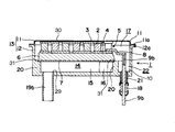
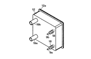
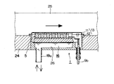
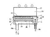
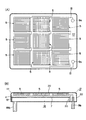
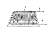
- thermoelectric conversion module of this invention It is a bottom view which shows one Embodiment of the thermoelectric conversion module of this invention. It is a longitudinal cross-sectional view which follows the II-II line of FIG. It is a longitudinal cross-sectional view which follows the III-III line of FIG. It is a longitudinal cross-sectional view which follows the IV-IV line of FIG. It is the perspective view which looked at the external appearance of the lower case which comprises an airtight container from the bottom part. It is the perspective view which looked at the inside of a lower case from the top, (A) mainly represents the flow path of a heat carrier, and (B) represents the relation between the flow path of a heat carrier, and the groove part for electrodes.
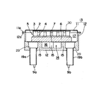
- thermoelectric conversion module which accommodated nine thermoelectric conversion modules in one airtight container
- A is a top view
- B is a center longitudinal cross-sectional view.
- It is a perspective view which shows the exposed thermoelectric conversion module used for the comparison in the experiment which confirms the performance of the package thermoelectric conversion module of this invention.
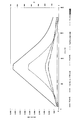
- It is a graph which shows the measurement result of the output of the thermoelectric conversion module of the bare state shown in FIG.
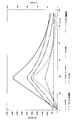
- It is a graph which shows the measurement result of the output at the time of accommodating the module shown in FIG. 13 in an airtight container, and comprising the package thermoelectric conversion module of this invention.
- thermoelectric conversion module 1 to 4 show an embodiment of the thermoelectric conversion module of the present invention.
- the module 5 of the thermoelectric semiconductor 2 is sealed in an airtight container (hereinafter referred to as an airtight container) 13 so that the inside is decompressed or vacuumed.
- the thermoelectric conversion module 5 is generally composed of at least a pair of thermoelectric semiconductors 2, one electrode 3 and the other electrode 4 electrically connected to the thermoelectric semiconductor 2, and the electrodes 3 and 4 are connected in series.
- An electric circuit is formed to conduct from the lead wire 8 at the end to the pair of electrodes 9a and 9b.
- the pair of electrodes 9a and 9b are arranged so as to penetrate the outside of the container 13 from one corner of the hermetic container 13 with the electrical insulator 18 and the hermetic seal 21 interposed between the electrode extraction holes 10 of the hermetic container 13. Is provided. Thereby, the electric power generated by the thermoelectric conversion module 5 can be taken out to the outside of the container 13 while maintaining the hermeticity of the hermetic container 13. In addition, the electric power generated by the thermoelectric conversion module 5 is supplied to the power storage device and the power utilization device via a power recovery line (not shown).
- the airtight container 13 is constituted by an upper case 11 with a flange and a lower case 12 with a flange.
- the interior is integrated in a reduced pressure or vacuum state.
- the inside of the airtight container 13 is divided into at least two chambers of a thermoelectric conversion module storage chamber 17 and a heat medium circulation chamber 14 by a partition plate 7.
- thermoelectric conversion module 5 is accommodated in the thermoelectric conversion module storage chamber 17, and it is provided so that a pressure difference may be produced
- the surface of the upper case 11 facing the thermoelectric conversion module 5 corresponds to a heat receiving plate that transfers heat to one surface of the thermoelectric conversion module 5.
- the joining of the flanges 11a and 12a is not limited to electron beam welding, but can be joined by other welding methods suitable for the case material, brazing material, adhesive, or the like. Moreover, you may make it join the upper case 11 and the lower case 12 which were directly faced without providing the flanges 11a and 12a.
- the pressure inside the hermetic container 13, that is, the pressure in the thermoelectric conversion module storage chamber 17 is lower than the pressure outside the hermetic container 13, for example.
- a vacuum is preferable. Due to the pressure applied to the hermetic container 13 from the outside due to the presence of this differential pressure, the thermoelectric conversion module 5, the upper case 11 and the partition plate 7 are pressed and brought into close contact with each other, and the contact thermal resistance is reduced.
- Patent Document 1 for example, assuming a package thermoelectric conversion module 1 operating at 550 ° C.
- the flexibility and pressure so that at least the surface of the hermetic container 13 facing the thermoelectric conversion module 5 (the other surface of the thermoelectric semiconductor 2) is deformed by the pressure difference inside and outside the container and is pressed against the thermoelectric conversion module 5. It is preferable that it is made of a heat conductive material having rigidity sufficient to ensure airtightness without breaking due to the difference. Therefore, in the case of this embodiment, the upper case 11 is formed of a thin plate made of a material having excellent thermal conductivity. For example, when the thermoelectric conversion module 1 for low temperature is configured using BiTe as the thermoelectric semiconductor 2, the temperature of the heating side of the hermetic container 13, that is, the upper case 11 portion is, for example, about 250 ° C. or less.
- thermoelectric conversion module 1 for high temperature is configured using, for example, FeSi as the thermoelectric semiconductor 2
- the temperature of the heating side of the hermetic container 13, that is, the upper case 11 portion is assumed to be about 600 ° C.
- heat-resistant steel such as Inconel (registered trademark of Special Metals Corporation) can be used.
- a usable material may be selected depending on the use environment.
- the number of thermoelectric conversion modules 5 that can be accommodated in one airtight container 13 is not limited, but it is desirable that the airtight container 13 is nearly square in order for the upper case 11 to be in close contact with each module.
- the material of the upper case 11 is not limited to those exemplified above, and is not necessarily limited to metal, and may be appropriately selected from the viewpoints of heat resistance, corrosion resistance, workability, and the like. Moreover, it is not limited to producing the upper case 11 of an integral product by press molding. For example, in the case of a material that is difficult to be drawn by press molding, the upper surface portion of the upper case 11 facing the thermoelectric conversion module 5 and the peripheral curvature portion (a part of the connecting plate) are formed by press molding. Prepare the other side part, that is, the remaining connecting plate part integrally with the cooling plate or by another member (metal or ceramic), and assemble them by welding or joining methods using brazing material or adhesive Thus, the airtight container 13 may be configured.
- a heat medium circulation chamber 14 in which a flow path 16 through which the heat medium flows is formed, and electrodes 9a and 9b from which the electrodes 3 and 4 of the thermoelectric conversion module 5 are drawn out of the container.
- An electrode groove 22 for placement is provided.
- the heat medium circulation chamber 14 and the electrode groove portion 22 are separated by a weir 20, and the lower case 12 is covered by covering the partition plate 7 so as to be placed on the upper surface of the weir 20 surrounding the heat medium circulation chamber 14.
- a flow path 16 in which the heat medium flows uniformly without unevenness is provided only under a part of the thermoelectric conversion module 5.
- the partition plate 7 is fitted and joined to a receiving seat 31 formed with a step on the upper surface of the weir 20, thereby forming a liquid-tight channel 16 between the partition plate 7 and the lower case 12.
- the partition plate 7 is supported by the receiving seat 31 at the periphery thereof and supported by the plurality of partition walls 15 at the inside.
- the partition plate 7 is directly cooled or heated by a cooling fluid or a heating fluid supplied from an external heat medium supply source (not shown), and the thermoelectric conversion module substrate (hereinafter simply referred to as a substrate) 6 is used for thermoelectric conversion. It is possible to efficiently apply heat to one surface of the conversion module 5.
- the heat medium is not limited to a specific substance, and is usually selected as appropriate from water, oil, refrigerant, and the like. It is possible to realize that the heat medium flows uniformly without unevenness and efficiently applies heat to one surface of the thermoelectric conversion module 5.
- the entire area of the lower case 12 is not used as the heat medium circulation chamber 14, but an electrode groove 22 for taking out and arranging the electrode is provided on one side, and communicates with the space above the partition plate 7.
- a part of the thermoelectric conversion module storage chamber 17 is configured.
- the lower case 12 is formed into a shape shown in the drawing by drawing a thin plate made of a material excellent in coexistence with the heat medium.
- the material of the partition plate 7 and the inlet / outlet pipes 19a and 19b, which are cooling or heating panels, is preferably excellent in coexistence with cooling or heating fluid.
- stainless steel is suitable for water.
- the flow path 16 through which the heat medium flows is raised from the bottom surface of the lower case 12 toward the partition plate 7 and alternately directed from one side of the weir to the other side.
- the groove is formed by a plurality of tortuously formed grooves formed by a plurality of protruding partition walls 15, and an inlet pipe 19 a and an outlet pipe 19 b are formed at both ends of the groove, respectively.
- the heat medium inlet pipe 19a and the outlet pipe 19b are configured by piping joined by brazing or welding to a hole 29 opened in the bottom surface of the lower case 12, and are connected to an external heat medium supply source (not shown). Has been.
- the heat medium circulation chamber 14 is formed with a flow path 16 through which the heat medium is introduced from an external heat medium supply source (not shown) and circulated with the external heat medium supply source, and the partition plate 7 is interposed.
- heat is transferred to one surface of the thermoelectric semiconductor 2 by a heat medium circulating in the flow path 16.
- thermoelectric conversion module 5 may be supported by a substrate 6 having electrical insulation.
- the substrate 6 is, for example, a metal plate, and the electrode 4 is bonded by an electrically insulating bonding material.
- the partition plate 7 and the substrate 6 are in close contact, for example, by bonding with an adhesive or a brazing material, or are in close contact by applying a heat conductive grease.
- a ceramic substrate on which the electrode 4 is deposited can be adopted. Since the substrate 6 is formed using an electrically insulating ceramic, an electrically insulating bonding material is not required between the substrate 6 and the electrode 4.
- a product obtained by evaporating copper in the shape of an electrode on an alumina plate is available as DBC (Direct Bonding Copper), which can be used as the substrate 6 and the electrode 4.
- DBC Direct Bonding Copper
- the partition plate 7 and the substrate 6 are bonded and adhered, for example, by bonding or brazing.
- the substrate 6 made of the present ceramic can also serve as the partition plate 7, and this may be bonded to the case 20 with a metal / ceramic adhesive.
- thermoelectric conversion module 5 can employ a double-sided skeleton type module (not shown) having no substrate on both the upper and lower surfaces.
- a double-sided skeleton type module (not shown) having no substrate on both the upper and lower surfaces.
- the electrode 4 since the electrode 4 is exposed, it is necessary to perform electrical insulation by inserting a thin sheet of electrical insulation and heat resistance such as mica and a polymer sheet into the upper and lower surfaces of the module.
- the contact thermal resistance can be reduced by applying and thermally adhering heat conductive grease to one or both sides of the electrically insulating and heat resistant sheet.
- a sliding material 30 having thermal conductivity is interposed between the surface of the upper case 11 of the package thermoelectric conversion system 1 facing the thermoelectric conversion module 5 and the electrode plate 3.
- the thermal conduction between the upper case 11 and the electrode 3 is facilitated by the intervention of the heat conductive sliding material 30 and the relative sliding or deviation between the upper case 11 and the electrode 3 is facilitated.
- the sliding material 30 has at least thermal conductivity and slidability (sliding), but more preferably has electrical insulation.
- an electrical insulating material or an electrical insulating layer is interposed between the electrode portion 3 and the sliding material 30, the sliding material 30 itself does not need to have electrical insulation.
- a viscous material such as a low friction coefficient sheet material having thermal conductivity or grease
- a carbon sheet or a polymer sheet as the sheet material.
- the carbon sheet is excellent in slidability, heat conductivity and heat resistance, so that it is possible to use a thermoelectric semiconductor at a higher maximum operating temperature and there is no thermal resistance at the interface where the carbon sheet is interposed. It can be reduced to 1/10 or less of the case.
- combined use with a mica sheet can ensure electrical insulation and can improve heat conduction and sliding at the interface. In particular, when used in an airtight container, it can be used at a higher temperature than when used in the atmosphere.
- the polymer sheet is excellent in slidability and electrically insulating, it can be brought into direct contact with the electrode material. Furthermore, when grease, which is a viscous material, is interposed between the upper case 11 and the electrode 3 as a sliding material, shear stress is prevented from occurring, and since the viscous material is used, there is no gap between the heating plate and the electrode portion. The contact thermal resistance at the interface can be reduced by closely contacting. Thereby, a large temperature difference can be loaded on the thermoelectric semiconductor.
- the airtight container 13 receives a pressing force from the outside due to the differential pressure inside and outside the container.
- the surface facing the thermoelectric conversion module 5 of the upper case 11 of the airtight container 13 is uniformly pressed against the thermoelectric conversion module 5 using this pressing force.
- the heat received by the upper case 11 of the hermetic container is uniformly transferred to the thermoelectric conversion module 5.
- the heat of the heat medium flowing through the flow path 16 in the hermetic container 13 is efficiently transferred to the lower surface of the thermoelectric conversion module 5 through the partition plate 7 and the substrate 6. Therefore, even if an external force is not applied to the package thermoelectric conversion module 1 using a pressure mechanism, a temperature difference is appropriately given to the thermoelectric conversion module 5.
- thermoelectric semiconductor 2 is interposed between the upper case 11 portion of the hermetic container 13 and the electrode 3, for example, even if the hermetic container 13 is thermally expanded, the upper case 11 portion of the hermetic container 13 is moved to the sliding material 30. Therefore, a large shear stress does not act on the thermoelectric semiconductor 2, the electrode 3, and the electrode 4. Therefore, even if the package thermoelectric conversion module 1 is increased in size, the fragile thermoelectric semiconductor 2 is not broken or peeled off at the joint surface.
- the interface where the sheet material or the grease is interposed is pressurized from the outside of the airtight container 13 by the differential pressure inside and outside the airtight container 13, the contact thermal resistance at the interface can be reduced due to good adhesion. Thereby, a large temperature difference can be given to the thermoelectric semiconductor 2.
- thermoelectric conversion module 1 since it becomes possible to enlarge the thermoelectric conversion module 1 by setting it as the structure which accept
- the package thermoelectric conversion module 1 configured as described above can be used for various purposes.
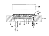
- the cooling fluid 26 is circulated through the flow path 16 inside the hermetic container 13, while the outside of the upper surface of the upper case 11 (the surface with which the upper side of the thermoelectric conversion module 5 contacts) is a radiant heat source 23. It is possible to heat.
- the lower case 12 portion of the hermetic container 13 is surrounded by the heat insulating material 24 so that only the upper case 11 is exposed to the radiant heat source 23.
- FIG. 8 it is also possible to generate electricity by circulating a cooling fluid 26 through a flow path 16 inside the hermetic container 13 and flowing a heating fluid 25 around and outside the upper case 11.
- FIG. 9 it is also possible to generate power by circulating a heating fluid 25 through a flow path 16 inside the hermetic container 13 and flowing a cooling fluid 26 around and outside the upper case 11.
- the cooling fluid 26 is circulated through the flow path 16 inside the hermetic container 13, the heating duct 27 is brought into pressure contact with the outside and the outside of the upper case 11, and the heating fluid is placed in the heating duct 27.
- heat by flowing 25 it is also possible to heat by flowing 25.
- the heating fluid 25 is circulated through the flow path 16 inside the hermetic container 13, the cooling duct 28 is brought into pressure contact with the outside and the outside of the upper case 11, and the cooling duct 28 is cooled. It is also possible to cool by flowing the fluid 26.
- thermoelectric conversion module 1 of the present invention is provided so that the cooling fluid 26 or the heating fluid 25 flows in the hermetic container 13. Therefore, the package thermoelectric conversion module 1 can be simply disposed in any environment. It can be used.
- thermoelectric conversion modules 5 housed in the airtight container 13 can be provided.
- nine thermoelectric conversion modules 5 may be accommodated and connected in series with each other.
- one thermoelectric conversion module 5 has a side of about 4 cm square, and even a large one is about 6 cm square.
- the price of the airtight container itself is not nine times cheaper, so the unit cost per module output can be reduced.
- the modules can be arranged close to each other, the module installation density per unit area can be increased as compared with the case where the modules are housed in the airtight container 13 one by one.
- thermoelectric conversion module of the present invention was compared with the exposed thermoelectric conversion module of FIG. 13 that is not housed in an airtight container.
- symbol is attached
- thermoelectric conversion module 5 for low temperature shown in FIG. 13 was configured using 4 mm square BiTe as the thermoelectric semiconductor 2. Then, the output was measured when a high temperature side of the module was 150 ° C., a low temperature side was 20 ° C., and a temperature difference of 130 K was applied. The result is shown in FIG. From this result, it was confirmed that an output of 3.2 W was obtained.
- thermoelectric conversion module having the structure shown in FIG. 13 was accommodated in the hermetic container 13, and the package thermoelectric conversion module 1 for low temperature having a sealed structure as shown in FIG. 12 was configured.
- the result is shown in FIG.
- the output is 25% lower than the measurement result of the comparative example shown in FIG.
- V Cooling water flow velocity (cm / s)
- the above-described embodiment is an example of a preferred embodiment of the present invention, but is not limited thereto, and various modifications can be made without departing from the gist of the present invention.
- one or both of the electrodes 9a and 9b and the heat medium inlet / outlet pipes 19a and 19b can be installed on the side surface instead of the bottom surface of the lower case 12.
- the electrodes 9a and 9b are installed on the side surface of the lower case 12, the entire lower case 12 is divided into two layers by the partition plate 7, and the thermoelectric conversion module 5 and the electrodes 9a and 9b are formed on the upper layer of the partition plate 7. Is formed, and a flow path 16 through which a cooling or heating heat medium flows can be formed in the entire layer below the partition plate 7.
- the present invention utilizes a waste heat radiated from a heated part inside or outside an industrial furnace such as a powder metallurgy sintering furnace or various electric furnaces, which is heated by radiation from a high-temperature heat source.
- thermoelectric conversion module 2 Thermoelectric semiconductor 3
- One electrode 4 The other electrode 5
- Thermoelectric conversion module 6 Thermoelectric conversion module board 7 Partition plate (heat transfer panel) 9a, 9b Electrode 11 Upper case 12 Lower case 13 Airtight container 14 Heat medium circulation chamber 16 Flow path 17 through which the heat medium circulates Thermoelectric conversion module storage chambers 19a, 19b Heat medium inlet / outlet (pipe) connected to a heat medium supply source (not shown) )
Landscapes
- Cooling Or The Like Of Semiconductors Or Solid State Devices (AREA)
Abstract
L'invention concerne un module de conversion thermoélectrique sous boîtier dans lequel un mécanisme de mise sous pression ou un revêtement ayant une graisse thermoconductrice pour réduire la résistance de contact thermique ne sont pas nécessaires entre le module de conversion thermoélectrique scellé dans un conteneur étanche à l'air et une source de chaleur. Dans le module de conversion thermoélectrique sous boîtier (1), dans lequel l'intérieur du conteneur étanche à l'air (13) recevant le module de conversion thermoélectrique (5) est sous pression négative ou sous vide, l'intérieur du conteneur étanche à l'air (13) est divisé par une plaque de cloisonnement (7) en deux chambres (14, 17). Une des chambres (17) comprend le module de conversion thermoélectrique (5) et des électrodes (9a, 9b) menant à l'extérieur du boîtier étanche à l'air (13), tandis qu'un trajet d'écoulement (16) pour introduire un milieu chauffant (26 ou 25) depuis une source d'alimentation en milieu chauffant externe et pour faire circuler le milieu chauffant entre la chambre (14) et la source d'alimentation en milieu chauffant externe est formé dans l'autre chambre (14). Lors du transfert de chaleur à une des surfaces des semi-conducteurs thermoélectriques (2) à l'aide du milieu chauffant (25 ou 26) et par le biais de la plaque de cloisonnement (7), la chaleur est transférée entre les autres surfaces des semi-conducteurs thermoélectriques (2) et la source de chaleur externe par l'intermédiaire du conteneur étanche à l'air (13).
Priority Applications (3)
| Application Number | Priority Date | Filing Date | Title |
|---|---|---|---|
| US13/144,539 US20110265838A1 (en) | 2009-01-21 | 2010-01-14 | Packaged thermoelectric conversion module |
| EP10733326A EP2383809A1 (fr) | 2009-01-21 | 2010-01-14 | Module de conversion thermoélectrique sous boîtier |
| JP2010547427A JP5432927B2 (ja) | 2009-01-21 | 2010-01-14 | パッケージ熱電変換モジュール |
Applications Claiming Priority (2)
| Application Number | Priority Date | Filing Date | Title |
|---|---|---|---|
| JP2009-011006 | 2009-01-21 | ||
| JP2009011006 | 2009-01-21 |
Publications (1)
| Publication Number | Publication Date |
|---|---|
| WO2010084718A1 true WO2010084718A1 (fr) | 2010-07-29 |
Family
ID=42355776
Family Applications (1)
| Application Number | Title | Priority Date | Filing Date |
|---|---|---|---|
| PCT/JP2010/000185 WO2010084718A1 (fr) | 2009-01-21 | 2010-01-14 | Module de conversion thermoélectrique sous boîtier |
Country Status (4)
| Country | Link |
|---|---|
| US (1) | US20110265838A1 (fr) |
| EP (1) | EP2383809A1 (fr) |
| JP (1) | JP5432927B2 (fr) |
| WO (1) | WO2010084718A1 (fr) |
Cited By (11)
| Publication number | Priority date | Publication date | Assignee | Title |
|---|---|---|---|---|
| JP2014049713A (ja) * | 2012-09-04 | 2014-03-17 | Hitachi Chemical Co Ltd | 熱電変換モジュールおよびその製造方法 |
| JP2014075959A (ja) * | 2012-10-05 | 2014-04-24 | Hitachi Chemical Co Ltd | 熱電変換式発電装置 |
| JP2014212590A (ja) * | 2013-04-17 | 2014-11-13 | 日立化成株式会社 | 熱電変換式発電装置 |
| JP2015520836A (ja) * | 2012-04-13 | 2015-07-23 | エーバーシュペッヒャー・エグゾースト・テクノロジー・ゲーエムベーハー・ウント・コンパニー・カーゲー | 熱電発電機を備えた熱交換機 |
| JP2016116363A (ja) * | 2014-12-16 | 2016-06-23 | ヤンマー株式会社 | 熱電発電ユニット、それを用いた熱電発電装置およびその取付構造、その取付構造を有する排気ダクトならびにエンジン |
| JP2017060305A (ja) * | 2015-09-16 | 2017-03-23 | 株式会社デンソー | 熱電発電装置 |
| JP2017059821A (ja) * | 2015-09-16 | 2017-03-23 | 株式会社デンソー | 熱電発電装置及びその製造方法 |
| WO2017047562A1 (fr) * | 2015-09-16 | 2017-03-23 | 株式会社デンソー | Dispositif de production d'énergie thermoélectrique et procédé de fabrication correspondant |
| KR102150308B1 (ko) * | 2019-04-02 | 2020-09-01 | 엘지전자 주식회사 | 열전발전모듈 |
| WO2021145621A1 (fr) * | 2020-01-13 | 2021-07-22 | 엘지이노텍 주식회사 | Appareil de production d'énergie |
| WO2022060026A1 (fr) * | 2020-09-17 | 2022-03-24 | 엘지이노텍 주식회사 | Module thermoélectrique et dispositif générateur d'énergie le comportant |
Families Citing this family (11)
| Publication number | Priority date | Publication date | Assignee | Title |
|---|---|---|---|---|
| CN104685646A (zh) * | 2012-10-05 | 2015-06-03 | 日立化成株式会社 | 热电变换式发电装置 |
| DE102012222635A1 (de) * | 2012-12-10 | 2014-06-12 | Behr Gmbh & Co. Kg | Wärmeübertrager, insbesondere für ein Kraftfahrzeug |
| CA2906160C (fr) | 2013-03-15 | 2021-10-19 | Vecarius, Inc. | Dispositif thermoelectrique |
| US20160247996A1 (en) * | 2015-02-19 | 2016-08-25 | Novus Energy Technologies, Inc. | Large footprint, high power density thermoelectric modules for high temperature applications |
| KR20160129637A (ko) * | 2015-04-30 | 2016-11-09 | 엘지이노텍 주식회사 | 열전모듈 및 이를 포함하는 열전환장치 |
| KR101827120B1 (ko) * | 2016-05-30 | 2018-02-07 | 현대자동차주식회사 | 열전모듈용 하우징 |
| DE102016209683A1 (de) * | 2016-06-02 | 2017-12-07 | Mahle International Gmbh | Thermoelektrisches Modul |
| KR101846685B1 (ko) | 2016-07-11 | 2018-05-18 | 현대자동차주식회사 | 열전모듈 패키징방법 |
| CN110447166B (zh) * | 2017-04-10 | 2022-03-29 | 株式会社村田制作所 | 热电变换元件模块 |
| US20190041104A1 (en) * | 2017-08-07 | 2019-02-07 | Asia Vital Components Co., Ltd. | Heat exchange structure of heat dissipation device |
| JP2021125645A (ja) * | 2020-02-07 | 2021-08-30 | 三菱マテリアル株式会社 | 熱電変換構造体 |
Citations (5)
| Publication number | Priority date | Publication date | Assignee | Title |
|---|---|---|---|---|
| JPH0918059A (ja) * | 1995-06-28 | 1997-01-17 | Technova:Kk | 熱電変換装置 |
| JP2002100816A (ja) * | 2000-09-22 | 2002-04-05 | Matsushita Refrig Co Ltd | 熱電冷却装置 |
| JP2006049872A (ja) | 2004-07-06 | 2006-02-16 | Central Res Inst Of Electric Power Ind | 熱電変換モジュール |
| JP2006066431A (ja) * | 2004-08-24 | 2006-03-09 | Toshiba Corp | 熱−電気直接変換装置 |
| JP2007311656A (ja) * | 2006-05-19 | 2007-11-29 | Toyota Motor Corp | 熱電モジュール |
-
2010
- 2010-01-14 EP EP10733326A patent/EP2383809A1/fr not_active Withdrawn
- 2010-01-14 WO PCT/JP2010/000185 patent/WO2010084718A1/fr active Application Filing
- 2010-01-14 JP JP2010547427A patent/JP5432927B2/ja not_active Expired - Fee Related
- 2010-01-14 US US13/144,539 patent/US20110265838A1/en not_active Abandoned
Patent Citations (5)
| Publication number | Priority date | Publication date | Assignee | Title |
|---|---|---|---|---|
| JPH0918059A (ja) * | 1995-06-28 | 1997-01-17 | Technova:Kk | 熱電変換装置 |
| JP2002100816A (ja) * | 2000-09-22 | 2002-04-05 | Matsushita Refrig Co Ltd | 熱電冷却装置 |
| JP2006049872A (ja) | 2004-07-06 | 2006-02-16 | Central Res Inst Of Electric Power Ind | 熱電変換モジュール |
| JP2006066431A (ja) * | 2004-08-24 | 2006-03-09 | Toshiba Corp | 熱−電気直接変換装置 |
| JP2007311656A (ja) * | 2006-05-19 | 2007-11-29 | Toyota Motor Corp | 熱電モジュール |
Cited By (19)
| Publication number | Priority date | Publication date | Assignee | Title |
|---|---|---|---|---|
| JP2015520836A (ja) * | 2012-04-13 | 2015-07-23 | エーバーシュペッヒャー・エグゾースト・テクノロジー・ゲーエムベーハー・ウント・コンパニー・カーゲー | 熱電発電機を備えた熱交換機 |
| JP2014049713A (ja) * | 2012-09-04 | 2014-03-17 | Hitachi Chemical Co Ltd | 熱電変換モジュールおよびその製造方法 |
| JP2014075959A (ja) * | 2012-10-05 | 2014-04-24 | Hitachi Chemical Co Ltd | 熱電変換式発電装置 |
| JP2014212590A (ja) * | 2013-04-17 | 2014-11-13 | 日立化成株式会社 | 熱電変換式発電装置 |
| JP2016116363A (ja) * | 2014-12-16 | 2016-06-23 | ヤンマー株式会社 | 熱電発電ユニット、それを用いた熱電発電装置およびその取付構造、その取付構造を有する排気ダクトならびにエンジン |
| WO2016098679A1 (fr) * | 2014-12-16 | 2016-06-23 | ヤンマー株式会社 | Unité de génération thermoélectrique, dispositif de génération thermoélectrique l'utilisant et sa structure de montage, conduit d'échappement ayant la même structure de montage et moteur |
| US10557395B2 (en) | 2014-12-16 | 2020-02-11 | Yanmar Co., Ltd | Thermoelectric generating unit, thermoelectric generator using the thermoelectric generating unit, mounting structure of the thermoelectric generator, and exhaust duct and engine including the mounting structure |
| WO2017047563A1 (fr) * | 2015-09-16 | 2017-03-23 | 株式会社デンソー | Dispositif de production d'énergie thermoélectrique |
| JP2017059821A (ja) * | 2015-09-16 | 2017-03-23 | 株式会社デンソー | 熱電発電装置及びその製造方法 |
| WO2017047562A1 (fr) * | 2015-09-16 | 2017-03-23 | 株式会社デンソー | Dispositif de production d'énergie thermoélectrique et procédé de fabrication correspondant |
| EP3352366A4 (fr) * | 2015-09-16 | 2018-11-07 | Denso Corporation | Dispositif de production d'énergie thermoélectrique et procédé de fabrication correspondant |
| JP2017060305A (ja) * | 2015-09-16 | 2017-03-23 | 株式会社デンソー | 熱電発電装置 |
| US10629794B2 (en) | 2015-09-16 | 2020-04-21 | Denso Corporation | Thermoelectric power generation device and method for manufacturing same |
| US11024787B2 (en) | 2015-09-16 | 2021-06-01 | Denso Corporation | Thermoelectric power generation device |
| KR102150308B1 (ko) * | 2019-04-02 | 2020-09-01 | 엘지전자 주식회사 | 열전발전모듈 |
| WO2020204446A1 (fr) * | 2019-04-02 | 2020-10-08 | 엘지전자 주식회사 | Module de production d'énergie thermoélectrique |
| WO2021145621A1 (fr) * | 2020-01-13 | 2021-07-22 | 엘지이노텍 주식회사 | Appareil de production d'énergie |
| EP4092770A4 (fr) * | 2020-01-13 | 2023-12-27 | LG Innotek Co., Ltd. | Appareil de production d'énergie |
| WO2022060026A1 (fr) * | 2020-09-17 | 2022-03-24 | 엘지이노텍 주식회사 | Module thermoélectrique et dispositif générateur d'énergie le comportant |
Also Published As
| Publication number | Publication date |
|---|---|
| US20110265838A1 (en) | 2011-11-03 |
| JPWO2010084718A1 (ja) | 2012-07-12 |
| EP2383809A1 (fr) | 2011-11-02 |
| JP5432927B2 (ja) | 2014-03-05 |
Similar Documents
| Publication | Publication Date | Title |
|---|---|---|
| JP5432927B2 (ja) | パッケージ熱電変換モジュール | |
| JP5642419B2 (ja) | 気密ケース入り熱電変換モジュール | |
| JP4829552B2 (ja) | 熱電変換モジュール | |
| CN107017214B (zh) | 被冷却的电力电子组件 | |
| EP1615274A2 (fr) | Module de conversion thermoélectrique | |
| JP5999665B2 (ja) | 熱移動ユニットおよび温度調節装置 | |
| JP2004350479A (ja) | 熱電変換発電ユニットおよびこの熱電変換発電ユニットを備えるトンネル型炉 | |
| JP2006049872A5 (fr) | ||
| KR20180055696A (ko) | 종합성능이 양호한 방열구조부재 및 그 제조 공정 | |
| TWI259828B (en) | Ozonizer | |
| CN109152311A (zh) | 一种新型散热电路板 | |
| WO2010090350A1 (fr) | Générateur électrique | |
| JP5970222B2 (ja) | 熱電発電装置 | |
| EP2539945B1 (fr) | Procédé et appareil à écart submicronique à grande échelle pour technique thermo-photovoltaïque à écart micronique | |
| JP2006024608A (ja) | 伝熱用クッションおよびこれを備える熱電変換モジュール | |
| JP2013211471A (ja) | 熱電発電装置 | |
| CN111586901B (zh) | 电加热装置 | |
| Kambe et al. | Encapsulated thermoelectric modules for advanced thermoelectric systems | |
| JP5049533B2 (ja) | 熱電変換装置 | |
| JP2017063091A (ja) | 熱電変換システム | |
| NL2012372C2 (en) | Spring-loaded heat exchanger fins. | |
| JP2013232500A (ja) | 熱電変換モジュールの評価装置 | |
| RU2230397C1 (ru) | Термоэлектрическая батарея | |
| JP2000124509A (ja) | 熱電モジュールジャケット、熱電加熱冷却装置、熱電モジュールジャケットの製造方法、及び熱電加熱冷却装置の製造方法 | |
| RU2736734C1 (ru) | Термоэлектрическая батарея. |
Legal Events
| Date | Code | Title | Description |
|---|---|---|---|
| 121 | Ep: the epo has been informed by wipo that ep was designated in this application |
Ref document number: 10733326 Country of ref document: EP Kind code of ref document: A1 |
|
| WWE | Wipo information: entry into national phase |
Ref document number: 2010547427 Country of ref document: JP |
|
| WWE | Wipo information: entry into national phase |
Ref document number: 13144539 Country of ref document: US |
|
| NENP | Non-entry into the national phase |
Ref country code: DE |
|
| WWE | Wipo information: entry into national phase |
Ref document number: 2010733326 Country of ref document: EP |