WO2010079652A1 - 工作機械の工具洗浄装置 - Google Patents
工作機械の工具洗浄装置 Download PDFInfo
- Publication number
- WO2010079652A1 WO2010079652A1 PCT/JP2009/069336 JP2009069336W WO2010079652A1 WO 2010079652 A1 WO2010079652 A1 WO 2010079652A1 JP 2009069336 W JP2009069336 W JP 2009069336W WO 2010079652 A1 WO2010079652 A1 WO 2010079652A1
- Authority
- WO
- WIPO (PCT)
- Prior art keywords
- tool
- cleaning
- foreign matter
- cleaning device
- machine
- Prior art date
Links
Images

Classifications
-
- B—PERFORMING OPERATIONS; TRANSPORTING
- B23—MACHINE TOOLS; METAL-WORKING NOT OTHERWISE PROVIDED FOR
- B23Q—DETAILS, COMPONENTS, OR ACCESSORIES FOR MACHINE TOOLS, e.g. ARRANGEMENTS FOR COPYING OR CONTROLLING; MACHINE TOOLS IN GENERAL CHARACTERISED BY THE CONSTRUCTION OF PARTICULAR DETAILS OR COMPONENTS; COMBINATIONS OR ASSOCIATIONS OF METAL-WORKING MACHINES, NOT DIRECTED TO A PARTICULAR RESULT
- B23Q17/00—Arrangements for observing, indicating or measuring on machine tools
- B23Q17/24—Arrangements for observing, indicating or measuring on machine tools using optics or electromagnetic waves
- B23Q17/2452—Arrangements for observing, indicating or measuring on machine tools using optics or electromagnetic waves for measuring features or for detecting a condition of machine parts, tools or workpieces
- B23Q17/2457—Arrangements for observing, indicating or measuring on machine tools using optics or electromagnetic waves for measuring features or for detecting a condition of machine parts, tools or workpieces of tools
-
- B—PERFORMING OPERATIONS; TRANSPORTING
- B23—MACHINE TOOLS; METAL-WORKING NOT OTHERWISE PROVIDED FOR
- B23Q—DETAILS, COMPONENTS, OR ACCESSORIES FOR MACHINE TOOLS, e.g. ARRANGEMENTS FOR COPYING OR CONTROLLING; MACHINE TOOLS IN GENERAL CHARACTERISED BY THE CONSTRUCTION OF PARTICULAR DETAILS OR COMPONENTS; COMBINATIONS OR ASSOCIATIONS OF METAL-WORKING MACHINES, NOT DIRECTED TO A PARTICULAR RESULT
- B23Q17/00—Arrangements for observing, indicating or measuring on machine tools
- B23Q17/09—Arrangements for observing, indicating or measuring on machine tools for indicating or measuring cutting pressure or for determining cutting-tool condition, e.g. cutting ability, load on tool
- B23Q17/0904—Arrangements for observing, indicating or measuring on machine tools for indicating or measuring cutting pressure or for determining cutting-tool condition, e.g. cutting ability, load on tool before or after machining
- B23Q17/0914—Arrangements for measuring or adjusting cutting-tool geometry machine tools
-
- B—PERFORMING OPERATIONS; TRANSPORTING
- B23—MACHINE TOOLS; METAL-WORKING NOT OTHERWISE PROVIDED FOR
- B23Q—DETAILS, COMPONENTS, OR ACCESSORIES FOR MACHINE TOOLS, e.g. ARRANGEMENTS FOR COPYING OR CONTROLLING; MACHINE TOOLS IN GENERAL CHARACTERISED BY THE CONSTRUCTION OF PARTICULAR DETAILS OR COMPONENTS; COMBINATIONS OR ASSOCIATIONS OF METAL-WORKING MACHINES, NOT DIRECTED TO A PARTICULAR RESULT
- B23Q17/00—Arrangements for observing, indicating or measuring on machine tools
- B23Q17/24—Arrangements for observing, indicating or measuring on machine tools using optics or electromagnetic waves
- B23Q17/2409—Arrangements for indirect observation of the working space using image recording means, e.g. a camera
Definitions
- the present invention relates to a tool cleaning device for a machine tool that removes foreign matter adhering to the tool before measuring the dimension of the tool of the machine tool.
- the tool dimensions (tool length, tool diameter, etc.) are measured before machining the workpiece, and the tool wear and the like are corrected based on the measurement results. Processing accuracy is obtained by processing the workpiece.
- Non-contact type measuring devices have been used.
- Patent Document 1 in the measurement of the tool length by a laser measuring device, the tool is cleaned by spraying a degreasing cleaner on the tool to remove the oil film adhering to the tool, and then the tool dimension is measured by laser.
- a technique is disclosed in which measurement error is reduced by measuring with a measuring instrument.
- an object of the present invention is to provide a tool cleaning device for a machine tool that can reliably remove foreign matter adhering to the tool.
- a tool cleaning device for a machine tool for solving the above-mentioned problems is a tool cleaning device for a machine tool that removes foreign matter adhering to the tool before measuring the dimension of the tool, An imaging means for imaging the tip of the tool from the side, a tool cleaning means for cleaning the tool by spraying a cleaning agent toward the tool, and a foreign object on the tool based on an image captured by the imaging means Control means for determining whether or not the foreign matter is attached and controlling the tool cleaning means based on whether or not the foreign matter is attached.
- a tool cleaning device for a machine tool according to a second invention is characterized in that in the tool cleaning device for a machine tool according to the first invention, a display means for displaying an image captured by the imaging means is provided. .
- a tool cleaning device for a machine tool according to a third invention is the tool cleaning device for a machine tool according to the first or second invention, wherein the control means applies the tool to the tool based on a preset tool shape. It is characterized by determining the presence or absence of adhered foreign matter.
- a tool cleaning device for a machine tool according to a fourth aspect of the present invention is the tool cleaning device for a machine tool according to the third aspect of the present invention, wherein the control means Control is performed.
- a tool cleaning device for a machine tool according to a fifth invention is the tool cleaning device for a machine tool according to the fourth invention, wherein the control means determines that the cleaning of the tool by the tool cleaning means is the maximum number of times of cleaning. It is characterized by giving a warning when exceeding.
- a tool cleaning device for a machine tool according to a sixth invention is the tool cleaning device for a machine tool according to the first invention, wherein the control means determines that no foreign matter adheres to the tool. The dimensions of the tool are measured.
- the tool cleaning device for a machine tool removes foreign matter adhering to the tool before measuring the tool size, and the tip of the tool is moved to the side.
- An image pickup means for picking up an image from the direction
- a tool cleaning means for cleaning the tool by spraying a cleaning agent toward the tool, and determining whether foreign matter is attached to the tool based on an image picked up by the image pickup means
- a control means for controlling the tool cleaning means on the basis of the presence or absence of foreign matter, so that unnecessary cleaning is performed on a tool on which no foreign matter is attached, or the tool is removed without foreign matter being removed. There is no fear of ending cleaning, and the tool can be optimally cleaned without excess or deficiency.
- the display means for displaying the image picked up by the image pickup means is provided, it is possible to visually recognize the foreign matter adhering to the tool, which is convenient. improves.
- the control means determines the presence or absence of foreign matter attached to the tool based on a preset tool shape. It is possible to detect whether or not there is high accuracy.
- the control means controls the tool cleaning means based on the preset maximum number of times of cleaning, so even if the tool is cleaned a plurality of times. When foreign matter that cannot be removed is adhered or when some abnormality occurs, it is possible to prevent excessive cleaning.
- the control means warns when the cleaning of the tool by the tool cleaning means exceeds the maximum number of times of cleaning, so that the abnormality can be recognized quickly. Can do.
- the control means measures the size of the tool when it is determined that no foreign matter is attached to the tool. It is possible to measure the dimensions of the tool after confirming that it is not, and the measurement accuracy is improved.
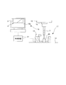
- FIG. 1 is an explanatory view showing an example in which a tool cleaning device for a machine tool according to an embodiment of the present invention is applied to a machine tool
- FIG. 2 is a schematic view showing an embodiment of a tool size measuring device for a machine tool according to the present invention.
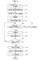
- FIG. 3 is a flowchart showing the procedure for measuring the tool length by the tool cleaning device for a machine tool according to this embodiment.
- a workpiece is placed on a bed 11 constituting a base of the machine tool 1 via a table 12.
- the tool 3 is supported via the column 13, the saddle 14, the spindle head 15, and the spindle 16.
- the bed 11 has a guide surface on its upper surface, and supports the table 12 movably back and forth along the guide surface.
- a workpiece 2 is fixed on the upper surface of the table 12, and a tool dimension measuring device 17 having a function as a tool cleaning device is installed at one corner thereof.
- the tool dimension measuring device 17 is a device for measuring the tool length of the tool 3, and as shown in FIG. 2, a CCD camera 18 as an imaging unit, a display unit 19 as a display unit, and a tool as a cleaning unit. And a cleaning unit 20.
- the CCD camera 18, the display unit 19, and the tool cleaning unit 20 constituting the tool dimension measuring device 17 are connected to a control device 21 as control means.
- the CCD camera 18 continuously images the tip of the tool 3 at a certain time interval from the side thereof, that is, the position facing the peripheral surface of the tool 3, and outputs the acquired image data to the control device 21.
- the display unit 19 displays the image data input from the CCD camera 18 to the control device 21 on the display screen 19a.
- the tool cleaning unit 20 cleans the tool 3 by injecting a cleaning agent onto the tool 3 based on a command from the control device 21. In this embodiment, a water-based cleaning agent is used.
- the control device 21 controls the table 12, the saddle 14, the spindle head 15, and the spindle 16 when measuring the dimensions of the tool 3 and processing the workpiece 2. Further, the image data input from the CCD camera 18 is subjected to image processing, and the presence / absence of foreign matter adhering to the tool 3 is determined. Then, the drive control of the tool cleaning unit 20 is performed based on the presence or absence of foreign matter adhering to the tool 3, and the tool length, the tool diameter, and the like of the tool are processed by image processing based on the image data input from the CCD camera 18. Calculate the dimensions.
- the column 13 is placed on the bed 11 and has a guide surface on the front surface thereof, and supports the saddle 14 so as to be horizontally movable along the guide surface.
- the saddle 14 has a guide surface on the front surface thereof, and supports the spindle head 15 so as to be movable up and down along the guide surface.
- the spindle head 15 supports the spindle 16 so as to be rotatable about an axis parallel to the vertical direction.
- the tool 3 is attached to the tip of the main shaft 16 so as to be rotatable and detachable integrally with the main shaft 16.
- step P1 the shapes of various tools are stored in advance as a database (step P2).
- the shape of the tool 3 used for machining is selected from the tool shapes previously stored in the database in Step P1, and set as a reference shape.
- a maximum value of the number of times of tool cleaning performed for one tool 3 is set as the maximum number of times of cleaning (step P2).
- the tool 3 is mounted on the spindle 16 by exchanging the tool (step P3), and the spindle 16 is rotated (step P4).
- the table 12, the saddle 14 and the spindle head 15 are controlled so that the tool 3 is measured by the tool size measuring device 17, that is, directly above the tool size measuring device 17, and the tip of the tool 3 is moved by the CCD camera 18. It is moved to a position where it can be imaged (position shown in FIG. 2) (step P5).
- step P6 it is determined whether or not the number of times the tool 3 has been cleaned by the tool cleaning unit 20 is within the maximum number of times set in step P2 (step P6). If the result of determination is that the number of cleanings for the tool 3 is within the maximum number of cleanings (YES), the tool cleaning unit 20 is controlled to spray a cleaning agent on the tool 3 to clean the tool 3 (step P7). On the other hand, if the result of determination in step P6 is that the number of cleanings for the tool 3 is greater than the maximum number of cleanings (NO), it is determined that some abnormality has occurred, such as the foreign matter cannot be completely removed by cleaning with the tool cleaning unit 20, and an alarm is generated. Then, the machine is stopped (step P13).
- Step P7 the CCD camera 18 images the tip of the tool 3, performs image processing on the obtained image, and extracts the shape of the object imaged in the image as tool measurement (Step P8). ). Thereafter, the shape of the object extracted from the image is compared with the reference shape set in step P2, and the presence or absence of foreign matter attached to the tool 3 is determined (step P9).
- Step P10 If it is determined that no foreign matter is attached to the tool 3 as a result of the determination (YES), the tool length, tool diameter, and other dimensions of the tool 3 are calculated based on the image captured by the CCD camera 18. (Step P10). On the other hand, when it is determined that foreign matter is attached to the tool 3 (NO), the process returns to Step P6.
- step P10 When the process of step P10 is completed, the table 12, the saddle 14 and the spindle head 15 are controlled to move the tool 3 to the workpiece machining position (for example, the position shown in FIG. 1) (step P11). Processing is started (step P12).
- the registration of the database in step P1 does not have to be performed every time the dimensions of the tool 3 are measured, but may be set as necessary.
- an example is shown in which the machine is stopped as an alarm in Step P13 when the foreign matter cannot be removed within the maximum number of times of cleaning.
- the alarm is not limited to the stop of the machine. Needless to say, various changes can be made without departing from the spirit of the present invention, such as issuing an alarm.
- the maximum number of times of cleaning for example, it is more preferable to set the number of times so that the tool can be cleaned using the time until the thermal displacement of the tool is stabilized.
- the measurement of the dimensions of the tool may be performed as needed, for example, when the tool 3 is mounted on the spindle 16 by exchanging the tool 3 or when each workpiece 2 is processed. .
- the tool cleaning device for a machine tool it can be confirmed whether or not the foreign matter 4 attached to the tool 3 has been reliably removed. Therefore, the tool 3 can be cleaned efficiently without fear of excessive cleaning or termination of the cleaning of the tool 3 in a state where the foreign matter 4 is not removed.
- the dimension of the tool 3 can be measured after confirming the presence or absence of the foreign matter 4 attached to the tool 3, the measurement error can be prevented and the dimension of the tool 3 can be measured with high accuracy. Moreover, when the foreign material 4 has adhered to the tool 3, as shown in FIG. 2, this foreign material 4 can be visually recognized on the display screen 19a, and the convenience improves.
- the cleaning agent scatters due to the rotation of the tool after cleaning, so that it does not adhere to the tool and does not affect the measurement of the tool dimensions. It was confirmed.
- the present invention can be applied to a tool cleaning device of a machine tool, and is particularly suitable for application to a tool cleaning device of a machine tool that cleans a tool before measuring the dimensions of the tool.
Abstract
工具(3)の寸法を測定する前に工具(3)に付着した異物(4)を除去する工作機械の工具洗浄装置を、工具(3)の先端をその側方から撮像するCCDカメラ(18)と、工具(3)に向けて洗浄剤を噴射して工具(3)を洗浄する工具洗浄部(20)と、CCDカメラ(18)によって撮像された画像に基づいて工具(3)に異物(4)が付着しているか否かを判断するとともに、異物(4)の付着の有無に基づき工具洗浄部(20)を制御する制御装置(21)とから構成したので、工具(3)に付着した異物(4)を確実に除去できる工作機械の工具洗浄装置を提供することができた。
Description
本発明は、工作機械の工具の寸法を測定する前に工具に付着した異物を除去する工作機械の工具洗浄装置に関する。
工作機械による機械加工においては、被加工物に対して加工を行う前に工具の寸法(工具長、工具径等)を測定し、測定の結果に基づいて工具の摩耗等を補正し、そのうえで被加工物に対する加工を行うことにより、加工精度を得るようにしている。
近年、機械加工に対する加工精度の要求はますます高まり、このような要求に伴って、接触式の装置に比較してより高精度に工具の測定を行うことが可能な測定装置として、レーザ式等の非接触式の測定装置が用いられるようになってきている。
ところが、レーザ式の測定器を用いた工具測定においては、工具に付着した油分や切粉、ごみなど(以下、異物という)が測定誤差となり、加工精度に影響することが分かっている。このようなことから、工具の測定を行う前に工具にエアを吹き付けるエアブローにより工具を洗浄し、測定誤差を低減することが試みられているが、エアブローによる洗浄では異物を完全に除去することが困難であることが一般的に知られている。
そこで、例えば特許文献1には、レーザ測定器による工具長の測定において、脱脂洗浄剤を工具に吹き付けることにより工具の洗浄を行って工具に付着した油膜を除去した後、工具の寸法をレーザ測定器により測定することにより測定誤差を低減するようにした技術が開示されている。
しかしながら、特許文献1に開示されているような脱脂洗浄剤を用いる方法にあっては、洗浄剤自体が工具に付着するとこれが測定誤差の要因となるおそれがある。このようなことを避けるためには、脱脂洗浄剤として揮発性または速乾性を有するものを用いる必要があるが、このような揮発性または速乾性を有する洗浄剤は、可燃性であったり、人体に有害な影響を及ぼしたりするといった危険性を有するものが多い。とくに、自動工具交換機能を備える工作機械においては、洗浄剤を常置することとなるため、危険性を有する脱脂洗浄剤の使用はできるだけ避けることが望ましい。
また、特許文献1に開示された洗浄装置では、工具に付着した異物を完全に洗浄できたかどうかを確認することができないため、洗浄の時間などを経験に基づいて決定し、異物が除去できたであろうという予測のもとで工具の測定を行わざるを得ず、測定誤差を確実に防止することが困難であるという問題もあった。
このようなことから本発明は、工具に付着した異物を確実に除去することを可能とした工作機械の工具洗浄装置を提供することを目的とする。
上記の課題を解決するための第1の発明に係る工作機械の工具洗浄装置は、工具の寸法を測定する前に前記工具に付着した異物を除去する工作機械の工具洗浄装置であって、工具の先端をその側方から撮像する撮像手段と、前記工具に向けて洗浄剤を噴射して前記工具を洗浄する工具洗浄手段と、前記撮像手段によって撮像された画像に基づいて前記工具に異物が付着しているか否かを判断するとともに、前記異物の付着の有無に基づき前記工具洗浄手段を制御する制御手段とを備えたことを特徴とする。
また、第2の発明に係る工作機械の工具洗浄装置は、第1の発明に係る工作機械の工具洗浄装置において、前記撮像手段によって撮像された画像を表示する表示手段を備えることを特徴とする。
また、第3の発明に係る工作機械の工具洗浄装置は、第1又は第2の発明に係る工作機械の工具洗浄装置において、前記制御手段が、予め設定された工具形状に基づいて前記工具に付着した異物の有無を判定することを特徴とする。
また、第4の発明に係る工作機械の工具洗浄装置は、第3の発明に係る工作機械の工具洗浄装置において、前記制御手段が、予め設定された最大洗浄回数に基づいて前記工具洗浄手段の制御を行うことを特徴とする。
また、第5の発明に係る工作機械の工具洗浄装置は、第4の発明に係る工作機械の工具洗浄装置において、前記制御手段が、前記工具洗浄手段による前記工具の洗浄が前記最大洗浄回数を超過した場合に警告を行うことを特徴とする。
また、第6の発明に係る工作機械の工具洗浄装置は、第1の発明に係る工作機械の工具洗浄装置において、前記制御手段が、前記工具に異物が付着していないと判断された場合に前記工具の寸法を測定することを特徴とする。
上述した第1の発明に係る工作機械の工具洗浄装置によれば、工具の寸法を測定する前に工具に付着した異物を除去する工作機械の工具洗浄装置であって、工具の先端をその側方から撮像する撮像手段と、工具に向けて洗浄剤を噴射して工具を洗浄する工具洗浄手段と、撮像手段によって撮像された画像に基づいて工具に異物が付着しているか否かを判断するとともに、異物の付着の有無に基づき工具洗浄手段を制御する制御手段とを備えたので、異物が付着していない工具に対して不要な洗浄を行ったり、異物が除去されていない状態で工具に対する洗浄を終了する等というおそれがなく、工具の洗浄を過不足なく最適に行うことができる。
上述した第2の発明に係る工作機械の工具洗浄装置によれば、撮像手段によって撮像された画像を表示する表示手段を備えるので、工具に付着した異物を視認することが可能となり、利便性が向上する。
上述した第3の発明に係る工作機械の工具洗浄装置によれば、制御手段が、予め設定された工具形状に基づいて工具に付着した異物の有無を判定するので、工具に異物が付着しているか否かを高精度に検出することが可能となる。
上述した第4の発明に係る工作機械の工具洗浄装置によれば、制御手段が、予め設定された最大洗浄回数に基づいて工具洗浄手段の制御を行うので、工具に複数回洗浄を行っても除去できないような異物が付着しているような場合や、何らかの異常が生じた場合に、過剰に洗浄を行うことを防止することができる。
上述した第5の発明に係る工作機械の工具洗浄装置によれば、制御手段が、工具洗浄手段による工具の洗浄が最大洗浄回数を超過した場合に警告を行うので、異常を速やかに認知することができる。
上述した第6の発明に係る工作機械の工具洗浄装置によれば、制御手段が、工具に異物が付着していないと判断された場合に工具の寸法を測定するので、工具に異物が付着していないことを確認したうえで工具の寸法を測定することができ、測定精度が向上する。
以下に図面を参照しつつ本発明に係る工作機械の工具洗浄装置の一例を詳細に説明する。
図1は本発明の一実施例に係る工作機械の工具洗浄装置を工作機械に適用した例を示す説明図、図2は本発明に係る工作機械の工具寸法測定装置の一実施例を示す概略構成図、図3は本実施例に係る工作機械の工具洗浄装置による工具長の測定手順を示すフローチャートである。
図1に示すように、本実施例に係る工作機械の工具洗浄装置が適用される工作機械1においては、当該工作機械1の土台を構成するベッド11上に、テーブル12を介して被加工物(以下、ワークという)2が支持される一方、コラム13、サドル14、主軸ヘッド15、及び主軸16を介して工具3が支持されている。
ベッド11はその上面に案内面を有し、この案内面に沿ってテーブル12を前後移動可能に支持している。このテーブル12の上面にはワーク2が固定されているとともに、その一角に、工具洗浄装置としての機能を備えた工具寸法測定装置17が設置されている。
工具寸法測定装置17は、工具3の工具長を測定するための装置であり、図2に示すように撮像手段としてのCCDカメラ18と、表示手段としての表示部19と、洗浄手段としての工具洗浄部20とを備えている。これら工具寸法測定装置17を構成するCCDカメラ18、表示部19、工具洗浄部20は、制御手段としての制御装置21に接続されている。
CCDカメラ18は、工具3の先端をその側方、即ち工具3の周面に対向する位置から一定時間間隔で連続的に撮像し、取得した画像データを制御装置21へ出力する。表示部19は、CCDカメラ18から制御装置21へ入力された画像データを表示画面19aに表示する。工具洗浄部20は、制御装置21からの指令に基づいて工具3に対して洗浄剤を噴射し、工具3の洗浄を行う。なお、本実施例では洗浄剤として水系のものを用いるものとする。
制御装置21は、工具3の寸法の測定やワーク2の加工等を行う際に、テーブル12、サドル14、主軸ヘッド15、主軸16の制御を行う。また、CCDカメラ18から入力された画像データに対して画像処理を施し、工具3に付着している異物の有無を判断する。そして、工具3に付着している異物の有無に基づいて工具洗浄部20の駆動制御を行うとともに、CCDカメラ18から入力された画像データに基づいて画像処理により工具長、工具径等の工具の寸法の算出を行う。
また、コラム13はベッド11上に載置される一方、その前面に案内面を有し、この案内面に沿って水平移動可能にサドル14を支持している。サドル14はその前面に案内面を有し、この案内面に沿って上下移動可能に主軸ヘッド15を支持している。主軸ヘッド15はその内部に鉛直方向に平行な軸回りで回転可能に主軸16を軸支している。そして、この主軸16の先端にこの主軸16と一体的に回転可能に且つ着脱可能に工具3が装着されている。
以下、図3に基づいて制御装置21による制御の流れを説明する。
図3に示すように、制御装置21においては、まず、各種工具の形状をデータベースとして予め蓄積しておく(ステップP1)。
図3に示すように、制御装置21においては、まず、各種工具の形状をデータベースとして予め蓄積しておく(ステップP1)。
そして、加工の前に、加工に用いる工具3の形状を、ステップP1でデータベースに予め蓄積しておいた工具形状の中から選択し、これを基準の形状として設定するとともに、工具洗浄部20によって一つの工具3に対して行う工具洗浄の回数の最大値を最大洗浄回数として設定する(ステップP2)。
続いて、工具交換により主軸16へ工具3を装着し(ステップP3)、主軸16を回転させる(ステップP4)。次いで、テーブル12、サドル14、主軸ヘッド15を制御して、工具3を工具寸法測定装置17による測定位置、即ち、工具寸法測定装置17の直上であって、CCDカメラ18によって工具3の先端を撮像可能な位置(図2に示す位置)に移動させる(ステップP5)。
続いて、工具洗浄部20によって工具3を洗浄した回数がステップP2で設定した最大洗浄回数以内であるか否かを判定する(ステップP6)。判定の結果、工具3に対する洗浄回数が最大洗浄回数以内であれば(YES)、工具洗浄部20を制御して工具3に対して洗浄剤を吹き付け、工具3の洗浄を行う(ステップP7)。一方、ステップP6による判定の結果、工具3に対する洗浄回数が最大洗浄回数より多ければ(NO)、工具洗浄部20による洗浄では異物を除去しきれない等、何らかの異常が発生したと判断し、アラームとして機械を停止する(ステップP13)。
ステップP7に続いては、CCDカメラ18によって工具3の先端を撮像し、得られた画像に対して画像処理を施し、工具測定として画像中に撮像されている物体の形状を抽出する(ステップP8)。その後、画像中から抽出した物体の形状と、ステップP2において設定した基準の形状とを比較し、工具3に付着した異物の有無を判定する(ステップP9)。
即ち、画像中から抽出した物体の形状が、ステップP2において設定した基準形状と予め設定する範囲内で一致すると判断された場合は工具3に異物は付着していないと判断し、画像中から抽出した物体の形状が図2に示すように異物4を含む等によりステップP2において設定した基準形状と不一致である場合は工具3に異物が付着していると判断する。
そして判定の結果、工具3に異物が付着していないと判断された場合(YES)は、CCDカメラ18によって撮像された画像をもとに工具3の工具長、工具径などの寸法を算出する(ステップP10)。一方、工具3に異物が付着していると判断された場合(NO)は、ステップP6に戻る。
ステップP10の処理が終了したら、続いてテーブル12、サドル14、主軸ヘッド15を制御して工具3をワーク加工位置(例えば、図1に示す位置)に移動させ(ステップP11)、ワーク2への加工を開始する(ステップP12)。
このような処理に従って工具3の洗浄を行うことで、工具3に付着した異物4を確実に除去した後に工具3の寸法を測定することができる。
なお、ステップP1によるデータベースの登録は、工具3の寸法を測定するたびに行う必要はなく、必要に応じて設定するようにすればよい。また、本実施例では、洗浄回数が最大洗浄回数以内に異物を除去できなかった場合にステップP13においてアラームとして機械を停止する例を示したが、アラームとしては機械の停止に限定されず、例えば、警報を発する等、本発明の趣旨を逸脱しない範囲で種々の変更が可能であることはいうまでもない。
また、最大洗浄回数としては、例えば、工具の熱変位が安定するまでの時間を利用して工具の洗浄を行うことができるようにその回数を設定するとより好適である。また、工具の寸法の測定は、工具3の交換等により工具3を主軸16に装着した場合に実施するほか、一つのワーク2を加工する毎に行う等、必要に応じて適宜実施すればよい。
上述した本実施例に係る工作機械の工具洗浄装置によれば、工具3に付着した異物4が確実に除去されたかどうかを確認することができるので、異物4の付着していない工具3に対して過度に洗浄を行ったり、異物4が除去されていない状態で工具3に対する洗浄を終了したりするといったおそれがなく、工具3の洗浄を効率よく実施することができる。
また、工具3に付着した異物4の有無を確認した上で工具3の寸法を測定することができるため、測定誤差を防止し、高精度に工具3の寸法を測定することができる。また、工具3に異物4が付着している場合は図2に示すようにこの異物4を表示画面19aで視認することができ、利便性が向上する。
さらに、画像処理により工具3に付着した異物4の有無を判別することができるため、例えば水系の洗浄剤を用いて異物4が除去できるまで複数回洗浄を行うことも可能となり、洗浄剤として可燃性を有する、または人体にとって有害であるなど、危険性を有する洗浄剤を用いる必要がなく、安全性が向上する。これにより、自動工具交換機能を備える工作機械への工具洗浄装置の適用が容易になる。なお、本出願人は、洗浄剤として水系のものを用いた場合、洗浄剤が、洗浄後に工具の回転により飛散するため工具に付着することがなく、工具の寸法の測定には影響がないことを確認した。
本発明は、工作機械の工具洗浄装置に適用可能であり、とくに、工具の寸法を測定する前に工具を洗浄する工作機械の工具洗浄装置に適用して好適なものである。
1 工作機械
2 被加工物
3 工具
4 異物
11 ベッド
12 テーブル
13 コラム
14 サドル
15 主軸ヘッド
16 主軸
17 工具寸法測定装置
18 CCDカメラ
19 表示部
20 工具洗浄部
21 制御装置
2 被加工物
3 工具
4 異物
11 ベッド
12 テーブル
13 コラム
14 サドル
15 主軸ヘッド
16 主軸
17 工具寸法測定装置
18 CCDカメラ
19 表示部
20 工具洗浄部
21 制御装置
Claims (6)
- 工具の寸法を測定する前に前記工具に付着した異物を除去する工作機械の工具洗浄装置であって、
工具の先端をその側方から撮像する撮像手段と、
前記工具に向けて洗浄剤を噴射して前記工具を洗浄する工具洗浄手段と、
前記撮像手段によって撮像された画像に基づいて前記工具に異物が付着しているか否かを判断するとともに、前記異物の付着の有無に基づき前記工具洗浄手段を制御する制御手段と
を備えたことを特徴とする工作機械の工具洗浄装置。 - 前記撮像手段によって撮像された画像を表示する表示手段を備える
ことを特徴とする請求項1記載の工作機械の工具洗浄装置。 - 前記制御手段が、予め設定された工具形状に基づいて前記工具に付着した異物の有無を判定する
ことを特徴とする請求項1又は請求項2記載の工作機械の工具洗浄装置。 - 前記制御手段が、予め設定された最大洗浄回数に基づいて前記工具洗浄手段の制御を行う
ことを特徴とする請求項3記載の工作機械の工具洗浄装置。 - 前記制御手段が、前記工具洗浄手段による前記工具の洗浄が前記最大洗浄回数を超過した場合に警告を行う
ことを特徴とする請求項4記載の工作機械の工具洗浄装置。 - 前記制御手段が、前記工具に異物が付着していないと判断された場合に前記工具の寸法を測定する
ことを特徴とする請求項1記載の工作機械の工具洗浄装置。
Priority Applications (3)
| Application Number | Priority Date | Filing Date | Title |
|---|---|---|---|
| CN2009801530515A CN102271864A (zh) | 2009-01-06 | 2009-11-13 | 用于机床的刀具清洗装置 |
| US13/143,232 US20110265835A1 (en) | 2009-01-06 | 2009-11-13 | Tool cleaning device for machine tool |
| EP09837538A EP2380697A4 (en) | 2009-01-06 | 2009-11-13 | TOOL CLEANING DEVICE FOR A TOOL MACHINE |
Applications Claiming Priority (2)
| Application Number | Priority Date | Filing Date | Title |
|---|---|---|---|
| JP2009000490A JP2010158726A (ja) | 2009-01-06 | 2009-01-06 | 工作機械の工具洗浄装置 |
| JP2009-000490 | 2009-01-06 |
Publications (1)
| Publication Number | Publication Date |
|---|---|
| WO2010079652A1 true WO2010079652A1 (ja) | 2010-07-15 |
Family
ID=42316425
Family Applications (1)
| Application Number | Title | Priority Date | Filing Date |
|---|---|---|---|
| PCT/JP2009/069336 WO2010079652A1 (ja) | 2009-01-06 | 2009-11-13 | 工作機械の工具洗浄装置 |
Country Status (6)
| Country | Link |
|---|---|
| US (1) | US20110265835A1 (ja) |
| EP (1) | EP2380697A4 (ja) |
| JP (1) | JP2010158726A (ja) |
| CN (1) | CN102271864A (ja) |
| TW (1) | TW201029793A (ja) |
| WO (1) | WO2010079652A1 (ja) |
Cited By (2)
| Publication number | Priority date | Publication date | Assignee | Title |
|---|---|---|---|---|
| WO2022022232A1 (zh) * | 2020-07-27 | 2022-02-03 | 上海威研精密科技有限公司 | 一种旋转刀具失效状态在机监测系统及其检测方法 |
| CN116337722A (zh) * | 2023-05-31 | 2023-06-27 | 国网湖北省电力有限公司超高压公司 | 基于图像处理的憎水性监测方法及系统 |
Families Citing this family (26)
| Publication number | Priority date | Publication date | Assignee | Title |
|---|---|---|---|---|
| JP5536486B2 (ja) * | 2010-02-18 | 2014-07-02 | 富士機械製造株式会社 | 切削機械およびその加工処理方法 |
| CN103180094B (zh) * | 2010-10-22 | 2015-10-21 | 株式会社牧野铣床制作所 | 工具尺寸的测定方法及测定装置 |
| JP5537517B2 (ja) * | 2011-09-09 | 2014-07-02 | 株式会社東芝 | テンプレート洗浄装置 |
| CN103341464A (zh) * | 2013-07-05 | 2013-10-09 | 苏州圣利线缆有限公司 | 一种漆包线清洗装置 |
| US10086487B2 (en) | 2014-12-25 | 2018-10-02 | Fanuc Corporation | Internal cleaning device of machine tool |
| JP5893719B1 (ja) * | 2014-12-25 | 2016-03-23 | ファナック株式会社 | 異物の有無を確認する視覚センサを備えたワーク着脱手段付加工装置 |
| JP6420227B2 (ja) * | 2014-12-25 | 2018-11-07 | ファナック株式会社 | 工作機械の機内清掃装置 |
| US10189137B2 (en) * | 2015-06-30 | 2019-01-29 | Big Daishowa Co., Ltd. | Tool shape measuring apparatus |
| JP6618724B2 (ja) * | 2015-07-01 | 2019-12-11 | 株式会社Fuji | 工作機械、ワーク清掃方法 |
| JP6306544B2 (ja) * | 2015-08-11 | 2018-04-04 | ファナック株式会社 | 工作機械の洗浄システム |
| JP6666112B2 (ja) | 2015-10-27 | 2020-03-13 | ファナック株式会社 | 工作機械の工具清掃装置 |
| JP6356655B2 (ja) * | 2015-12-10 | 2018-07-11 | ファナック株式会社 | 加工屑を除去する機能を有する加工システム |
| JP6306617B2 (ja) * | 2016-01-05 | 2018-04-04 | ファナック株式会社 | 切粉排出装置を備えた工作機械 |
| CN107570793A (zh) * | 2017-10-09 | 2018-01-12 | 无锡华美钼业有限公司 | 安装超声波清洗池清洗刀具的钼合金板材切割机 |
| CN107812988B (zh) * | 2017-11-08 | 2019-05-21 | 陕西航空电气有限责任公司 | 一种在线自动清洗测量刀具长度的方法 |
| JP6400817B2 (ja) * | 2017-11-14 | 2018-10-03 | ファナック株式会社 | 工作機械の洗浄システム |
| CN108387586A (zh) * | 2018-02-06 | 2018-08-10 | 深圳市华星光电半导体显示技术有限公司 | 刀轮检测装置及刀轮检测方法 |
| JP6740275B2 (ja) | 2018-04-04 | 2020-08-12 | ファナック株式会社 | 清掃装置 |
| CN109107952A (zh) * | 2018-08-09 | 2019-01-01 | 广州毅远塑胶五金模具有限公司 | 一种石墨机床换刀清洁机构及清洗方法 |
| JP7029491B2 (ja) * | 2020-07-07 | 2022-03-03 | Dmg森精機株式会社 | 工作機械、工作機械の制御方法、および工作機械の制御プログラム |
| JP7014918B1 (ja) * | 2021-02-01 | 2022-02-01 | Dmg森精機株式会社 | 工作機械 |
| CN113305068A (zh) * | 2021-04-15 | 2021-08-27 | 东莞市茶山长盈精密技术有限公司 | 丝攻清洁装置、丝攻清洁检测装置及攻丝设备 |
| CN113752088B (zh) * | 2021-09-22 | 2024-04-19 | 南京理工大学 | 一种基于机器视觉的刀库集成式刀具损伤检测系统及方法 |
| CN114888636B (zh) * | 2022-05-09 | 2023-12-01 | 南京理工大学 | 一种基于三维激光扫描的刀具损伤智能化监测系统及方法 |
| WO2023228929A1 (ja) * | 2022-05-24 | 2023-11-30 | 三菱電機株式会社 | 工具診断システム、工具診断装置、工具診断方法及びプログラム |
| JP7443595B1 (ja) | 2023-04-04 | 2024-03-05 | Dmg森精機株式会社 | 工作機械におけるワークの測定方法、及び工作機械 |
Citations (4)
| Publication number | Priority date | Publication date | Assignee | Title |
|---|---|---|---|---|
| JPS6416353A (en) * | 1987-07-10 | 1989-01-19 | Citizen Watch Co Ltd | Tool length measuring method |
| JPH03228543A (ja) * | 1990-02-02 | 1991-10-09 | Mitsubishi Electric Corp | 切削機械の切屑付着監視装置 |
| JPH09323240A (ja) * | 1996-06-04 | 1997-12-16 | Mitsubishi Electric Corp | 工作機械の工具捕捉装置 |
| JP2005066746A (ja) | 2003-08-25 | 2005-03-17 | Sodick Co Ltd | 工具長を測定する前の工具の洗浄方法および工具の洗浄装置 |
Family Cites Families (4)
| Publication number | Priority date | Publication date | Assignee | Title |
|---|---|---|---|---|
| US5655354A (en) * | 1995-03-27 | 1997-08-12 | Tycom Corporation | Method and apparatus for automated verification and loading of precision drill bits into a drilling machine package |
| IT1288721B1 (it) * | 1996-10-02 | 1998-09-24 | Fidia Spa | Apparecchiatura per la misura di caratteristiche dimensionali di utensili di macchine per lavorazioni meccaniche. |
| JP2002018680A (ja) * | 2000-07-10 | 2002-01-22 | Mitsubishi Electric Corp | 工作機械 |
| DE102004021254A1 (de) * | 2004-04-30 | 2005-11-24 | P & L Gmbh & Co. Kg | Verfahren zur Vermessung eines Werkzeugs einer Werkzeugmaschine |
-
2009
- 2009-01-06 JP JP2009000490A patent/JP2010158726A/ja active Pending
- 2009-11-13 WO PCT/JP2009/069336 patent/WO2010079652A1/ja active Application Filing
- 2009-11-13 EP EP09837538A patent/EP2380697A4/en not_active Withdrawn
- 2009-11-13 CN CN2009801530515A patent/CN102271864A/zh active Pending
- 2009-11-13 US US13/143,232 patent/US20110265835A1/en not_active Abandoned
- 2009-11-16 TW TW098138873A patent/TW201029793A/zh unknown
Patent Citations (4)
| Publication number | Priority date | Publication date | Assignee | Title |
|---|---|---|---|---|
| JPS6416353A (en) * | 1987-07-10 | 1989-01-19 | Citizen Watch Co Ltd | Tool length measuring method |
| JPH03228543A (ja) * | 1990-02-02 | 1991-10-09 | Mitsubishi Electric Corp | 切削機械の切屑付着監視装置 |
| JPH09323240A (ja) * | 1996-06-04 | 1997-12-16 | Mitsubishi Electric Corp | 工作機械の工具捕捉装置 |
| JP2005066746A (ja) | 2003-08-25 | 2005-03-17 | Sodick Co Ltd | 工具長を測定する前の工具の洗浄方法および工具の洗浄装置 |
Non-Patent Citations (1)
| Title |
|---|
| See also references of EP2380697A4 * |
Cited By (3)
| Publication number | Priority date | Publication date | Assignee | Title |
|---|---|---|---|---|
| WO2022022232A1 (zh) * | 2020-07-27 | 2022-02-03 | 上海威研精密科技有限公司 | 一种旋转刀具失效状态在机监测系统及其检测方法 |
| CN116337722A (zh) * | 2023-05-31 | 2023-06-27 | 国网湖北省电力有限公司超高压公司 | 基于图像处理的憎水性监测方法及系统 |
| CN116337722B (zh) * | 2023-05-31 | 2023-10-13 | 国网湖北省电力有限公司超高压公司 | 基于图像处理的憎水性监测方法及系统 |
Also Published As
| Publication number | Publication date |
|---|---|
| US20110265835A1 (en) | 2011-11-03 |
| JP2010158726A (ja) | 2010-07-22 |
| EP2380697A4 (en) | 2012-06-27 |
| EP2380697A1 (en) | 2011-10-26 |
| CN102271864A (zh) | 2011-12-07 |
| TW201029793A (en) | 2010-08-16 |
Similar Documents
| Publication | Publication Date | Title |
|---|---|---|
| WO2010079652A1 (ja) | 工作機械の工具洗浄装置 | |
| CN108115232B (zh) | 用于工件的机械加工和检查的方法 | |
| JP6666112B2 (ja) | 工作機械の工具清掃装置 | |
| US20160184947A1 (en) | Internal cleaning device of machine tool | |
| US20190039198A1 (en) | Machining swarf detection apparatus and machine tool | |
| JP2007298363A (ja) | 印刷検査方法、印刷検査装置及び印刷装置 | |
| JP5507294B2 (ja) | 距離測定機能付きの研削盤 | |
| WO2012035883A1 (ja) | 加工方法 | |
| JP5467773B2 (ja) | 切削工具検査システム | |
| JP2009253017A (ja) | ダイシング方法 | |
| JP2010234451A (ja) | ワーク加工方法、マシニングセンタ | |
| KR101672807B1 (ko) | 자동공구교환장치의 공구 검사 장치 및 그 방법 | |
| JP7049866B2 (ja) | 切削装置 | |
| JP5383624B2 (ja) | 撮像式工具測定装置および測定方法 | |
| CN111289521A (zh) | 加工品的表面损伤检查系统 | |
| US10744594B2 (en) | Method for processing a workpiece | |
| KR101513407B1 (ko) | 정정 작업 지원 장치, 정정 작업 지원 방법 및 정정 작업 지원 시스템 | |
| JP5564372B2 (ja) | ワーク検査装置及びその制御方法 | |
| JP2011093004A (ja) | 機上画像計測システムを備えたnc研削装置 | |
| JP4947698B2 (ja) | 実装ラインおよび実装機のエアブロー方法 | |
| JP6464028B2 (ja) | 切削ブレードの外径サイズ検出方法 | |
| JP3797327B2 (ja) | レーザ加工装置 | |
| TW201400232A (zh) | 將工具機的工具定位在觀測系統的觀測範圍內的方法及其相關工具機 | |
| JP6224462B2 (ja) | レーザー加工装置における加工送り機構の作動特性検出方法およびレーザー加工装置 | |
| JP4654375B1 (ja) | 欠陥修正装置及び欠陥修正方法 |
Legal Events
| Date | Code | Title | Description |
|---|---|---|---|
| WWE | Wipo information: entry into national phase |
Ref document number: 200980153051.5 Country of ref document: CN |
|
| 121 | Ep: the epo has been informed by wipo that ep was designated in this application |
Ref document number: 09837538 Country of ref document: EP Kind code of ref document: A1 |
|
| WWE | Wipo information: entry into national phase |
Ref document number: 2009837538 Country of ref document: EP |
|
| NENP | Non-entry into the national phase |
Ref country code: DE |
|
| WWE | Wipo information: entry into national phase |
Ref document number: 13143232 Country of ref document: US |