WO2010074032A1 - 光フェルール、光フェルール成形金型、光フェルールの製造方法及び光ファイバ付きフェルール - Google Patents
光フェルール、光フェルール成形金型、光フェルールの製造方法及び光ファイバ付きフェルール Download PDFInfo
- Publication number
- WO2010074032A1 WO2010074032A1 PCT/JP2009/071245 JP2009071245W WO2010074032A1 WO 2010074032 A1 WO2010074032 A1 WO 2010074032A1 JP 2009071245 W JP2009071245 W JP 2009071245W WO 2010074032 A1 WO2010074032 A1 WO 2010074032A1
- Authority
- WO
- WIPO (PCT)
- Prior art keywords
- ferrule
- optical
- optical fiber
- molding
- eject pin
- Prior art date
- Legal status (The legal status is an assumption and is not a legal conclusion. Google has not performed a legal analysis and makes no representation as to the accuracy of the status listed.)
- Ceased
Links
Images








Classifications
-
- G—PHYSICS
- G02—OPTICS
- G02B—OPTICAL ELEMENTS, SYSTEMS OR APPARATUS
- G02B6/00—Light guides; Structural details of arrangements comprising light guides and other optical elements, e.g. couplings
- G02B6/24—Coupling light guides
- G02B6/36—Mechanical coupling means
- G02B6/38—Mechanical coupling means having fibre to fibre mating means
- G02B6/3807—Dismountable connectors, i.e. comprising plugs
- G02B6/3833—Details of mounting fibres in ferrules; Assembly methods; Manufacture
- G02B6/3865—Details of mounting fibres in ferrules; Assembly methods; Manufacture fabricated by using moulding techniques
-
- B—PERFORMING OPERATIONS; TRANSPORTING
- B29—WORKING OF PLASTICS; WORKING OF SUBSTANCES IN A PLASTIC STATE IN GENERAL
- B29C—SHAPING OR JOINING OF PLASTICS; SHAPING OF MATERIAL IN A PLASTIC STATE, NOT OTHERWISE PROVIDED FOR; AFTER-TREATMENT OF THE SHAPED PRODUCTS, e.g. REPAIRING
- B29C45/00—Injection moulding, i.e. forcing the required volume of moulding material through a nozzle into a closed mould; Apparatus therefor
- B29C45/0025—Preventing defects on the moulded article, e.g. weld lines, shrinkage marks
-
- B—PERFORMING OPERATIONS; TRANSPORTING
- B29—WORKING OF PLASTICS; WORKING OF SUBSTANCES IN A PLASTIC STATE IN GENERAL
- B29D—PRODUCING PARTICULAR ARTICLES FROM PLASTICS OR FROM SUBSTANCES IN A PLASTIC STATE
- B29D11/00—Producing optical elements, e.g. lenses or prisms
- B29D11/0074—Production of other optical elements not provided for in B29D11/00009- B29D11/0073
- B29D11/0075—Connectors for light guides
-
- G—PHYSICS
- G02—OPTICS
- G02B—OPTICAL ELEMENTS, SYSTEMS OR APPARATUS
- G02B6/00—Light guides; Structural details of arrangements comprising light guides and other optical elements, e.g. couplings
- G02B6/24—Coupling light guides
- G02B6/36—Mechanical coupling means
- G02B6/38—Mechanical coupling means having fibre to fibre mating means
- G02B6/3807—Dismountable connectors, i.e. comprising plugs
- G02B6/3873—Connectors using guide surfaces for aligning ferrule ends, e.g. tubes, sleeves, V-grooves, rods, pins, balls
- G02B6/3885—Multicore or multichannel optical connectors, i.e. one single ferrule containing more than one fibre, e.g. ribbon type
-
- B—PERFORMING OPERATIONS; TRANSPORTING
- B29—WORKING OF PLASTICS; WORKING OF SUBSTANCES IN A PLASTIC STATE IN GENERAL
- B29C—SHAPING OR JOINING OF PLASTICS; SHAPING OF MATERIAL IN A PLASTIC STATE, NOT OTHERWISE PROVIDED FOR; AFTER-TREATMENT OF THE SHAPED PRODUCTS, e.g. REPAIRING
- B29C45/00—Injection moulding, i.e. forcing the required volume of moulding material through a nozzle into a closed mould; Apparatus therefor
- B29C45/0025—Preventing defects on the moulded article, e.g. weld lines, shrinkage marks
- B29C2045/0036—Submerged or recessed burrs
-
- B—PERFORMING OPERATIONS; TRANSPORTING
- B29—WORKING OF PLASTICS; WORKING OF SUBSTANCES IN A PLASTIC STATE IN GENERAL
- B29C—SHAPING OR JOINING OF PLASTICS; SHAPING OF MATERIAL IN A PLASTIC STATE, NOT OTHERWISE PROVIDED FOR; AFTER-TREATMENT OF THE SHAPED PRODUCTS, e.g. REPAIRING
- B29C45/00—Injection moulding, i.e. forcing the required volume of moulding material through a nozzle into a closed mould; Apparatus therefor
- B29C45/17—Component parts, details or accessories; Auxiliary operations
- B29C45/26—Moulds
- B29C45/2628—Moulds with mould parts forming holes in or through the moulded article, e.g. for bearing cages
-
- B—PERFORMING OPERATIONS; TRANSPORTING
- B29—WORKING OF PLASTICS; WORKING OF SUBSTANCES IN A PLASTIC STATE IN GENERAL
- B29C—SHAPING OR JOINING OF PLASTICS; SHAPING OF MATERIAL IN A PLASTIC STATE, NOT OTHERWISE PROVIDED FOR; AFTER-TREATMENT OF THE SHAPED PRODUCTS, e.g. REPAIRING
- B29C45/00—Injection moulding, i.e. forcing the required volume of moulding material through a nozzle into a closed mould; Apparatus therefor
- B29C45/17—Component parts, details or accessories; Auxiliary operations
- B29C45/40—Removing or ejecting moulded articles
-
- G—PHYSICS
- G02—OPTICS
- G02B—OPTICAL ELEMENTS, SYSTEMS OR APPARATUS
- G02B6/00—Light guides; Structural details of arrangements comprising light guides and other optical elements, e.g. couplings
- G02B6/24—Coupling light guides
- G02B6/36—Mechanical coupling means
- G02B6/38—Mechanical coupling means having fibre to fibre mating means
- G02B6/3807—Dismountable connectors, i.e. comprising plugs
- G02B6/3873—Connectors using guide surfaces for aligning ferrule ends, e.g. tubes, sleeves, V-grooves, rods, pins, balls
- G02B6/3882—Connectors using guide surfaces for aligning ferrule ends, e.g. tubes, sleeves, V-grooves, rods, pins, balls using rods, pins or balls to align a pair of ferrule ends
Definitions
- the present invention relates to an optical ferrule, an optical ferrule molding die, an optical ferrule manufacturing method, and a ferrule with an optical fiber, and more particularly, an optical ferrule having an eject pin mark, an optical ferrule molding die, an optical ferrule manufacturing method, and an optical fiber.
- ferrules Related to ferrules.
- optical communication networks have attracted attention, and optical fiber communication networks are rapidly developing.
- the role played by optical connectors in optical fiber communication networks is extremely important, and various optical connectors have been developed.
- an optical connector for connecting an optical fiber tape or the like provided with a multi-core optical fiber an MT connector, an MPO connector or the like defined by the JIS standard is known.
- the MT connector is fixed to an MT ferrule, which is an optical ferrule, and optical fibers exposed from optical fiber holes provided on the connection end face of the MT ferrule are arranged to face each other, and both MT ferrules are connected via two guide pins. In other words, it is possible to maintain a stable connection by maintaining a constant pressing force.
- the MPO connector is configured by mounting an MT connector in which a tape fiber is bonded and fixed to an MT ferrule and a connector connection surface is polished, and a spring for applying a pressing force for maintaining the connection state, mounted in the MPO housing. .
- An optical ferrule used for an optical connector such as an MT connector is generally manufactured by molding a synthetic resin (Patent Document 1 (Japanese Patent Laid-Open No. 2002-311299)), Non-Patent Document 1 (Fujikura Technology). No. 97 (October 1999, published by Fujikura Ltd., “Two-dimensional array type MT connector”, P22-27))).
- the optical ferrule is pushed out by an eject pin at the time of mold release and taken out from the mold. Therefore, in the optical ferrule, an eject pin mark is formed at a portion where the tip of the eject pin hits.
- the optical ferrule has a reference surface on the outer peripheral surface of the optical ferrule that serves as a reference for positioning an optical fiber hole and a guide pin hole provided in the connection end face.
- the positions of the optical fiber hole and the guide pin hole are determined based on this reference plane. That is, the positions of the optical fiber hole and the guide pin hole are determined by the distance from the reference plane. For example, when polishing the connection end face of an optical ferrule or measuring the connector characteristics of an optical connector in which an optical fiber is connected to the optical ferrule, the optical ferrule is attached to a polishing apparatus, a measuring apparatus, or the like with reference to the reference plane.
- the molding burr formed on the eject pin mark protrudes from the reference surface, which may reduce the function as the reference surface.
- an object of the present invention is to provide an optical ferrule, an optical ferrule molding die, an optical ferrule manufacturing method, and a ferrule with an optical fiber that can suppress the protrusion of a molding burr formed on an eject pin mark from the reference surface of the optical ferrule. Is to provide.
- An optical ferrule according to the present invention is an optical ferrule that has an eject pin mark formed by an eject pin at the time of molding and holds an optical fiber, and includes a ferrule body, and the ferrule body inserts the optical fiber.
- An optical fiber insertion opening, an optical fiber hole for exposing the tip of the optical fiber, and a lower surface of the ferrule body serving as a reference surface, and a recess is provided on the lower surface of the ferrule body,
- the eject pin mark is located on a bottom surface, and the side surface of the recess is formed higher than a molding burr of the eject pin mark.
- protrusion of the molding burr from the reference surface of the optical ferrule can be suppressed.
- FIG. 1A and FIG. 1B are perspective views showing the configuration of the optical ferrule of the first embodiment.
- FIG. 1A is a perspective view seen from one side of the optical ferrule 10.
- FIG. 1B is a perspective view seen from the other side of the optical ferrule 10.
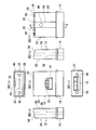
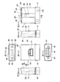
- 2 (a) to 2 (f) are six views showing the configuration of the optical ferrule of the first embodiment.
- FIG. 2A is a front view.
- FIG. 2B is a plan view.
- FIG. 2C is a bottom view.
- FIG. 2D is a left side view.
- FIG. 2E is a right side view.
- FIG. 2F is a rear view.
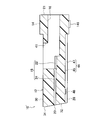
- FIG. 3 is a cross-sectional view in the AA direction of FIG.
- FIG. 7A to FIG. 7F are six views showing the configuration of the optical ferrule of the first embodiment.
- FIG. 7A is a front view.
- FIG. 7B is a plan view.
- FIG. 7C is a bottom view.
- FIG. 7D is a left side view.
- FIG. 7E is a right side view.
- FIG. 7F is a rear view. It is a perspective view which shows the structure of the optical ferrule shaping die of 1st Embodiment.
- FIGS. 12A and 12B are perspective views showing the configuration of the optical ferrule 10 ′ of the second embodiment.
- FIG. 12A is a perspective view seen from one side of the optical ferrule 10 ′.
- FIG. 12B is a perspective view seen from the other side of the optical ferrule 10 ′.
- FIGS. 13A to 13F are six views showing the configuration of the optical ferrule 10 ′ of the second embodiment.
- FIG. 13A is a front view.
- FIG. 13B is a plan view.
- FIG. 13C is a bottom view.
- FIG. 13D is a left side view.
- FIG. 13E is a right side view.
- FIG. 13F is a rear view.
- FIG. 14 is a cross-sectional view in the AA direction of FIG. It is sectional drawing in the AA direction of FIG.13 (f). It is sectional drawing to which the eject pin mark 146 of 2nd Embodiment was expanded. It is a perspective view which shows the structure of the optical ferrule shaping die 70 of 2nd Embodiment.
- An optical ferrule having an eject pin mark formed by an eject pin at the time of molding and holding an optical fiber comprising a ferrule main body, the ferrule main body including an optical fiber insertion port for inserting the optical fiber, and the light An optical fiber hole for exposing the end of the fiber; and a lower surface of the ferrule body serving as a reference surface.
- a recess is provided on the lower surface of the ferrule body, and the eject pin mark is located on the bottom surface of the recess.
- the optical ferrule is characterized in that the side surface of the recess is formed higher than the molding burr of the eject pin mark. According to such an optical ferrule, the molding burr can be prevented from protruding from the reference surface.
- the front end surface of the ferrule body provided with the optical fiber hole preferably has a front end inclined surface that is inclined so that the front edge of the lower surface is closer to the rear end surface of the ferrule body than the front edge of the upper surface. .
- it is particularly effective to provide a recess.
- the recess is formed with a width larger than the width of the tip portion of the eject pin, and the tip portion of the eject pin can be inserted. Thereby, an eject pin mark can be formed on the bottom surface of the recess.
- the eject pin mark is present in each of the recesses. Thereby, the bending deformation which arises in an optical ferrule can be suppressed.
- a flange portion is provided on the rear end side of the ferrule body and protrudes outward from the outer peripheral surface of the ferrule body, and the eject pin mark is present on the flange portion.
- the eject pin can be abutted against the optical ferrule so as to support the optical ferrule at three points.
- the ferrule body has an adhesive inlet that is provided on an upper surface of the ferrule body and injects an adhesive that fixes the optical fiber.
- the lower surface becomes the reference surface, it is particularly effective that the concave side surface is formed higher than the molding burr.
- An optical ferrule molding die for molding an optical ferrule having an eject pin mark formed by an eject pin at the time of molding and holding an optical fiber, the lower die having a cavity for molding a ferrule body, and the cavity
- An upper mold for covering, and a core disposed between the lower mold and the upper mold, and the ferrule body formed by the cavity includes an optical fiber insertion port for inserting the optical fiber;
- An optical fiber hole for exposing the tip of the optical fiber, and a lower surface of the ferrule body serving as a reference surface, and the lower mold has a lower surface molding surface for molding the lower surface of the ferrule body,
- the lower surface molding surface has a protrusion protruding into the cavity, and the protrusion has an eject pin hole through which the eject pin is inserted into the cavity.
- the light ferrule molding die characterized in that it is formed above the molding burrs of said ejector pin marks are clear. According to such an optical ferrule molding die, it is possible to prevent the molding burr from protruding from the reference surface of the optical ferrule.
- the lower mold has a front wall inclined surface for forming an inclined surface on a front end surface of the ferrule body, and the front wall inclined surface is inclined in a direction in which the side of the lower surface molding surface becomes narrower in the cavity. It is desirable that Thereby, a ferrule main body can be extruded from a metal mold
- An optical ferrule manufacturing method for holding an optical fiber having an eject pin mark formed by an eject pin at the time of molding, a lower mold having a cavity for molding a ferrule body, an upper mold for covering the cavity, A molding die assembling step for assembling a core disposed between the lower die and the upper die, a resin liquid injection step for injecting a resin solution into the cavity, and a resin solution injected into the cavity A resin curing step of curing the ferrule main body formed by the cavity, and a ferrule main body removing step of ejecting the ferrule main body by abutting an eject pin on the ferrule main body formed by the cavity.
- An optical fiber insertion port for inserting an optical fiber, and an optical fiber hole exposing the tip of the optical fiber A lower surface of the ferrule body serving as a reference surface, and the lower mold has a lower surface molding surface for molding the lower surface of the ferrule body, and the lower surface molding surface is a convex portion protruding into the cavity.
- the convex portion has an eject pin hole through which the eject pin is inserted into the cavity, and a side surface of the convex portion is formed higher than a molding burr of the eject pin mark, and the ferrule body is taken out.
- an optical ferrule manufacturing method is clarified, wherein the eject pin is abutted against the ferrule body from the eject pin hole of the convex portion. According to such an optical ferrule manufacturing method, it is possible to prevent the molding burr from protruding from the reference surface of the optical ferrule.
- a ferrule with an optical fiber having an optical ferrule and an optical fiber connected to the optical ferrule wherein the optical ferrule includes a ferrule body having an eject pin mark formed by an eject pin at the time of molding, and the ferrule body Has an optical fiber insertion port for inserting the optical fiber, an optical fiber hole for exposing the tip of the optical fiber, and a lower surface of the ferrule body serving as a reference surface, and a recess is formed in the lower surface of the ferrule body.
- the ferrule with an optical fiber is characterized in that the ejector pin mark is located on the bottom surface of the recess, and the side surface of the recess is formed higher than the molding burr of the eject pin mark. . According to such a ferrule with an optical fiber, the molding burr can be prevented from protruding from the reference surface of the optical ferrule. In addition, the following becomes clear.
- the optical ferrule is an optical ferrule that has an eject pin mark formed by being extruded with an eject pin at the time of molding and holds an optical fiber, and includes a resin ferrule main body formed in a substantially square shape, the ferrule main body An optical fiber insertion port for inserting the optical fiber, an optical fiber insertion path provided in the ferrule main body, communicating with the optical fiber insertion port, and inserting the optical fiber, and the ferrule main body.
- the front end surface of the ferrule main body includes a front end inclined surface that is inclined with respect to the optical fiber insertion path by bringing the front edge of the lower surface of the ferrule main body closer to the rear end surface of the ferrule main body than the front edge of the ferrule main body upper surface.
- a lower surface of the ferrule body as a reference surface, communicated with the optical fiber insertion path, and connected to the tip of the optical fiber.
- the concave side surface is formed higher than the molding burr of the eject pin mark.
- the optical ferrule includes a flange portion provided on the rear end side of the ferrule body and protruding outward from the outer peripheral surface of the ferrule body, and the recess is formed from the front end of the lower surface of the ferrule body. It is preferable that the groove is formed in a groove shape along the insertion direction of the optical fiber.
- the recess is preferably formed in a pair of concave grooves from the front edge of the lower surface of the ferrule body to the flange in a direction substantially parallel to the insertion direction of the optical fiber.
- the recess is provided on the lower surface of the ferrule main body and is formed in a hollow shape by surrounding the eject pin mark on the bottom surface of the recess with the side surface of the recess.
- the optical ferrule is provided on the rear end surface of the ferrule main body with the optical fiber insertion port interposed therebetween, and a pair of first guide ports into which guide pins are fitted, the ferrule main body is provided with the first guide port, A pair of guide pin insertion passages through which the guide pins are inserted, and the front end inclined surface of the ferrule body, with the optical fiber hole interposed therebetween, communicated with the guide pin insertion passages, It is preferable to include a pair of second guide ports to be fitted.
- the optical ferrule molding die is an optical ferrule molding die that molds an optical ferrule that holds an optical fiber and has an eject pin mark formed by being extruded by an eject pin at the time of molding, and is formed in a substantially square shape.
- a lower mold having a cavity for molding a resin ferrule body, an upper mold for covering the cavity, and a core disposed between the lower mold and the upper mold,
- the core is provided with a core body and an optical fiber insertion port that is provided to protrude from the core body, is disposed at the rear end of the cavity, and forms an optical fiber insertion port for inserting the optical fiber into a rear end surface of the ferrule body.
- An optical fiber insertion passage molding pin that is formed to project from the molding convex portion and the optical fiber insertion port molding convex portion and that forms an optical fiber insertion passage through which the optical fiber is inserted into the ferrule body.
- the upper mold body is formed to protrude from the cavity in the upper mold body and the upper mold body, and is disposed in contact with the optical fiber insertion port molding convex portion, and the ferrule body includes the An adhesive injection port forming convex portion for forming an adhesive injection port for injecting an adhesive for fixing the optical fiber
- the lower mold has a concave lower mold body forming the cavity
- the front wall surface on the cavity front end side of the lower mold body includes a front wall inclined surface inclined in a direction extending upward from the bottom wall surface on the cavity bottom side of the lower mold body, and the front wall inclined surface is
- the lower mold has an optical fiber hole forming portion for forming an optical fiber hole that is inserted with a tip end portion of an optical fiber insertion path forming pin and is positioned with
- the bottom wall of the body is the ferrule body A ferrule body bottom surface molding surface for molding a surface, the ferrule body bottom surface molding surface is provided to protrude from the cavity, and has a convex portion formed with a width larger than the width of the tip portion of the eject pin,
- the convex portion has an eject pin hole through which the eject pin is inserted into the cavity on the upper surface of the convex portion, and the convex side surface is formed higher than the molding burr of the eject pin mark.
- the bottom wall surface of the lower mold is a groove deeper than the bottom surface molding surface of the ferrule body from one side edge to the other side edge of the bottom wall surface at the rear end of the bottom surface molding surface of the ferrule body. And has a flange forming groove for forming a flange that protrudes from the outer peripheral surface of the ferrule body, and the convex portion extends from the front end of the ferrule body bottom surface forming surface to the flange forming groove. It is preferable that the optical fiber insertion path forming pin is formed in a convex shape along the longitudinal direction.
- the protrusions are formed in a pair of ridges from the front end of the ferrule body lower surface molding surface to the flange forming groove in a direction substantially parallel to the longitudinal direction of the optical fiber insertion path molding pin. Preferably it is formed.
- the convex part is preferably formed in an island shape on the molding surface of the lower surface of the ferrule body.
- the core is provided on the core body with the optical fiber insertion port molding convex portion interposed therebetween, and a pair of guide pin insertion passages for forming a guide pin insertion passage for inserting the guide pin.
- the lower mold is provided with the optical fiber hole forming portion sandwiched between the front wall inclined surface of the lower mold main body, and a distal end portion of the guide pin insertion passage forming pin is inserted, It is preferable to have a pair of guide port forming portions that form guide ports on the inclined front end surface of the ferrule body.
- An optical ferrule manufacturing method is an optical ferrule manufacturing method for holding an optical fiber having an eject pin mark formed by extrusion with an eject pin at the time of molding, and is a resin ferrule body formed in a substantially square shape
- a lower mold having a cavity for molding the upper mold, an upper mold for covering the cavity, and a core disposed between the lower mold and the upper mold.
- An optical fiber insertion port molding convex portion that is provided to project from the main body, is disposed at the rear end surface of the cavity, and forms an optical fiber insertion port for inserting the optical fiber into a rear end surface of the ferrule body;
- An optical fiber insertion passage forming pin that protrudes from the optical fiber insertion port forming convex portion and forms an optical fiber insertion passage through which the optical fiber is inserted into the ferrule body.
- the upper mold body and the upper mold body are formed so as to protrude into the cavity, and are placed in contact with the optical fiber insertion port molding convex portion, and an adhesive for fixing the optical fiber is injected into the ferrule body.
- An adhesive injection port forming convex portion for forming an adhesive injection port, and the lower mold has a concave lower mold body forming the cavity, and a cavity front end of the lower mold body
- the front wall surface on the side includes a front wall inclined surface inclined in a direction extending upward from the bottom wall surface on the cavity bottom side of the lower mold, and the front wall inclined surface has a tip portion of the optical fiber insertion path forming pin.
- An optical fiber hole forming portion that forms an optical fiber hole that is inserted and positioned with a lower surface of the ferrule body formed on the bottom wall surface of the lower mold as a reference surface, and the bottom wall surface of the lower mold body is A flange for forming the lower surface of the ferrule body.
- the ferrule main body lower surface molding surface is provided protruding from the cavity, and has a convexity formed with a width larger than the width of the tip portion of the eject pin, Molding die for assembling and clamping an optical ferrule molding die having an ejector pin hole through which the ejector pin is inserted into the cavity on the upper surface of the convexity, and the convex side surface formed higher than the molding burr of the ejector pin mark
- An assembly process a synthetic resin liquid injection process for injecting a synthetic resin liquid into the cavity of the optical ferrule molding mold; a resin curing process for resin curing the synthetic resin liquid injected into the cavity; and the optical ferrule molding metal Open the mold, push the eject pin against the ferrule body from the eject pin hole, and push out and remove the ferrule body And a ferrule body taking-out step.
- the optical connector is an optical connector in which an optical fiber is connected to an optical ferrule having an eject pin mark formed by being extruded by an eject pin at the time of molding, and the optical ferrule is a resin ferrule body formed in a substantially square shape An optical fiber insertion port provided in a rear end surface of the ferrule body for inserting the optical fiber; and an optical fiber insertion port provided in the ferrule body, communicating with the optical fiber insertion port and passing through the optical fiber.
- the front end surface of the passage and the ferrule body has a front end inclined surface that is inclined with respect to the optical fiber insertion passage by bringing the front edge of the lower surface of the ferrule body closer to the rear end surface of the ferrule body than the front edge of the upper surface of the ferrule body.
- Provided on the inclined surface of the front end positioned with the lower surface of the ferrule body as a reference surface, and inserted through the optical fiber.
- the bottom surface has the eject pin mark, and the side surface of the recess is formed higher than a molding burr of the eject pin mark, and the optical fiber is inserted from the optical fiber insertion port, inserted into the optical fiber insertion passage, The tip of the fiber from which the coating is removed from the optical fiber hole is exposed and connected to the optical ferrule.
- FIG. 1A and FIG. 1B are perspective views showing the configuration of the optical ferrule 10 of the first embodiment.
- FIG. 1A is a perspective view seen from one side of the optical ferrule 10.
- FIG. 1B is a perspective view seen from the other side of the optical ferrule 10.
- 2 (a) to 2 (f) are six views showing the configuration of the optical ferrule 10 of the first embodiment.
- FIG. 2A is a front view.
- FIG. 2B is a plan view.
- FIG. 2C is a bottom view.
- FIG. 2D is a left side view.
- FIG. 2E is a right side view.
- FIG. 2F is a rear view.
- FIG. 3 is a cross-sectional view in the AA direction of FIG.
- the optical ferrule 10 has a ferrule main body 12 and a flange 14 and has a function of holding a fiber.
- the ferrule body 12 is formed in a wide and substantially square shape.
- the flange 14 is provided on the rear end side of the ferrule body 12 and is formed to protrude outward from the outer peripheral surface of the ferrule body 12.
- the optical ferrule 10 holds, for example, an optical fiber such as a multi-core optical fiber tape in which a plurality of optical fibers of 2 to 12 fibers are taped.
- the optical fiber held by the optical ferrule 10 may be an optical fiber single-core wire or the like, as long as it has at least one optical fiber core wire.
- the optical ferrule 10 that holds a plurality of optical fiber core wires will be described.
- the ferrule body 12 is formed of a synthetic resin having a wide and substantially square shape.
- the ferrule body 12 is molded by, for example, transfer molding using a thermosetting resin such as an epoxy resin, injection molding using a thermoplastic resin such as polyphenylene sulfide resin (PPS) or liquid crystal polymer (LCP), or the like.
- a thermosetting resin such as an epoxy resin
- a thermoplastic resin such as polyphenylene sulfide resin (PPS) or liquid crystal polymer (LCP)
- the optical ferrule 10 has an optical fiber insertion port 16, an optical fiber insertion path 18, and an optical fiber hole 20.
- the optical fiber insertion port 16 is provided in the ferrule body 12 and is an insertion port for inserting a plurality of optical fiber core wires.
- the optical fiber insertion path 18 is a path for inserting a plurality of optical fiber core wires.
- the optical fiber hole 20 is a hole (opening) that exposes the ends of a plurality of optical fiber core wires.
- the optical fiber insertion port 16 is provided on the rear end surface 21 of the ferrule body 12 and has a function of inserting a plurality of optical fiber core wires into the ferrule body 12.
- the optical fiber insertion port 16 is formed, for example, in the approximate center of the rear end surface 21 of the ferrule body 12, and is formed in a wide, substantially rectangular shape that is large enough to insert an optical fiber tape.
- the optical fiber insertion path 18 is provided in the ferrule body 12, communicates with the optical fiber insertion port 16, and has a function of inserting a plurality of optical fiber core wires.
- the optical fiber insertion path 18 has an optical fiber guide groove 22 and a bare fiber insertion portion 24.
- the optical fiber guide groove 22 is a groove for guiding each optical fiber core wire.
- the bare fiber insertion portion 24 is a passage through which a bare fiber having a coating removed from the optical fiber core wire is inserted.
- the front end surface 26 of the ferrule body 12 includes a front end inclined surface 34.
- the front end inclined surface 34 is inclined with respect to the optical fiber insertion path 18 so that the front edge of the ferrule body lower surface 28 is closer to the rear end surface 21 of the ferrule body 12 than the front edge of the ferrule body upper surface 30.
- the plurality of optical fiber holes 20 are provided in the front end inclined surface 34 of the ferrule body 12, communicate with the optical fiber insertion path 18, and have a function of exposing the end of the bare fiber from which the coating is removed from the optical fiber core wire. Yes.
- the front end face 26 of the ferrule body 12 as an inclined connection end face including the front end inclined face 34, reflection can be suppressed when a plurality of optical fiber cores are abutted to make a connector connection or the like.
- the front end inclined surface 34 is formed with an inclination angle of approximately 8 degrees, for example.
- the plurality of optical fiber holes 20 are formed in parallel with the front end inclined surface 34 of the ferrule body 12.
- the plurality of optical fiber holes 20 may be arranged not only in parallel in one row but also in parallel in multiple rows such as two rows.
- the hole positions of the plurality of optical fiber holes 20 are positioned with the ferrule body lower surface 28 as a reference surface.
- the optical ferrule 10 has a pair of first guide ports 36, a pair of guide pin insertion passages 38, and a pair of second guide ports 40.
- the 1st guide port 36 is provided in the rear-end surface 21 of the ferrule main body 12, and a guide pin fits.
- the guide pin insertion passage 38 communicates with the first guide port 36 and is a passage for inserting the guide pin.
- the second guide port 40 is provided in the front end inclined surface 34 of the ferrule body 12, communicates with the guide pin insertion passage 38, and the guide pin is fitted therein.
- the pair of first guide ports 36 are provided with the optical fiber insertion port 16 in between.
- the center of the first guide port 36 is preferably positioned substantially in the same straight line as the center of each optical fiber core wire inserted into the optical fiber insertion port 16.
- the first guide port 36 has a substantially circular cross-sectional shape in a direction substantially orthogonal to the insertion direction of the guide pin.
- the pair of guide pin insertion passages 38 are provided in the ferrule main body 12 with the optical fiber insertion passage 18 interposed therebetween, communicate with the first guide port 36, and have a function of inserting the guide pins.
- the pair of guide pin insertion passages 38 is provided in a direction substantially parallel to the insertion direction of the plurality of optical fiber core wires.
- the pair of second guide ports 40 are provided on both sides of the front end inclined surface 34 of the ferrule body 12 with an optical fiber hole array composed of a plurality of optical fiber holes 20 interposed therebetween, and are formed in communication with the guide pin insertion passage 38. .
- the center of the second guide port 40 is preferably positioned substantially in the same straight line as the centers of the plurality of optical fiber holes 20.
- the second guide port 40 has a substantially circular cross-sectional shape in a direction substantially orthogonal to the insertion direction of the guide pin.
- the adhesive injection port 41 is provided on the upper surface 30 of the ferrule body, communicates with the optical fiber insertion path 18, and has a function of injecting and filling an adhesive for fixing a plurality of optical fiber core wires into the optical fiber insertion path 18. is doing.
- the adhesive injection port 41 is formed in a substantially rectangular or polygonal hollow shape.
- the adhesive inlet 41 is preferably provided on the rear end side of the upper surface 30 of the ferrule body. ⁇ Positional relationship between reference plane and eject pin mark>
- the upper surface of the ferrule is defined as a surface forming an adhesive filling window for filling an adhesive for fixing the optical fiber
- the lower surface of the ferrule is defined as a reference surface.
- an optical ferrule with an inclined connection end surface that is inclined with the front edge of the lower surface of the ferrule inclined closer to the rear end surface of the optical ferrule than the front edge of the upper surface of the ferrule has an optical fiber on the upper surface of the ferrule protruding forward
- An adhesive filling window for filling the adhesive for fixing the ferrule is formed, and the lower surface of the ferrule has a function as a reference surface of the optical ferrule.
- the inclined connection end face is obtained by polishing the vertical connection end face.
- a ferrule having an inclined end face in which the connection end face is formed obliquely in advance has been developed.
- a resin-made optical ferrule formed of a synthetic resin is formed by molding (described later).
- the molding die for molding the optical ferrule is preferably composed of an upper die, a lower die, and a core. This is because when the optical ferrule is released from the molding die, the mold opening of the molding die is further simplified.
- the lower surface of the ferrule is the mold surface of the lower mold Oppositely, the upper surface of the ferrule is configured to face the mold surface of the upper mold (described later).
- the inclined mold surface forming the inclined connection end surface is preferably provided integrally with the lower mold.
- the inclined mold surface that forms the inclined connection end surface is provided integrally with the lower mold.
- the inclined mold surface that is inclined so as to spread from the lower surface of the cavity toward the upper surface of the cavity does not interfere with the optical ferrule from the lower mold side. It can be ejected with an eject pin. Therefore, in an optical ferrule having an inclined connection end surface in which the front edge of the lower surface of the ferrule is inclined closer to the rear end surface of the optical ferrule than the front edge of the upper surface of the ferrule, an eject pin mark is formed on the lower surface of the ferrule body serving as a reference surface. .
- a molding burr by the head of the eject pin is formed on the eject pin mark formed at the time of molding. If the eject pin mark is formed on the reference surface of the optical ferrule, the molding burr protrudes from the reference surface, so that the surface smoothness is impaired and the function as the reference surface may be lowered. Therefore, as will be described below, a recess is provided on the lower surface of the ferrule body serving as the reference surface so that the molding burr does not protrude from the reference surface.
- the recess 44 is provided in the lower surface 28 of the ferrule main body, is formed with a width larger than the tip of the eject pin, and is formed so that the tip of the eject pin can be inserted.
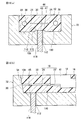
- the recess 44 has an eject pin mark 46 on the bottom surface 45 of the recess.
- the concave side surface 47 is formed higher than the molding burr of the eject pin mark 46.
- the recess 44 is preferably formed in a concave groove shape from the front end of the ferrule main body lower surface 28 to the flange 14 along the insertion direction of the optical fiber core wire.
- the groove width of the recess 44 is formed larger than the tip end portion of the eject pin.
- the groove cross section in a direction substantially orthogonal to the optical fiber insertion direction is preferably formed in, for example, a U-shape in which the angle between the groove bottom surface and the groove side surface is substantially a right angle.
- the groove cross section is not limited to the U-shape, and one groove side surface and the other groove side surface may be tapered.
- the die ferrule body 12 is molded by abutting the tip of the eject pin against the recess bottom surface 45 when releasing the molding die. Can be released from the molding die.
- the eject pin mark 46 is formed in the recess bottom surface 45 in a concavo-convex shape with a burr formed by abutting the tip of the eject pin against the recess bottom surface 45.
- the eject pin mark 46 is formed on the front end face 26 side of the recess bottom face 45, for example.
- the eject pin mark 46 may be formed substantially at the center of the bottom surface 45 of the recess, or may be formed on the flange 14 side of the bottom surface 45 of the recess.
- the tip cross section of the eject pin is substantially circular, the eject pin mark 46 is formed in a substantially circular shape.
- the tip cross section of the eject pin is substantially rectangular, the eject pin mark 46 is formed in a substantially rectangular shape (also common to other embodiments).
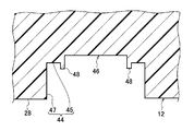
- FIG. 4 is an enlarged cross-sectional view of the recess 44.
- the recess 44 is formed such that the recess side surface 47 is higher than the molding burr 48 of the eject pin mark 46. Since the concave side surface 47 is formed higher than the projection of the molding burr 48 formed on the concave and convex eject pin mark 46, the projection of the molding burr 48 can be suppressed from protruding from the ferrule body lower surface 28 which is the reference surface. .
- the height of the molding burr 48 formed on the eject pin mark 46 can be obtained by, for example, experiments.
- the concave side surface 47 is formed higher than the maximum protrusion of the molding burr 48 formed on the concave and convex eject pin mark 46.
- the recess 44 is provided at the approximate center in the direction substantially orthogonal to the optical fiber insertion direction on the ferrule main body lower surface 28, but is not limited to the approximate center.
- the recess 44 may be provided on one side of the ferrule body 12 or may be provided on the other side of the ferrule body 12.
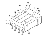
- FIG. 5 is a perspective view showing the configuration of another optical ferrule 50.
- the recess 44 is preferably provided in a pair of concave grooves from the front edge of the ferrule main body lower surface 28 to the flange 14 in a direction substantially parallel to the insertion direction of the optical fiber core wire.
- the pair of recesses 44 is formed in a groove shape with a predetermined interval in a direction substantially parallel to the insertion direction of the optical fiber core wire.
- Eject pin marks 46 are respectively formed in the pair of recesses 44.
- the optical ferrule 50 it is possible to suppress the protrusion of the molding burr 48 of the eject pin mark 46 from the lower surface 28 of the ferrule body that is the reference surface. Furthermore, according to the optical ferrule 50, the molded ferrule body 12 can be abutted with two eject pins and released from the molding die, so that one recess 44 is provided and molded with one eject pin. It is possible to remove the ferrule body 12 from the molding die while suppressing the bending deformation of the ferrule body 12 as compared with the case where the subsequent ferrule body 12 is removed.
- FIG. 6 is a perspective view showing the configuration of another optical ferrule 60.
- FIG. 7A to FIG. 7F are six views showing the configuration of the optical ferrule 60.
- FIG. 7A is a front view.
- FIG. 7B is a plan view.
- FIG. 7C is a bottom view.
- FIG. 7D is a left side view.
- FIG. 7E is a right side view.
- FIG. 7F is a rear view.
- the recess 62 is preferably provided in the lower surface 28 of the ferrule body which is a reference surface, and is formed in a recess shape by surrounding the eject pin pin 46 on the recess bottom surface 63 with the recess side surface 64.
- the recess 62 is formed in a substantially rectangular shape, for example.
- the recess 62 is larger than the width of the tip portion of the eject pin, and is formed so that the tip portion of the eject pin can be inserted.
- the recess 62 has an uneven eject pin mark 46 formed by abutting the tip of the eject pin against the recess bottom surface 63.
- the concave side surface 64 surrounding the eject pin mark 46 is formed higher than the molding burr 48 of the eject pin mark 46.
- the shape of the recess 62 is not limited to a substantially rectangular shape, and may be a substantially circular shape or the like.
- the recess 62 may not have a completely closed outline in plan view and may be partially missing. That is, a part of the recess 62 may extend on the ferrule side surface.
- the recess 62 may be formed on the front end surface side of the ferrule main body lower surface 28, or approximately at the center of the ferrule main body lower surface 28, one side edge side or the other side edge side of the ferrule main body lower surface 28, the ferrule main body lower surface 28. It may be formed on the side of the collar 14. Further, it is sufficient that at least one recess 62 is formed. According to the optical ferrule 60, the protrusion of the molding burr 48 of the eject pin mark 46 from the ferrule main body lower surface 28, which is the reference surface, can be suppressed, and the reference surface can be provided wider.
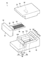
- FIG. 8 is a perspective view showing the configuration of the optical ferrule molding die 70 of the first embodiment.
- the optical ferrule molding die 70 includes a lower die 72, an upper die 74, and a core 76.
- the lower mold 72 has a cavity for molding the ferrule body 12.
- the upper mold 74 is a mold for covering the cavity.
- the core 76 is disposed between the lower mold 72 and the upper mold 74.
- the lower mold 72, the upper mold 74, and the core 76 are made of, for example, a metal material or an inorganic material.
- the upper mold 74 has an upper mold body 78 and an adhesive injection port molding convex portion 80.
- the adhesive injection port forming convex portion 80 is provided in the upper mold main body 78 so as to protrude toward the cavity, and an adhesive injection port 41 for injecting an adhesive for fixing a plurality of optical fiber core wires to the ferrule main body 12. Is molded.
- the upper mold 74 has a resin injection port (not shown). This resin injection port is provided in the upper mold body 78 in communication with the cavity, and is an injection port for injecting a synthetic resin liquid for molding the ferrule body 12 into the cavity.
- the core 76 has a core body 84, an optical fiber insertion port molding convex part 86, and a plurality of optical fiber insertion path molding pins 88.
- the optical fiber insertion port forming convex portion 86 is provided so as to protrude from the front end surface of the core body 84, and forms the optical fiber insertion port 16 into which a plurality of optical fiber core wires are inserted.
- the optical fiber insertion passage forming pin 88 is provided so as to protrude from the optical fiber insertion port forming convex portion 86 and forms the optical fiber insertion passage 18 through which a plurality of optical fiber core wires are inserted.
- the optical fiber insertion port forming convex portion 86 is provided so as to protrude from the front end surface of the core body 84, has a substantially square shape, and has a function of forming the substantially rectangular optical fiber insertion port 16. ing.
- the plurality of optical fiber insertion path forming pins 88 protrude from the optical fiber insertion port forming convex portion 86 and are formed in an elongated shape.
- the plurality of optical fiber insertion path forming pins 88 are arranged, for example, in parallel in one row.
- the plurality of optical fiber insertion path forming pins 88 may be arranged in a plurality of rows such as two rows.
- the core 76 has a pair of guide pin insertion passage forming pins 90.
- the guide pin insertion passage forming pins 90 are provided on both sides of the core body 84 with the optical fiber insertion port forming convex portion 86 interposed therebetween, and form the guide pin insertion passage 38 through which the guide pin is inserted.
- the pair of guide pin insertion passage forming pins 90 are arranged on both sides of the optical fiber insertion port forming convex portion 86 and the plurality of optical fiber insertion passage forming pins 88.
- the pair of guide pin insertion passage forming pins 90 is formed in an elongated shape in a direction substantially parallel to the longitudinal direction of the optical fiber insertion passage forming pins 88.
- the optical fiber insertion port forming convex portion 86, the plurality of optical fiber insertion passage forming pins 88, and the pair of guide pin insertion passage forming pins 90 are positioned in the cavity when the mold is clamped.
- the lower mold 72 has a concave lower mold body 75 provided with a cavity for molding the ferrule body 12.
- the lower mold body 75 includes a bottom wall surface 92, a first side wall surface 94, a second side wall surface 96, and a front wall surface 98.
- the first side wall surface 94 is provided on one side edge of the bottom wall surface 92.
- the second side wall surface 96 is provided on the other side edge of the bottom wall surface 92 so as to face the first side wall surface 94.
- the front wall surface 98 is in contact with the front end of the first side wall surface 94 and the front end of the second side wall surface 96.
- the rear end side facing the front wall surface 98 has an open structure.
- the cavity is formed by being surrounded by the first side wall surface 94, the second side wall surface 96, and the front wall surface 98.
- the bottom wall surface 92 of the lower mold body 75 has a ferrule body lower surface molding surface 100 for molding the ferrule body lower surface 28.
- the bottom wall surface 92 of the lower mold body 75 has a flange forming groove 102 at the rear end of the ferrule body lower surface molding surface 100.
- the flange forming groove 102 is formed in a groove shape deeper than the ferrule body lower surface molding surface 100 from the first side wall surface 94 side to the second side wall surface 96 side, and forms the flange portion 14 provided at the rear end of the ferrule body 12. To do.
- a front wall surface 98 on the cavity front end side of the lower mold body 75 includes a front wall inclined surface 104.
- the front wall inclined surface 104 is an inclined surface inclined in a direction extending upward from the bottom wall surface 92 on the cavity bottom side of the lower mold body 75. (That is, the front wall inclined surface 104 is inclined so that the side of the bottom wall surface 92 with the eject pin 118 is narrowed in the cavity.
- This front wall inclined surface 104 has the front end inclined surface 34 (the front edge of the ferrule main body lower surface 28 is made closer to the rear end surface 21 of the ferrule main body 12 than the front edge of the ferrule main body upper surface 30).
- the front end face 26 of the ferrule body 12 having a front end inclined face 34) inclined with respect to the optical fiber insertion path 18 is formed.
- the front wall inclined surface 104 is inclined so as to protrude from the bottom wall surface 92 on the cavity bottom side to the front side of the lower mold body 75 toward the upper side of the cavity on the upper mold 74 side. That is, the front wall inclined surface 104 is provided so as to be inclined in a direction extending upward from the bottom wall surface 92 of the lower mold body 75.
- the front wall inclined surface 104 has an optical fiber hole forming portion into which the tip of the optical fiber insertion passage forming pin 88 is inserted.
- the optical fiber hole forming portion has a plurality of optical fiber hole forming holes 106.
- the optical fiber hole forming hole 106 is precisely machined so as to have a predetermined positional relationship with the bottom wall surface 92.
- the optical fiber insertion hole forming pin 88 uses the ferrule body lower surface 28 formed by the ferrule body lower surface molding surface 100 of the bottom wall surface 92 as a reference surface, and the optical fiber hole 20 is positioned at a predetermined position with respect to this reference surface.
- the bare fiber insertion portion 24 is formed.
- the inner diameter of the optical fiber hole forming hole 106 is substantially the same as the outer diameter of the optical fiber insertion hole forming pin 88, and the tip of the optical fiber insertion hole forming pin 88 is inserted into the optical fiber hole forming hole 106. The gap between them is very narrow.
- the synthetic resin does not have a gap around the optical fiber hole forming hole 106.
- the amount of penetration is negligible.
- the synthetic resin that has entered the gap around the optical fiber hole forming hole 106 becomes a molding burr generated on the inclined surface 34 of the front end of the ferrule body 12, but since this molding burr is small, it is removed by simple polishing after molding. The industrial productivity is not greatly reduced.
- the optical fiber hole forming portion is preferably composed of a plurality of optical fiber hole forming holes 106 in order to increase the degree of freedom of the hole position of the optical fiber hole 20 when the optical ferrule 10 is designed.
- the plurality of optical fiber hole forming holes 106 are provided in parallel to the front wall inclined surface 104.
- the optical fiber hole forming holes 106 may be provided in one row, or may be provided in a plurality of rows such as two rows.
- the optical fiber insertion passage molding pins 88 are in a plurality of rows, and the tip portion of the optical fiber insertion passage molding pins 88 is inserted.
- the optical fiber hole forming holes 106 are arranged in a plurality of rows, the rows of optical fiber insertion passage forming pins 88 are parallel to each other, and the rows of optical fiber hole forming holes 106 are also parallel to each other.
- the optical fiber hole forming portion is not limited to the optical fiber hole forming hole 106, and may be constituted by, for example, a V-groove-shaped optical fiber hole forming groove formed in the front wall inclined surface 104.
- a plurality of optical fiber holes 20 can be formed by inserting and fixing the distal end portion of the optical fiber insertion path forming pin 88 into the optical fiber hole forming groove. That is, the means for positioning the distal end portion of the optical fiber insertion path molding pin 88 is not limited to positioning by a round hole (or a substantially round hole such as an ellipse) as in the present embodiment.
- the tip of the optical fiber insertion path molding pin 88 can be positioned by a V groove or the like. In this case, the tip end portion of the optical fiber insertion passage molding pin 88 is positioned using the V-groove formed at the same pitch as the arrangement pitch of the optical fiber insertion passage molding pins 88.
- the lower mold body 75 preferably has a pair of guide port forming portions that form a pair of second guide ports 40 on the front end inclined surface 34 of the ferrule body 12 on the front wall inclined surface 104.
- the pair of guide port forming portions are provided with a plurality of optical fiber hole forming holes 106 interposed therebetween, and the tip portions of the guide pin insertion passage forming pins 90 are inserted.
- the pair of guide port forming portions is configured by a pair of guide port forming holes 108 when the optical fiber hole forming portion is configured by the optical fiber hole forming holes 106.
- the guide port forming holes 108 are formed on both sides of an optical fiber hole forming hole array composed of a plurality of optical fiber hole forming holes 106.
- a second guide port 40 is formed on the front end inclined surface 34.
- molding part is comprised by a pair of V groove-shaped guide port shaping
- the pair of second guide ports 40 can be formed by inserting and fixing the distal end portion of the guide pin insertion passage forming pin 90 into the guide port forming groove.
- the ferrule body lower surface molding surface 100 for molding the ferrule body lower surface 28 has a convex portion 109.
- the convex portion 109 protrudes from the cavity and is formed with a width larger than the width of the tip portion of the eject pin.
- the convex portion 109 has an eject pin hole through which the eject pin 118 is inserted into the cavity on the convex top surface 110.
- the convex side surface 113 is formed higher than the molding burr 48 of the eject pin mark 46.
- the convex portion 109 is preferably formed in a convex shape along the longitudinal direction of the optical fiber insertion passage forming pin 88 from the front end of the ferrule body lower surface forming surface 100 to the flange forming groove 102.
- the convex portion 109 is provided on the ferrule main body lower surface molding surface 100 so as to protrude into the cavity, whereby the concave portion 44 is formed on the lower surface 28 of the ferrule main body. Further, since the convex portion 109 is formed with a width larger than the width of the distal end portion of the eject pin 118, the groove width of the concave portion 44 formed in the ferrule main body lower surface 28 is larger than the width of the distal end portion of the eject pin 118. It is formed.
- the convex portion 109 has an eject pin hole through which the eject pin 118 is inserted into the cavity on the convex upper surface 110, the ferrule main body 12 is pushed down by the eject pin 118 so that the ferrule main body 12 is moved to the lower mold. 72.
- An eject pin mark 46 is formed on the bottom surface 45 of the recess on the lower surface 28 of the ferrule body.
- the eject pin hole is provided, for example, on the front wall surface 98 side of the convex portion 109 formed on the ridge.
- the eject pin hole may be provided in the flange forming groove 102 side, or may be provided in the approximate center between the front wall surface 98 and the flange forming groove 102.
- the eject pin hole has, for example, a substantially circular or substantially rectangular cross section in a direction substantially orthogonal to the insertion direction of the eject pin 118.
- the convex portion 109 is formed such that the convex side surface 113 is higher than the molding burr 48 of the eject pin mark 46.
- the concave side surface 47 of the ferrule main body lower surface 28 is formed higher than the molding burr 48 of the eject pin mark 46.
- the convex portion 109 is formed in a straight line from the front end of the ferrule main body lower surface forming surface 100 to the flange forming groove 102 in a convex shape, so that the concave portion 44 is formed into a concave groove shape from the front end of the ferrule main body lower surface 28 to the flange portion 14. Is formed.
- the convex portion 109 formed on the convex line is provided in a straight line from the front end of the ferrule main body lower surface molding surface 100 to the flange molding groove 102. Thereby, the surface formation process for forming the ferrule main body lower surface molding surface 100 and the formation of the convex portion 109 can be performed in one step.
- the productivity of the optical ferrule molding die 70 is further improved.
- the cutting tool is inserted into the cavity from the opening on the rear end side of the lower mold body 75, and the cutting tool is slid with respect to the bottom wall surface 92 of the lower mold body 75, whereby the surface of the ferrule body lower surface molding surface 100.
- the forming process and the formation of the convex portion 109 can be performed in one step.
- the flange forming groove 102 is formed at a position lower than the ferrule main body lower surface forming surface 100, so that it does not hinder cutting.
- the recess 44 when the recess 44 is provided in a pair of recess grooves (the recess 44 extends from the front edge of the lower surface 28 of the ferrule body in a direction substantially parallel to the insertion direction of the optical fiber core wire.
- the convex portion 109 provided on the ferrule body lower surface molding surface 100 has a pair of convexities in a direction substantially parallel to the longitudinal direction of the optical fiber insertion path molding pin 88. Provided.
- the convex portions 109 formed on the pair of ridges are provided substantially linearly on the ferrule main body lower surface molding surface 100 from the front edge of the ferrule main body lower surface molding surface 100 to the flange molding groove 102 in a substantially parallel manner with a predetermined interval. It is done.
- FIG. 9 is a perspective view showing a configuration of an optical ferrule molding die in which the recess 62 is formed in the ferrule body lower surface 28. Similar to the convex portion 109, the convex portion 115 formed in an island shape has an eject pin hole 112 through which the eject pin is inserted into the cavity on the convex upper surface 116, and the convex side surface 117 is a molding burr of the eject pin mark 46. It is formed higher than 48. Thereby, the recess 62 is formed in a recess shape by surrounding the eject pin mark 46 on the recess bottom surface 63 with the recess side surface 64.
- the manufacturing method of the optical ferrule 10 includes a molding die assembling step, a synthetic resin liquid injection step, a resin curing step, and a ferrule body taking-out step.
- the molding die assembling step is a step of assembling and clamping the optical ferrule molding die 70.
- the synthetic resin liquid injection process is a process of injecting a synthetic resin liquid into the cavity of the optical ferrule molding die 70.
- the resin curing step is a step of curing the synthetic resin liquid injected into the cavity.
- the ferrule body taking-out step is to take out the ferrule body 12 by opening the optical ferrule molding die 70.
- the molding die assembling step is a step of clamping the optical ferrule molding die 70 by positioning and assembling the core 76 between the upper die 74 and the lower die 72.
- the core 76 is disposed such that the front end surface of the core main body 84 is in contact with the rear end of the first side wall surface 94 and the rear end of the second side wall surface 96 of the lower mold main body 75.
- the optical fiber insertion port molding convex part 86, the optical fiber insertion path molding pin 88, and the guide pin insertion path molding pin 90 include a first side wall surface 94, a second side wall surface 96, a front wall surface 98, and a core body 84. It arrange
- the distal end portion of the optical fiber insertion path forming pin 88 is inserted into the optical fiber hole forming hole 106 provided in the front wall inclined surface 104 of the lower mold body 75.
- the distal end portion of the guide pin insertion passage forming pin 90 is inserted into a guide port forming hole 108 provided in the front wall inclined surface 104 of the lower mold body 75.
- the adhesive injection port molding convex portion 80 of the upper mold 74 is disposed in the cavity in contact with the optical fiber insertion port molding convex portion 86 of the core 76. In this manner, the upper die 74, the lower die 72, and the core 76 are assembled, and the clamping of the optical ferrule molding die 70 is completed.
- the synthetic resin liquid injection process is a process of injecting the synthetic resin liquid into the cavity of the optical ferrule molding die 70.
- a thermosetting resin liquid such as an epoxy resin, or a thermoplastic resin liquid such as a polyphenylene sulfide resin or a liquid crystal polymer is used.
- the synthetic resin liquid is injected into the cavity from the resin injection port of the upper mold 74.
- the molding die is preferably heated to a predetermined temperature before the synthetic resin liquid is injected into the cavity.
- the resin curing step is a step of curing the synthetic resin liquid injected into the cavity of the optical ferrule molding die 70.
- the synthetic resin liquid is a thermosetting resin liquid
- the synthetic resin liquid can be cured by heating the optical ferrule molding die 70 into which the synthetic resin liquid is injected to a predetermined curing temperature.
- the synthetic resin liquid is a thermoplastic resin liquid
- the synthetic resin liquid can be cured by cooling the optical ferrule molding die 70 into which the synthetic resin liquid has been injected to a predetermined temperature.
- the ferrule main body taking-out step is a step of taking out the ferrule main body 12 formed by opening the optical ferrule molding die 70 and curing the resin.
- FIG. 10A and FIG. 10B are cross-sectional views showing a process for removing the ferrule body 12.
- FIG. 10A is a cross-sectional view substantially perpendicular to the insertion direction of the optical fiber core wire.
- FIG.10 (b) is sectional drawing of a substantially parallel direction with respect to the insertion direction of an optical fiber core wire.
- the optical ferrule molding die 70 is opened, and the upper die 74 and the core 76 are removed from the ferrule body 12.
- the eject pin 118 is abutted against the concave bottom surface 45 of the ferrule body 12 from the eject pin hole 112 provided on the convex top surface 110 of the bottom wall surface 92 of the lower mold body 75, and the ferrule body 12 is pushed upward. put out.
- An eject pin mark 46 having a molding burr 48 is formed on the bottom surface 45 of the recess against which the eject pin 118 is abutted.
- the front wall inclined surface 104 of the lower mold main body 75 is inclined so as to widen outward from the bottom wall surface 92 on the cavity bottom side, the front wall inclined surface when the ferrule main body 12 is pushed upward. There is no hindrance at 104. Thus, the manufacture of the optical ferrule 10 is completed.
- the optical ferrule 10 having the front end inclined surface 34 that is inclined so that the front edge of the reference surface is closer to the rear end surface than the front edge of the upper surface (the surface having the adhesive inlet) (see FIG. 3).
- the eject pin 118 is abutted upward from the lower mold 72 having the front wall inclined surface 104 inclined so that the side of the bottom wall surface 92 with the eject pin 118 is narrowed in the cavity. Yes.
- the ferrule body 12 can be removed from the mold without separately disassembling the mold formed with the bottom wall surface 92 and the mold formed with the front wall inclined surface 104. Can be extruded.
- the convex portion 109 is provided on the bottom wall surface 92 of the lower mold 75, and the side surface of the convex portion 109 is made higher than the molding burr. Thereby, a recess is formed in the reference surface of the ferrule body 12 formed in the cavity, and the side surface of the recess becomes higher than the molding burr, so that the molding burr does not protrude from the reference surface.
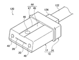
- an optical connector 120 (an optical ferrule with an optical fiber) is manufactured by connecting an optical fiber to the optical ferrule 10.
- FIG. 11 is a perspective view showing the configuration of the optical connector 120.
- an optical fiber tape 122 is used as the optical fiber.
- the optical fiber tape 122 includes a plurality of optical fiber core wires. When the plurality of optical fiber cores are connected to the optical ferrule 10, the tip portions of the plurality of optical fiber cores are removed from the coating.
- the optical fiber tape 122 is inserted from the optical fiber insertion port 16 of the optical ferrule 10.
- a rubber boot 124 for protecting the optical fiber core wire is attached to the optical fiber insertion port 16.
- the plurality of optical fiber core wires are guided by the optical fiber guide groove 22 and inserted through the optical fiber insertion path 18.
- the tip portions of the plurality of optical fiber core wires are attached so as to protrude from the optical fiber hole 20 by a predetermined amount. And by inject
- the optical ferrule provided with the inclined surface on the front end surface of the ferrule main body 12 has been described.
- the front end surface of the ferrule main body is substantially perpendicular to the upper surface of the ferrule main body and the lower surface of the ferrule main body.
- a recess having an eject pin mark may be provided on a reference surface such as an optical ferrule having a connection end surface formed vertically.
- Such an optical ferrule includes a ferrule body formed in a substantially square shape with a synthetic resin, and is provided on the rear end surface of the ferrule body.
- a reference surface that serves as a reference for positioning the optical fiber hole on the outer peripheral surface of the ferrule body, is formed on the reference surface and is wider than the width of the tip of the eject pin, and the tip of the eject pin is inserted It has a possible recess, and the recess has an eject pin mark on the bottom surface of the recess, and the side surface of the recess is formed higher than a molding burr of the eject pin mark.
- An optical ferrule molding mold for molding such an optical ferrule includes a lower mold having a cavity for molding a ferrule body formed in a substantially square shape with a synthetic resin, an upper mold for covering the cavity, and a lower mold. And a core disposed between the upper die and the upper mold, the core projecting from the core body and disposed at the rear end of the cavity, and the rear end surface of the ferrule body An optical fiber insertion port forming convex portion for forming an optical fiber insertion port for inserting a fiber, and an optical fiber formed to project from the optical fiber insertion port forming convex portion and forming an optical fiber insertion passage through which the optical fiber is inserted into the ferrule body
- the lower mold has a concave lower mold body that forms a cavity, and the front wall surface on the cavity front end side of the lower mold body is the tip of the optical fiber insertion mold Inserted
- the front end surface of the ferrule body has an optical fiber hole forming hole for forming an optical fiber hole, and the
- the reference surface molding surface is provided to protrude into the cavity, and has a convex portion formed with a width larger than the width of the tip portion of the eject pin.
- the convex portion is formed on the upper surface of the convex pin.
- a convex side surface is formed higher than the molding burr of the eject pin mark.
- the reference surface that serves as a reference for positioning the optical fiber hole and is formed with a width larger than the width of the tip of the eject pin, so that the tip of the eject pin can be inserted Since the recess has an eject pin mark on the bottom surface of the recess and the side surface of the recess is formed higher than the molding burr of the eject pin mark, the protrusion of the molding burr can be suppressed from the reference surface. it can.
- the reference surface serving as a reference for positioning the optical fiber hole is not limited to the lower surface of the ferrule body, and can be provided on the outer peripheral surface of the ferrule body such as the upper surface of the ferrule body.
- a reference surface molding surface provided in an optical ferrule molding die for molding an optical ferrule having a connection end surface formed vertically is formed on the cavity side wall surface of the upper die or the lower die.
- the optical ferrule having the above-described configuration is an inclined connection end face inclined with respect to the optical fiber insertion path (specifically, the front edge of the lower surface of the ferrule body serving as a reference for positioning the optical fiber hole is moved from the front edge of the upper surface of the ferrule body And an inclined connection end face which is inclined with respect to the optical fiber insertion path close to the rear end face of the main body.
- the upper surface of the ferrule body has an adhesive injection port (an adhesive injection port for injecting an adhesive that communicates with the optical fiber insertion path and fixes the optical fiber).
- the lower surface of the ferrule body has a recess (a recess formed with a width larger than the width of the tip of the eject pin and into which the tip of the eject pin can be inserted).
- This recess has an eject pin mark on the bottom surface of the recess.
- the bottom wall surface of the lower mold main body includes a ferrule main body lower surface molding surface (a ferrule main body lower surface molding surface for molding a ferrule main body lower surface serving as a reference for positioning an optical fiber hole).
- the ferrule main body lower surface molding surface has a convexity (a convexity provided to protrude into the cavity and formed with a width larger than the width of the tip portion of the eject pin).
- the convex portion has an eject pin hole through which the eject pin is inserted into the cavity.
- the optical ferrule molding die having the above configuration, since the convex side surface is formed higher than the molding burr of the eject pin mark, the optical ferrule having the concave portion on the lower surface of the ferrule body can be molded. .
- the optical ferrule can be molded without impairing the function as the reference surface of the ferrule main body lower surface, so that the oblique end surface molding of the connection end surface can be performed by die molding. .
- the positional accuracy of the optical fiber hole is further improved, and the oblique end face polishing after the molding of the mold is not required, so that the number of polishing steps is reduced.
- the bottom wall surface of the lower mold is formed at the rear end of the lower surface molding surface of the ferrule body, with a flange forming groove (from one side edge to the other side edge of the bottom wall surface). It is formed in a groove shape deeper than the lower surface molding surface, and has a flange forming groove for forming a flange portion protruding from the outer peripheral surface of the ferrule body.
- the convexity is formed on the ridge along the longitudinal direction of the optical fiber insertion passage molding pin from the front end of the ferrule body lower surface molding surface to the flange molding groove, the surface forming process for forming the ferrule body lower surface molding surface And the formation of the convex portion can be performed in one step. Thereby, the productivity of the optical ferrule molding die is further improved.
- the convex portion is a pair of convex stripes from the front end of the ferrule body lower surface molding surface to the flange molding groove in a direction substantially parallel to the longitudinal direction of the optical fiber insertion path molding pin. Formed.
- the ferrule body can be abutted with the two eject pins and released from the molding die. Therefore, it is possible to remove the ferrule body from the molding die while suppressing the bending deformation of the ferrule body, compared to the case where one recess is provided on the lower surface of the ferrule body and the ferrule body is taken out by one eject pin.
- the manufacturing method of the optical ferrule having the above configuration includes a molding die assembling step (step of clamping the optical ferrule molding die) and a synthetic resin liquid injection step (injecting a synthetic resin liquid into the cavity of the optical ferrule molding die). Step), a resin curing step (step of curing the synthetic resin liquid injected into the cavity), and a ferrule body removal step (an ejector provided on the convex surface of the bottom surface of the ferrule body on the bottom wall of the lower mold) And a step of taking out the optical ferrule by abutting the eject pin from the pin hole against the ferrule body.
- the optical connector having the above-described configuration, by holding a plurality of optical fiber core wires using the optical ferrule, the protrusion of the molding burr included in the eject pin mark from the lower surface of the ferrule body serving as a reference for positioning the optical fiber hole Can be suppressed.
- the eject pin is abutted not only on the lower surface of the ferrule body serving as the reference surface, but also on the lower surface of the collar portion.
- FIG. 12A and FIG. 12B are perspective views showing the configuration of the optical ferrule 10 ′ of the second embodiment.
- FIG. 12A is a perspective view seen from one side of the optical ferrule 10 ′.
- FIG. 12B is a perspective view seen from the other side of the optical ferrule 10 ′.
- FIGS. 13A to 13F are six views showing the configuration of the optical ferrule 10 ′ of the second embodiment.
- FIG. 13A is a front view.
- FIG. 13B is a plan view.
- FIG. 13C is a bottom view.
- FIG. 13D is a left side view.
- FIG. 13E is a right side view.
- FIG. 13F is a rear view.
- FIG. 14 is a cross-sectional view in the AA direction of FIG.
- the side connected to the optical ferrule on the other side is referred to as “front”, and the opposite side is referred to as “rear”.
- the direction in which the pair of second guide ports 40 are aligned is referred to as the “left-right direction”.
- the side on which the adhesive inlet 41 is provided is “upper” and the opposite side is “lower”.
- the definitions of front / rear, left / right, and upper / lower are the same as in the first embodiment.
- the optical ferrule 10 ′ has a total of three eject pin marks (an eject pin mark 46 in the recess 44 on the lower surface 28 of the ferrule body 28 and two eject pin marks 146 on the lower surface of the flange 14). .
- the eject pin mark 146 includes uneven burrs. This molded burr is a burr formed in the eject pin portion (around the eject pin) when the resin is cured at the time of molding the optical ferrule 10 '.
- the two eject pin traces 146 are formed side by side in the left-right direction on the lower surface of the flange 14. Further, the two eject pin marks 146 are formed at substantially the center in the front-rear direction of the collar portion 14. Since the collar portion 14 is located on the rear side of the optical ferrule 10 ′, the eject pin mark 146 is located on the rear side of the optical ferrule 10 ′. Since the eject pin mark 46 is located on the front side of the optical ferrule 10 ′, eject pin marks (the eject pin mark 46 and the eject pin mark 146) are respectively arranged on the front side and the rear side of the optical ferrule 10 ′.
- the three eject pin marks are arranged so as to follow a triangle rather than on one straight line. This is because the eject pin is abutted against the optical ferrule 10 'so that the three eject pins support the optical ferrule 10' at three points.
- the eject pin mark 146 on the collar part 14 side is formed in a substantially circular shape like the eject pin mark 46 on the ferrule body 12 side.
- the tip cross section of the eject pin is substantially rectangular, the eject pin mark 146 is formed in a substantially rectangular shape.
- FIG. 15 is an enlarged cross-sectional view of the eject pin mark 146 of the second embodiment.
- the flange portion 14 does not have a concave groove corresponding to the recess 44 on the lower surface 28 of the ferrule body 28, and the eject pin mark 146 is directly formed on the lower surface of the flange portion 14. For this reason, the molding burr 148 of the eject pin mark 146 may protrude slightly on the lower surface of the flange portion 14.
- a concave groove such as the recess 44 may be formed in the flange portion 14 and the eject pin mark 146 may be formed on the bottom surface of the concave groove.
- FIG. 16 is a perspective view showing a configuration of an optical ferrule molding die 70 of the second embodiment.
- the same components as those in the first embodiment are denoted by the same reference numerals. Components that are not particularly described in the second embodiment may be considered to have the same shape and function as those of the first embodiment.
- the two eject pin holes for inserting the eject pin 218 through the cavity on the upper surface of the flange forming groove 102.
- the two eject pins 218 are positioned side by side in the left-right direction in the flange forming groove 102.
- the eject pin mark 146 is formed around the eject pin 218, that is, on the lower surface of the flange portion 14.
- the eject pin 118 on the ferrule main body lower surface molding surface 100 side is disposed on the front side of the cavity, and the eject pin 218 on the flange molding groove 102 side is disposed on the rear side of the cavity. That is, the eject pins are arranged on the front side and the rear side of the cavity, respectively. Accordingly, bending deformation that occurs in the optical ferrule 10 ′ when the ejected pin 118 and the eject pin 218 push out the molded optical ferrule 10 ′ can be suppressed.
- three eject pins (eject pin 118 and two eject pins 218) are arranged so as to follow a triangle rather than a straight line. Accordingly, the three eject pins can push out the optical ferrule 10 'while supporting the molded optical ferrule 10' at three points.
- the eject pin 118 on the ferrule main body lower surface molding surface 100 side is provided at the convex portion 109, but the eject pin 218 on the flange forming groove 102 side is provided at the protruding portion corresponding to the convex portion 109. Absent. For this reason, the molding burr 148 of the eject pin mark 146 formed on the flange 14 by the eject pin 218 may protrude from the lower surface of the flange 14 (see FIG. 15). However, since the molding burr 148 only protrudes at a location different from the reference surface, the function of the reference surface of the optical ferrule 10 ′ is not deteriorated.
- a protruding line such as the convex 109 may be formed in the flange forming groove 102 and an eject pin may be arranged on the protruding line.
- the method for manufacturing the optical ferrule 10 ′ includes a molding die assembly process, a synthetic resin liquid injection process, a resin curing process, and a ferrule body taking-out process.
- the eject pin 118 on the convex upper surface 110 is abutted against the concave bottom surface 45 of the ferrule main body 12 and the eject pin 218 in the collar forming groove 102 is The optical ferrule 10 ′ is pushed upward against the lower surface. Therefore, an eject pin mark 46 is formed around the eject pin 118, that is, on the bottom surface 45 of the recess, and an eject pin mark 146 is formed around the eject pin 218, that is, on the lower surface of the flange portion 14. .
- the eject pin 118 on the ferrule main body lower surface molding surface 100 side pushes out the front side of the molded optical ferrule 10 ′, and the eject pin 218 on the flange forming groove 102 side is molded optical ferrule 10 ′.
- the rear side will be extruded.
- each eject pin pushes out the optical ferrule 10 'on the front side and the rear side of the optical ferrule 10', so that the optical ferrule 10 'is molded so that a large bending deformation does not occur in the optical ferrule 10'. It can be released from the mold.
- the optical ferrule 10 ' can be released from the molding die while supporting the molded optical ferrule 10' at three points.
- an optical connector (an optical ferrule with an optical fiber) can be manufactured by connecting an optical fiber to the optical ferrule 10 ′ as in the first embodiment.
- the optical ferrule 10 ′ includes the ferrule body 12, and the ferrule body 12 includes the optical fiber insertion port 16, the optical fiber insertion path 18, and the optical fiber hole 20. ing. Further, an adhesive inlet 41 is provided on the upper surface 30 of the optical ferrule body. Since the adhesive sometimes swells from the optical ferrule main body upper surface 30 when the adhesive is filled from the adhesive injection port 41, the adhesive injection port 41 side cannot be used as the reference surface of the optical ferrule 10 ′. Therefore, the optical ferrule 10 ′ uses the optical ferrule main body lower surface 28 on the side opposite to the adhesive inlet 41 side as a reference surface.
- an eject pin mark is formed on the optical ferrule 10 ′. If the eject pin mark is formed on the reference surface and the molding burr 48 protrudes from the reference surface, the function as the reference surface may be deteriorated. Therefore, in the second embodiment, a recess 44 is formed on the lower surface 28 of the ferrule body, and an eject pin mark is formed on the bottom surface 45 of the recess (see FIG. 12B). In addition, the side surface of the recess is made higher than the molding burr. Thereby, the molding burr can be prevented from protruding from the reference surface, and the deterioration of the function of the reference surface can be suppressed.
- the front end surface 26 of the ferrule body 12 has the front end inclined surface 34.
- the reason why the front end face 26 is inclined in this way is to obliquely polish the connection end face.
- the front end inclined surface 34 is formed so that the front edge of the ferrule body lower surface 28 is closer to the rear end surface 21 of the ferrule body 12 than the front edge of the ferrule body upper surface 30 (in other words, the front edge of the ferrule body upper surface 30 is It is inclined with respect to the optical fiber insertion path 18 so as to protrude forward from the front edge of the lower surface 28.
- the front end inclined surface 34 When the front end inclined surface 34 is inclined in such a direction, it is necessary to abut the eject pin from the ferrule main body lower surface 28 side when releasing the molded optical ferrule 10 ′ with the eject pin. For this reason, the front end inclined surface 34 is inclined in the above-described direction so that the recess 44 is formed on the lower surface 28 of the ferrule body and the eject pin mark is formed on the bottom surface 45 of the recess. It is especially effective in cases.
- the optical ferrule 10 ′ may not include the front end inclined surface 34.
- the connection end surface of the optical ferrule may be a vertical surface.
- the optical ferrule 10 ′ has a plurality of eject pin marks. That is, when the molded optical ferrule 10 ′ is released with the eject pin, the eject pin is abutted at a plurality of locations, so that bending deformation that occurs in the optical ferrule 10 ′ is suppressed.
- the eject pin mark 146 is formed on the flange portion 14 side (in contrast, in FIG. 5 of the first embodiment, two recesses 44 are formed in the ferrule body 12, and two An eject pin mark 46 is formed on the ferrule body 12 side).
- the eject pin is abutted on the front side and the rear side of the optical ferrule 10 ', bending deformation generated in the optical ferrule 10' is suppressed.
- the collar part 14 is not a reference
- the number of eject pin marks 46 formed on the ferrule body 12 side can be reduced, a decrease in the area of the reference surface can be suppressed, so that the lower surface of the ferrule body can easily maintain the function of the reference surface.
- the optical ferrule 10 ′ has three eject pin marks (eject pin mark 46 and two eject pin marks 146), and these three eject pin marks are not on one straight line. , Arranged to follow a triangle. This is because the eject pin is abutted against the optical ferrule 10 'so that the three eject pins support the optical ferrule 10' at three points.
- the number of eject pin marks is not limited to three, and may be three or more. If at least three of the eject pin marks are not on one straight line, it is possible to support three points of the optical ferrule 10 ′. is there.
- the optical ferrule molding die 70 includes the lower die 72, the upper die 74, and the core 76 (see FIG. 16).
- the lower mold 72 has a ferrule body lower surface molding surface 100 for molding the ferrule body lower surface 28 of the ferrule body 12. Since the ferrule main body lower surface molding surface 100 forms the reference surface of the optical ferrule 10 ', it is processed with high accuracy. Further, each component of the optical ferrule molding die 70 is provided at a predetermined position with reference to the position of the ferrule main body lower surface molding surface 100.
- the ferrule body lower surface molding surface 100 of the lower mold 72 is provided with a convex portion 109 protruding into the cavity.
- An eject pin hole 112 for allowing the eject pin 118 to be inserted into the cavity is provided in the convex portion 109.
- the optical ferrule of the above embodiment includes the adhesive injection port 41 on the upper surface, the adhesive injection port may not be provided. Even in this optical ferrule without an adhesive inlet, if a recess is provided on the lower surface serving as the reference surface and the side surface of the recess is formed higher than the molding burr of the eject pin mark, the reference surface Can keep the function of.
Landscapes
- Physics & Mathematics (AREA)
- Engineering & Computer Science (AREA)
- General Physics & Mathematics (AREA)
- Optics & Photonics (AREA)
- Manufacturing & Machinery (AREA)
- Mechanical Engineering (AREA)
- Health & Medical Sciences (AREA)
- Ophthalmology & Optometry (AREA)
- Mechanical Coupling Of Light Guides (AREA)
- Moulds For Moulding Plastics Or The Like (AREA)
Abstract
Description
後述する明細書及び図面の記載から、少なくとも以下の事項が明らかとなる。
成形時にイジェクトピンで形成されたイジェクトピン跡を有し、光ファイバを保持する光フェルールであって、フェルール本体を備え、前記フェルール本体は、前記光ファイバを挿入する光ファイバ挿入口と、前記光ファイバの先端を露出させる光ファイバ孔と、基準面となる前記フェルール本体の下面と、を有し、前記フェルール本体の下面に凹所が設けられ、前記凹所の底面に前記イジェクトピン跡が位置し、前記凹所の側面は、前記イジェクトピン跡の成形バリより高く形成されることを特徴とする光フェルールが明らかになる。このような光フェルールによれば、成形バリが基準面から突出しないようにできる。
また、以下のことも明らかとなる。
<光フェルール>
以下に図面を用いて第1実施形態について説明する。図1(a)及び図1(b)は、第1実施形態の光フェルール10の構成を示す斜視図である。図1(a)は、光フェルール10の一方側から見た斜視図である。図1(b)は、光フェルール10の他方側から見た斜視図である。図2(a)~図2(f)は、第1実施形態の光フェルール10の構成を示す6面図である。図2(a)は正面図である。図2(b)は平面図である。図2(c)は下面図である。図2(d)は左側面図である。図2(e)は右側面図である。図2(f)は背面図である。図3は、図2(f)のA-A方向における断面図である。
<基準面とイジェクトピン跡との位置関係>
したがって、フェルール下面の前縁をフェルール上面の前縁より光フェルールの後端面に近づけて傾斜させた傾斜接続端面を備えた光フェルールでは、基準面となるフェルール本体下面にイジェクトピン跡が形成される。
成形時に形成されたイジェクトピン跡には、イジェクトピンのヘッドによる成形バリが形成される。光フェルールの基準面にイジェクトピン跡が形成されると、基準面から成形バリが突出することにより表面平滑性が損なわれ、基準面としての機能が低下する可能性がある。そこで、以下に説明するように、基準面となるフェルール本体下面に凹所が設けられ、成形バリが基準面から突出しないようにしている。
図5は、他の光フェルール50の構成を示す斜視図である。凹所44は、光ファイバ心線の挿通方向に対して略平行方向に、フェルール本体下面28の前縁から鍔部14まで一対の凹溝状で設けられることが好ましい。一対の凹所44は、光ファイバ心線の挿通方向に対して略平行方向に所定間隔を設けて凹溝状に形成される。一対の凹所44には、各々イジェクトピン跡46が形成される。
次に、光フェルール10を成形する光フェルール成形金型について説明する。
なお、前壁傾斜面104は、キャビティ底側の底壁面92から上金型74側であるキャビティ上側に向かって下金型本体75の前方に突出するように傾斜している。つまり、前壁傾斜面104は、下金型本体75の底壁面92から上方へ広がる方向に傾斜して設けられる。これにより、下金型本体75の底壁面92からイジェクトピン118をフェルール本体12に突き当てて上方に押出して取り出すときに、前壁傾斜面104がフェルール本体12の取り出し方向に突出して妨げとなることが抑制される。
なお、光ファイバ孔成形穴106の内径は光ファイバ挿通路成形ピン88の外径とほぼ一致しており、光ファイバ挿通路成形ピン88の先端部を光ファイバ孔成形穴106に挿入したときの両者の間のギャップは非常に狭くなる。このため、光ファイバ挿通路成形ピン88の先端部が光ファイバ孔成形穴106に挿入された状態でキャビティ内に合成樹脂が注入されても、合成樹脂が光ファイバ孔成形穴106の周囲のギャップに入り込む量は僅かである。光ファイバ孔成形穴106の周囲のギャップに入り込んだ合成樹脂は、フェルール本体12の前端傾斜面34に発生する成形バリになるが、この成形バリは小さいため、成型後の簡単な研磨加工で除去することができ、工業生産性を大きく低下させることはない。
なお、光ファイバ孔20が複数列に並列に配置された光フェルールを成型する金型では、光ファイバ挿通路成型ピン88は複数列になり、光ファイバ挿通路成型ピン88の先端部が挿入される光ファイバ孔成形穴106も複数列になるとともに、光ファイバ挿通路成型ピン88の列は互いに平行になり、光ファイバ孔成形穴106の列も互いに平行になる。
つまり、光ファイバ挿通路成型ピン88の先端部を位置決めする手段は、本実施形態のような断面が丸穴(若しくは楕円などの略丸穴)による位置決めには限定されない。例えば、V溝等で光ファイバ挿通路成型ピン88の先端部を位置決めすることもできる。この場合、光ファイバ挿通路成型ピン88の配列ピッチと同じピッチで形成されたV溝を用いて、光ファイバ挿通路成型ピン88の先端部を位置決めすることになる。
なお、一対のガイド口成形部は、光ファイバ孔成形部をV溝状の光ファイバ孔成形溝で構成する場合には、一対のV溝状のガイド口成形溝で構成される。ガイド口成形溝にガイドピン挿通路成形ピン90の先端部を挿入して位置決め固定することにより一対の第2ガイド口40を成形することができる。
次に、光フェルール成形金型70を用いた光フェルール10の製造方法について説明する。
光フェルールを成形金型から離型させるときに、1つのイジェクトピンだけで光フェルールを押出すと、1箇所に大きな力が加わるため、光フェルールに大きな曲げ変形が生じるおそれがある。このため、複数のイジェクトピンで光フェルールを押出すことが望ましい。
一方、前述の第1実施形態のように、基準面となるフェルール本体下面だけにイジェクトピンを突き当てたのでは、イジェクトピンを突き当てる箇所を増やすことができない。もし仮に、基準面となるフェルール本体下面においてイジェクトピンを突き当てる箇所を増やそうとすると、基準面の面積が減ってしまい、フェルール本体下面が基準面としての機能を果たせなくなる。
そこで、第2実施形態では、基準面となるフェルール本体下面だけでなく、鍔部の下面にもイジェクトピンを突き当てている。
図12(a)及び図12(b)は、第2実施形態の光フェルール10’の構成を示す斜視図である。図12(a)は、光フェルール10’の一方側から見た斜視図である。図12(b)は、光フェルール10’の他方側から見た斜視図である。図13(a)~図13(f)は、第2実施形態の光フェルール10’の構成を示す6面図である。図13(a)は正面図である。図13(b)は平面図である。図13(c)は下面図である。図13(d)は左側面図である。図13(e)は右側面図である。図13(f)は背面図である。図14は、図13(f)のA-A方向における断面図である。
次に、光フェルール10’を成形する光フェルール成形金型について説明する。
光フェルール10’の製造方法は、第1実施形態と同様に、成形金型組立工程と、合成樹脂液注入工程と、樹脂硬化工程と、フェルール本体取り出し工程と、を備えている。
上記の第2実施形態によれば、光フェルール10’はフェルール本体12を備えており、このフェルール本体12は、光ファイバ挿入口16と、光ファイバ挿通路18と、光ファイバ孔20とを備えている。また、光フェルール本体上面30には接着剤注入口41が設けられている。接着剤注入口41から接着剤を充填したときに接着剤が光フェルール本体上面30から盛り上がることがあるため、接着剤注入口41側を光フェルール10’の基準面とすることはできない。このため、光フェルール10’は、接着剤注入口41側とは反対側の光フェルール本体下面28を基準面としている。
ところで、イジェクトピンを有する金型で光フェルール10’を成形すると、光フェルール10’にイジェクトピン跡が形成される。このイジェクトピン跡が基準面に形成され、基準面から成形バリ48が突出すると、基準面としての機能が低下するおそれがある。
そこで、第2実施形態では、フェルール本体下面28に凹所44が形成され、この凹所底面45にイジェクトピン跡が形成されるようにしている(図12(b)参照)。また、凹所の側面が成形バリよりも高くなるようにしている。これにより、成形バリが基準面から突出しないようにでき、基準面の機能の低下を抑制することができる。
このような方向に前端傾斜面34が傾斜している場合、成形された光フェルール10’をイジェクトピンで離型するときに、フェルール本体下面28側からイジェクトピンを突き当てる必要がある。このため、フェルール本体下面28に凹所44が形成されるようにし、この凹所底面45にイジェクトピン跡が形成されるようにすることは、前端傾斜面34が上記の方向に傾斜している場合に特に有効である。
ところで、下金型72のフェルール本体下面成形面100側にイジェクトピンを有する金型を用いて光フェルール10’を成形すると、光フェルール10’の基準面にイジェクトピン跡が形成され、基準面から成形バリ48が突出すると基準面の機能が低下するおそれがある。
そこで、第2実施形態では、下金型72のフェルール本体下面成形面100に、キャビティに突出する凸所109を設けている。そして、イジェクトピン118をキャビティに挿通させるためのイジェクトピン穴112が凸所109に設けられている。これにより、成形バリ48が基準面から突出しないようにできるので、キャビティによって成形された光フェルール10’のフェルール本体下面28の基準面としての機能の低下を抑制することができる。
Claims (12)
- 成形時にイジェクトピンで形成されたイジェクトピン跡を有し、光ファイバを保持する光フェルールであって、
フェルール本体を備え、前記フェルール本体は、
前記光ファイバを挿入する光ファイバ挿入口と、
前記光ファイバの先端を露出させる光ファイバ孔と、
基準面となる前記フェルール本体の下面と、
を有し、
前記フェルール本体の下面に凹所が設けられ、
前記凹所の底面に前記イジェクトピン跡が位置し、
前記凹所の側面は、前記イジェクトピン跡の成形バリより高く形成される
ことを特徴とする光フェルール。 - 請求項1に記載の光フェルールであって、
前記光ファイバ孔が設けられた前記フェルール本体の前端面は、前記下面の前縁が上面の前縁よりも前記フェルール本体の後端面に近くなるように傾斜した前端傾斜面を有することを特徴とする光フェルール。 - 請求項1に記載の光フェルールであって、
前記凹所は、前記イジェクトピンの先端部の幅より大きい幅で形成され、前記イジェクトピンの先端部が挿入可能であることを特徴とする光フェルール。 - 請求項1に記載の光フェルールであって、
前記イジェクトピン跡が複数あることを特徴とする光フェルール。 - 請求項4に記載の光フェルールであって、
前記凹所が複数あり、
それぞれの前記凹所に前記イジェクトピン跡があることを特徴とする光フェルール。 - 請求項4に記載の光フェルールであって、
前記フェルール本体の後端側に設けられ、前記フェルール本体の外周面より外方へ突出して形成される鍔部を備え、
前記鍔部に前記イジェクトピン跡があることを特徴とする光フェルール。 - 請求項4に記載の光フェルールであって、
前記イジェクトピン跡が少なくとも3つあり、
少なくとも3つの前記イジェクトピン跡は、一直線上に位置しないことを特徴とする光フェルール。 - 請求項1に記載の光フェルールであって、
前記フェルール本体は、前記フェルール本体の上面に設けられ、前記光ファイバを固着する接着剤を注入する接着剤注入口を有することを特徴とする光フェルール。 - 成形時にイジェクトピンで形成されたイジェクトピン跡を有し光ファイバを保持する光フェルールを、成形する光フェルール成形金型であって、
フェルール本体を成形するキャビティを有する下金型と、
前記キャビティを覆う上金型と、
前記下金型と前記上金型との間に配置される中子と
を備え、
前記キャビティによって成形される前記フェルール本体は、
前記光ファイバを挿入する光ファイバ挿入口と、
前記光ファイバの先端を露出させる光ファイバ孔と、
基準面となる前記フェルール本体の下面と、
を有し、
前記下金型は、前記フェルール本体の下面を成形する下面成形面を有し、
前記下面成形面は、前記キャビティに突出する凸所を有し、
前記凸所は、前記イジェクトピンを前記キャビティに挿通させるイジェクトピン穴を有し、
前記凸所の側面は、前記イジェクトピン跡の成形バリより高く形成される
ことを特徴とする光フェルール成形金型。 - 請求項9に記載の光フェルール成形金型であって、
前記下金型は、前記フェルール本体の前端面に傾斜面を形成するための前壁傾斜面を有し、
前記前壁傾斜面は、前記キャビティ内において前記下面成形面の側が狭くなる方向に傾斜している
ことを特徴とする光フェルール成形金型 - 成形時にイジェクトピンで形成されたイジェクトピン跡を有し光ファイバを保持する光フェルールの製造方法であって、
フェルール本体を成形するキャビティを有する下金型と、前記キャビティを覆う上金型と、前記下金型と前記上金型との間に配置される中子とを組み立てる成形金型組立工程と、
前記キャビティに樹脂液を注入する樹脂液注入工程と、
前記キャビティに注入された樹脂液を硬化させる樹脂硬化工程と、
前記キャビティによって成形された前記フェルール本体にイジェクトピンを突き当てて前記フェルール本体を取り出すフェルール本体取り出し工程と、
を備え、
前記キャビティによって成形される前記フェルール本体は、
前記光ファイバを挿入する光ファイバ挿入口と、
前記光ファイバの先端を露出させる光ファイバ孔と、
基準面となる前記フェルール本体の下面と、
を有し、
前記下金型は、前記フェルール本体の下面を成形する下面成形面を有し、
前記下面成形面は、前記キャビティに突出する凸所を有し、
前記凸所は、前記イジェクトピンを前記キャビティに挿通させるイジェクトピン穴を有し、
前記凸所の側面は、前記イジェクトピン跡の成形バリより高く形成されており、
前記フェルール本体取り出し工程において、前記凸所の前記イジェクトピン穴から前記イジェクトピンを前記フェルール本体に突き当てる
ことを特徴とする光フェルールの製造方法。 - 光フェルールと、前記光フェルールに接続された光ファイバとを有する光ファイバ付きフェルールであって、
前記光フェルールは、成形時にイジェクトピンで形成されたイジェクトピン跡を有するフェルール本体を備え、
前記フェルール本体は、
前記光ファイバを挿入する光ファイバ挿入口と、
前記光ファイバの先端を露出させる光ファイバ孔と、
基準面となる前記フェルール本体の下面と、
を有し、
前記フェルール本体の下面に凹所が設けられ、
前記凹所の底面に前記イジェクトピン跡が位置し、
前記凹所の側面は、前記イジェクトピン跡の成形バリより高く形成される
ことを特徴とする光ファイバ付きフェルール。
Priority Applications (2)
| Application Number | Priority Date | Filing Date | Title |
|---|---|---|---|
| JP2010516105A JP5213957B2 (ja) | 2008-12-24 | 2009-12-21 | 光フェルール、光フェルール成形金型、光フェルールの製造方法及び光ファイバ付きフェルール |
| US13/141,867 US8562225B2 (en) | 2008-12-24 | 2009-12-21 | Optical ferrule, optical ferrule molding die, manufacturing method of optical ferrule, and ferrule with optical fiber |
Applications Claiming Priority (2)
| Application Number | Priority Date | Filing Date | Title |
|---|---|---|---|
| JP2008-328268 | 2008-12-24 | ||
| JP2008328268 | 2008-12-24 |
Publications (1)
| Publication Number | Publication Date |
|---|---|
| WO2010074032A1 true WO2010074032A1 (ja) | 2010-07-01 |
Family
ID=42287641
Family Applications (1)
| Application Number | Title | Priority Date | Filing Date |
|---|---|---|---|
| PCT/JP2009/071245 Ceased WO2010074032A1 (ja) | 2008-12-24 | 2009-12-21 | 光フェルール、光フェルール成形金型、光フェルールの製造方法及び光ファイバ付きフェルール |
Country Status (3)
| Country | Link |
|---|---|
| US (1) | US8562225B2 (ja) |
| JP (1) | JP5213957B2 (ja) |
| WO (1) | WO2010074032A1 (ja) |
Cited By (9)
| Publication number | Priority date | Publication date | Assignee | Title |
|---|---|---|---|---|
| JP2012037573A (ja) * | 2010-08-03 | 2012-02-23 | Sumitomo Electric Ind Ltd | 光ファイババンドルの製造方法、光ファイバ整列用治具及び光ファイババンドル |
| WO2013015197A1 (ja) * | 2011-07-28 | 2013-01-31 | 京セラ株式会社 | 光コネクタ、光伝送モジュールおよび光コネクタの製造方法 |
| JP2013097064A (ja) * | 2011-10-28 | 2013-05-20 | Kyocera Corp | 光コネクタおよび光コネクタの製造方法 |
| JP2018028617A (ja) * | 2016-08-18 | 2018-02-22 | 住友電気工業株式会社 | 光コネクタフェルール、光コネクタ、アダプタ、及び光接続構造 |
| WO2019155804A1 (ja) * | 2018-02-07 | 2019-08-15 | バンドー化学株式会社 | ウエイトローラー、その製造方法及びウエイトローラー製造に用いる金型 |
| JP2022135426A (ja) * | 2021-03-05 | 2022-09-15 | 本田技研工業株式会社 | 燃料電池システム及びその製造方法 |
| WO2023084918A1 (ja) * | 2021-11-12 | 2023-05-19 | 株式会社白山 | フェルール、光コネクタおよびフェルールの製造方法 |
| JP7669088B1 (ja) * | 2025-02-12 | 2025-04-28 | 株式会社狭山金型製作所 | フェルール |
| WO2026048205A1 (ja) * | 2024-08-28 | 2026-03-05 | 株式会社フジクラ | 光コネクタフェルールの製造方法および光コネクタフェルール |
Families Citing this family (15)
| Publication number | Priority date | Publication date | Assignee | Title |
|---|---|---|---|---|
| CN102230991B (zh) * | 2009-10-23 | 2013-01-09 | 鸿富锦精密工业(深圳)有限公司 | 光纤耦合连接器 |
| US9817187B2 (en) * | 2013-09-06 | 2017-11-14 | Afl Telecommunications Llc | End cap holder |
| US9482823B1 (en) * | 2013-12-09 | 2016-11-01 | Alliance Fiber Optics Products, Inc. | Fiber attenuator based on MPO loopback assembly having angled ferrules |
| JP5736490B1 (ja) * | 2014-05-29 | 2015-06-17 | 株式会社フジクラ | コネクタ付き光ファイバユニット、光コネクタ用ブーツ |
| US9405077B2 (en) * | 2014-10-29 | 2016-08-02 | Intel Corporation | Optical connector |
| JP2016095410A (ja) * | 2014-11-14 | 2016-05-26 | 住友電気工業株式会社 | グリンレンズアレイ、レンズ付きコネクタ、及びレンズ付きコネクタシステム |
| US20170038537A1 (en) * | 2015-08-05 | 2017-02-09 | Commscope, Inc. Of North Carolina | MPOwer Connector |
| TWM553430U (zh) * | 2017-05-25 | 2017-12-21 | Amphenol Optical Fiber Technology Shenzhen Co Ltd | 光纖連接器的腳套裝置 |
| JP1666754S (ja) * | 2020-03-05 | 2020-08-24 | ||
| USD964292S1 (en) * | 2020-03-05 | 2022-09-20 | Fujikura Ltd. | Ferrule for optical fiber connectors |
| JP1685722S (ja) * | 2020-11-24 | 2021-05-24 | 光コネクタフェルール | |
| EP4283362A4 (en) * | 2021-01-22 | 2024-11-27 | Fujikura Ltd. | FERRULE AND FERRULE STRUCTURE |
| JP1745136S (ja) * | 2022-11-22 | 2023-05-31 | ||
| USD1113754S1 (en) * | 2023-07-21 | 2026-02-17 | Hakusan Inc. | Ferrule holder for optical fiber connectors |
| USD1113753S1 (en) * | 2023-07-21 | 2026-02-17 | Hakusan Inc. | Ferrule holder for optical fiber connectors |
Citations (6)
| Publication number | Priority date | Publication date | Assignee | Title |
|---|---|---|---|---|
| JPS6358383U (ja) * | 1986-10-03 | 1988-04-19 | ||
| JPH0592450A (ja) * | 1991-10-03 | 1993-04-16 | Fuji Electric Co Ltd | イジエクタピンを備えるトランスフア成形金型及び成形品 |
| JPH06125019A (ja) * | 1992-10-09 | 1994-05-06 | Sony Corp | 半導体装置 |
| JPH11149765A (ja) * | 1997-11-18 | 1999-06-02 | Sanyo Electric Co Ltd | ディスクプレーヤーの基板装置 |
| JP2002311299A (ja) * | 2001-04-12 | 2002-10-23 | Furukawa Electric Co Ltd:The | 多心光コネクタ用フェルールの製造方法 |
| JP2003315621A (ja) * | 2002-04-26 | 2003-11-06 | Sumitomo Electric Ind Ltd | 光ファイバ位置決め部品成形用金型、光ファイバ位置決め部品の製造方法及び光ファイバ位置決め部品 |
-
2009
- 2009-12-21 JP JP2010516105A patent/JP5213957B2/ja active Active
- 2009-12-21 WO PCT/JP2009/071245 patent/WO2010074032A1/ja not_active Ceased
- 2009-12-21 US US13/141,867 patent/US8562225B2/en active Active
Patent Citations (6)
| Publication number | Priority date | Publication date | Assignee | Title |
|---|---|---|---|---|
| JPS6358383U (ja) * | 1986-10-03 | 1988-04-19 | ||
| JPH0592450A (ja) * | 1991-10-03 | 1993-04-16 | Fuji Electric Co Ltd | イジエクタピンを備えるトランスフア成形金型及び成形品 |
| JPH06125019A (ja) * | 1992-10-09 | 1994-05-06 | Sony Corp | 半導体装置 |
| JPH11149765A (ja) * | 1997-11-18 | 1999-06-02 | Sanyo Electric Co Ltd | ディスクプレーヤーの基板装置 |
| JP2002311299A (ja) * | 2001-04-12 | 2002-10-23 | Furukawa Electric Co Ltd:The | 多心光コネクタ用フェルールの製造方法 |
| JP2003315621A (ja) * | 2002-04-26 | 2003-11-06 | Sumitomo Electric Ind Ltd | 光ファイバ位置決め部品成形用金型、光ファイバ位置決め部品の製造方法及び光ファイバ位置決め部品 |
Cited By (13)
| Publication number | Priority date | Publication date | Assignee | Title |
|---|---|---|---|---|
| JP2012037573A (ja) * | 2010-08-03 | 2012-02-23 | Sumitomo Electric Ind Ltd | 光ファイババンドルの製造方法、光ファイバ整列用治具及び光ファイババンドル |
| WO2013015197A1 (ja) * | 2011-07-28 | 2013-01-31 | 京セラ株式会社 | 光コネクタ、光伝送モジュールおよび光コネクタの製造方法 |
| JP2013097064A (ja) * | 2011-10-28 | 2013-05-20 | Kyocera Corp | 光コネクタおよび光コネクタの製造方法 |
| JP2018028617A (ja) * | 2016-08-18 | 2018-02-22 | 住友電気工業株式会社 | 光コネクタフェルール、光コネクタ、アダプタ、及び光接続構造 |
| WO2019155804A1 (ja) * | 2018-02-07 | 2019-08-15 | バンドー化学株式会社 | ウエイトローラー、その製造方法及びウエイトローラー製造に用いる金型 |
| JP2019138341A (ja) * | 2018-02-07 | 2019-08-22 | バンドー化学株式会社 | ウエイトローラー、その製造方法及びウエイトローラー製造に用いる金型 |
| JP2022135426A (ja) * | 2021-03-05 | 2022-09-15 | 本田技研工業株式会社 | 燃料電池システム及びその製造方法 |
| JP7216130B2 (ja) | 2021-03-05 | 2023-01-31 | 本田技研工業株式会社 | 燃料電池システム及びその製造方法 |
| WO2023084918A1 (ja) * | 2021-11-12 | 2023-05-19 | 株式会社白山 | フェルール、光コネクタおよびフェルールの製造方法 |
| JP2023072135A (ja) * | 2021-11-12 | 2023-05-24 | 株式会社白山 | フェルール、光コネクタおよびフェルールの製造方法 |
| JP7610263B2 (ja) | 2021-11-12 | 2025-01-08 | 株式会社白山 | フェルール、光コネクタおよびフェルールの製造方法 |
| WO2026048205A1 (ja) * | 2024-08-28 | 2026-03-05 | 株式会社フジクラ | 光コネクタフェルールの製造方法および光コネクタフェルール |
| JP7669088B1 (ja) * | 2025-02-12 | 2025-04-28 | 株式会社狭山金型製作所 | フェルール |
Also Published As
| Publication number | Publication date |
|---|---|
| US20110262079A1 (en) | 2011-10-27 |
| JP5213957B2 (ja) | 2013-06-19 |
| US8562225B2 (en) | 2013-10-22 |
| JPWO2010074032A1 (ja) | 2012-06-14 |
Similar Documents
| Publication | Publication Date | Title |
|---|---|---|
| JP5213957B2 (ja) | 光フェルール、光フェルール成形金型、光フェルールの製造方法及び光ファイバ付きフェルール | |
| KR100917526B1 (ko) | 광 커넥터 페룰 성형용 금형, 광 커넥터 페룰의 제조 방법, 광 커넥터 페룰, 광 커넥터, 광 부품 및 광 배선 시스템 | |
| US20100215319A1 (en) | Multi-Fiber Ferrule with Integrated, Molded Guide Pin | |
| CN101523263A (zh) | 插芯、使用插芯的光波导连接器的制造方法及光波导连接器 | |
| JP2012068535A (ja) | 多芯光コネクタ | |
| TW201415109A (zh) | 分割支架,總成及用於分割光纖終端及固定其至一多光纖連接器模組之方法 | |
| JP7828489B2 (ja) | フェルール、光コネクタおよび光コネクタの製造方法 | |
| JP5458191B2 (ja) | 光接続方法及び多心光コネクタ | |
| JPH04239614A (ja) | 光モジュールの製造方法 | |
| JP3794550B2 (ja) | 多心光コネクタ用フェルールの製造方法 | |
| JP5320192B2 (ja) | 光フェルール成形金型及び光フェルールの製造方法 | |
| JP5715916B2 (ja) | フェルール、光ファイバ付きフェルール、光コネクタ | |
| JP4483559B2 (ja) | 光ファイバ位置決め方法及び光接続部品 | |
| JP2023071241A (ja) | 光コネクタ、及び光コネクタの製造方法 | |
| JP5398409B2 (ja) | 光コネクタ | |
| JP2002023018A (ja) | 光コネクタ用フェルール、光コネクタ及び光コネクタの製造方法 | |
| JP2003050336A (ja) | 光コネクタフェルールおよび光コネクタプラグ | |
| JP2003050339A (ja) | 光コネクタフェルールおよび光コネクタプラグ | |
| JP4544086B2 (ja) | 光接続部品の成形方法 | |
| JP3248661B2 (ja) | 光導波路モジュールの作製方法 | |
| JP2004062100A (ja) | 光コネクタ用フェルールの製造方法及び光コネクタ用フェルール | |
| JP7710781B1 (ja) | フェルール | |
| JP2009053365A (ja) | 光コネクタ | |
| JP3519057B2 (ja) | 光コネクタ組立て用の位置決め部材 | |
| CN121784913A (zh) | 光引擎与外部光路耦合组件 |
Legal Events
| Date | Code | Title | Description |
|---|---|---|---|
| WWE | Wipo information: entry into national phase |
Ref document number: 2010516105 Country of ref document: JP |
|
| 121 | Ep: the epo has been informed by wipo that ep was designated in this application |
Ref document number: 09834833 Country of ref document: EP Kind code of ref document: A1 |
|
| WWE | Wipo information: entry into national phase |
Ref document number: 13141867 Country of ref document: US |
|
| NENP | Non-entry into the national phase |
Ref country code: DE |
|
| 122 | Ep: pct application non-entry in european phase |
Ref document number: 09834833 Country of ref document: EP Kind code of ref document: A1 |