WO2010073475A1 - 搬送車システムおよび搬送車制御方法 - Google Patents
搬送車システムおよび搬送車制御方法 Download PDFInfo
- Publication number
- WO2010073475A1 WO2010073475A1 PCT/JP2009/006105 JP2009006105W WO2010073475A1 WO 2010073475 A1 WO2010073475 A1 WO 2010073475A1 JP 2009006105 W JP2009006105 W JP 2009006105W WO 2010073475 A1 WO2010073475 A1 WO 2010073475A1
- Authority
- WO
- WIPO (PCT)
- Prior art keywords
- transport vehicle
- standby
- standby point
- empty
- transport
- Prior art date
Links
- 238000000034 method Methods 0.000 title claims abstract description 33
- 238000003860 storage Methods 0.000 claims description 11
- 230000006870 function Effects 0.000 description 13
- 238000004519 manufacturing process Methods 0.000 description 8
- 238000012545 processing Methods 0.000 description 8
- 238000009826 distribution Methods 0.000 description 6
- 238000010586 diagram Methods 0.000 description 5
- 238000011144 upstream manufacturing Methods 0.000 description 2
- 238000007796 conventional method Methods 0.000 description 1
- 238000012986 modification Methods 0.000 description 1
- 230000004048 modification Effects 0.000 description 1
Images


Classifications
-
- G—PHYSICS
- G05—CONTROLLING; REGULATING
- G05D—SYSTEMS FOR CONTROLLING OR REGULATING NON-ELECTRIC VARIABLES
- G05D1/00—Control of position, course, altitude or attitude of land, water, air or space vehicles, e.g. using automatic pilots
- G05D1/02—Control of position or course in two dimensions
- G05D1/021—Control of position or course in two dimensions specially adapted to land vehicles
- G05D1/0287—Control of position or course in two dimensions specially adapted to land vehicles involving a plurality of land vehicles, e.g. fleet or convoy travelling
- G05D1/0291—Fleet control
- G05D1/0297—Fleet control by controlling means in a control room
Definitions
- the present invention relates to a transport vehicle system and a transport vehicle control method, and more particularly to a transport vehicle system and a transport vehicle control method in which a plurality of transport vehicles travel on a route having a plurality of standby points.
- a transport vehicle system having a predetermined route, a plurality of stations provided on the route, and a plurality of transport vehicles that travel along the route and transport articles is known.
- cargo grasping loading of articles from the station to the transport vehicle
- unloading loading of articles from the transport vehicle to the station
- a conveyance command is assigned to an empty conveyance vehicle at the nearest position so as to move to that station and receive the article. The reason for selecting the nearest empty transport vehicle is to quickly transport the article.
- the transport vehicle becomes empty after executing the transport command.
- the empty transport vehicle is stopped at a standby point provided on the route, and prepares for the next transport command (see, for example, Patent Document 1). Also, the empty transport vehicle that has been driven out of the standby point by another transport vehicle moves to the next standby point and stops there.
- a standby point is installed in the vicinity of a device having a high frequency of handling commands.
- priority is set for each standby point, and the empty transport vehicle travels toward the standby point with higher priority.
- the empty transport vehicle travels aiming at a standby point with a high priority, other transport vehicles waiting at the standby point on the way are expelled. Therefore, the traveling efficiency of the transport vehicle may be reduced in the entire system.
- An object of the present invention is to improve the traveling efficiency of a transport vehicle in a transport vehicle system and a transport vehicle control method in which a plurality of transport vehicles travel on a route having a plurality of standby points.
- the transport vehicle system includes a route having a plurality of standby points, a plurality of transport vehicles traveling along the route, and a controller capable of assigning a travel command to the transport vehicle.
- the controller has travel command assignment means.
- the travel command assigning means assigns a travel command for causing the empty transport vehicle closest to each standby point to travel to each standby point. In this system, since the travel command for traveling to each standby point is assigned to the empty transport vehicle closest to each standby point, the traveling efficiency of the transport vehicle is improved.
- the controller may further include an empty transport vehicle number grasping unit and a standby point selecting unit.
- the empty conveyance vehicle number grasping means grasps the number of empty conveyance vehicles to which no travel command is assigned.
- the standby point selection means selects the same or less standby points as the empty transport vehicle. In this system, since the controller assigns a traveling command to the same or less standby points with respect to the number of empty transport vehicles, it is difficult for remote transport points to be assigned to each transport vehicle. Therefore, the traveling efficiency of the transport vehicle is improved.
- the travel command assigning means may assign the travel command not only to the empty transport vehicle that is traveling, but also to the empty transport vehicle that is stopped at the standby point. In this system, since the travel command is assigned to the transport vehicle already stopped at the standby point, the travel efficiency of the transport vehicle in the system is improved as compared with the case where the travel command is allocated only to the transport vehicle that is traveling.
- the controller further includes priority storage means for storing the priority of the standby point.
- the standby point selection unit may select a standby point according to the priority stored in the priority storage unit. In this system, since the standby point is selected according to the priority, the standby point can be quickly determined.
- a transport vehicle control method includes the following steps in a transport vehicle system having a route having a plurality of standby points and a plurality of transport vehicles traveling along the route. ⁇ Steps to determine the number of empty transport vehicles that are not assigned a run command ⁇ Wait point selection step to select standby points that are the same as or less than the number of empty transport vehicles ⁇ Free transport vehicles that are closest to each standby point In this method, a running command to a waiting point equal to or less than the number of empty transported vehicles is assigned, so that a far standby point is assigned to each transported vehicle. Hard to be assigned. Therefore, the traveling efficiency of the transport vehicle is improved.
- the traveling efficiency of the transport vehicle is improved in the transport vehicle system in which a plurality of transport vehicles travel on a route having a plurality of standby points.
- the partial top view which shows the layout of the carrier system which concerns on one Embodiment of this invention.
- the block diagram which shows the control system of a conveyance vehicle system.
- the block diagram which shows the function means of a conveyance vehicle controller.
- the flowchart which shows the control operation
- FIG. The schematic diagram of the conveyance vehicle system for demonstrating the idle conveyance vehicle standby operation
- the transport vehicle system 1 as one embodiment of the present invention is a system for causing a plurality of transport vehicles 3 to travel on a predetermined route.
- the transport vehicle 3 travels on the route, loads an article from a target location according to a transport command assigned by a host controller (described later), then travels to the transport destination location and loads the article at the transport destination location. put out.
- the type of the transport vehicle may be an overhead traveling vehicle, an unmanned transport vehicle that travels without a track, or a tracked cart.
- Fig. 1 shows the layout of the carrier system 1.
- the transport vehicle system 1 includes a plurality of circuit travel paths 5 and a main travel path 7 that connects the plurality of circuit travel paths 5.
- the trunk road 7 forms a single circuit as a whole.
- a plurality of processing devices 9 are provided along the circumferential traveling path 5, and a plurality of stockers 11 are provided along the backbone traveling path 7. The stocker 11 realizes a buffer function between the processing device 9 groups in the circuit travel path 5.
- the equipment such as the processing device 9 and the stocker 11 is provided with a warehousing port 13 for carrying the goods into the equipment and a warehousing port 15 for picking up the goods from the equipment to the transport vehicle 3.
- a warehousing port 13 and the warehousing port 15 may be shared.
- FIG. 2 shows a control system 19 of the transport vehicle system 1.
- the control system 19 includes a production controller 21, a distribution controller 23, a stocker controller 25, and a transport vehicle controller 27.
- the logistics controller 23 is a higher-order controller of the stocker controller 25 and the transport vehicle controller 27.
- the transport vehicle controller 27 has a function of managing a plurality of transport vehicles 3 and assigning a transport command to them.
- the “conveyance command” includes a command related to traveling and a command related to the load holding position and the unloading position.
- the manufacturing controller 21 can communicate with each processing device 9.
- the processing device 9 transmits a conveyance request (load grasping request / unloading request) of the article for which processing has been completed to the manufacturing controller 21.
- the manufacturing controller 21 transmits a transport request from the processing device 9 to the physical distribution controller 23, and the physical distribution controller 23 transmits a report to the manufacturing controller 21.
- the distribution controller 23 When the distribution controller 23 receives a transport request from the production controller 21, if the stocker 11 is accompanied by a receipt or delivery, it sends a receipt or delivery command to the stocker controller 25 at a predetermined timing. Then, the stocker controller 25 transmits an incoming / outgoing command to the stocker 11 accordingly. Further, when the distribution controller 23 receives a conveyance request from the manufacturing controller 21, it converts it into a conveyance command, and performs an operation for assigning the conveyance command to the conveyance vehicle 3.
- the transport vehicle controller 27 continuously communicates with each transport vehicle 3 to create a transport command, and obtains position information based on the position data transmitted from each transport vehicle 3.
- position information There are the following two examples of acquiring position information.
- a plurality of points are set on the circuit travel path 5 so that a passing signal is transmitted to the transport vehicle controller 27 when the transport vehicle 3 passes the points.
- the conveyance vehicle controller 27 memorize
- an encoder is provided in the transport vehicle 3, and the travel distance after passing the point is transmitted as position data from the transport vehicle 3 to the transport vehicle controller 27, and the transport vehicle controller 27 thereby transmits the position of the transport vehicle 3.
- the memory (not shown) of the transport vehicle controller 27 stores transport track layout data.
- the layout data includes information on a plurality of standby points (described later) and their priorities.
- the transport vehicle 3 has a controller (not shown) including a control unit and a memory.
- the controller of the transport vehicle 3 is a computer that includes a CPU, a RAM, a ROM, and the like and executes a program.
- the controller of the transport vehicle 3 can communicate with the transport vehicle controller 27.
- the transport vehicle 3 has a route map in the memory, and continues traveling while comparing the coordinates described in the route map with the internal coordinates of the own machine (coordinates obtained by the encoder).
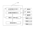
- FIG. 3 is a block diagram showing functional means of the transport vehicle controller.
- the transport vehicle controller 27 includes a travel command assigning unit 71, an empty transported vehicle number grasping unit 72, a standby point selecting unit 73, and a priority storage unit 74.
- the travel command assigning means 71 assigns a travel command for causing the empty transport vehicle closest to each standby point to travel to each standby point (described later).
- the travel command assigning means 71 assigns the travel command not only to the empty transport vehicle that is traveling, but also to the empty transport vehicle that is stopped at the standby point.
- the empty conveyance vehicle number grasping means 72 grasps the number of empty conveyance vehicles to which no travel command is assigned.
- the priority storage unit 74 stores the priority of standby points.
- the standby point selection means 73 selects the same or less standby points as the empty transport vehicle according to the priority stored in the priority storage unit 74 (described later).
- the travel command assigning means 71 issues a travel command to the transport vehicle 3 based on the travel status report from the transport vehicle 3 and the selected standby point information from the standby point selection means 73.
- the empty conveyance vehicle number grasping means 72 grasps the number of empty conveyance vehicles based on the package loading information from the conveyance vehicle 3.
- the standby point selection unit 73 selects a standby point based on the information on the number of empty transport vehicles from the empty transport vehicle number grasping unit 72 and the standby point priority information from the priority storage unit 74.
- FIG. 4 is a flowchart showing control of the standby operation of the transport vehicle in which the transport vehicle controller 27 executes all or at least a part of the transport vehicle standby operation.
- the standby operation of the transport vehicle refers to an operation of causing the empty transport vehicle to travel to a predetermined standby point. This control operation is executed at a predetermined timing.
- the predetermined timing may be a constant cycle, or may be a different cycle depending on the situation. Moreover, you may perform as needed at the timing when a new empty conveyance vehicle generate
- step S1 it is checked whether or not the ratio of empty transport vehicles is greater than or equal to a set value in a specific area (for example, one bay). If it is less than the set value, the control operation is terminated. This is because this control operation does not work effectively when the ratio of empty transport vehicles is not so high.
- step S2 If it is greater than the set value, go to step S2.
- step S2 an empty conveyance vehicle is searched and the number and position of empty conveyance vehicles are specified. This function is realized by the empty conveyance vehicle number grasping means 72.
- step S3 a high-priority standby point that is a target of the transport vehicle call is selected.
- the number of high-priority standby points is set equal to or less than the number of empty transport vehicles in the control area. This function is realized by the standby point selection means 73.
- step S4 target standby point switching is executed.
- the standby point with the highest priority is first selected as a target, and the target standby points are switched in the order of higher priority from the next. This function is realized by the standby point selection means 73.
- step S5 it is determined whether or not the empty transport vehicle is stopped at the target standby point. This function is realized by the standby point selection means 73. If stopped, the process proceeds to step S9.
- step S6 it is determined whether an empty transport vehicle is approaching the target standby point. This function is realized by the standby point selection means 73. When not approaching, it transfers to step S9.
- step S7 it is determined whether or not the nearest transport vehicle is in an empty state. This function is realized by the empty conveyance vehicle number grasping means 72. If it is not empty, the process proceeds to step S9.
- step S8 If it is empty, go to step S8.
- an empty transport vehicle is called into the target standby point. Specifically, a travel command to the target standby point is assigned to the empty transport vehicle closest to the target standby point. This function is realized by the travel command assigning means 71.
- the empty transport vehicles to be allocated include not only the empty transport vehicles that are running but also the empty transport vehicles that are stopped at other standby points.
- step S9 it is determined whether or not empty transport vehicles are stopped at all standby points. This function is realized by the standby point selection means 73. When it is stopped, the control operation is finished. If not, the process returns to step S4.
- FIG. 5 is a schematic guided vehicle system 51 prepared for specifically explaining the above control operation.
- the transport vehicle system 51 includes a transport track 52 and a plurality of transport vehicles (a first transport vehicle 53a, a second transport vehicle 53b, and a third transport vehicle 53c).
- the conveyance track 52 has a large loop 52a that can circulate in one direction, and further has a small loop 52b that can circulate using only a part of the large loop 52a.
- a plurality of stop points 54 are provided on the transport track 52. In FIG. 5, three of the stop points 54 are illustrated as a first standby point 54A, a second standby point 54B, and a third standby point 54C.
- the first standby point 54A is provided in the small loop 52b
- the second standby point 54B is provided in the large loop 52a.
- the third standby point 54C is provided downstream of the second standby point 54B in the traveling direction in the large loop 52a.
- the priority is set higher in the order of the first standby point 54A, the second standby point 54B, and the third standby point 54C.
- a first transport vehicle 53 a, a second transport vehicle 53 b, and a third transport vehicle 53 c exist on the transport track 52 as empty transport vehicles.
- the first transport vehicle 53a is stopped at the first standby point 54A
- the second transport vehicle 53b is stopped at the second standby point 54B.
- the third transport vehicle 53c is located on the downstream side in the traveling direction from the first standby point 54A in the small loop 52b, and has just finished unloading and is an empty transport vehicle.
- step S1 it is determined whether or not the ratio of empty transport vehicles is equal to or greater than a set value. In this embodiment, the description will be continued on the assumption that the set value is exceeded.
- step S2 an empty conveyance vehicle is searched, and the presence and position of the first conveyance vehicle 53a, the second conveyance vehicle 53b, and the third conveyance vehicle 53c are confirmed.
- step S3 since there are three empty transport vehicles, the same number of three locations, specifically, the first standby point 54A, the second standby point 54B, and the third standby point 54C are selected. More specifically, the third standby point 54C is added to the high priority standby point list.
- step S4 the first standby point 54A is selected as the target standby point.
- step S5 since the first transport vehicle 53a is stopped at the first standby point 54A, the process proceeds to step S9.
- step S9 since the empty transport vehicle is not stopped at all the standby points (the empty transport vehicle is not stopped at the third standby point 54C), the process returns to step S4.
- step S4 the target is switched to the second standby point 54B.
- step S5 since the second transport vehicle 53b is stopped at the second standby point 54B, the process proceeds to step S9.
- step S9 since the empty transport vehicle is not stopped at all the standby points (the empty transport vehicle is not stopped at the third standby point 54C), the process returns to step S4.
- step S4 switching to the third standby point 54C is performed.
- step S5 since there is no empty transport vehicle stopped at the third standby point 54C, the process proceeds to step S6.
- step S6 since the empty conveyance vehicle has not approached, it transfers to step S7.
- step S7 since the 2nd conveyance vehicle 53b which is the nearest conveyance vehicle is vacant, it transfers to step S8.
- step S8 the second transport vehicle 53b is called into the third standby point 54C. Specifically, a travel command up to the third standby point 54C is assigned to the second transport vehicle 53b. As a result, the second transport vehicle 53b travels from the second standby point 54B to the third standby point 54C.
- step S9 the process proceeds to step S9 and further returns to step S4.
- step S4 the target is switched to the first standby point 54A.
- step S5 since the first transport vehicle 53a is stopped at the first standby point 54A, the process proceeds to step S9.
- step S9 since the empty transport vehicle is not stopped at all the standby points (the empty transport vehicle is not stopped at the second standby point 54B), the process returns to step S4.
- step S4 the target is switched to the second standby point 54B.
- step S5 since there is no empty transport vehicle stopped at the second standby point 54B, the process proceeds to step S6.
- step S6 since the empty conveyance vehicle has not approached, it transfers to step S7.
- step S7 since the first transport vehicle 53a which is the nearest transport vehicle is vacant, the process proceeds to step S8.
- step S8 the first transport vehicle 53a is called into the second standby point 54B. Specifically, a travel command up to the second standby point 54B is assigned to the first transport vehicle 53a. As a result, the first transport vehicle 53a travels from the first standby point 54A to the second standby point 54B.
- step S9 the process proceeds to step S9 and further returns to step S4.
- step S4 the target is switched to the third standby point 54C.
- step S5 since the second transport vehicle 53b is stopped at the second standby point 54B, the process proceeds to step S9.
- step S9 since the empty transport vehicle is not stopped at all the standby points (the empty transport vehicle is not stopped at the first standby point 54A), the process returns to step S4.
- step S4 the target is switched to the first standby point 54A.
- step S5 since there is no empty transport vehicle stopped at the first waiting point 54A, the process proceeds to step S6.
- step S6 since the empty conveyance vehicle has not approached, it transfers to step S7.
- step S7 since the 3rd conveyance vehicle 53c which is the nearest conveyance vehicle is vacant, it transfers to step S8.
- step S8 the third transport vehicle 53c is called into the first standby point 54A. Specifically, a travel command up to the first standby point 54A is assigned to the third transport vehicle 53c. As a result, the third transport vehicle 53c travels to the first standby point 54A.
- step S9 it is confirmed that the empty transport vehicle is stopped at all the standby points, and the control operation ends.
- the second transport vehicle 53b travels to the third standby point 54C
- the first transport vehicle 53a travels to the second standby point 54B
- the third transport vehicle 53c travels to the first standby point 54A.
- the third transport vehicle 53c (a transport vehicle that does not stop at the standby point) is assigned a travel command up to the third standby point 54C (a standby point where the empty transport vehicle does not stop). Therefore, the third transport vehicle 53c drives the first transport vehicle 53a and the second transport vehicle 53b out of the first standby point 54A and the second standby point 54B.
- FIG. 6 is a schematic guided vehicle system 61 prepared for specifically explaining the control operation.
- the transport vehicle system 61 includes a transport track 62 and a plurality of transport vehicles (a first transport vehicle 63a, a second transport vehicle 63b, and a third transport vehicle 63c).
- the conveyance track 62 has a large loop 62a that can circulate in one direction, and further has a small loop 62b that can circulate using only a part of the large loop 62a.
- a plurality of stop points 64 are provided on the transport track 62. In FIG. 6, three of the stop points 64 are illustrated as a first standby point 64A, a second standby point 64B, and a third standby point 64C.
- the first waiting point 64A is provided in the small loop 52b, and the second waiting point 64B is provided in the large loop 52a.
- the third standby point 64C is provided upstream of the second standby point 64B in the traveling direction in the large loop 52a. Note that the priority is set higher in the order of the first standby point 64A, the second standby point 64B, and the third standby point 64C.
- first transport vehicle 63 a In the state shown in FIG. 6, there are a first transport vehicle 63 a, a second transport vehicle 63 b, and a third transport vehicle 63 c as empty transport vehicles on the transport track 62.
- the first transport vehicle 63a is stopped at the first standby point 64A
- the second transport vehicle 63b is stopped at the second standby point 64B
- the third transport vehicle 63c is stopped at the third standby point 64C.
- a transport request is issued from the stop point 64D (a point upstream of the second standby point 64B in the traveling direction)
- a transport command is assigned to the first transport vehicle 63a.
- the first transport vehicle 63a travels from the first standby point 64A to the stop point 64D, and performs a cargo grasping operation.
- step S1 it is determined whether or not the ratio of empty transport vehicles is equal to or greater than a set value. In this embodiment, the description will be continued on the assumption that the set value is exceeded.
- step S2 an empty transport vehicle is searched to confirm the presence and position of the second transport vehicle 63b and the third transport vehicle 63c.
- step S3 since there are two empty transport vehicles, the same two places, specifically, the first standby point 64A and the second standby point 54B are selected. More specifically, the third standby point 54C is deleted from the list of standby points with high priority already.
- step S4 the first waiting point 64A is selected as a target.
- step S5 since there is no empty transport vehicle stopped at the first standby point 64A, the process proceeds to step S6.
- step S6 since the empty conveyance vehicle has not approached, it transfers to step S7.
- step S7 since the 3rd conveyance vehicle 63c which is the nearest conveyance vehicle is vacant, it transfers to step S8.
- step S8 the third transport vehicle 63c is called into the first standby point 64A. Specifically, a travel command up to the first standby point 64A is assigned to the third transport vehicle 63c. As a result, the third transport vehicle 63c travels from the third standby point 64C to the first standby point 64A.
- step S4 the target is switched to the second standby point 64B.
- step S4 since the second transport vehicle 63b is stopped at the second standby point 64B, the process proceeds to step S9.
- step S9 it is confirmed that the empty transport vehicle is stopped at all the standby points, and the control operation ends.
- the transport vehicle system 51 includes a transport track 52 having a plurality of standby points 54A to 54C, a plurality of transport vehicles 3 that travel on the transport track 52, and a transport vehicle controller that can assign a travel command to the transport vehicle 3. 27.
- the transport vehicle controller 27 includes travel command assigning means 71.
- the travel command assigning means 71 assigns a travel command for causing the empty transport vehicle closest to each standby point to travel to each standby point.
- a travel command for traveling to each standby point 54A to 54C is assigned to the empty transport vehicle closest to each standby point, so that the traveling efficiency of the transport vehicle 3 is improved.
- the transport vehicle controller 27 further includes empty transport vehicle number grasping means 72 and standby point selecting means 73.
- the empty conveyance vehicle number grasping means 72 grasps the number of empty conveyance vehicles to which no travel command is assigned.
- the standby point selection means function selects the same or less standby points as the empty transport vehicle. Since the transport controller 27 assigns a traveling command to the standby points 54A to 54C that are equal to or less than the number of empty transport vehicles, it is difficult to assign far standby points to each transport vehicle 3. Therefore, the traveling efficiency of the transport vehicle 3 is improved.
- the closest first standby point 54A is allocated to the third transport vehicle 53c without the second standby point 54B and the third standby point 54C being allocated.
- the travel command assigning means 71 assigns the travel command not only to the empty transport vehicle that is traveling but also to the empty transport vehicle that is stopped at the standby points 54A to 54C. Since the travel command is also assigned to the empty transport vehicle that has already stopped at the standby points 54A to 54C, the travel of the transport vehicle 3 in the transport vehicle system 1 is compared with the case where the travel command is assigned only to the empty transport vehicle that is traveling. Efficiency is improved. As a specific example, in the transport vehicle system 51 shown in FIG. 5, the travel command is assigned not only to the traveling third transport vehicle 53c but also to the stopped first transport vehicle 53a and the second transport vehicle 53b.
- the transport vehicle controller 27 further includes a priority storage unit 74 that stores the priorities of the standby points 54A to 54C.
- the standby point selection unit 73 selects a standby point according to the priority stored in the priority storage unit 74. In this system, since the standby point is determined according to the priority, the standby point can be determined quickly.
- the transport vehicle control method includes the following steps in a transport vehicle system 1 having a transport track 52 having a plurality of standby points 54A to 54C and a plurality of transport vehicles 3 traveling on the transport track 52. .
- Step S2 grasping the number of empty transport vehicles for which the number of empty transport vehicles to which no travel command is assigned is grasped
- step S3 Standby point selection step
- step S8 for assigning a running command for causing the empty transport vehicle closest to each waiting point to travel to each waiting point.
- a traveling command to the same or less standby points as the number of empty transport vehicles is assigned, so that it is difficult for remote transport points to be assigned to each transport vehicle 3. Therefore, the traveling efficiency of the transport vehicle 3 is improved.
- the layout and control system of the transport vehicle system are not limited to the first embodiment and the second embodiment. Further, the type of equipment to which the transport vehicle system is applied is not limited to the above embodiment.
- the present invention relates to a transport vehicle system and a transport vehicle control method, and is particularly applicable to a transport vehicle system and a transport vehicle control method in which a plurality of transport vehicles travel on a route having a plurality of standby points.
Landscapes
- Engineering & Computer Science (AREA)
- Aviation & Aerospace Engineering (AREA)
- Radar, Positioning & Navigation (AREA)
- Remote Sensing (AREA)
- Physics & Mathematics (AREA)
- General Physics & Mathematics (AREA)
- Automation & Control Theory (AREA)
- Control Of Position, Course, Altitude, Or Attitude Of Moving Bodies (AREA)
- Warehouses Or Storage Devices (AREA)
Abstract
複数の待機ポイントを有する経路を複数の搬送車が走行する搬送車システムおよび搬送車制御方法において、搬送車の走行効率を向上させる。搬送車システム(1)は、複数の待機ポイントを有する経路と、経路を走行する複数の搬送車と、搬送車に走行指令を割り付けることができる搬送車コントローラとを備えている。搬送車コントローラは、走行指令割り付け機能(ステップS8)を有する。走行指令割り付け機能(S8)は、各待機ポイントに最も近い空き搬送車に各待機ポイントまで走行させる走行指令を割り付ける。
Description
本発明は、搬送車システムおよび搬送車制御方法に関し、特に複数の待機ポイントを有する経路を複数の搬送車が走行する搬送車システムおよび搬送車制御方法に関する。
従来、予め定まった経路と、経路上に設けられた複数のステーションと、経路に沿って走行して物品を搬送する複数の搬送車とを有する搬送車システムが知られている。搬送車システムでは、ステーションと搬送車との間では、荷つかみ(搬送車にステーションから物品が積み込まれること)や、荷おろし(搬送車からステーションに物品が積み出されること)が行われる。このシステムでは、あるステーションから物品の荷つかみ要求が発生すると、最も近い位置にある空き搬送車に、そのステーションに移動して物品を受け取るように搬送指令を割り付ける。最も近い空き搬送車を選択するのは、物品を迅速に搬送するためである。
搬送車は、搬送指令を実行後に空き状態になる。空き搬送車は、経路に設けられた待機ポイントに停止させられ、次の搬送指令に備える(例えば、特許文献1を参照。)。
また、他の搬送車によって待機ポイントを追い出された空き搬送車も、次の待機ポイントに移動してそこで停止する。
また、他の搬送車によって待機ポイントを追い出された空き搬送車も、次の待機ポイントに移動してそこで停止する。
一般に、搬送効率を向上させるために、荷つかみ指令発生頻度が高い装置付近に待機ポイントが設置されている。
また、待機ポイントにはそれぞれ優先度を設定しており、空き搬送車は優先度の高い待機ポイントに向かって走行するようになっている。しかし、この従来の技術では、空き搬送車が優先度の高い待機ポイントを目指して走行するので、途中の待機ポイントで待機している他の搬送車が追い出される。そのため、システム全体において搬送車の走行効率が低下することがある。
本発明の課題は、複数の待機ポイントを有する経路を複数の搬送車が走行する搬送車システムおよび搬送車制御方法において、搬送車の走行効率を向上させることにある。
本発明に係る搬送車システムは、複数の待機ポイントを有する経路と、経路を走行する複数の搬送車と、搬送車に走行指令を割り付けることができるコントローラとを備えている。コントローラは、走行指令割り付け手段を有する。走行指令割り付け手段は、各待機ポイントに最も近い空き搬送車に各待機ポイントまで走行させる走行指令を割り付ける。
このシステムでは、各待機ポイントに最も近い空き搬送車に各待機ポイントまで走行させる走行指令が割り付けられるので、搬送車の走行効率が向上する。
このシステムでは、各待機ポイントに最も近い空き搬送車に各待機ポイントまで走行させる走行指令が割り付けられるので、搬送車の走行効率が向上する。
コントローラは、空き搬送車数把握手段と、待機ポイント選択手段とをさらに有していてもよい。空き搬送車数把握手段は、走行指令が割り付けられていない空き搬送車の数を把握する。待機ポイント選択手段は、空き搬送車と同数または未満の待機ポイントを選択する。
このシステムでは、コントローラが空き搬送車数に対し同数または未満の待機ポイントへの走行指令を割り付けるので、各搬送車に遠くの待機ポイントが割り付けられにくい。したがって、搬送車の走行効率が向上する。
このシステムでは、コントローラが空き搬送車数に対し同数または未満の待機ポイントへの走行指令を割り付けるので、各搬送車に遠くの待機ポイントが割り付けられにくい。したがって、搬送車の走行効率が向上する。
走行指令割り付け手段は、走行中の空き搬送車のみならず、待機ポイントに停止中の空き搬送車にも走行指令を割り付けるようになっていてもよい。
このシステムでは、既に待機ポイントで停止している搬送車にも走行指令を割り付けるので、走行中の搬送車にのみ走行指令を割り付ける場合に比べて、システムにおける搬送車の走行効率が向上する。
このシステムでは、既に待機ポイントで停止している搬送車にも走行指令を割り付けるので、走行中の搬送車にのみ走行指令を割り付ける場合に比べて、システムにおける搬送車の走行効率が向上する。
コントローラは、待機ポイントの優先度を記憶する優先度記憶手段をさらに有している。待機ポイント選択手段は、優先度記憶手段に記憶された優先度に従って待機ポイントを選択するようになっていてもよい。
このシステムでは、優先度に従って待機ポイントを選択するので、待機ポイントを迅速に決定できる。
このシステムでは、優先度に従って待機ポイントを選択するので、待機ポイントを迅速に決定できる。
本発明の他の見地に係る搬送車制御方法は、複数の待機ポイントを有する経路と、経路を走行する複数の搬送車とを有する搬送車システムにおいて、以下のステップを備えている。
◎走行指令が割り付けられていない空き搬送車の数を把握する空き搬送車数把握ステップ
◎空き搬送車と同数または未満の待機ポイントを選択する待機ポイント選択ステップ
◎各待機ポイントに最も近い空き搬送車に各待機ポイントまで走行させる走行指令を割り付ける走行指令割り付けステップ
この方法では、空き搬送車数に対して同数または未満の待機ポイントへの走行指令が割り付けられるので、各搬送車に遠くの待機ポイントが割り付けられにくい。したがって、搬送車の走行効率が向上する。
◎走行指令が割り付けられていない空き搬送車の数を把握する空き搬送車数把握ステップ
◎空き搬送車と同数または未満の待機ポイントを選択する待機ポイント選択ステップ
◎各待機ポイントに最も近い空き搬送車に各待機ポイントまで走行させる走行指令を割り付ける走行指令割り付けステップ
この方法では、空き搬送車数に対して同数または未満の待機ポイントへの走行指令が割り付けられるので、各搬送車に遠くの待機ポイントが割り付けられにくい。したがって、搬送車の走行効率が向上する。
本発明に係る搬送車システムおよび搬送車制御方法では、複数の待機ポイントを有する経路を複数の搬送車が走行する搬送車システムにおいて、搬送車の走行効率が向上する。
1.搬送車システムのレイアウト
本発明の一実施形態としての搬送車システム1は、定められた経路上に複数の搬送車3を走行させるためのシステムである。搬送車3は、経路上を走行し、上位のコントローラ(後述)によって割り付けられる搬送指令に従い、目的の場所から物品を積み込み、次に搬送先の場所まで走行して物品を搬送先の場所に積み出す。搬送車の種類は、天井走行車、無軌道で走行する無人搬送車や有軌道台車のいずれであってもよい。
本発明の一実施形態としての搬送車システム1は、定められた経路上に複数の搬送車3を走行させるためのシステムである。搬送車3は、経路上を走行し、上位のコントローラ(後述)によって割り付けられる搬送指令に従い、目的の場所から物品を積み込み、次に搬送先の場所まで走行して物品を搬送先の場所に積み出す。搬送車の種類は、天井走行車、無軌道で走行する無人搬送車や有軌道台車のいずれであってもよい。
図1に、搬送車システム1のレイアウトを示す。搬送車システム1は、複数の周回走行路5と、複数の周回走行路5を結ぶ基幹走行路7とを有している。基幹走行路7は全体で一つの周回経路となっている。周回走行路5に沿って複数の処理装置9が設けられ、基幹走行路7に沿って複数のストッカ11が設けられている。ストッカ11は、周回走行路5における処理装置9群間でのバッファの機能を実現している。
処理装置9およびストッカ11等の設備には、設備内に物品を搬入するための入庫ポート13と、設備から搬送車3に物品を荷つかみするための出庫ポート15とが設けてある。なお入庫ポート13と出庫ポート15とは兼用されていてもよい。
2.搬送車システムの制御系
図2に、搬送車システム1の制御系19を示す。この制御系19は、製造コントローラ21と、物流コントローラ23と、ストッカコントローラ25と、搬送車コントローラ27とを有している。物流コントローラ23は、ストッカコントローラ25および搬送車コントローラ27の上位のコントローラである。搬送車コントローラ27は、複数の搬送車3を管理し、これらに搬送指令を割り付ける割り付け機能を有している。なお、「搬送指令」は、走行に関する指令や、荷つかみ位置と荷おろし位置に関する指令を含んでいる。
図2に、搬送車システム1の制御系19を示す。この制御系19は、製造コントローラ21と、物流コントローラ23と、ストッカコントローラ25と、搬送車コントローラ27とを有している。物流コントローラ23は、ストッカコントローラ25および搬送車コントローラ27の上位のコントローラである。搬送車コントローラ27は、複数の搬送車3を管理し、これらに搬送指令を割り付ける割り付け機能を有している。なお、「搬送指令」は、走行に関する指令や、荷つかみ位置と荷おろし位置に関する指令を含んでいる。
製造コントローラ21は、各処理装置9との間で通信することができる。処理装置9は、処理が終了した物品の搬送要求(荷つかみ要求・荷おろし要求)を製造コントローラ21に送信する。
製造コントローラ21は、処理装置9からの搬送要求を物流コントローラ23に送信し、物流コントローラ23は報告を製造コントローラ21に送信する。
物流コントローラ23は、製造コントローラ21から搬送要求を受けると、ストッカ11での入庫や出庫が伴っている場合、所定のタイミングで入庫や出庫指令をストッカコントローラ25へ送信する。そして、ストッカコントローラ25は、これに応じて入庫や出庫指令をストッカ11へ送信する。物流コントローラ23は、さらに、製造コントローラ21から搬送要求を受け取ると、それを搬送指令に変換し、搬送車3への搬送指令割り付け動作を行う。
搬送車コントローラ27は、搬送指令を作成するために各搬送車3と連続的に通信して、各搬送車3から送信された位置データをもとにその位置情報を得ている。位置情報を取得する例としては、以下の2つがある。
・周回走行路5に複数のポイントを設定しておき、搬送車3がポイントを通過したときに通過信号を搬送車コントローラ27に送信させるようにしておく。そして、搬送車コントローラ27が、搬送車3が直近に通過したポイントがどのポイントであるかと、ポイントを通過した時刻を記憶する。そして、そのポイント区間の規定速度と時間をもとに搬送車3の位置を演算して求める。
・例えばエンコーダを搬送車3に設けておいて、ポイントを通過してからの走行距離を搬送車3から搬送車コントローラ27へ位置データとして送信させ、搬送車コントローラ27がこれによって搬送車3の位置を把握する。
搬送車コントローラ27のメモリ(図示せず)には、搬送軌道のレイアウトデータが記憶されている。レイアウトデータは、複数の待機ポイント(後述)およびそれらの優先度に関する情報を含んでいる。
搬送車3は、制御部とメモリを含むコントローラ(図示せず)を有している。搬送車3のコントローラは、CPU、RAM、ROM等からなりプログラムを実行するコンピュータである。搬送車3のコントローラは、搬送車コントローラ27と交信可能である。搬送車3は、メモリ内にルートマップを有しており、ルートマップに記載の座標と自機の内部座標(エンコーダによって求めた座標)とを比較しながら走行を続ける。
図3を用いて、搬送車コントローラ27が実現する各機能を説明する。図3は、搬送車コントローラの機能手段を示すブロック図である。
搬送車コントローラ27は、走行指令割り付け手段71と、空き搬送車数把握手段72と、待機ポイント選択手段73と、優先度記憶部74とを有している。走行指令割り付け手段71は、各待機ポイントに最も近い空き搬送車に各待機ポイントまで走行させる走行指令を割り付ける(後述)。走行指令割り付け手段71は、走行中の空き搬送車のみならず、待機ポイントに停止中の空き搬送車にも走行指令を割り付ける。空き搬送車数把握手段72は、走行指令が割り付けられていない空き搬送車の数を把握する。優先度記憶部74は、待機ポイントの優先度を記憶している。待機ポイント選択手段73は、優先度記憶部74に記憶された優先度に従って、空き搬送車と同数または未満の待機ポイントを選択する(後述)。
図3から明らかなように、走行指令割り付け手段71は、搬送車3からの走行状況報告と、待機ポイント選択手段73からの選択された待機ポイント情報とに基づいて、搬送車3に走行指令を割り付ける。空き搬送車数把握手段72は、搬送車3からの荷物搭載情報に基づいて空き搬送車数を把握する。待機ポイント選択手段73は、空き搬送車数把握手段72からの空き搬送車数情報と、優先度記憶部74からの待機ポイント優先度情報に基づいて、待機ポイントを選択する。
3.搬送車コントローラによる搬送車待機動作の制御
図4は、搬送車コントローラ27が全部または少なくとも一部を実行する搬送車の待機動作の制御を示すフローチャートである。搬送車の待機動作とは、空き搬送車を所定の待機ポイントまで走行させる動作をいう。
この制御動作は、所定のタイミングで実行される。所定のタイミングとは一定の周期であってもよいし、状況に応じて異なる周期であってもよい。また、必要に応じて、新たに空き搬送車が発生したタイミングで実行されてもよい。
図4は、搬送車コントローラ27が全部または少なくとも一部を実行する搬送車の待機動作の制御を示すフローチャートである。搬送車の待機動作とは、空き搬送車を所定の待機ポイントまで走行させる動作をいう。
この制御動作は、所定のタイミングで実行される。所定のタイミングとは一定の周期であってもよいし、状況に応じて異なる周期であってもよい。また、必要に応じて、新たに空き搬送車が発生したタイミングで実行されてもよい。
ステップS1では、特定の領域(例えば、一つのベイ)において空き搬送車の割合が設定値以上か否かを調べる。設定値未満の場合は制御動作を終了する。空き搬送車の割合があまり高くない場合は、本制御動作が有効に働かないからである。
設定値以上の場合はステップS2に移行する。ステップS2では、空き搬送車が検索されて、空き搬送車の数や位置が特定される。この機能は、空き搬送車数把握手段72によって実現される。
ステップS3では、搬送車呼び込みの対象となる高優先の待機ポイントが選択される。このとき、高優先の待機ポイントの数は、制御エリア内の空き搬送車の数と同じかまたはそれよりも少なく設定される。この機能は、待機ポイント選択手段73によって実現される。
ステップS4では、対象待機ポイント切り換えが実行される。対象待機ポイント切り換えとは、最初に最も優先度の高い待機ポイントを対象として選択して、次からは優先度の高い順に対象となる待機ポイントを切り換えていく動作を行う。この機能は、待機ポイント選択手段73によって実現される。
ステップS5では、対象待機ポイントに空き搬送車が停止しているか否かが判断される。この機能は、待機ポイント選択手段73によって実現される。停止している場合は、ステップS9に移行する。
停止していない場合は、ステップS6に移行する。ステップS6では、対象待機ポイントに空き搬送車が接近しているか否かが判断される。この機能は、待機ポイント選択手段73によって実現される。接近していない場合は、ステップS9に移行する。
接近している場合はステップS7に移行する。ステップS7では、最も近い搬送車が空き状態であるか否かが判断される。この機能は、空き搬送車数把握手段72によって実現される。空き状態でない場合は、ステップS9に移行する。
空き状態の場合はステップS8に移行する。ステップS8では、対象待機ポイントに空き搬送車を呼び込む。具体的には、対象待機ポイントに最も近い空き搬送車に対象待機ポイントまでの走行指令を割り付ける。この機能は、走行指令割り付け手段71によって実現される。この場合、割り付け対象となる空き搬送車は、走行中の空き搬送車のみならず、他の待機ポイントに停止している空き搬送車も含んでいることが好ましい。
ステップS9では、全ての待機ポイントに空き搬送車が停止しているか否かが判断される。この機能は、待機ポイント選択手段73によって実現される。停止している場合は制御動作が終了となる。停止していない場合はステップS4に戻る。
4.第1実施例
図5は、上記制御動作を具体的に説明するために用意した模式的な搬送車システム51である。
図5は、上記制御動作を具体的に説明するために用意した模式的な搬送車システム51である。
この搬送車システム51は、搬送軌道52と、複数の搬送車(第1搬送車53a、第2搬送車53b、第3搬送車53c)とを有している。搬送軌道52は、一方向に循環可能な大ループ52aを有しており、さらに大ループ52a内でその一部のみを利用して循環可能な小ループ52bを有している。搬送軌道52には複数の停止ポイント54が設けられている。また、図5では、停止ポイント54のうち3箇所が第1待機ポイント54A、第2待機ポイント54B、第3待機ポイント54Cとして図示されている。第1待機ポイント54Aは、小ループ52bに設けられており、第2待機ポイント54Bは大ループ52aに設けられている。第3待機ポイント54Cは、大ループ52aにおいて、第2待機ポイント54Bより走行方向下流側に設けられている。なお、第1待機ポイント54A、第2待機ポイント54B、第3待機ポイント54Cの順番で優先度が高く設定されている。
図5に示す状態では、搬送軌道52には、空き搬送車として、第1搬送車53a,第2搬送車53b、第3搬送車53cが存在している。第1搬送車53aは第1待機ポイント54Aに停止しており、第2搬送車53bは第2待機ポイント54Bに停止している。第3搬送車53cは、小ループ52bに内において第1待機ポイント54Aより走行方向下流側に位置しており、たった今荷おろしを終了して空き搬送車になっている。
図4のフローチャートに基づいて搬送車の待機動作の制御を説明する。ステップS1では、空き搬送車の割合が設定値以上か否かが判断される。この実施例では、以後、設定値以上であるとして説明を続ける。ステップS2では、空き搬送車の検索を行い、第1搬送車53a、第2搬送車53b、および第3搬送車53cの存在と位置を確認する。ステップS3では、空き搬送車の数が3台なので、同数の3箇所、具体的には、第1待機ポイント54A、第2待機ポイント54Bおよび第3待機ポイント54Cを選択する。より具体的には、高優先の待機ポイントのリストに第3待機ポイント54Cを追加する。
ステップS4では、第1待機ポイント54Aを対象待機ポイントして選択する。ステップS5では、第1搬送車53aが第1待機ポイント54Aに停止しているのでステップS9に移行する。ステップS9では、全ての待機ポイントに空き搬送車は停止してない(第3待機ポイント54Cに空き搬送車が停止していない)ので、ステップS4に戻る。
ステップS4では、対象を第2待機ポイント54Bに切り換える。ステップS5では、第2搬送車53bが第2待機ポイント54Bに停止しているのでステップS9に移行する。ステップS9では、全ての待機ポイントに空き搬送車は停止してない(第3待機ポイント54Cに空き搬送車が停止していない)ので、ステップS4に戻る。
ステップS4では、第3待機ポイント54Cに切り換える。ステップS5では、第3待機ポイント54Cに停止している空き搬送車は無いので、ステップS6に移行する。ステップS6では、空き搬送車が接近していないのでステップS7に移行する。ステップS7では、最寄りの搬送車である第2搬送車53bが空いているのでステップS8に移行する。ステップS8では、第2搬送車53bを第3待機ポイント54Cに呼び込む。具体的には、第2搬送車53bに第3待機ポイント54Cまでの走行指令を割り付ける。その結果、第2搬送車53bは第2待機ポイント54Bから第3待機ポイント54Cまで走行する。
次に、ステップS9に移行し、さらにステップS4に戻る。ステップS4では、対象を第1待機ポイント54Aに切り換える。ステップS5では、第1搬送車53aが第1待機ポイント54Aに停止しているのでステップS9に移行する。ステップS9では、全ての待機ポイントに空き搬送車は停止してない(第2待機ポイント54Bに空き搬送車が停止していない)ので、ステップS4に戻る。
ステップS4では、対象を第2待機ポイント54Bに切り換える。ステップS5では、第2待機ポイント54Bに停止している空き搬送車は無いので、ステップS6に移行する。ステップS6では、空き搬送車が接近していないのでステップS7に移行する。ステップS7では、最寄りの搬送車である第1搬送車53aが空いているのでステップS8に移行する。ステップS8では、第1搬送車53aを第2待機ポイント54Bに呼び込む。具体的には、第1搬送車53aに第2待機ポイント54Bまでの走行指令を割り付ける。その結果、第1搬送車53aは第1待機ポイント54Aから第2待機ポイント54Bまで走行する。
次に、ステップS9に移行し、さらにステップS4に戻る。ステップS4では、対象を第3待機ポイント54Cに切り換える。ステップS5では、第2搬送車53bが第2待機ポイント54Bに停止しているのでステップS9に移行する。ステップS9では、全ての待機ポイントに空き搬送車は停止してない(第1待機ポイント54Aに空き搬送車が停止していない)ので、ステップS4に戻る。
ステップS4では、対象を第1待機ポイント54Aに切り換える。ステップS5では、第1待機ポイント54Aに停止している空き搬送車は無いので、ステップS6に移行する。ステップS6では、空き搬送車が接近していないのでステップS7に移行する。ステップS7では、最寄りの搬送車である第3搬送車53cが空いているのでステップS8に移行する。ステップS8では、第3搬送車53cを第1待機ポイント54Aに呼び込む。具体的には、第3搬送車53cに第1待機ポイント54Aまでの走行指令を割り付ける。その結果、第3搬送車53cは第1待機ポイント54Aまで走行する。
ステップS9では、全ての待機ポイントに空き搬送車が停止していることが確認され、制御動作が終了する。
以上に述べた制御動作では、第2搬送車53bが第3待機ポイント54Cに走行し、第1搬送車53aが第2待機ポイント54Bに走行し、第3搬送車53cが第1待機ポイント54Aに走行する。従来では、例えば、第3搬送車53c(待機ポイントに停止してない搬送車)が第3待機ポイント54C(空き搬送車が停止していない待機ポイント)までの走行指令を割り付けられる。そのため、第3搬送車53cが第1搬送車53aおよび第2搬送車53bを第1待機ポイント54Aおよび第2待機ポイント54Bから追い出していた。本発明に係る実施形態ではそのような追い出しが行われないため、システム全体の搬送効率が向上する。
5.第2実施例
図6は、上記制御動作を具体的に説明するために用意した模式的な搬送車システム61である。この搬送車システム61は、搬送軌道62と、複数の搬送車(第1搬送車63a、第2搬送車63b、第3搬送車63c)とを有している。搬送軌道62は、一方向に循環可能な大ループ62aを有しており、さらに大ループ62a内でその一部のみを利用して循環可能な小ループ62bを有している。搬送軌道62には複数の停止ポイント64が設けられている。また、図6では、停止ポイント64のうち3箇所が第1待機ポイント64A、第2待機ポイント64B、第3待機ポイント64Cとして図示されている。第1待機ポイント64Aは、小ループ52bに設けられており、第2待機ポイント64Bは大ループ52aに設けられている。第3待機ポイント64Cは、大ループ52aにおいて、第2待機ポイント64Bより走行方向上流側に設けられている。なお、第1待機ポイント64A、第2待機ポイント64B、第3待機ポイント64Cの順番で優先度が高く設定されている。
図6は、上記制御動作を具体的に説明するために用意した模式的な搬送車システム61である。この搬送車システム61は、搬送軌道62と、複数の搬送車(第1搬送車63a、第2搬送車63b、第3搬送車63c)とを有している。搬送軌道62は、一方向に循環可能な大ループ62aを有しており、さらに大ループ62a内でその一部のみを利用して循環可能な小ループ62bを有している。搬送軌道62には複数の停止ポイント64が設けられている。また、図6では、停止ポイント64のうち3箇所が第1待機ポイント64A、第2待機ポイント64B、第3待機ポイント64Cとして図示されている。第1待機ポイント64Aは、小ループ52bに設けられており、第2待機ポイント64Bは大ループ52aに設けられている。第3待機ポイント64Cは、大ループ52aにおいて、第2待機ポイント64Bより走行方向上流側に設けられている。なお、第1待機ポイント64A、第2待機ポイント64B、第3待機ポイント64Cの順番で優先度が高く設定されている。
図6に示す状態では、搬送軌道62には、空き搬送車として、第1搬送車63a,第2搬送車63b、第3搬送車63cが存在している。第1搬送車63aは第1待機ポイント64Aに停止しており、第2搬送車63bは第2待機ポイント64Bに停止しており、第3搬送車63cは第3待機ポイント64Cに停止している。この状態で、停止ポイント64D(第2待機ポイント64Bの走行方向上流側のポイント)にからの搬送要求が出されると、第1搬送車63aに搬送指令が割り付けられる。その結果、第1搬送車63aは、第1待機ポイント64Aから停止ポイント64Dまで走行して、荷つかみ動作を実行する。
図4のフローチャートに基づいて制御動作を説明する。ステップS1では、空き搬送車の割合が設定値以上か否かが判断される。この実施例では、以後、設定値以上であるとして説明を続ける。ステップS2では、空き搬送車の検索を行い、第2搬送車63b、および第3搬送車63cの存在と位置を確認する。ステップS3では、空き搬送車の数が2台なので、同数の2箇所、具体的には、第1待機ポイント64Aおよび第2待機ポイント54Bを選択する。より具体的には、既に高優先の待機ポイントのリストから第3待機ポイント54Cを削除する。
ステップS4では、対象として第1待機ポイント64Aを選択する。ステップS5では、第1待機ポイント64Aに停止している空き搬送車は無いので、ステップS6に移行する。ステップS6では、空き搬送車が接近していないのでステップS7に移行する。ステップS7では、最寄りの搬送車である第3搬送車63cが空いているのでステップS8に移行する。ステップS8では、第3搬送車63cを第1待機ポイント64Aに呼び込む。具体的には、第3搬送車63cに第1待機ポイント64Aまでの走行指令を割り付ける。その結果、第3搬送車63cは第3待機ポイント64Cから第1待機ポイント64Aまで走行する。
ステップS4では、対象を第2待機ポイント64Bに切り換える。ステップS4では、第2搬送車63bが第2待機ポイント64Bに停止しているのでステップS9に移行する。ステップS9では、全ての待機ポイントに空き搬送車が停止していることが確認され、制御動作が終了する。
6.特徴
以下、第1実施形態(図5)としての搬送車システム51を用いて、本発明に係る実施形態の特徴を説明する。
(1)搬送車システム51は、複数の待機ポイント54A~54Cを有する搬送軌道52と、搬送軌道52を走行する複数の搬送車3と、搬送車3に走行指令を割り付けることができる搬送車コントローラ27とを備えている。搬送車コントローラ27は、走行指令割り付け手段71を有する。走行指令割り付け手段71は、各待機ポイントに最も近い空き搬送車に各待機ポイントまで走行させる走行指令を割り付ける。
このシステムでは、各待機ポイントに最も近い空き搬送車に各待機ポイント54A~54Cまで走行させる走行指令が割り付けられるので、搬送車3の走行効率が向上する。
(2)搬送車コントローラ27は、空き搬送車数把握手段72と、待機ポイント選択手段73とをさらに有している。空き搬送車数把握手段72は、走行指令が割り付けられていない空き搬送車の数を把握する。待機ポイント選択手段機能は、空き搬送車と同数または未満の待機ポイントを選択する。
搬送車コントローラ27が空き搬送車数に対して同数または未満の待機ポイント54A~54Cへの走行指令が割り付けられるので、各搬送車3に遠くの待機ポイントが割り付けられにくい。したがって、搬送車3の走行効率が向上する。具体例としては、図5に示す搬送車システム51において、第3搬送車53cには第2待機ポイント54Bや第3待機ポイント54Cが割り付けられることなく、最も近い第1待機ポイント54Aが割り付けられる。
搬送車コントローラ27が空き搬送車数に対して同数または未満の待機ポイント54A~54Cへの走行指令が割り付けられるので、各搬送車3に遠くの待機ポイントが割り付けられにくい。したがって、搬送車3の走行効率が向上する。具体例としては、図5に示す搬送車システム51において、第3搬送車53cには第2待機ポイント54Bや第3待機ポイント54Cが割り付けられることなく、最も近い第1待機ポイント54Aが割り付けられる。
(3)走行指令割り付け手段71は、走行中の空き搬送車のみならず、待機ポイント54A~54Cに停止中の空き搬送車にも走行指令を割り付ける。
既に待機ポイント54A~54Cで停止している空き搬送車にも走行指令が割り付けられるので、走行中の空き搬送車にのみ走行指令を割り付ける場合に比べて、搬送車システム1における搬送車3の走行効率が向上する。具体例としては、図5に示す搬送車システム51において、走行中の第3搬送車53cのみならず、停車中の第1搬送車53aおよび第2搬送車53bにも走行指令が割り付けられる。
既に待機ポイント54A~54Cで停止している空き搬送車にも走行指令が割り付けられるので、走行中の空き搬送車にのみ走行指令を割り付ける場合に比べて、搬送車システム1における搬送車3の走行効率が向上する。具体例としては、図5に示す搬送車システム51において、走行中の第3搬送車53cのみならず、停車中の第1搬送車53aおよび第2搬送車53bにも走行指令が割り付けられる。
(4)搬送車コントローラ27は、待機ポイント54A~54Cの優先度を記憶する優先度記憶部74をさらに有している。待機ポイント選択手段73は、優先度記憶部74に記憶された優先度に従って待機ポイントを選択するようになっている。
このシステムでは、優先度に従って待機ポイントが決定されるので、待機ポイントを迅速に決定できる。
このシステムでは、優先度に従って待機ポイントが決定されるので、待機ポイントを迅速に決定できる。
(5)搬送車制御方法は、複数の待機ポイント54A~54Cを有する搬送軌道52と、搬送軌道52を走行する複数の搬送車3とを有する搬送車システム1において、以下のステップを備えている。
◎走行指令が割り付けられていない空き搬送車の数を把握する空き搬送車数把握ステップ(ステップS2)
◎空き搬送車と同数または未満の待機ポイントを選択する待機ポイント選択ステップ(ステップS3)
◎各待機ポイントに最も近い空き搬送車に各待機ポイントまで走行させる走行指令を割り付ける走行指令割り付けステップ(ステップS8)
この方法では、空き搬送車数に対して同数または未満の待機ポイントへの走行指令が割り付けられるので、各搬送車3に遠くの待機ポイントが割り付けられにくい。したがって、搬送車3の走行効率が向上する。
◎走行指令が割り付けられていない空き搬送車の数を把握する空き搬送車数把握ステップ(ステップS2)
◎空き搬送車と同数または未満の待機ポイントを選択する待機ポイント選択ステップ(ステップS3)
◎各待機ポイントに最も近い空き搬送車に各待機ポイントまで走行させる走行指令を割り付ける走行指令割り付けステップ(ステップS8)
この方法では、空き搬送車数に対して同数または未満の待機ポイントへの走行指令が割り付けられるので、各搬送車3に遠くの待機ポイントが割り付けられにくい。したがって、搬送車3の走行効率が向上する。
7.他の実施形態
以上、本発明の一実施形態について説明したが、本発明は上記実施形態に限定されるものではなく、発明の要旨を逸脱しない範囲で種々の変更が可能である。
以上、本発明の一実施形態について説明したが、本発明は上記実施形態に限定されるものではなく、発明の要旨を逸脱しない範囲で種々の変更が可能である。
搬送車システムのレイアウトおよび制御系は、第1実施形態や第2実施形態に限定されない。また、搬送車システムが適用される設備の種類も前記実施形態に限定されない。
本発明は、搬送車システムおよび搬送車制御方法に関し、特に複数の待機ポイントを有する経路を複数の搬送車が走行する搬送車システムおよび搬送車制御方法に広く適用可能である。
1 搬送車システム
3 搬送車
5 周回走行路
7 基幹走行路
9 処理装置
11 ストッカ
13 入庫ポート
15 出庫ポート
19 制御系
21 製造コントローラ
23 物流コントローラ
25 ストッカコントローラ
27 搬送車コントローラ
51 搬送車システム
52 搬送軌道
52a 大ループ
52b 小ループ
53a 第1搬送車
53b 第2搬送車
53c 第3搬送車
54 停止ポイント
54A 第1待機ポイント
54B 第2待機ポイント
54C 第3待機ポイント
61 搬送車システム
62 搬送軌道
62a 大ループ
62b 小ループ
63a 第1搬送車
63b 第2搬送車
63c 第3搬送車
64 停止ポイント
64A 第1待機ポイント
64B 第2待機ポイント
64C 第3待機ポイント
64D 停止ポイント
71 走行指令割り付け手段
72 空き搬送車数把握手段
73 待機ポイント選択手段
74 優先度記憶部
Claims (5)
- 複数の待機ポイントを有する経路と、
前記経路を走行する複数の搬送車と、
前記搬送車に走行指令を割り付けることができるコントローラとを備え、
前記コントローラは、各待機ポイントに最も近い空き搬送車に各待機ポイントまで走行させる走行指令を割り付ける走行指令割り付け手段とを有する、
搬送車システム。 - 前記コントローラは、走行指令が割り付けられていない空き搬送車の数を把握する空き搬送車数把握手段と、前記空き搬送車と同数または未満の待機ポイントを選択する待機ポイント選択手段とをさらに有する、請求項1に記載の搬送車システム。
- 前記走行指令割り付け手段は、走行中の空き搬送車のみならず、待機ポイントに停止中の空き搬送車にも走行指令を割り付ける、請求項2に記載の搬送車システム。
- 前記コントローラは、前記複数の待機ポイントの優先度を記憶する優先度記憶手段をさらに有しており、
前記待機ポイント選択手段は、前記優先度記憶手段に記憶された優先度に従って待機ポイントを選択する、請求項1~3のいずれかに記載の搬送車システム。 - 複数の待機ポイントを有する経路と、前記経路を走行する複数の搬送車とを有する搬送車システムにおいて、
走行指令が割り付けられていない空き搬送車の数を把握する空き搬送車数把握ステップと、
前記空き搬送車と同数または未満の待機ポイントを選択する待機ポイント選択ステップと、
各待機ポイントに最も近い空き搬送車に各待機ポイントまで走行させる走行指令を割り付ける走行指令割り付けステップと、
を備えた搬送車制御方法。
Priority Applications (1)
| Application Number | Priority Date | Filing Date | Title |
|---|---|---|---|
| JP2010543776A JP5402943B2 (ja) | 2008-12-26 | 2009-11-16 | 搬送車システムおよび搬送車制御方法 |
Applications Claiming Priority (2)
| Application Number | Priority Date | Filing Date | Title |
|---|---|---|---|
| JP2008-331706 | 2008-12-26 | ||
| JP2008331706 | 2008-12-26 |
Publications (1)
| Publication Number | Publication Date |
|---|---|
| WO2010073475A1 true WO2010073475A1 (ja) | 2010-07-01 |
Family
ID=42287135
Family Applications (1)
| Application Number | Title | Priority Date | Filing Date |
|---|---|---|---|
| PCT/JP2009/006105 WO2010073475A1 (ja) | 2008-12-26 | 2009-11-16 | 搬送車システムおよび搬送車制御方法 |
Country Status (3)
| Country | Link |
|---|---|
| JP (1) | JP5402943B2 (ja) |
| TW (1) | TW201027290A (ja) |
| WO (1) | WO2010073475A1 (ja) |
Cited By (3)
| Publication number | Priority date | Publication date | Assignee | Title |
|---|---|---|---|---|
| JP2016081378A (ja) * | 2014-10-20 | 2016-05-16 | 村田機械株式会社 | 走行車システム |
| CN111902784A (zh) * | 2018-05-31 | 2020-11-06 | 村田机械株式会社 | 搬送系统 |
| CN112639649A (zh) * | 2018-09-04 | 2021-04-09 | 村田机械株式会社 | 输送车系统 |
Families Citing this family (1)
| Publication number | Priority date | Publication date | Assignee | Title |
|---|---|---|---|---|
| WO2019198330A1 (ja) * | 2018-04-12 | 2019-10-17 | 村田機械株式会社 | 搬送車システム及び搬送車制御方法 |
Citations (6)
| Publication number | Priority date | Publication date | Assignee | Title |
|---|---|---|---|---|
| JPS6299816A (ja) * | 1985-10-28 | 1987-05-09 | Hitachi Ltd | 無人搬送車の待機点決定制御方式 |
| JPH0784641A (ja) * | 1993-09-17 | 1995-03-31 | Toshiba Corp | 軌道台車自動制御装置 |
| JPH1039929A (ja) * | 1996-07-26 | 1998-02-13 | Oki Electric Ind Co Ltd | 移動体割当システムおよびその配車制御方法 |
| JPH10320048A (ja) * | 1997-05-22 | 1998-12-04 | Sogo Keibi Hosho Co Ltd | 移動体の集中監視制御システム |
| JPH11143537A (ja) * | 1997-11-07 | 1999-05-28 | Murata Mach Ltd | 無人搬送車システム |
| JP2003067054A (ja) * | 2001-08-23 | 2003-03-07 | Murata Mach Ltd | 無人搬送車システム |
Family Cites Families (3)
| Publication number | Priority date | Publication date | Assignee | Title |
|---|---|---|---|---|
| JP3187351B2 (ja) * | 1997-09-09 | 2001-07-11 | 村田機械株式会社 | 無人搬送車システム |
| JP2003233422A (ja) * | 2002-02-06 | 2003-08-22 | Mitsubishi Electric Corp | 搬送システムおよびその制御方法 |
| JP2004240474A (ja) * | 2003-02-03 | 2004-08-26 | Murata Mach Ltd | 搬送車システム |
-
2009
- 2009-11-16 JP JP2010543776A patent/JP5402943B2/ja active Active
- 2009-11-16 WO PCT/JP2009/006105 patent/WO2010073475A1/ja active Application Filing
- 2009-12-25 TW TW098145077A patent/TW201027290A/zh unknown
Patent Citations (6)
| Publication number | Priority date | Publication date | Assignee | Title |
|---|---|---|---|---|
| JPS6299816A (ja) * | 1985-10-28 | 1987-05-09 | Hitachi Ltd | 無人搬送車の待機点決定制御方式 |
| JPH0784641A (ja) * | 1993-09-17 | 1995-03-31 | Toshiba Corp | 軌道台車自動制御装置 |
| JPH1039929A (ja) * | 1996-07-26 | 1998-02-13 | Oki Electric Ind Co Ltd | 移動体割当システムおよびその配車制御方法 |
| JPH10320048A (ja) * | 1997-05-22 | 1998-12-04 | Sogo Keibi Hosho Co Ltd | 移動体の集中監視制御システム |
| JPH11143537A (ja) * | 1997-11-07 | 1999-05-28 | Murata Mach Ltd | 無人搬送車システム |
| JP2003067054A (ja) * | 2001-08-23 | 2003-03-07 | Murata Mach Ltd | 無人搬送車システム |
Cited By (8)
| Publication number | Priority date | Publication date | Assignee | Title |
|---|---|---|---|---|
| JP2016081378A (ja) * | 2014-10-20 | 2016-05-16 | 村田機械株式会社 | 走行車システム |
| US9604657B2 (en) | 2014-10-20 | 2017-03-28 | Murata Machinery, Ltd. | Travelling vehicle system |
| CN111902784A (zh) * | 2018-05-31 | 2020-11-06 | 村田机械株式会社 | 搬送系统 |
| EP3805890A4 (en) * | 2018-05-31 | 2022-02-23 | Murata Machinery, Ltd. | TRANSPORT SYSTEM |
| CN111902784B (zh) * | 2018-05-31 | 2023-04-07 | 村田机械株式会社 | 搬送系统 |
| CN112639649A (zh) * | 2018-09-04 | 2021-04-09 | 村田机械株式会社 | 输送车系统 |
| EP3848769A4 (en) * | 2018-09-04 | 2022-06-08 | Murata Machinery, Ltd. | HANDLING VEHICLE SYSTEM |
| CN112639649B (zh) * | 2018-09-04 | 2024-04-12 | 村田机械株式会社 | 输送车系统 |
Also Published As
| Publication number | Publication date |
|---|---|
| JP5402943B2 (ja) | 2014-01-29 |
| JPWO2010073475A1 (ja) | 2012-05-31 |
| TW201027290A (en) | 2010-07-16 |
Similar Documents
| Publication | Publication Date | Title |
|---|---|---|
| US7600478B2 (en) | Transportation vehicle system | |
| US9086697B2 (en) | Processing facility | |
| CN112198880B (zh) | 一种agv任务分配方法、物流分拣方法及系统 | |
| JP5402943B2 (ja) | 搬送車システムおよび搬送車制御方法 | |
| JP2010152766A (ja) | 搬送車システム | |
| JP2020190915A (ja) | 走行決定方法、コントローラ、及び当該コントローラを備える走行システム | |
| JP4143828B2 (ja) | 搬送台車システム | |
| JP5309814B2 (ja) | 搬送車システム | |
| KR20110091020A (ko) | 주행차 시스템 | |
| JP7276595B2 (ja) | 自動倉庫システム、及び、自動倉庫システムの制御方法 | |
| WO2019198330A1 (ja) | 搬送車システム及び搬送車制御方法 | |
| CN112214024B (zh) | 一种agv任务分配方法、物流分拣方法及系统 | |
| JP5029622B2 (ja) | 搬送車システム | |
| JP7263118B2 (ja) | 走行指令割付方法、コントローラ、及び当該コントローラを備える搬送システム | |
| JP2013035670A (ja) | 搬送車システム | |
| JP2003285906A (ja) | 搬送システム | |
| JP7069845B2 (ja) | 搬送システム及び搬送方法 | |
| JP2001344018A (ja) | 無人搬送車システム | |
| JPH1185277A (ja) | 無人搬送車システム | |
| JP4016410B2 (ja) | 搬送台車システム | |
| CN112183850A (zh) | 路线规划方法、装置、设备和存储介质 | |
| JP7302536B2 (ja) | 倉庫設備の制御システム及び制御方法 | |
| WO2023047829A1 (ja) | 搬送システム | |
| JP2000235415A (ja) | 無人搬送車による搬送システム | |
| JP2006154907A (ja) | 走行制御装置 |
Legal Events
| Date | Code | Title | Description |
|---|---|---|---|
| 121 | Ep: the epo has been informed by wipo that ep was designated in this application |
Ref document number: 09834291 Country of ref document: EP Kind code of ref document: A1 |
|
| DPE1 | Request for preliminary examination filed after expiration of 19th month from priority date (pct application filed from 20040101) | ||
| ENP | Entry into the national phase |
Ref document number: 2010543776 Country of ref document: JP Kind code of ref document: A |
|
| NENP | Non-entry into the national phase |
Ref country code: DE |
|
| 122 | Ep: pct application non-entry in european phase |
Ref document number: 09834291 Country of ref document: EP Kind code of ref document: A1 |