WO2010071047A1 - ブレーキ装置の潤滑装置およびその制御方法 - Google Patents
ブレーキ装置の潤滑装置およびその制御方法 Download PDFInfo
- Publication number
- WO2010071047A1 WO2010071047A1 PCT/JP2009/070508 JP2009070508W WO2010071047A1 WO 2010071047 A1 WO2010071047 A1 WO 2010071047A1 JP 2009070508 W JP2009070508 W JP 2009070508W WO 2010071047 A1 WO2010071047 A1 WO 2010071047A1
- Authority
- WO
- WIPO (PCT)
- Prior art keywords
- time
- braking
- brake
- brake device
- timer
- Prior art date
- Legal status (The legal status is an assumption and is not a legal conclusion. Google has not performed a legal analysis and makes no representation as to the accuracy of the status listed.)
- Ceased
Links
Images




Classifications
-
- B—PERFORMING OPERATIONS; TRANSPORTING
- B60—VEHICLES IN GENERAL
- B60T—VEHICLE BRAKE CONTROL SYSTEMS OR PARTS THEREOF; BRAKE CONTROL SYSTEMS OR PARTS THEREOF, IN GENERAL; ARRANGEMENT OF BRAKING ELEMENTS ON VEHICLES IN GENERAL; PORTABLE DEVICES FOR PREVENTING UNWANTED MOVEMENT OF VEHICLES; VEHICLE MODIFICATIONS TO FACILITATE COOLING OF BRAKES
- B60T5/00—Vehicle modifications to facilitate cooling of brakes
-
- F—MECHANICAL ENGINEERING; LIGHTING; HEATING; WEAPONS; BLASTING
- F16—ENGINEERING ELEMENTS AND UNITS; GENERAL MEASURES FOR PRODUCING AND MAINTAINING EFFECTIVE FUNCTIONING OF MACHINES OR INSTALLATIONS; THERMAL INSULATION IN GENERAL
- F16D—COUPLINGS FOR TRANSMITTING ROTATION; CLUTCHES; BRAKES
- F16D65/00—Parts or details
- F16D65/78—Features relating to cooling
- F16D65/84—Features relating to cooling for disc brakes
- F16D65/853—Features relating to cooling for disc brakes with closed cooling system
-
- F—MECHANICAL ENGINEERING; LIGHTING; HEATING; WEAPONS; BLASTING
- F16—ENGINEERING ELEMENTS AND UNITS; GENERAL MEASURES FOR PRODUCING AND MAINTAINING EFFECTIVE FUNCTIONING OF MACHINES OR INSTALLATIONS; THERMAL INSULATION IN GENERAL
- F16D—COUPLINGS FOR TRANSMITTING ROTATION; CLUTCHES; BRAKES
- F16D65/00—Parts or details
- F16D65/78—Features relating to cooling
- F16D2065/787—Pumps
Definitions
- the present invention relates to a lubricating device for a brake device and a control method thereof.
- the rotating member that rotates together with the output shaft and the fixed member fixed to the vehicle body are pressed against each other to generate a braking force, so that the rotating member generates heat due to friction.
- the lubricating device flows the lubricating oil between the rotating member and the fixed member, thereby cooling the rotating member and suppressing the temperature rise of the rotating member.
- Patent Document 1 In order to prevent such a loss of driving force, the technique described in Patent Document 1 increases the supply amount of lubricating oil when the brake device is in a braking state and supplies it when the brake device is in an open state. A lubricating oil circuit is provided to reduce the amount.
- Patent Document 2 discloses a technique in which the amount of lubricating oil is not lowered at the same time as the clutch is released, but is reduced for a while after being delayed for a while.
- the temperature of the rotating member may not be sufficiently lowered.
- the supply amount of the lubricating oil is switched according to the switching between the braking state and the release state of the brake device as in the technique of Patent Document 1, the supply amount of the lubricating oil is reduced even when the temperature of the rotating member is high. It may be reduced and the rotating member may be overheated.
- An object of the present invention is to provide a lubricating device for a brake device and a method for controlling the same that can suppress a loss of driving force in the brake device and suppress the occurrence of overheating.
- a lubrication device for a brake device is a lubrication device that supplies lubricating oil for cooling to the brake device, and includes a lubrication oil supply device and a control unit.
- the lubricating oil supply device supplies lubricating oil to the brake device.
- the control unit includes a braking timer, a release timer, and a storage unit.
- the braking timer counts a braking time that is an elapsed time from the start of braking of the brake device.
- the release timer counts an opening time that is an elapsed time from the start of opening of the brake device.
- the storage unit stores a correspondence relationship between the braking time and the delay time.
- the control unit controls the lubricating oil supply unit to supply a predetermined first supply amount of lubricating oil to the braking device when the brake device is in a braking state.
- the control unit acquires a delay time corresponding to the braking time counted by the braking timer from the correspondence relationship stored in the storage unit. Then, the control unit switches the lubricating oil amount from the first supply amount to a second supply amount smaller than the first supply amount when the release time counted by the release timer reaches the acquired delay time.
- the amount of lubricating oil is not immediately reduced to the second supply amount when the brake device is switched from the braking state to the released state, but the second supply amount when the delay time elapses. Reduced to The delay time is acquired from the correspondence between the braking time and the delay time stored in the storage unit and the actually counted braking time. For this reason, a delay time suitable for the amount of heat generated in the brake device can be set. Thereby, loss of driving force in the brake device can be suppressed, and occurrence of overheating can be suppressed.
- a lubricating device for a brake device is the lubricating device of the first aspect, wherein the control unit stores the previous braking time counted by the braking timer in the storage unit. Then, the control unit corrects the current braking time counted by the braking timer based on the previous braking time stored in the storage unit.
- the current braking time is corrected by the previous braking time. Then, a delay time corresponding to the corrected braking time is acquired. For this reason, the delay time can be set in consideration of the influence of the previous braking time. Thereby, even if it is a case where the influence of the heat by the last braking remains, generation
- a lubricating device for a brake device according to a third invention is the lubricating device for a brake device according to the second invention, wherein the control unit determines that the release time counted by the release timer exceeds a predetermined reference time. The previous braking time value stored in the storage unit is set to zero.
- this brake device lubrication device when the release time counted by the release timer exceeds a predetermined reference time, the delay time corresponding to the current braking time is not corrected without performing the correction by the previous braking time. Is set. For this reason, it is possible to prevent the delay time considering the previous braking time from being set until it is not necessary to consider the influence of heat during the previous braking. Thereby, the loss of the driving force in the brake device can be further suppressed.
- a control method for a lubricating device that supplies lubricating oil for cooling to the brake device, wherein a braking time that is an elapsed time from the start of braking of the brake device is counted by a braking timer; A step of counting an opening time that is an elapsed time from the start of opening of the brake device by a release timer, and a step of supplying a predetermined first supply amount of lubricating oil to the brake device when the brake device is in a braking state; The step of acquiring the delay time corresponding to the braking time counted by the braking timer from the correspondence relationship between the braking time and the delay time stored in the storage unit when the brake device is switched from the braking state to the released state.
- the release time counted by the release timer reaches the acquired delay time, Comprising a step of switching the Namerayu amount from the first supply amount to the second supply amount smaller than the first supply amount.
- the lubricating oil amount is not immediately reduced to the second supply amount when the brake device is switched from the braking state to the released state, but is reduced to the second supply amount when the delay time has elapsed.
- the delay time is acquired from the correspondence between the braking time and the delay time stored in the storage unit and the actually counted braking time. For this reason, a delay time suitable for the amount of heat generated in the brake device can be set. Thereby, loss of driving force in the brake device can be suppressed, and occurrence of overheating can be suppressed.
- the lubricating device for a brake device and the control method thereof according to the present invention it is possible to suppress a loss of driving force in the brake device and to suppress the occurrence of overheating.
- FIG. 1 is a schematic system configuration diagram of a work vehicle. Sectional drawing which shows the structure of a brake device. The graph which shows the relationship between the potentio voltage of a brake signal, and brake hydraulic pressure. The graph which shows a delay time map. The flowchart which shows control of the supply amount of lubricating oil. The timing chart which shows control of the supply amount of lubricating oil. The timing chart which shows control of the supply amount of lubricating oil. The timing chart which shows control of the supply amount of the lubricating oil in other embodiment.
- FIG. 1 shows a schematic system configuration diagram of a work vehicle 1 including a lubricating device according to an embodiment of the present invention.
- the work vehicle 1 is, for example, a bulldozer, and includes an engine 2, a power transmission mechanism 3, a pair of travel devices 4a and 4b, a lubricant supply unit 6, various operation units 32-35, a control unit 7, and the like.
- the lubricating oil supply unit 6 and the control unit 7 constitute a lubricating device that supplies cooling lubricating oil to the brake devices 5a and 5b. Details of the various operation units 32-35 will be described later.
- the engine 2 is a diesel engine, and the output of the engine 2 is controlled by adjusting the fuel injection amount from a fuel injection pump (not shown). Specifically, the engine speed and the fuel injection amount are adjusted according to the load so that the actual engine speed becomes the engine speed set by the control unit 7.
- the driving force from the engine 2 is distributed to the power transmission mechanism 3 and a hydraulic pump 30 described later via the power take-out device 8.
- the rotational speed of the engine 2 is detected by the engine rotational speed sensor 41 and sent to the control unit 7 as a detection signal.
- the power transmission mechanism 3 is a mechanism for transmitting the driving force from the engine 2 to the pair of travel devices 4a and 4b, and includes a torque converter 9, a transmission 10, a bevel gear 11, a horizontal shaft 12, a pair of steering clutches 13a and 13b, It has a pair of brake devices 5a and 5b, a pair of output shafts 14a and 14b, and the like.
- the torque converter 9 transmits the driving force from the engine 2 to the transmission 10.
- the transmission 10 is a device for shifting the driving force transmitted from the engine 2 to the output shafts 14 a and 14 b, and transmits the driving force from the torque converter 9 to the bevel gear 11.
- the transmission 10 is switched between forward and reverse by being controlled by a control signal from the control unit 7.
- the transmission 10 is controlled by a control signal from the control unit 7 to switch the speed stage. For example, it is possible to switch between forward 1st to 3rd speed and reverse 1st to 3rd speed.
- the driving force of the engine 2 output from the transmission 10 is transmitted to the bevel gear 11.
- the power transmitted to the bevel gear 11 is transmitted to the output shaft 14a via the horizontal shaft 12 and the steering clutch 13a.
- the steering clutch 13a is of a wet multi-plate type, and is turned ON / OFF by pressing the clutch disc 16 with a disc spring by means of a clutch piston 15 or by cutting with a hydraulic pressure.
- FIG. 2 only one of the pair of steering clutches 13a and 13b is shown, but the other steering clutch 13b has the same structure.
- the driving force output via the steering clutches 13a and 13b is input to the brake devices 5a and 5b.
- the brake device 5 a is a so-called wet multi-plate brake device, and includes a plurality of brake disks 20, a plurality of fixed plates 21, and a brake piston 22.
- the brake discs 20 are respectively disposed between the fixed plates 21.
- the brake discs 20 that rotate together with the horizontal shaft 12 and the output shaft 14a and the fixed plates 21 that are fixed to the vehicle body are brought into pressure contact with each other. Power is generated.
- the brake device 5a is a so-called negative brake, and is in a braking state in which the brake disc 20 and the fixed plate 21 are pressed against each other by the biasing force of the disc spring when no hydraulic pressure is applied to the brake piston 22.
- brake device 5a when the hydraulic pressure is applied to the brake piston 22, the brake piston 22 separates the brake disk 20 and the fixed plate 21 against the biasing force of the disc spring. Thereby, brake device 5a will be in an open state.
- FIG. 2 only one brake device 5 a of the pair of brake devices 5 a and 5 b is illustrated, but the other brake device 5 b has the same structure.
- the pair of traveling devices 4a and 4b have sprockets 17a and 17b and crawler belts 18a and 18b wound around the sprockets 17a and 17b, respectively.
- the sprockets 17a and 17b are connected to the output shafts 14a and 14b of the power transmission mechanism 3, and the driving force from the engine 2 is transmitted to the sprockets 17a and 17b via the power transmission mechanism 3, respectively.
- the crawler belts 18a and 18b wound around the sprockets 17a and 17b are driven, whereby the work vehicle 1 travels.
- the brake disc 20 can be lubricated and cooled by the lubricant supplied from the lubricant supply unit 6.
- the lubricating oil supplied from the lubricating oil supply unit 6 passes through the lubricating oil supply path 23 as indicated by an arrow, and branches into two paths, a brake supply path 24a and a clutch supply path 24b.
- the brake supply path 24a and the clutch supply path 24b are arranged so as to overlap each other, and the brake supply path 24a is located behind the clutch supply path 24b.
- the lubricating oil sent to the brake supply path 24 a passes through the brake supply port 25, passes through the gap of the brake disk 20, and lubricates and cools the brake disk 20.
- the lubricating oil sent to the clutch supply passage 24 b passes through the clutch supply port 26, passes through the gap of the clutch disk 16, and lubricates and cools the clutch disk 16.
- the lubricating oil that has passed through the gap of the brake disk 20 and the lubricating oil that has passed through the gap of the clutch disk 16 are collected in the tank 19 (see FIG. 1) through a collection path (not shown).
- the lubricating oil supply unit 6 is a device that supplies lubricating oil to the brake devices 5a and 5b, and includes a hydraulic pump 30 and a brake demand valve 42 as shown in FIG.
- the hydraulic pump 30 is a fixed capacity pump that is driven by the driving force from the engine 2 transmitted through the power take-out device 8, and discharges the lubricating oil for cooling the brake devices 5a and 5b described above.
- the brake demand valve 42 is a device for controlling the amount of lubricating oil supplied to the brake devices 5a and 5b.
- the brake demand valve 42 includes a flow rate switching valve 43 and a pilot control valve 44.
- the flow rate switching valve 43 switches the supply amount of the lubricating oil supplied to the brake devices 5a and 5b.
- the flow rate switching valve 43 is controlled in accordance with the supplied pilot pressure and can be switched between the first state and the second state.
- first supply amount the entire amount of lubricating oil discharged from the hydraulic pump 30
- second state the flow rate switching valve 43 reduces the lubricating oil discharged from the hydraulic pump 30 to a second supply amount that is less than the first supply amount, and supplies it to the brake devices 5a and 5b.
- the flow rate switching valve 43 is set to the first state by the biasing force of the spring.
- the flow rate switching valve 43 is in the second state.
- the pilot control valve 44 is an electromagnetic control valve that is controlled by a control signal from the control unit 7 and controls the pilot pressure applied to the flow rate switching valve 43.
- the pilot control valve 44 When the pilot control valve 44 is in a non-excited state, no pilot pressure is applied to the flow rate switching valve 43. In this state, the flow rate switching valve 43 is maintained in the first state, and the lubricating oil is supplied to the brake devices 5a and 5b with the first supply amount having a large flow rate. Further, when the pilot control valve 44 is in an excited state, a pilot pressure is applied to the flow rate switching valve 43. In this state, the flow rate switching valve 43 is maintained in the second state, and the lubricating oil is supplied to the brake devices 5a and 5b with the second supply amount with a small flow rate.
- the various operation units 32-35 are installed in a driver's cab (not shown), and can be operated by the operator to perform various operations. Further, the operation contents by these operation units 32-35 are sent to the control unit 7 as operation signals.
- the operation unit 32-35 includes a throttle operation unit 32, a speed change operation unit 33, a steering operation unit 34, a brake operation unit 35, and the like.
- the throttle operation unit 32 is for instructing to change the engine speed.
- the engine speed designated by the throttle operation section 32 is input to the control section 7, and the control section 7 controls the engine 2 so that the engine speed becomes the designated speed.
- the speed change operation unit 33 is for instructing switching of the speed stage of the transmission 10.
- the speed stage can be switched from the first speed to the third speed in each of forward and reverse travel.
- the control unit 7 switches the transmission 10 to the speed stage specified by the shift operation unit 33.
- the operator can manually switch the speed stage.
- the transmission 10 may be automatically shifted according to the determination by the control unit 7.
- the steering operation unit 34 is for instructing the forward / backward switching of the work vehicle 1 and the switching of the turning direction.
- the operator can switch the forward state and the reverse state of the transmission 10 by tilting the steering operation unit 34 back and forth.
- the operator can adjust the turning of the work vehicle 1, that is, the traveling direction, by tilting the steering operation unit 34 left and right.
- the control unit 7 controls the pair of steering clutches 13a and 13b and the pair of brake devices 5a and 5b in response to an operation signal from the steering operation unit 34, thereby switching the steering. Is done. For example, when both steering clutches 13a and 13b are turned on and both brake devices 5a and 5b are opened, the work vehicle 1 goes straight.
- the brake operation unit 35 is for instructing the deceleration of the work vehicle 1 and includes a brake pedal 37 and a potentiometer 38.
- a brake pedal 37 When the brake pedal 37 is depressed to the maximum, both the steering clutches 13a and 13b are turned off, both the brake devices 5a and 5b are in the maximum braking force state, and the vehicle stops.
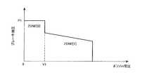
- a brake signal having a potentiometer voltage corresponding to the depression amount is input from the potentiometer 38 to the control unit 7. As shown in FIG. 3, the control unit 7 controls the brake hydraulic pressure according to the potentio voltage corresponding to the operation amount of the brake operation unit 35.
- the brake hydraulic pressure is a hydraulic pressure applied to the brake piston 22 in a direction in which the brake disc 20 moves away from the fixed disc against the urging force of the disc spring, and the brake hydraulic pressure is controlled to control the brake devices 5a and 5b.
- the braking force is controlled. Specifically, when the potentiometer voltage is in a range equal to or higher than V1 (hereinafter referred to as “ZONE [1]”), the brake hydraulic pressure decreases as the potentiometer voltage increases. As a result, the force against the urging force of the disc spring is reduced, and the pressure contact force between the brake disk 20 and the fixed plate 21 is increased. As a result, the braking force is increased.
- the brake hydraulic pressure is held at P1.
- the state where the brake disk 20 is separated from the fixed plate 21 against the biasing force of the disc spring is maintained. That is, play is provided in the brake pedal so that the brake does not enter the braking state when the amount of depression of the brake pedal is small.
- the work vehicle 1 includes a work machine such as a blade, a hydraulic cylinder for driving the work machine, a hydraulic pump for the work machine that supplies pressure oil to the hydraulic cylinder, and the like. And various work by a working machine can be performed by operating the working machine operation part which is not illustrated.
- the control unit 7 is composed of an arithmetic processing unit such as a microcomputer and a numerical arithmetic processor, a memory, and the like.
- the control unit 7 controls the engine 2, the power transmission mechanism 3 and the like based on operation signals from the operation units 32-35, detection signals from various sensors including the engine speed sensor 41, and the like.
- the control unit 7 includes a braking timer 71, a release timer 72, and a storage unit 73.
- the braking timer 71 counts a braking time that is an elapsed time from the start of braking of the brake devices 5a and 5b.
- the release timer 72 counts a braking time that is an elapsed time from the start of braking of the brake devices 5a and 5b.
- the storage unit 73 stores a delay time map.
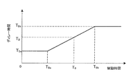
- the delay time map is a map showing a correspondence relationship between the braking time and the delay time, and is obtained in advance by experiments or simulations and stored in the storage unit 73. As shown in FIG.
- the delay time TD is constant at Tda.
- the delay time TD increases from TDi to TDb as the braking time TB increases.
- the delay time TD is constant at TDb.
- the control unit 7 controls the amount of lubricating oil supplied to the brake devices 5a and 5b by controlling the lubricating oil supply unit 6 using the timer function and the delay time map stored in the storage unit 73. .
- the control unit 7 When the brake devices 5a and 5b are in the open state, the control unit 7 turns on the brake demand valve 42. That is, the pilot control valve 44 is excited and the flow rate switching valve 43 is in the second state. Thus, the lubricating oil is supplied to the brake devices 5a and 5b with the second supply amount with a small flow rate.
- the control unit 7 turns off the brake demand valve 42. That is, the pilot control valve 44 is de-energized and the flow rate switching valve 43 is in the first state. Thus, the lubricating oil is supplied to the brake devices 5a and 5b with the first supply amount having a large flow rate.
- the control unit 7 has reached the delay time counted by the release timer 72 from the start of the release of the brake devices 5a and 5b.
- the amount of lubricating oil is reduced from the first supply amount to the second supply amount.
- the delay time TD corresponding to the braking time TB counted by the braking timer 71 is acquired using the delay time map shown in FIG.
- control unit 7 stores the previous braking time in the storage unit 73, and corrects the current braking time by the previous braking time when the release time is shorter than the delay time. Then, the delay time is obtained using the corrected braking time. However, when the opening time exceeds the delay time, the control unit 7 sets the previous braking time value stored in the storage unit 73 to zero. That is, the delay time is obtained using only the current braking time without considering the previous braking time.
- step S1 it is determined that the brake signal is not ZONE [1], and the process proceeds to step S2.
- step S2 the count value Timer_Brk_On of the braking timer 71 is set to zero. Further, the release timer 72 is counted, and the count value Timer_Brk_Off is set as the value of the release time TBoff. However, the count value Timer_Brk_Off remains the maximum value 0 ⁇ FFFF which is the initial value and does not change. Also, the count value Timer_Brk_On of the braking timer 71 remains the initial value zero.
- step S3 it is determined whether or not the brake signal at the previous determination is ZONE [1].
- the previous brake signal is not ZONE [1]
- the process proceeds to step S5.
- step S5 it is determined whether or not the opening time TBoff is longer than the delay time TD.
- the delay time TD is the initial value zero and the release time TBoff is the maximum value 0 ⁇ FFFF, it is determined that the release time TBoff is equal to or greater than the delay time TD, and the process proceeds to step S6.
- step S6 the brake demand valve 42 is turned on.
- the lubricating oil is supplied to the brake devices 5a and 5b with the second supply amount with a small flow rate. That is, when the brake devices 5a and 5b are in an open state, the second supply amount of lubricating oil is supplied to the brake devices 5a and 5b.
- steps S1, S2, S3, S5 and S6 are repeated until time t1 is reached.
- step S1 the brake devices 5a and 5b are switched to the braking state. For this reason, it is determined in step S1 that the brake signal is ZONE [1], and the process proceeds to step S7.
- step S7 the braking timer 71 is counted, and the count value Timer_Brk_On is set as the current braking time TB_curr. That is, the elapsed time from the time t1 is set as the current braking time TB_curr.
- step S8 it is determined whether or not the brake signal at the previous determination is ZONE [0]. Here, it is determined that the brake signal at the previous determination is ZONE [0], and the process proceeds to step S9.
- step S9 the braking time TB stored in the storage unit 73 is set as the previous braking time TB_pre.
- the previous braking time TB_pre is set to zero.
- step S10 it is determined whether or not the opening time TBoff is longer than the delay time TD.
- the delay time TD remains at the initial value zero, and the release time TBoff is the maximum value 0 ⁇ FFFF. For this reason, it is determined that the release time TBoff is longer than the delay time TD, and the process proceeds to step S11.
- step S11 the previous braking time TB_pre is set to zero.
- step S12 the sum of the current braking time TB_curr and the previous braking time TB_pre is set as the braking time TB.
- the current braking time TB_curr that is, the elapsed time from the time t1 is set as the braking time TB.
- step S13 the count value Timer_Brk_Off of the release timer 72 is set to zero.
- step S14 the brake demand valve 42 is turned off.
- the lubricating oil is supplied to the brake devices 5a and 5b with the first supply amount having a large flow rate. That is, when the brake devices 5a and 5b are in a braking state, the first supply amount of lubricating oil is supplied to the brake devices 5a and 5b.
- step S8 it is determined that the brake signal at the previous determination is not ZONE [0], and the process proceeds to step S12.
- the time t2 the time ⁇ T1 from the time t1 to the time t2 is set as the braking time TB and stored in the storage unit 73.
- step S1 it is determined that the brake signal is not ZONE [1], and the process proceeds to step S2.
- step S2 the count value Timer_Brk_On of the braking timer 71 is set to zero. Further, the release timer 72 is counted, and the count value Timer_Brk_Off is set as the value of the release time TBoff. Since the count value Timer_Brk_Off is set to zero in step S13 described above, the elapsed time from the time t2 is set as the value of the open time TBoff here.
- step S3 it is determined whether or not the brake signal at the previous determination is ZONE [1]. Here, it is determined that the brake signal at the time of the previous determination is ZONE [1], and the process proceeds to step S4.
- step S4 the delay time TD is calculated from the braking time TB.
- the delay time TD is calculated from the delay time map shown in FIG. 4 and the braking time TB.
- the delay time TD corresponding to the time ⁇ T1 is set in the delay time map.
- step S5 it is determined whether or not the opening time TBoff is longer than the delay time TD.
- the process proceeds to step S14, and the brake demand valve 42 is kept off. For this reason, the amount of lubricating oil to the brake devices 5a and 5b is maintained at the first supply amount.
- step S3 it is determined that the brake signal at the previous determination is not ZONE [1], and the process proceeds to step 5.
- step S5 When the time t3 is reached, it is determined in step S5 that the opening time TBoff is equal to or greater than the delay time TD, and the process proceeds to step S6.
- step S6 the brake demand valve 42 is turned on. Thereby, the amount of lubricating oil to the brake devices 5a and 5b is reduced from the first supply amount to the second supply amount. Then, returning to step S1, steps S1, S2, S3, S5, and S6 are repeated until time t4 is reached. Thereby, the amount of lubricating oil to the brake devices 5a and 5b is maintained at the second supply amount.
- step S9 the brake devices 5a and 5b are switched to the braking state.
- the process proceeds to step S9 through steps S1, S7, and S8.
- step S9 the braking time TB stored in the storage unit 73 is set as the previous braking time TB_pre.
- the time ⁇ T1 from time t1 to time t2 is stored in the storage unit 73 as the braking time TB.
- the previous braking time TB_pre is set to the time ⁇ T1.
- step S10 it is determined whether or not the opening time TBoff is longer than the delay time TD.
- the process proceeds to step S11.
- step S11 the previous braking time TB_pre is reset from time ⁇ T1 to zero.
- step S12 the sum of the current braking time TB_curr and the previous braking time TB_pre is set as the braking time TB.
- the previous braking time TB_pre is zero
- the current braking time TB_curr that is, the elapsed time from the time t4 is set as the braking time TB.
- step S13 the count value Timer_Brk_Off of the release timer 72 is set to zero.
- step S14 the brake demand valve 42 is turned off. Thereby, the amount of lubricating oil to the brake devices 5a and 5b is increased from the second supply amount to the first supply amount.
- step S8 it is determined that the brake signal at the previous determination is not ZONE [0], and the process proceeds to step S12.
- time t5 time ⁇ T2 from time t4 to time t5 is set as the braking time TB.
- step S4 the delay time TD corresponding to the time ⁇ T2 is calculated in step S4 in the same manner as the above flow, and the brake demand at the time t6 when the delay time TD corresponding to the time ⁇ T2 has elapsed from the time t5.
- Valve 42 is switched on.
- the brake devices 5a and 5b are switched to the braking state after the delay time TD has elapsed from the time t2 (see time t4).
- processing when the brake devices 5a and 5b are switched to the braking state before the delay time TD elapses from the time t2 will be described.
- the processing up to time t2 is the same as described above. Thereby, the time ⁇ T1 from the time t1 to the time t2 is stored in the storage unit 73 as the braking time TB. Further, steps S1, S2, S3, S5, and S14 are repeated until the time ta is reached from the time t2, and the brake demand valve 42 is kept off. For this reason, the amount of lubricating oil to the brake devices 5a and 5b is maintained at the first supply amount.
- step S1 When the brake devices 5a and 5b are switched from the released state to the braked state at time ta before the delay time TD (see “TD1” in FIG. 7) corresponding to time ⁇ T1 elapses from time t2, step S1. The process proceeds to step S9 through S7 and S8.
- step S9 the braking time TB stored in the storage unit 73 is set as the previous braking time TB_pre.
- the time ⁇ T1 from time t1 to time t2 is stored in the storage unit 73 as the braking time TB.
- the previous braking time TB_pre is set to the time ⁇ T1.
- step S10 it is determined whether or not the opening time TBoff is longer than the delay time TD.
- the release time TBoff is the time from the time t2 to the time ta, and is not equal to or greater than the delay time TD, so the process proceeds to step S12.
- step S12 the sum of the current braking time TB_curr and the previous braking time TB_pre is set as the braking time TB.
- ⁇ T1 which is the previous braking time TB_pre and the elapsed time from the time ta which is the current braking time TB_curr are set as the braking time TB.
- step S13 the count value Timer_Brk_Off of the release timer 72 is set to zero.
- step S14 the brake demand valve 42 is kept off. Thereby, the amount of lubricating oil to the brake devices 5a and 5b is maintained at the first supply amount.
- steps S1, S7, S8, S12, S13 and S14 are repeated until time tb.
- the time tb is reached, the sum of the time ⁇ T1 from the time t1 to the time t2 and the time ⁇ T3 from the time ta to the time tb is set as the braking time TB.
- step S4 when the brake devices 5a and 5b are switched from the braking state to the released state at time tb, the process proceeds to step S4 through steps S1, S2, and S3.
- step S4 the delay time TD is calculated from the braking time TB.
- the delay time (see “TD2” in FIG. 7) corresponding to the sum of the time ⁇ T1 and the time ⁇ T3 is set in the delay time map. Is done.
- step S5 it is determined whether or not the opening time TBoff is longer than the delay time TD.
- the process proceeds to step S14, and the brake demand valve 42 is kept off. For this reason, the amount of lubricating oil to the brake devices 5a and 5b is maintained at the first supply amount.
- steps S2, S3, S5, and S14 are repeated until time tc is reached.
- step S5 When the time tc is reached, it is determined in step S5 that the release time TBoff is equal to or greater than the delay time TD, and the process proceeds to step S6.
- step S6 the brake demand valve 42 is switched on. Thereby, the amount of lubricating oil to the brake devices 5a and 5b is reduced from the first supply amount to the second supply amount.
- the lubricating oil amount is not immediately reduced to the second supply amount, but the delay time has elapsed. Sometimes reduced to a second supply.
- the delay time is acquired from the delay time map stored in the storage unit 73 and the actually counted braking time. For this reason, the delay time suitable for the amount of heat generated in the brake devices 5a and 5b can be set. Thereby, loss of driving force in the brake devices 5a and 5b can be suppressed, and occurrence of overheating can be suppressed.
- the delay time when the brake devices 5a and 5b are switched to the released state thereafter is the current braking time. It is calculated from a value obtained by adding the time and the previous braking time. As a result, the brake devices 5a and 5b that have not been sufficiently cooled at the time of the previous opening and the heat remains can be sufficiently cooled at the time of the current opening.
- the delay time when the brake devices 5a and 5b are subsequently switched to the released state does not include the previous braking time. Calculated from time only. For this reason, it is possible to prevent the delay time from being set unnecessarily long, and it is possible to suppress loss of driving force in the brake devices 5a and 5b.
- the second supply amount is a small supply amount, but the second supply amount may be zero.
- the first supply amount is the total amount discharged from the hydraulic pump 30, but may be an amount smaller than the total amount.
- the demand time is used as the reference time when the value of the previous braking time stored in the storage unit 73 is set to 0.
- another reference time may be used.
- a predetermined constant or a value obtained by multiplying the demand time by a predetermined constant may be used.
- the flow rate switching valve 43 may be controlled steplessly or in three or more stages by proportional control.
- the brake demand valve 42 is switched steplessly between a high state and a low state.
- the High state corresponds to the above-described OFF state of the brake demand valve 42, and is a state in which, for example, the amount of lubricating oil is set to the maximum flow rate.
- the Low state corresponds to the on state of the brake demand valve 42 described above, and is a state in which, for example, the amount of lubricating oil is set to 50% of the maximum flow rate.
- the brake demand valve 42 is gradually changed from the high state to the low state. Specifically, as the current value of the control signal to the pilot control valve 44 is gradually increased, the opening degree of the flow rate switching valve 43 gradually decreases. Thereby, after the time tc, the amount of lubricating oil to the brake devices 5a and 5b is gradually reduced from the first supply amount to the second supply amount.
- the present invention is effective as a work vehicle and a work vehicle control method because it has the effect of suppressing the loss of driving force in the brake device and suppressing the occurrence of overheating.
Landscapes
- Engineering & Computer Science (AREA)
- Mechanical Engineering (AREA)
- General Engineering & Computer Science (AREA)
- Transportation (AREA)
- Braking Arrangements (AREA)
- General Details Of Gearings (AREA)
Abstract
Description
本発明の一実施形態に係る潤滑装置を備えた作業車両1の概略システム構成図を図1に示す。この作業車両1は、例えばブルドーザであり、エンジン2、動力伝達機構3、一対の走行装置4a,4b、潤滑油供給部6、各種の操作部32-35、制御部7などを備えている。これらの構成部品のうち潤滑油供給部6および制御部7が、ブレーキ装置5a,5bに冷却用の潤滑油を供給する潤滑装置を構成している。なお、各種の操作部32-35の詳細については後述する。
以下、制御部7が行うブレーキ装置5a,5bへの潤滑油量の制御について、図5のフローチャートおよび図6、図7のタイミングチャートに基づいて詳細に説明する。図5のフローチャートで用いられるパラメータTimer_Brk_On、TB、TD、TB_pre、TB_currの初期値はゼロに設定されている。また、パラメータTimer_Brk_Off、TBoffの初期値は、最大値(0×FFFF)に設定されている。エンジン2が始動されたときには、各パラメータは初期値とされる。なお、エンジン2の始動時ではなく、図示せぬ走行ロックレバーが解除されたとき、すなわち走行可能な状態となったときに各パラメータを初期値とするようにしても良い。
このブレーキ装置5a,5bの潤滑装置では、ブレーキ装置5a,5bが制動状態から開放状態に切り換えられたときに直ちに潤滑油量が第2供給量に低減されるのではなく、ディレー時間が経過したときに第2供給量に低減される。そして、このディレー時間は、記憶部73に記憶されたディレー時間マップと、実際にカウントされた制動時間とから取得される。このため、ブレーキ装置5a,5bにおいて発生した熱量に適したディレー時間を設定することができる。これにより、ブレーキ装置5a,5bにおける駆動力のロスを抑制することができると共に、オーバーヒートの発生を抑えることができる。
(a)上記の実施形態では制動時間とディレー時間との対応関係を示すマップが用いられているが、テーブルなどの他の算出手段が用いられてもよい。また、ディレー時間マップは上記のような形状に限らず、異なる形状のものが用いられてもよい。
流量切換弁43は比例制御によって無段階あるいは3以上の多段階に制御されてもよい。この場合、図8(b)に示すように、ブレーキディマンド弁42は、High状態とLow状態との間で無段階に切り換えられる。High状態とは、上記のブレーキディマンド弁42のオフ状態に相当し、例えば、潤滑油量が最大流量とされる状態である。Low状態は、上記のブレーキディマンド弁42のオン状態に相当し、例えば、潤滑油量が最大流量の50%にされる状態である。
上記の潤滑油の供給量の制御は、ステアリング操作部34の操作によってブレーキ装置5a,5bの制動と開放とが切り換えられる場合にも適用することができる。また、この場合、例えば、旋回操作時に片側のブレーキ装置だけ制動状態となっていても、左右両方のブレーキ装置5a,5bの潤滑油量を増加させてもよい。また、旋回操作時に一方のブレーキ装置だけが制動状態である場合は、開放状態である他方のブレーキ装置に対しては潤滑油量を増加させないようにしてもよい。
6 潤滑油供給部
7 制御部7
71 制動タイマー
72 開放タイマー
73 記憶部
TB 制動時間
TBoff 開放時間
TD ディレー時間
TB_pre 前回の制動時間
TB_curr 今回の制動時間
Claims (4)
- ブレーキ装置に冷却用の潤滑油を供給する潤滑装置であって、
前記潤滑油を前記ブレーキ装置に供給する潤滑油供給部と、
前記ブレーキ装置の制動開始からの経過時間である制動時間をカウントする制動タイマーと、前記ブレーキ装置の開放開始からの経過時間である開放時間をカウントする開放タイマーと、前記制動時間とディレー時間との対応関係を記憶している記憶部と、を有し、前記ブレーキ装置が制動状態である場合には所定の第1供給量の潤滑油を前記ブレーキ装置に供給するように前記潤滑油供給部を制御し、前記ブレーキ装置が制動状態から開放状態に切り換えられたときに、前記制動タイマーによってカウントされた制動時間に対応するディレー時間を前記記憶部に記憶された対応関係から取得し、前記開放タイマーによってカウントされた開放時間が、取得した前記ディレー時間に達したときに、潤滑油量を前記第1供給量から前記第1供給量より少ない第2供給量に切り換える制御部と、
を備えるブレーキ装置の潤滑装置。 - 前記制御部は、前記制動タイマーによってカウントされた前回の制動時間を前記記憶部に記憶させ、前記記憶部に記憶された前回の制動時間によって、前記制動タイマーによってカウントされた今回の前記制動時間を補正する、
請求項1に記載のブレーキ装置の潤滑装置。 - 前記制御部は、前記開放タイマーによってカウントされた開放時間が予め定められた基準時間を越えた場合には、前記記憶部に記憶された前回の制動時間の値を0にする、
請求項2に記載のブレーキ装置の潤滑装置。 - ブレーキ装置に冷却用の潤滑油を供給する潤滑装置の制御方法であって、
前記ブレーキ装置の制動開始からの経過時間である制動時間を制動タイマーによってカウントするステップと、
前記ブレーキ装置の開放開始からの経過時間である開放時間を開放タイマーによってカウントするステップと、
前記ブレーキ装置が制動状態である場合に、所定の第1供給量の潤滑油を前記ブレーキ装置に供給するステップと、
前記ブレーキ装置が制動状態から開放状態に切り換えられたときに、前記制動タイマーによってカウントされた制動時間に対応するディレー時間を、記憶部に記憶された前記制動時間とディレー時間との対応関係から取得するステップと、
前記開放タイマーによってカウントされた開放時間が、取得した前記ディレー時間に達したときに、潤滑油量を前記第1供給量から前記第1供給量より少ない第2供給量に切り換えるステップと、
を備えるブレーキ装置の潤滑装置の制御方法。
Priority Applications (3)
| Application Number | Priority Date | Filing Date | Title |
|---|---|---|---|
| CN2009801504686A CN102256840B (zh) | 2008-12-16 | 2009-12-08 | 制动装置的润滑装置及其控制方法 |
| DE112009004351.8T DE112009004351B4 (de) | 2008-12-16 | 2009-12-08 | Bremsschmiervorrichtung und Verfahren zu deren Steuerung |
| US13/127,339 US8430216B2 (en) | 2008-12-16 | 2009-12-08 | Brake device lubrication device and method for controlling same |
Applications Claiming Priority (2)
| Application Number | Priority Date | Filing Date | Title |
|---|---|---|---|
| JP2008-319452 | 2008-12-16 | ||
| JP2008319452A JP5227772B2 (ja) | 2008-12-16 | 2008-12-16 | ブレーキ装置の潤滑装置およびその制御方法 |
Publications (1)
| Publication Number | Publication Date |
|---|---|
| WO2010071047A1 true WO2010071047A1 (ja) | 2010-06-24 |
Family
ID=42268718
Family Applications (1)
| Application Number | Title | Priority Date | Filing Date |
|---|---|---|---|
| PCT/JP2009/070508 Ceased WO2010071047A1 (ja) | 2008-12-16 | 2009-12-08 | ブレーキ装置の潤滑装置およびその制御方法 |
Country Status (5)
| Country | Link |
|---|---|
| US (1) | US8430216B2 (ja) |
| JP (1) | JP5227772B2 (ja) |
| CN (1) | CN102256840B (ja) |
| DE (1) | DE112009004351B4 (ja) |
| WO (1) | WO2010071047A1 (ja) |
Families Citing this family (7)
| Publication number | Priority date | Publication date | Assignee | Title |
|---|---|---|---|---|
| RU2600423C2 (ru) * | 2012-02-17 | 2016-10-20 | Инвенцио Аг | Тормозная система лифта и способ торможения кабины лифта |
| JP6584271B2 (ja) | 2015-10-09 | 2019-10-02 | 株式会社小松製作所 | ブルドーザ |
| FR3054010B1 (fr) * | 2016-07-13 | 2018-08-17 | Poclain Hydraulics Ind | Systeme de freinage ameliore pour machine hydraulique |
| CN108561466B (zh) * | 2018-05-07 | 2024-01-26 | 宁夏天地奔牛实业集团有限公司 | 适用于煤矿井下刮板输送机动力部离合制动紧链装置 |
| DE102020205867A1 (de) | 2020-05-11 | 2021-11-11 | Zf Friedrichshafen Ag | Verfahren zur Kühlung einer mechanischen Reibungsbremse eines hydrostatisch-mechanischen Leistungsverzweigungsgetriebes, hydrostatisch-mechanisches Leistungsverzweigungsgetriebe und Arbeitsmaschine |
| CN111775626A (zh) * | 2020-06-23 | 2020-10-16 | 西安法士特汽车传动有限公司 | 一种大马力hmcvt拖拉机后桥制动的润滑控制方法 |
| CN114462166B (zh) * | 2022-02-17 | 2024-03-15 | 成都飞机工业(集团)有限责任公司 | 一种电控刹车阀设计方法、装置、设备及介质 |
Citations (5)
| Publication number | Priority date | Publication date | Assignee | Title |
|---|---|---|---|---|
| JPH0487864A (ja) * | 1990-07-31 | 1992-03-19 | Hino Motors Ltd | 流体式リターダの冷却装置 |
| JPH0471829U (ja) * | 1990-10-31 | 1992-06-25 | ||
| JPH07501128A (ja) * | 1991-11-22 | 1995-02-02 | クノルーブレムゼ アクチェンゲゼルシャフト | 空冷摩擦ブレーキ及び過給内燃機関を有する自動車 |
| JP2003172439A (ja) * | 2001-12-10 | 2003-06-20 | Toyota Motor Corp | 潤滑装置 |
| JP2006341636A (ja) * | 2005-06-07 | 2006-12-21 | Toyota Motor Corp | 車両用可動スパッツ制御装置 |
Family Cites Families (9)
| Publication number | Priority date | Publication date | Assignee | Title |
|---|---|---|---|---|
| GB1541523A (en) * | 1976-09-08 | 1979-03-07 | Caterpillar Tractor Co | Drive assembly having clutch and brake lubricating system |
| US4540078A (en) | 1983-10-27 | 1985-09-10 | Deere & Company | Clutch lube control |
| EP0801253A3 (en) * | 1987-05-22 | 1998-03-04 | Kabushiki Kaisha Komatsu Seisakusho | Apparatus for controlling lock-up clutch |
| JP3877178B2 (ja) | 1992-07-17 | 2007-02-07 | Tdk株式会社 | 真空蒸着装置 |
| ITMI20040197A1 (it) * | 2004-02-09 | 2004-05-09 | Astra Veicoli Ind S P A | Procedimento e circuito per la regolazione della portata di olio idraulico di raffreddamwento freni di un veicolo |
| DE102006011801A1 (de) * | 2006-03-15 | 2007-09-20 | Zf Friedrichshafen Ag | Verfahren zur Kühlung eines Reibschaltelementes eines Getriebes |
| DE102006031787A1 (de) * | 2006-07-10 | 2007-04-12 | Zf Friedrichshafen Ag | Lamellenbremse in einem Automatgetriebe mit steuerbarer Kühlölversorgung und Verfahren zum Betreiben derselben |
| WO2008106927A1 (de) * | 2007-03-07 | 2008-09-12 | Luk Lamellen Und Kupplungsbau Beteiligungs Kg | Hydraulikanordnung zur steuerung eines doppelkupplungsgetriebes eines kraftfahrzeuges |
| JP4696105B2 (ja) * | 2007-11-30 | 2011-06-08 | 本田技研工業株式会社 | 自動二輪車のクラッチ制御装置 |
-
2008
- 2008-12-16 JP JP2008319452A patent/JP5227772B2/ja not_active Expired - Fee Related
-
2009
- 2009-12-08 DE DE112009004351.8T patent/DE112009004351B4/de not_active Expired - Fee Related
- 2009-12-08 US US13/127,339 patent/US8430216B2/en active Active
- 2009-12-08 WO PCT/JP2009/070508 patent/WO2010071047A1/ja not_active Ceased
- 2009-12-08 CN CN2009801504686A patent/CN102256840B/zh not_active Expired - Fee Related
Patent Citations (5)
| Publication number | Priority date | Publication date | Assignee | Title |
|---|---|---|---|---|
| JPH0487864A (ja) * | 1990-07-31 | 1992-03-19 | Hino Motors Ltd | 流体式リターダの冷却装置 |
| JPH0471829U (ja) * | 1990-10-31 | 1992-06-25 | ||
| JPH07501128A (ja) * | 1991-11-22 | 1995-02-02 | クノルーブレムゼ アクチェンゲゼルシャフト | 空冷摩擦ブレーキ及び過給内燃機関を有する自動車 |
| JP2003172439A (ja) * | 2001-12-10 | 2003-06-20 | Toyota Motor Corp | 潤滑装置 |
| JP2006341636A (ja) * | 2005-06-07 | 2006-12-21 | Toyota Motor Corp | 車両用可動スパッツ制御装置 |
Also Published As
| Publication number | Publication date |
|---|---|
| CN102256840A (zh) | 2011-11-23 |
| JP5227772B2 (ja) | 2013-07-03 |
| JP2010143259A (ja) | 2010-07-01 |
| CN102256840B (zh) | 2013-12-25 |
| DE112009004351T5 (de) | 2012-06-28 |
| DE112009004351B4 (de) | 2014-09-25 |
| US8430216B2 (en) | 2013-04-30 |
| US20110214952A1 (en) | 2011-09-08 |
Similar Documents
| Publication | Publication Date | Title |
|---|---|---|
| JP5227772B2 (ja) | ブレーキ装置の潤滑装置およびその制御方法 | |
| JP5389248B2 (ja) | 作業車両および作業車両の制御方法 | |
| JP5609993B2 (ja) | ハイブリッド車両の制御装置 | |
| CN108025657B (zh) | 电动车辆的控制装置及控制方法 | |
| SE534707C2 (sv) | Regleranordning för en kylfläkt avsedd för ett fordon | |
| JP2009196393A (ja) | 作業車両 | |
| JP2010229910A (ja) | 作業車両における駆動力制御装置 | |
| KR102837227B1 (ko) | 차량의 파워트레인에 설치된 하이브리드 분리 클러치의 마찰값을 능동적으로 변경하는 방법 | |
| JP4670865B2 (ja) | 産業車両における作業機用ポンプの駆動装置 | |
| JP7070717B2 (ja) | 車両用駆動装置 | |
| JP6175586B2 (ja) | 駆動力配分装置の油圧制御装置 | |
| JP2009052638A (ja) | 自動変速機における作動油供給装置 | |
| US7641589B2 (en) | Motor vehicle equipped with a service brake and with a parking brake | |
| JP7131419B2 (ja) | 車両用駆動装置の油圧制御装置及びハイブリッド車両 | |
| JP6190985B2 (ja) | 駆動力配分装置の油圧制御装置 | |
| JP4145993B2 (ja) | 車両の動力伝達装置 | |
| JP2013249892A (ja) | 産業車両の制御装置 | |
| WO2020066750A1 (ja) | 作業車両 | |
| JP6013757B2 (ja) | 動力伝達装置及び車両 | |
| JP2014169720A (ja) | 車両の制御装置 | |
| JP2599827B2 (ja) | 作業車の走行変速構造 | |
| AU2007322928A1 (en) | Power transmission device | |
| JPH0659799B2 (ja) | 作業車の走行用油圧クラッチ装置 | |
| JP2018034700A (ja) | 四輪駆動車両のトルク制御装置 | |
| JP2016223566A (ja) | 車両の油圧制御装置 |
Legal Events
| Date | Code | Title | Description |
|---|---|---|---|
| WWE | Wipo information: entry into national phase |
Ref document number: 200980150468.6 Country of ref document: CN |
|
| 121 | Ep: the epo has been informed by wipo that ep was designated in this application |
Ref document number: 09833351 Country of ref document: EP Kind code of ref document: A1 |
|
| WWE | Wipo information: entry into national phase |
Ref document number: 13127339 Country of ref document: US |
|
| WWE | Wipo information: entry into national phase |
Ref document number: 1120090043518 Country of ref document: DE Ref document number: 112009004351 Country of ref document: DE |
|
| 122 | Ep: pct application non-entry in european phase |
Ref document number: 09833351 Country of ref document: EP Kind code of ref document: A1 |