WO2010070969A1 - ガラス板梱包用パレット - Google Patents
ガラス板梱包用パレット Download PDFInfo
- Publication number
- WO2010070969A1 WO2010070969A1 PCT/JP2009/067395 JP2009067395W WO2010070969A1 WO 2010070969 A1 WO2010070969 A1 WO 2010070969A1 JP 2009067395 W JP2009067395 W JP 2009067395W WO 2010070969 A1 WO2010070969 A1 WO 2010070969A1
- Authority
- WO
- WIPO (PCT)
- Prior art keywords
- glass plate
- packing
- pallet
- glass
- base portion
- Prior art date
- Legal status (The legal status is an assumption and is not a legal conclusion. Google has not performed a legal analysis and makes no representation as to the accuracy of the status listed.)
- Ceased
Links
Images





Classifications
-
- B—PERFORMING OPERATIONS; TRANSPORTING
- B65—CONVEYING; PACKING; STORING; HANDLING THIN OR FILAMENTARY MATERIAL
- B65D—CONTAINERS FOR STORAGE OR TRANSPORT OF ARTICLES OR MATERIALS, e.g. BAGS, BARRELS, BOTTLES, BOXES, CANS, CARTONS, CRATES, DRUMS, JARS, TANKS, HOPPERS, FORWARDING CONTAINERS; ACCESSORIES, CLOSURES, OR FITTINGS THEREFOR; PACKAGING ELEMENTS; PACKAGES
- B65D85/00—Containers, packaging elements or packages, specially adapted for particular articles or materials
- B65D85/30—Containers, packaging elements or packages, specially adapted for particular articles or materials for articles particularly sensitive to damage by shock or pressure
- B65D85/48—Containers, packaging elements or packages, specially adapted for particular articles or materials for articles particularly sensitive to damage by shock or pressure for glass sheets
-
- B—PERFORMING OPERATIONS; TRANSPORTING
- B65—CONVEYING; PACKING; STORING; HANDLING THIN OR FILAMENTARY MATERIAL
- B65D—CONTAINERS FOR STORAGE OR TRANSPORT OF ARTICLES OR MATERIALS, e.g. BAGS, BARRELS, BOTTLES, BOXES, CANS, CARTONS, CRATES, DRUMS, JARS, TANKS, HOPPERS, FORWARDING CONTAINERS; ACCESSORIES, CLOSURES, OR FITTINGS THEREFOR; PACKAGING ELEMENTS; PACKAGES
- B65D19/00—Pallets or like platforms, with or without side walls, for supporting loads to be lifted or lowered
- B65D19/38—Details or accessories
- B65D19/385—Frames, corner posts or pallet converters, e.g. for facilitating stacking of charged pallets
-
- B—PERFORMING OPERATIONS; TRANSPORTING
- B65—CONVEYING; PACKING; STORING; HANDLING THIN OR FILAMENTARY MATERIAL
- B65D—CONTAINERS FOR STORAGE OR TRANSPORT OF ARTICLES OR MATERIALS, e.g. BAGS, BARRELS, BOTTLES, BOXES, CANS, CARTONS, CRATES, DRUMS, JARS, TANKS, HOPPERS, FORWARDING CONTAINERS; ACCESSORIES, CLOSURES, OR FITTINGS THEREFOR; PACKAGING ELEMENTS; PACKAGES
- B65D19/00—Pallets or like platforms, with or without side walls, for supporting loads to be lifted or lowered
- B65D19/38—Details or accessories
- B65D19/44—Elements or devices for locating articles on platforms
Definitions
- the present invention relates to a technique for improving a glass plate packing pallet for packing a glass plate laminate formed by laminating a plurality of glass plates in a flat position.
- FPD glass substrates for flat panel displays
- liquid crystal displays plasma displays
- electroluminescence displays electroluminescence displays
- field emission displays field emission displays
- Patent Document 1 As a packaging form of this type of glass plate, one that is packaged in a state of a glass plate laminate in which a plurality of glass plates are laminated on the base portion of the pallet is known (for example, Patent Document 1). To 4).
- this packing form since the weight of the glass plate is mainly supported by the plane of the glass plate, there is an advantage that it is difficult to concentrate unnecessary stress on the side of the glass plate that is easily damaged. Therefore, it can be said that it is one of the packaging forms that can suitably prevent breakage of the glass plate corresponding to the demands for enlargement and thinning as described above.
- the above-mentioned support columns need to support the upper pallet when stacking a plurality of pallets, they protrude upward from the glass plate laminate. That is, since the column is in a state of protruding upward from the glass support surface that supports the glass plate laminate in the base portion, the column and the glass plate are used when the glass plate laminate is loaded and unloaded. May interfere with the work.
- Patent Document 1 it may be possible to attach the support column to the base part in a detachable manner, but in this case, the removed support column may be lost.
- various types of glass plates are packed and transported on different types of pallets, various pallets are mixed and the possibility of the loss of the columns becomes higher.
- the present invention loses a packaging component that is disposed around a glass plate laminate in a state of protruding upward from the glass plate support surface of the base portion and is used for packing the glass plate laminate. Therefore, it is a technical problem to store the glass plate laminate so as not to obstruct the work of loading and unloading the glass plate laminate.
- the present invention provides a base portion having a glass support surface for supporting the bottom surface of a glass plate laminate in which a plurality of glass plates are laminated in a flat position, and the glass of the base portion.
- a pallet for packing a glass plate which is disposed around the glass plate laminate in a protruding state protruding above the support surface and is used for packing the glass plate laminate, It is characterized in that the base portion is provided with an accommodating portion for accommodating the packaging component in a state where the height is lower than the protruding state.
- the packaging parts can be stored and stored in the storage part provided in the base part. That is, since the packaging parts are stored on the pallet itself, it is possible to prevent a situation where the packaging parts are lost. Moreover, since the height of the packaging component is lower than the protruding state before accommodation in the state where the packaging component is accommodated in the accommodation portion provided in the base portion, the packaging component is used for loading and unloading the glass plate laminate. It becomes difficult to get in the way, and the operation can be smoothly executed.
- the storage portion is configured to store the packing component at a position below the glass support surface of the base portion.
- the housing portion may be provided in an internal space of the base portion.
- the base part of the pallet is usually formed with a space from the viewpoint of weight reduction, if the above configuration is adopted, the internal space can be accommodated as it is for accommodating packaging parts. There is an advantage that it can be used effectively as a part.
- the storage portion is formed by a storage hole provided in the base portion, and the packing component is stored in a state of being inserted into the storage hole.
- the packing part can be accommodated in a stable state because the movable range of the packing part is limited to the inside of the accommodation hole.
- a lid for opening and closing the entrance of the storage hole is provided.
- the storage unit may be configured to store the packing component in a state of being tilted with respect to the base unit.
- the packaging component can be accommodated simply by tilting it against the base, so that the packaging component can be accommodated very easily.
- the packaging component may be connected to a part of the base portion, and the packaging component may be tilted with the coupling portion as a fulcrum. In this case, since the packaging component is always connected to the base part, it is possible to reliably prevent the packaging component from being lost.
- the accommodating portion is configured to accommodate the packing component in a state where the packing component is attracted and held by magnetic force.
- the packaging component is accommodated in a state in which the packaging component is attracted and held by the magnetic force, the accommodated packaging component does not move unnecessarily, and a stable accommodation state can be maintained.
- the packing component may be a column that is erected on the four corners of the base portion and supports the upper glass plate packing pallet when stacking a plurality of glass plate packing pallets, It may be a press plate that stands on the base portion so as to face the side surface of the glass plate laminate and prevents lateral displacement of the glass plate laminate. Further, the packing component is erected on the four corners of the base portion and faces the side surface of the glass plate laminate, and a column that supports the upper glass plate packing pallet when stacking a plurality of glass plate packing pallets. As described above, the presser plate may be configured to stand on the base portion and prevent lateral displacement of the glass plate laminate.
- packing parts such as columns and press plates can be stored without losing them so as not to obstruct the work of loading and unloading the glass plate laminate.
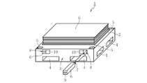
- FIG. 1 is a perspective view schematically showing a glass plate packing pallet according to a first embodiment of the present invention.
- This pallet 1 for glass plate packing is provided with the base part 3 which has the glass support surface 2 which supports the bottom face of the glass plate laminated body G which laminated
- a protective sheet such as a slip sheet or a foamed resin sheet is interposed between the plurality of glass plates included in the glass plate laminate G.
- a cushioning material such as a foamed resin sheet (for example, a polypropylene three-fold foamed resin sheet (trade name: Palonia (registered trademark)) is laid on the glass support surface 2 of the base part 3.
- a foamed resin sheet for example, a polypropylene three-fold foamed resin sheet (trade name: Palonia (registered trademark)
- the base part 3 is configured by combining a plurality of metal beams in a lattice shape, and has a space inside. A part of the internal space of the base part 3 is used as a claw insertion opening 4 for inserting a claw of a forklift. Further, as shown in FIG. 2, support holes 5 are provided in the upper four corners of the base part 3 downward in the vertical direction, and support columns 6, which are one of the packing parts, are provided in each support hole 5. It is erected in the inserted state.
- the column 6 plays a role of supporting the upper pallet 1 when the plurality of pallets 1 are stacked and transported, so that the glass plate laminated body G placed on the glass support surface 2 of the base part 3 is supported. It protrudes upward from the top surface of.
- the fitting convex part 7 is provided in the upper end surface of the support
- pillar 6 which protrudes upwards rather than the uppermost surface of the glass plate laminated body G is used for packing of the glass plate laminated body G in the state which protruded upwards rather than the glass support surface 2 of the base part 3.
- FIG. Therefore, in the state where the support column 6 is always erected on the base 3, the glass plate stack G is unloaded and hindered. Therefore, the column 6 is removed from the support hole 5 of the base 3 at the time of loading and unloading the glass plate laminate G. At this time, the storage location of the support 6 becomes a problem, but in this embodiment, the support 6 is accommodated and stored as follows.
- a housing hole 8 that functions as a housing portion for the support column 6 is opened on the side surface of the base portion 3, and the support column 6 is inserted into the housing hole 8 and stored as shown in FIG. 2. It is like that.
- the accommodation hole 8 for accommodating the support column 6 is not limited to the one provided in the horizontal direction from the side surface of the base part 3, and is provided from the upper part of the base part 3 downward in the vertical direction or downward in the inclined direction. It may be. In this case, it is preferable that the upper part of the accommodated support column 6 does not protrude above the glass plate support surface 2.
- the support column 6 is accommodated inside the accommodation hole 8 of the base part 3, it is accommodated below the glass support surface 2. Therefore, since the support column 6 in the accommodated state does not protrude above the glass support surface 2, it does not interfere with the work of unloading and unloading the glass plate laminate G like the support column 6 before the accommodation, and the operation can be performed. It becomes possible to execute smoothly.
- the lower end surface of the support column 6 is provided with a recess 9 to which an operator's finger or the like can be inserted when the support column 6 accommodated in the accommodation hole 8 is taken out.
- a lid 10 is attached that closes the entrance of the accommodation hole 8 so that it can be opened and closed.
- the lid 10 may be configured to be simply fitted into the entrance of the accommodation hole 8, but in the present embodiment, the lid 10 is fixed to the side surface of the base portion 3 with a hinge or the like and is connected to the base portion 3. It can be opened and closed in the closed state.
- a magnet (not shown) is attached to at least one of the inner surface of the accommodation hole 8 and the side surface of the support column 6 so that the support column 6 is attracted and held inside the accommodation hole 8 by magnetic force.
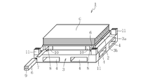
- FIG. 3 is a perspective view showing a glass plate packing pallet according to a second embodiment of the present invention.
- the glass plate packing pallet 1 according to the second embodiment is different from the glass plate packing pallet 1 according to the first embodiment in that the base portion 3 is configured in a step shape. That is, in the pallet 1 according to the present embodiment, the upper stage 3 a of the base part 3 is configured to be smaller than the lower stage 3 b, and the upper surface of the upper stage 3 a constitutes the glass support surface 2.
- the glass support surface 2 of the upper step portion 3a is set to a size that is the same as or slightly larger than the glass plate of the glass plate laminate G.
- support columns 6 are erected at the upper four corners of the lower step portion 3b which is larger than the upper step portion 3a.
- pillar 6 is standingly installed in the state inserted in the support pipe
- pillar 6 is accommodated in the inside of the accommodation hole 8 opened to the side surface of the upper stage part 3a of the base part 3, as shown in FIG.
- the support tube 11 provided in the lower step portion 3b remains in a state of protruding upward from the upper portion of the lower step portion 3b after the support 6 is removed, the support tube 11 is interposed between the lower step portion 3b and the upper step portion 3a.
- the other points such as providing the lid 10 at the entrance of the accommodation hole 8 and attracting and holding the column 6 by magnetic force inside the accommodation hole 8 are the same as those of the pallet 1 according to the first embodiment.
- support holes may be provided in the upper four corners of the lower step portion 3 b downward in the vertical direction, and the columns 6 may be inserted into the support holes.
- FIG. 5 is a perspective view showing a glass plate packing pallet according to a third embodiment of the present invention.
- the glass plate packing pallet 1 according to the third embodiment is different from the glass plate packing pallet 1 according to the second embodiment in the method of housing the support columns 6. That is, in this embodiment, the support column 6 is tiltably attached to the lower step portion 3b of the base unit 3. When the support column 6 is accommodated, as shown in FIG. The unit 3 is tilted along the upper part of the lower step part 3b. In this embodiment, the support column 6 is fixed to the upper portion of the lower step portion 3b of the base portion 3 via a hinge or the like, and falls down while being connected to the lower step portion 3b of the base portion 3. Yes.
- the support column 6 since the support column 6 is always connected to the base portion 3, the loss of the support column 6 can be reliably prevented.
- pillar 6 may come off from the base part 3, In this case, for example, a recessed part was provided in the upper part of the lower step part 3b of the base part 3, and this recessed part was brought down from the standing posture. You may make it accommodate the support
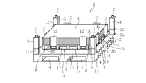
- FIG. 7 is a perspective view showing a glass plate packing pallet according to a fourth embodiment of the present invention.
- the glass plate packing pallet 1 according to the fourth embodiment is different from the glass plate packing pallet 1 according to the second to third embodiments in that the glass plate stack G is added as a packing component in addition to the columns 6.
- the presser plate 12 is provided to prevent lateral displacement.
- the presser plate 12 is provided to face the side surface of the glass plate laminate G placed on the glass support surface 2. In this embodiment, the presser plate 12 is provided at positions corresponding to all four side surfaces of the glass plate laminate G.
- the lower part of the presser plate 12 is attached to the side surface of the upper stage part 3a of the base part 3, and the upper part extends to the side of the glass plate laminate G.
- a cushioning material such as rubber is attached to the surface of the presser plate 12 that faces the side surface of the glass plate laminate G. Since the presser plate 12 protrudes upward from the glass support surface 2, it interferes with the work when the glass plate laminate G is loaded and unloaded like the support 6. For this reason, the presser plate 12 is removed from the side surface of the upper step portion 3a of the base portion 3 when the glass plate laminate G is loaded and unloaded. At this time, the storage location of the presser plate 12 becomes a problem, but in this embodiment, the presser plate 12 is accommodated and stored as follows.
- an accommodation hole 13 for accommodating the presser plate 12 is provided in the base portion 3, and the presser plate 12 is accommodated inside the accommodation hole 13 as shown in FIG. 8. Yes. Furthermore, in this embodiment, a screw for attaching the presser plate 12 to the side surface of the upper step portion 3 a of the base portion 3 is prevented from being removed from the presser plate 12. Is to be housed. In the case of the column 6, the point that the lid 14 for opening and closing the entrance of the accommodation hole 13 that accommodates the presser plate 12 is provided, the point that the presser plate 12 is attracted and held inside the accommodation hole 13 by magnetic force, and the like. It is the same.
- pillar 6 and the press plate 12 was demonstrated as a packaging component, the pallet 1 which consists of the press plate 12 which abbreviate
- the final packing form of the glass plate laminate G will be described by taking the fourth embodiment as an example.
- a plastic bag is included so as to include the presser plate 12 and the glass plate laminate G from the side of the upper step portion 3a.
- a plastic bag is put on the outside so as to include the support column 6 from the side of the lower step portion 3b.
Landscapes
- Engineering & Computer Science (AREA)
- Mechanical Engineering (AREA)
- Packaging Frangible Articles (AREA)
- Pallets (AREA)
Abstract
基台部のガラス板支持面よりも上方に突出した状態でガラス板積層体の周囲に配置されてガラス板積層体の梱包に使用する梱包部品を、紛失することなく、ガラス板積層体の積降し作業の邪魔にならないように保管する。 複数枚のガラス板を平置きで積層したガラス板積層体Gの底面をガラス支持面2で支持する基台部3と、基台部3のガラス支持面2よりも上方に突出した突出状態でガラス板積層体Gの周囲に配置され、ガラス板積層体Gの梱包に使用する支柱6とを備えたガラス板梱包用パレット1であって、支柱6の高さが突出状態よりも低くなるように支柱6を収容する収容孔6を基台部3に設けた。
Description
本発明は、複数枚のガラス板を平置きで積層してなるガラス板積層体を梱包するためのガラス板梱包用パレットの改良技術に関する。
周知のように、液晶ディスプレイ、プラズマディスプレイ、エレクトロルミネッセンスディスプレイ、フィールドエミッションディスプレイなどのフラットパネルディスプレイ(以下、FPDという)用ガラス基板などの各種ガラス板は、近年、大型化及び薄肉化が要請されているのが実情である。そのため、ガラス板に破損が生じ易くなっており、輸送する際のガラス板の梱包形態が極めて重要となっている。
この種のガラス板の梱包形態としては、パレットの基台部に複数枚のガラス板を平置きで積層したガラス板積層体の状態で梱包するものが公知となっている(例えば、特許文献1~4参照)。この梱包形態では、ガラス板の重量は主にガラス板の平面で支持されるので、破損を来たし易いガラス板の辺に無用な応力が集中し難くなるという利点がある。そのため、上述のような大型化と薄肉化の要請に対応したガラス板の破損を好適に防止し得る梱包形態の一つであると言える。
そして、当該梱包形態では、トラックの荷台などに積み込んで輸送する際に、上方の空間が無駄にならないように、ガラス板積層体が梱包された複数のパレットが、上下方向に積み重ねられる場合が多い。そのため、この場合には、当該梱包形態に使用されるパレットの基台部の四隅に支柱が立設され、その支柱により上方のパレットを支持するようになっている。
ところで、上述の支柱は、複数のパレットを積み重ねるときに、上方のパレットを支持する必要があることから、ガラス板積層体よりも上方に突出している。すなわち、支柱は、基台部におけるガラス板積層体を支持するガラス支持面よりも上方に突出した状態となっているため、ガラス板積層体の積降し作業を行う際に支柱とガラス板とが接触するおそれがあり、作業の邪魔になる。
そこで、例えば特許文献1に開示されているように、支柱を基台部に対して着脱自在に取り付けることも考えられるが、この場合には取り外した支柱を紛失してしまう可能性がある。特に、多品種のガラス板を異なる種類のパレットに梱包して輸送する場合には、種々のパレットが混在して支柱の紛失の可能性はより高くなる。
なお、以上では、梱包部品の一つである支柱を例にとって説明したが、基台部のガラス板支持面よりも上方に突出した状態でガラス板積層体の周囲に配置され、ガラス板積層体の梱包に使用する梱包部品であれば、同様の問題が生じ得る。すなわち、このような梱包部品は、支柱と同様に、ガラス板積層体の積降し作業の邪魔になり、取外し可能とすれば紛失の可能性も生じる。
本発明は、上記実情に鑑み、基台部のガラス板支持面よりも上方に突出した状態でガラス板積層体の周囲に配置されてガラス板積層体の梱包に使用する梱包部品を、紛失することなく、ガラス板積層体の積降し作業の邪魔にならないように保管することを技術的課題とする。
上記課題を解決するために創案された本発明は、複数枚のガラス板を平置きで積層したガラス板積層体の底面を支持するガラス支持面を有する基台部と、該基台部のガラス支持面よりも上方に突出した突出状態で前記ガラス板積層体の周囲に配置され、前記ガラス板積層体の梱包に使用される梱包部品とを備えたガラス板梱包用パレットにおいて、前記梱包部品の高さを前記突出状態よりも低くした状態で前記梱包部品を収容する収容部を前記基台部に設けたことに特徴づけられる。
このような構成によれば、基台部に設けられた収容部に梱包部品を収容して保管することができる。すなわち、梱包部品は、パレット自体に保管されることになるので、梱包部品が紛失するという事態を防止することができる。しかも、基台部に設けられた収容部に梱包部品を収容した状態で、梱包部品の高さは収容前の突出状態よりも低くなるので、梱包部品がガラス板積層体の積降し作業の邪魔になり難くなり、当該作業を円滑に実行することが可能となる。
上記の構成において、前記収容部が、前記梱包部品を前記基台部のガラス支持面よりも下方位置で収容するように構成されていることが好ましい。
このようにすれば、基台部のガラス支持面よりも上方に、収容された梱包部品が突出しないので、ガラス板積層体の積降し作業をより一層円滑に行うことが可能となる。
上記の構成において、前記収容部が、前記基台部の内部空間に設けられていてもよい。
すなわち、パレットの基台部は、軽量化の観点からも、内部に空間が形成されているのが通例であることから、上記のような構成にすれば、当該内部空間をそのまま梱包部品の収容部として有効に利用できるという利点がある。
上記の構成において、前記収容部が、前記基台部に設けられた収容孔により構成されており、前記梱包部品が前記収容孔の内部に挿入された状態で収容されることが好ましい。
このようにすれば、梱包部品は、梱包部品の移動可能範囲が収容孔内に限られるので、梱包部品を安定した状態で収容することができる。
上記の構成において、前記収納孔の入口を開閉する蓋が設けられていることが好ましい。
このようにすれば、収納孔の内部に梱包部品を挿入して収容した後に蓋を閉めることで、梱包部品が収容孔の入口から外部に脱落するという事態を防止することができる。
上記の構成において、前記収容部が、前記梱包部品を前記基台部に対して倒した状態で収容するように構成されていてもよい。
このようにすれば、梱包部品を単に基台部に対して倒すだけで収容することができるので、梱包部品の収容作業が極めて容易となる。なお、梱包部品を基台部の一部と連結した状態とし、その連結部を支点として梱包部品を倒すように構成してもよい。この場合、梱包部品が常に基台部と連結された状態となるので、梱包部品の紛失を確実に防止することができる。
上記の構成において、前記収容部が、前記梱包部品を磁力によって吸着保持した状態で収容するように構成されていることが好ましい。
このようにすれば、梱包部品が、収容部に磁力によって吸着保持された状態で収容されるので、収容された梱包部品が不要に移動することがなく、安定した収容状態を維持することができる。
上記の構成において、前記梱包部品は、前記基台部の四隅に立設されてガラス板梱包用パレットを複数積み重ねるときに上方のガラス板梱包用パレットを支持する支柱であってもよく、また、前記ガラス板積層体の側面に対向するように前記基台部に立設されて前記ガラス板積層体の横ずれを防止する押え板であってもよい。さらに、梱包部品は、前記基台部の四隅に立設されてガラス板梱包用パレットを複数積み重ねるときに上方のガラス板梱包用パレットを支持する支柱と、前記ガラス板積層体の側面に対向するように前記基台部に立設されて前記ガラス板積層体の横ずれを防止する押え板とから構成されていてもよい。
以上のように本発明によれば、支柱や押え板などの梱包部品を、紛失することなく、ガラス板積層体の積降し作業の邪魔にならないように保管することができる。
以下、本発明の実施形態を図面に基づいて説明する。
図1は、本発明の第1実施形態に係るガラス板梱包用パレットを模式的に示す斜視図である。このガラス板梱包用パレット1は、複数枚のガラス板を平置きで積層したガラス板積層体Gの底面を支持するガラス支持面2を有する基台部3を備えている。この実施形態では、ガラス板積層体Gに含まれる複数枚のガラス板の各相互間には、合紙や発泡樹脂シートなどの保護シートが介在されている。また、基台部3のガラス支持面2には、発泡樹脂シート(例えば、ポリプロピレン3倍発泡樹脂シート(商品名:パロニア(登録商標)))などの緩衝材が敷設されている。
基台部3は、複数の金属製の梁を格子状に組み合わせて構成されており、内部に空間を有している。その基台部3の内部空間の一部は、フォークリフトの爪を挿入する爪挿入口4として利用される。また、基台部3の上部四隅には、図2に示すように、垂直方向下方に向かって支持孔5が設けられており、各々の支持孔5に梱包部品の一つである支柱6が挿入された状態で立設されている。
支柱6は、複数のパレット1を積み重ねて輸送する際に、上方のパレット1を支持する役割を果たすものであるため、基台部3のガラス支持面2に載置されたガラス板積層体Gの最上面よりも上方に突出している。なお、支柱6の上端面には嵌合凸部7が設けられており、この嵌合凸部7が、複数のパレット1を積み重ねる場合に、図示しない上方のパレット1の基台部3の底面に設けられた嵌合凹部と嵌合するようになっている。
そして、ガラス板積層体Gの最上面よりも上方に突出している支柱6は、基台部3のガラス支持面2よりも上方に突出した状態でガラス板積層体Gの梱包に使用される。そのため、支柱6が基台部3に常時立設された状態のままでは、ガラス板積層体Gの積降し作業の邪魔になる。そこで、ガラス板積層体Gの積降し作業時には、支柱6を基台部3の支持孔5から取り外すようになっている。このとき、支柱6の保管場所が問題となるが、本実施形態では次のように支柱6を収容して保管するようなっている。
すなわち、基台部3の側面には、支柱6の収容部として機能する収容孔8が開口しており、図2に示すように、この収容孔8の内部に支柱6を挿入して収容するようになっている。なお、支柱6を収容する収容孔8は、基台部3の側面から水平方向に向かって設けられたものに限らず、基台部3の上部から垂直方向下方又は傾斜下方に向かって設けられていてもよい。この場合、収容された支柱6の上部が、ガラス板支持面2よりも上方に突出しないようすることが好ましい。
このようにすれば、支柱6は、パレット1自体に収容されることになるので、支柱6が紛失するという事態を可及的に防止することができる。通常、ガラス板積層体Gを梱包したパレット1を輸送する場合と、ガラス板積層体Gが取り出された空のパレット1を返却する場合の双方で、複数のパレット1を積み重ねるため、支柱6の紛失を確実に防止できるという利点は、パレット1において非常に有益である。
しかも、支柱6は、基台部3の収容孔8の内部に収容されるので、ガラス支持面2よりも下方に収容される。したがって、収容された状態の支柱6は、ガラス支持面2上方に突出しなくなるので、収容前の支柱6のようにガラス板積層体Gの積降し作業の邪魔になることがなく、当該作業を円滑に実行することが可能となる。
また、この実施形態では、支柱6の下端面には、収容孔8の内部に収容した支柱6を取り出す際に、作業者の指などを挿入できる程度の凹部9が設けられている。さらに、収容孔8の内部に収容した支柱6が収容孔8から脱落するのを防止するために、収容孔8の入口を開閉可能に閉じる蓋10が取り付けられている。この蓋10は、収容孔8の入口に単に嵌め込むように構成されたものでもよいが、本実施形態では、蝶番などによって基台部3の側面に固定されており、基台部3に連結された状態のまま開閉可能となっている。また、収容孔8の内面と支柱6の側面の少なくとも一方には、図示しないマグネットが取り付けられており、支柱6が収容孔8の内部に磁力によって吸着保持されるようになっている。
図3は、本発明の第2実施形態に係るガラス板梱包用パレットを示す斜視図である。この第2実施形態に係るガラス板梱包用パレット1が、第1実施形態にかかるガラス板梱包用パレット1と相違するところは、基台部3を段状に構成した点にある。すなわち、本実施形態に係るパレット1は、基台部3の上段部3aが下段部3bよりも小さく構成されており、上段部3aの上面がガラス支持面2を構成している。この上段部3aのガラス支持面2は、ガラス板積層体Gのガラス板の大きさと同じか、それよりも僅かに大きくなる程度の大きさに設定されている。一方、上段部3aよりも大きい下段部3bの上部四隅には支柱6が立設されている。また、支柱6は、第1実施形態の支持孔5の代わりに、下段部3bの上部四隅に上方に突出するように固定された支持管11に挿入された状態で立設されている。そして、支柱6は、図4に示すように、基台部3の上段部3aの側面に開口する収容孔8の内部に収容されるようになっている。なお、この場合、下段部3bに設けられた支持管11は、支柱6を取り外した後も、下段部3b上部から上方に突出した状態で残るので、下段部3bと上段部3aとの間には、支持管11がガラス支持面2よりも上方に突出しないような上下方向の段差を設けることが好ましい。なお、収容孔8の入口に蓋10を設ける点や、収容孔8の内部に支柱6を磁力で吸着保持する点などのその他の点については、上記の第1実施形態に係るパレット1と同様とする。また、支持管11の代わりに、下段部3bの上部四隅に垂直方向下方に向かって支持孔を設け、この支持孔に支柱6を挿入するようにしてもよい。
図5は、本発明の第3実施形態に係るガラス板梱包用パレットを示す斜視図である。この第3実施形態に係るガラス板梱包用パレット1が、第2実施形態に係るガラス板梱包用パレット1と相違するところは、支柱6の収容方法にある。すなわち、この実施形態では、支柱6は、基台部3の下段部3bに対して傾倒自在に取り付けられており、支柱6を収容するときに、図6に示すように、支柱6を基台部3の下段部3bの上部に沿うように倒すようになっている。この実施形態では、支柱6は、基台部3の下段部3bの上部に蝶番などを介して固定されており、基台部3の下段部3bに連結された状態のまま倒れるようになっている。この場合、支柱6が常に基台部3と連結された状態となるので、支柱6の紛失を確実に防止できる。なお、支柱6は、基台部3から外れるようになっていてもよく、この場合には、例えば、基台部3の下段部3bの上部に凹部を設け、この凹部に起立姿勢から倒した傾倒姿勢の支柱6を嵌合して収容するようにしてもよい。
図7は、本発明の第4実施形態に係るガラス板梱包用パレットを示す斜視図である。この第4実施形態に係るガラス板梱包用パレット1が、第2~3実施形態に係るガラス板梱包用パレット1と相違するところは、梱包部品として、支柱6に加えてガラス板積層体Gの横ずれを防止する押え板12を設けた点にある。この押え板12は、ガラス支持面2に載置されたガラス板積層体Gの側面に対向するように設けられている。この実施形態では、ガラス板積層体Gの4つの側面の全てに対応する位置に押え板12が設けられている。
押え板12は、その下方部が基台部3の上段部3aの側面に取り付けられ、上方部がガラス板積層体Gの側方まで延びている。押え板12のガラス板積層体Gの側面と対向する側の面には、図示しないが、ゴムなどの緩衝材が取り付けられている。押え板12は、ガラス支持面2よりも上方に突出しているので、支柱6と同様にガラス板積層体Gの積降し作業の際に作業の邪魔になる。そのため、押え板12は、ガラス板積層体Gの積降し作業時には基台部3の上段部3aの側面から取り外されるようになっている。このとき、押え板12の保管場所が問題となるが、本実施形態では次のように押え板12を収容して保管するようなっている。
すなわち、支柱6と同様に、押え板12を収容するための収容孔13を基台部3に設け、図8に示すように、収容孔13の内部に押え板12を収容するようになっている。さらに、この実施形態では、押え板12を基台部3の上段部3aの側面に取り付けるためのネジが押え板12から外れないようになっており、当該ネジが押え板12と共にネジ収容孔13に収容されるようになっている。なお、押え板12を収容する収容孔13の入口を開閉する蓋14が設けられている点や、押え板12が収容孔13の内部に磁力によって吸着保持される点などは、支柱6の場合と同様である。
なお、上記の第4実施形態では、押え板12が収容孔13に収容される場合を説明したが、支柱6と同様に、ガラス支持面2よりも上方への突出寸法が小さくなるように、基台部3に対して傾倒するようにしてもよい。
また、梱包部品として、支柱6と押え板12とを備えたパレット1を説明したが、梱包部品が、支柱6を省略した押え板12からなるパレット1でもよい。
さらに、ガラス板積層体Gの最終的な梱包形態は、例えば、第4実施形態を例にとって説明すると、上段部3aの側方から押え板12とガラス板積層体Gを含むようにビニール袋を被せ、さらに、その外側を下段部3bの側方から支柱6を含むようにビニール袋を被せた状態となる。
1 ガラス板梱包用パレット
2 ガラス支持面
3 基台部
3a 上段部
3b 下段部
4 爪挿入口
5 支持孔
6 支柱
7 嵌合凸部
8 収容孔
9 凹部
10 蓋
11 支持管
12 押え板
13 収容孔
14 蓋
G ガラス板積層体
2 ガラス支持面
3 基台部
3a 上段部
3b 下段部
4 爪挿入口
5 支持孔
6 支柱
7 嵌合凸部
8 収容孔
9 凹部
10 蓋
11 支持管
12 押え板
13 収容孔
14 蓋
G ガラス板積層体
Claims (10)
- 複数枚のガラス板を平置きで積層したガラス板積層体の底面を支持するガラス支持面を有する基台部と、該基台部のガラス支持面よりも上方に突出した突出状態で前記ガラス板積層体の周囲に配置され、前記ガラス板積層体の梱包に使用される梱包部品とを備えたガラス板梱包用パレットにおいて、
前記梱包部品の高さが前記突出状態よりも低くなるように前記梱包部品を収容する収容部を前記基台部に設けたことを特徴とするガラス板梱包用パレット。 - 前記収容部が、前記梱包部品を前記基台部のガラス支持面よりも下方位置で収容するように構成されている請求項1に記載のガラス板梱包用パレット。
- 前記収容部が、前記基台部の内部空間に設けられている請求項2に記載のガラス板梱包用パレット。
- 前記収容部が、前記基台部に設けられた収容孔により構成されており、前記梱包部品が前記収容孔の内部に挿入された状態で収容される請求項3に記載のガラス板梱包用パレット。
- 前記収納孔の入口を開閉する蓋が設けられている請求項4に記載のガラス板梱包用パレット。
- 前記収容部が、前記梱包部品を前記基台部に対して倒した状態で収容するように構成されている請求項1又は2に記載のガラス板梱包用パレット。
- 前記収容部が、前記梱包部品を磁力によって吸着保持した状態で収容するように構成されている請求項1~6のいずれか1項に記載のガラス板梱包用パレット。
- 前記梱包部品が、前記基台部の四隅に立設されてガラス板梱包用パレットを複数積み重ねるときに上方のガラス板梱包用パレットを支持する支柱である請求項1~7のいずれか1項に記載のガラス板梱包用パレット。
- 前記梱包部品が、前記ガラス板積層体の側面に対向するように前記基台部に立設されて前記ガラス板積層体の横ずれを防止する押え板である請求項1~7のいずれか1項に記載のガラス板梱包用パレット。
- 前記梱包部品が、前記基台部の四隅に立設されてガラス板梱包用パレットを複数積み重ねるときに上方のガラス板梱包用パレットを支持する支柱と、前記ガラス板積層体の側面に対向するように前記基台部に立設されて前記ガラス板積層体の横ずれを防止する押え板とから構成されている請求項1~7のいずれか1項に記載のガラス板梱包用パレット。
Priority Applications (1)
| Application Number | Priority Date | Filing Date | Title |
|---|---|---|---|
| CN2009901005467U CN202063424U (zh) | 2008-12-17 | 2009-10-06 | 玻璃板捆包用托盘 |
Applications Claiming Priority (2)
| Application Number | Priority Date | Filing Date | Title |
|---|---|---|---|
| JP2008321056A JP5545461B2 (ja) | 2008-12-17 | 2008-12-17 | ガラス板梱包用パレット |
| JP2008-321056 | 2008-12-17 |
Publications (1)
| Publication Number | Publication Date |
|---|---|
| WO2010070969A1 true WO2010070969A1 (ja) | 2010-06-24 |
Family
ID=42268644
Family Applications (1)
| Application Number | Title | Priority Date | Filing Date |
|---|---|---|---|
| PCT/JP2009/067395 Ceased WO2010070969A1 (ja) | 2008-12-17 | 2009-10-06 | ガラス板梱包用パレット |
Country Status (4)
| Country | Link |
|---|---|
| JP (1) | JP5545461B2 (ja) |
| CN (1) | CN202063424U (ja) |
| TW (1) | TWI457262B (ja) |
| WO (1) | WO2010070969A1 (ja) |
Cited By (3)
| Publication number | Priority date | Publication date | Assignee | Title |
|---|---|---|---|---|
| CN102700850A (zh) * | 2012-06-15 | 2012-10-03 | 深圳市华星光电技术有限公司 | 用于液晶玻璃面板包装的支撑架 |
| ES2661070A1 (es) * | 2017-03-31 | 2018-03-27 | Marcos RODRÍGUEZ CARBALLEIRA | Dispositivo para carga de madera en rollo |
| CN110817125A (zh) * | 2019-11-26 | 2020-02-21 | 济宁奇康包装有限公司 | 一种平板玻璃储存箱及其配套设备 |
Families Citing this family (9)
| Publication number | Priority date | Publication date | Assignee | Title |
|---|---|---|---|---|
| JP6026136B2 (ja) * | 2012-04-27 | 2016-11-16 | 三甲株式会社 | ワーク運搬ユニット |
| JP5994446B2 (ja) * | 2012-07-13 | 2016-09-21 | トヨタ紡織株式会社 | パレット |
| US9327868B1 (en) * | 2014-03-20 | 2016-05-03 | Michael Marquis | Pallet system for cable-enabled loading |
| KR101815280B1 (ko) * | 2015-07-03 | 2018-01-04 | (주)광동 | 물품 포장박스 |
| JP2017202095A (ja) * | 2016-05-11 | 2017-11-16 | 株式会社バンダイ | ディスプレイ台 |
| KR102039437B1 (ko) * | 2018-11-28 | 2019-11-04 | 주식회사 한국페잇 | 유리 고정 팔레트 |
| CN109896159A (zh) * | 2019-04-25 | 2019-06-18 | 蚌埠中光电科技有限公司 | 大型超薄玻璃包装箱 |
| KR102113968B1 (ko) * | 2020-01-30 | 2020-05-21 | 김종선 | 팔레트유닛 |
| EP4286291A1 (en) | 2021-01-29 | 2023-12-06 | Ooparts Co., Ltd. | Container-loading pallet and transportation system/method using same |
Citations (6)
| Publication number | Priority date | Publication date | Assignee | Title |
|---|---|---|---|---|
| JPS5589064A (en) * | 1978-12-20 | 1980-07-05 | Toyota Motor Co Ltd | Folding steel container |
| JPS6145324U (ja) * | 1984-08-30 | 1986-03-26 | 大建工業株式会社 | コンテナ |
| JP2000159230A (ja) * | 1998-11-27 | 2000-06-13 | Gifu Plast Ind Co Ltd | 締付材収容部付きパレット |
| JP2006168832A (ja) * | 2004-12-18 | 2006-06-29 | Schott Ag | 積み重ねられた大形薄ガラスパネルの梱包装置 |
| JP2006182369A (ja) * | 2004-12-27 | 2006-07-13 | Nissan Motor Co Ltd | パレット |
| JP2006264786A (ja) * | 2004-07-23 | 2006-10-05 | Asahi Glass Co Ltd | 板状体梱包箱、板状体搬送方法及び板状体積載・取出し方法 |
Family Cites Families (1)
| Publication number | Priority date | Publication date | Assignee | Title |
|---|---|---|---|---|
| JP3357805B2 (ja) * | 1996-11-14 | 2002-12-16 | ワイケイケイ株式会社 | 収納付パレット |
-
2008
- 2008-12-17 JP JP2008321056A patent/JP5545461B2/ja active Active
-
2009
- 2009-10-06 CN CN2009901005467U patent/CN202063424U/zh not_active Expired - Lifetime
- 2009-10-06 WO PCT/JP2009/067395 patent/WO2010070969A1/ja not_active Ceased
- 2009-11-30 TW TW098140869A patent/TWI457262B/zh active
Patent Citations (6)
| Publication number | Priority date | Publication date | Assignee | Title |
|---|---|---|---|---|
| JPS5589064A (en) * | 1978-12-20 | 1980-07-05 | Toyota Motor Co Ltd | Folding steel container |
| JPS6145324U (ja) * | 1984-08-30 | 1986-03-26 | 大建工業株式会社 | コンテナ |
| JP2000159230A (ja) * | 1998-11-27 | 2000-06-13 | Gifu Plast Ind Co Ltd | 締付材収容部付きパレット |
| JP2006264786A (ja) * | 2004-07-23 | 2006-10-05 | Asahi Glass Co Ltd | 板状体梱包箱、板状体搬送方法及び板状体積載・取出し方法 |
| JP2006168832A (ja) * | 2004-12-18 | 2006-06-29 | Schott Ag | 積み重ねられた大形薄ガラスパネルの梱包装置 |
| JP2006182369A (ja) * | 2004-12-27 | 2006-07-13 | Nissan Motor Co Ltd | パレット |
Cited By (5)
| Publication number | Priority date | Publication date | Assignee | Title |
|---|---|---|---|---|
| CN102700850A (zh) * | 2012-06-15 | 2012-10-03 | 深圳市华星光电技术有限公司 | 用于液晶玻璃面板包装的支撑架 |
| CN102700850B (zh) * | 2012-06-15 | 2014-07-09 | 深圳市华星光电技术有限公司 | 用于液晶玻璃面板包装的支撑架 |
| ES2661070A1 (es) * | 2017-03-31 | 2018-03-27 | Marcos RODRÍGUEZ CARBALLEIRA | Dispositivo para carga de madera en rollo |
| CN110817125A (zh) * | 2019-11-26 | 2020-02-21 | 济宁奇康包装有限公司 | 一种平板玻璃储存箱及其配套设备 |
| CN110817125B (zh) * | 2019-11-26 | 2020-06-30 | 深圳市彩昊龙科技有限公司 | 一种平板玻璃储存箱及其配套设备 |
Also Published As
| Publication number | Publication date |
|---|---|
| TW201029898A (en) | 2010-08-16 |
| JP5545461B2 (ja) | 2014-07-09 |
| JP2010143599A (ja) | 2010-07-01 |
| TWI457262B (zh) | 2014-10-21 |
| CN202063424U (zh) | 2011-12-07 |
Similar Documents
| Publication | Publication Date | Title |
|---|---|---|
| JP5545461B2 (ja) | ガラス板梱包用パレット | |
| TWI405699B (zh) | 玻璃板捆包用集裝架以及玻璃板捆包體 | |
| JP4911276B2 (ja) | 板状体梱包箱、板状体搬送方法 | |
| JP2011131938A (ja) | 板状体梱包箱及び板状体搬送方法 | |
| JP2004059116A (ja) | ディスプレイ用基板収納用トレイ及びディスプレイ用基板の取り出し機構並びにディスプレイ用基板の取り出し方法 | |
| JP2010168045A (ja) | ガラス板梱包体 | |
| JPH1050815A (ja) | ウエハー容器 | |
| CN100556770C (zh) | 包装箱 | |
| JP7265707B2 (ja) | ガラス板梱包体 | |
| JP6022887B2 (ja) | 基板収納容器の梱包体 | |
| JP6110176B2 (ja) | 基板収納容器の梱包体 | |
| JP2007153395A (ja) | 大型板状体梱包箱 | |
| JP4222612B2 (ja) | ディスプレイ用基板の取り出し機構およびディスプレイ用基板の取り出し方法 | |
| KR101756038B1 (ko) | 패널 운반장치 | |
| JP3209947U (ja) | ガラス板梱包体 | |
| JP2011046415A (ja) | 基板搬送用パレット | |
| JP2012254807A (ja) | 板状体梱包容器及びその積層方法 | |
| JP3788163B2 (ja) | ガラス基板の梱包体 | |
| CN213893365U (zh) | 一种基板的卡匣 | |
| TWI901846B (zh) | 玻璃板捆包體以及玻璃板捆包體的開捆方法 | |
| CN221024840U (zh) | 玻璃板捆包用托盘、玻璃板捆包体以及玻璃板输送体 | |
| JP2015171910A (ja) | 梱包体 | |
| JP3182603U (ja) | 半導体ウェーハ収納ケース | |
| KR100823902B1 (ko) | 판형상체 곤포 상자, 판형상체 반송 방법 및 판형상체적재·취출 방법 | |
| JP4281499B2 (ja) | 薄板搬送用コンテナ |
Legal Events
| Date | Code | Title | Description |
|---|---|---|---|
| WWE | Wipo information: entry into national phase |
Ref document number: 200990100546.7 Country of ref document: CN |
|
| 121 | Ep: the epo has been informed by wipo that ep was designated in this application |
Ref document number: 09833274 Country of ref document: EP Kind code of ref document: A1 |
|
| NENP | Non-entry into the national phase |
Ref country code: DE |
|
| 122 | Ep: pct application non-entry in european phase |
Ref document number: 09833274 Country of ref document: EP Kind code of ref document: A1 |