WO2010067752A1 - 漏気を確認できる電子血圧計 - Google Patents
漏気を確認できる電子血圧計 Download PDFInfo
- Publication number
- WO2010067752A1 WO2010067752A1 PCT/JP2009/070338 JP2009070338W WO2010067752A1 WO 2010067752 A1 WO2010067752 A1 WO 2010067752A1 JP 2009070338 W JP2009070338 W JP 2009070338W WO 2010067752 A1 WO2010067752 A1 WO 2010067752A1
- Authority
- WO
- WIPO (PCT)
- Prior art keywords
- space
- leakage
- closed space
- air
- cpu
- Prior art date
- Legal status (The legal status is an assumption and is not a legal conclusion. Google has not performed a legal analysis and makes no representation as to the accuracy of the status listed.)
- Ceased
Links
Images





Classifications
-
- A—HUMAN NECESSITIES
- A61—MEDICAL OR VETERINARY SCIENCE; HYGIENE
- A61B—DIAGNOSIS; SURGERY; IDENTIFICATION
- A61B5/00—Measuring for diagnostic purposes; Identification of persons
- A61B5/02—Detecting, measuring or recording for evaluating the cardiovascular system, e.g. pulse, heart rate, blood pressure or blood flow
- A61B5/021—Measuring pressure in heart or blood vessels
- A61B5/022—Measuring pressure in heart or blood vessels by applying pressure to close blood vessels, e.g. against the skin; Ophthalmodynamometers
- A61B5/02233—Occluders specially adapted therefor
-
- A—HUMAN NECESSITIES
- A61—MEDICAL OR VETERINARY SCIENCE; HYGIENE
- A61B—DIAGNOSIS; SURGERY; IDENTIFICATION
- A61B5/00—Measuring for diagnostic purposes; Identification of persons
- A61B5/02—Detecting, measuring or recording for evaluating the cardiovascular system, e.g. pulse, heart rate, blood pressure or blood flow
- A61B5/021—Measuring pressure in heart or blood vessels
- A61B5/02141—Details of apparatus construction, e.g. pump units or housings therefor, cuff pressurising systems, arrangements of fluid conduits or circuits
-
- G—PHYSICS
- G01—MEASURING; TESTING
- G01M—TESTING STATIC OR DYNAMIC BALANCE OF MACHINES OR STRUCTURES; TESTING OF STRUCTURES OR APPARATUS, NOT OTHERWISE PROVIDED FOR
- G01M3/00—Investigating fluid-tightness of structures
- G01M3/02—Investigating fluid-tightness of structures by using fluid or vacuum
- G01M3/26—Investigating fluid-tightness of structures by using fluid or vacuum by measuring rate of loss or gain of fluid, e.g. by pressure-responsive devices, by flow detectors
- G01M3/32—Investigating fluid-tightness of structures by using fluid or vacuum by measuring rate of loss or gain of fluid, e.g. by pressure-responsive devices, by flow detectors for containers, e.g. radiators
Definitions
- This invention relates to an electronic sphygmomanometer, and more particularly to an electronic sphygmomanometer in which a cuff containing a fluid bag is attached to a measurement site and the blood pressure at the measurement site is measured by a change in the internal pressure of the fluid bag.
- an electronic sphygmomanometer When measuring blood pressure with an electronic sphygmomanometer, wrap an arm band (cuff) containing a fluid bag such as an air bag around the arm and wrist of the measurer, and send air to the arm band to increase the pressure.
- the electronic sphygmomanometer detects the pressure of the measurer's pulse corresponding to the armband as a change in the internal pressure of the air bag, and calculates a blood pressure value based on the change in the internal pressure. For this reason, if a phenomenon called air leakage occurs in which air leaks from an armband, an air tube, or the like, the pressure of the measurer's pulse cannot be obtained accurately, and an accurate blood pressure value cannot be calculated. In addition, the pressure of the armband cannot be increased and blood pressure cannot be measured.
- Document 1 Japanese Unexamined Patent Application Publication No. 2004-160186 discloses a technique for changing an operation mode in an electronic sphygmomanometer by changing a power supply voltage.
- One of the operating modes includes a leak test.
- a mercury sphygmomanometer, a T-shaped tube, and an air tube are prepared, and the electronic sphygmomanometer body and the cuff and the mercury sphygmomanometer are connected via the T-shaped tube. Is connected, and the pressure values of both the electronic sphygmomanometer and the mercury sphygmomanometer are compared, thereby enabling a test method for confirming the measurement value of the electronic sphygmomanometer.
- the method disclosed in Document 1 requires an operation of changing the power supply voltage of the electronic sphygmomanometer.
- the inspection method using an electronic blood pressure monitor that has already been implemented by the applicant of the present application is a method for confirming an error in pressure in the electronic blood pressure monitor, and is not necessarily a method for detecting leakage.
- the manufacturer asks the manufacturer to inspect the pressure generator or After performing a leak test using a pressure detection device and identifying the leak location, repairs and replacement of parts will be performed, and it takes a lot of time and money to eliminate the leak. is there.
- blood pressure monitors are often used daily for their own health management. Therefore, when a lot of time is required until air leakage is eliminated, a great burden is imposed on the user who uses such a method.
- This invention is made
- an electronic sphygmomanometer is connected to a closed space, and controls a pressure sensor for detecting an internal pressure of the closed space, and injection and exhaust of fluid to the closed space.
- the computing device is configured to calculate the blood pressure of the measurement site where the fluid bag included in the closed space is mounted based on the change in the internal pressure of the closed space, and based on the change in the internal pressure of the closed space, And a determination process for determining the presence or absence of leakage from the air.
- the control device stops injecting and exhausting the fluid for a specified time after injecting the fluid up to a predetermined pressure into the closed space. Based on the change in the internal pressure within the time specified in the process, the presence or absence of air leakage from the closed space is determined.
- the closed space includes a first space including a fluid bag and a second space not including a fluid bag
- the electronic sphygmomanometer defines the closed space to which the pressure sensor is connected as the first space or the second space.
- the control device further includes a switching mechanism for switching to the space, and the control device controls switching by the switching mechanism when the determination processing is executed by the arithmetic device, and the arithmetic device further determines an air leak location in the determination processing. Identify the containing space.
- the first space is a space composed of the fluid bag and all the tubes for injecting fluid into the fluid bag, and the second space is directly connected to the fluid bag and the fluid bag from the first space. It is the space excluding the pipe to be made.
- the control device controls the switching mechanism to determine the first when the arithmetic device determines that there is air leakage in the first space based on the change in the internal pressure of the first space as a result of the determination process.
- the computing device determines whether or not there is leakage in the first space in the determination process, and determines that there is leakage in the first space
- the computing device switches to the second space. From the determination result of the presence or absence of air leakage in the first space and the determination result of the presence or absence of air leakage in the second space, the leakage location is changed into the fluid bag and the fluid bag. It is specified whether it is in a space consisting of a directly connected pipe or a space obtained by removing the fluid bag and the pipe directly connected to the fluid bag from the first space.
- the electronic sphygmomanometer further includes a storage device for storing the date of execution of the determination of the presence or absence of leakage in the determination processing of the arithmetic device, and the control device is a lapse from the previous execution date, or the past Based on the number of times of measurement, a determination process is performed by the arithmetic device to determine timing for determining the presence or absence of air leakage.
- the present invention even a user who does not have a special device or skill can identify the occurrence of a leak and a leak location by an easy operation. Furthermore, if the leak location is identified as a cuff connected to the electronic sphygmomanometer body, it is not necessary to ask the manufacturer to repair the electronic sphygmomanometer body. By doing so, deficiencies due to air leakage can be eliminated, and time and cost burden on the user can be suppressed.
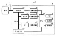
- an electronic sphygmomanometer (hereinafter abbreviated as sphygmomanometer) 1 according to the present embodiment includes an air bag (not shown) wound around a main body 2 and an upper arm, a wrist, or the like, which is a measurement site. And an arm band 5 enclosing them, which are connected by an air tube 10A.
- an operation unit 3 such as a switch and a display unit 4 for displaying measurement results and the like are arranged on the front surface of the main body 2.
- the operation unit 3 includes a switch 31 for instructing power ON / OFF and measurement start / stop, and a switch 32 for calling and displaying the recorded measurement value.
- armband 5 is connected to switching valve 24 via air tube 10A.
- the switching valve 24 is further connected to the pump 21, the valve 22, and the pressure sensor 23 via the air pipe 10 ⁇ / b> B in the main body 2.
- the switching valve 24 is connected to the drive circuit 25, the pump 21 is connected to the drive circuit 26, and the valve 22 is connected to the drive circuit 27, and each is driven by the drive circuit.
- the pressure sensor 23 and the drive circuits 25, 26 and 27 are all connected to a CPU 40 (Central Processing Unit). Further, the operation unit 3, the display unit 4, and the memory 6 are connected to the CPU 40.
- CPU 40 Central Processing Unit
- the memory 6 stores the measured blood pressure value, and also stores, as a program executed by the CPU 40, a program for performing a measurement operation and a program for performing an operation for a leak test described later. .
- the result of the leak test may be stored.
- the CPU 40 reads and executes the program from the memory 6 according to the operation signal input from the operation unit 3, and outputs a control signal to the drive circuit 26 and the drive circuit 27.
- the drive circuit 26 drives the pump 21 according to the control signal
- the drive circuit 27 drives the valve 22 according to the control signal.
- the switching valve 24 is a two-port valve, and includes a valve on each of the connection side with the air tube 10A and the connection side with the air tube 10B.
- the switching valve 24 is driven by the drive circuit 25, and the valve on the connection side with the air tube 10A and the valve on the connection side with the air tube 10B are opened or closed, respectively.
- the valve 22 is driven by a drive circuit 27 and is released or closed.
- the valve on the connection side of the switching valve 24 to the air tube 10B is opened, and the valve 22 on the connection side of the switching valve 24 to the air tube 10A and the valve 22 are closed, thereby forming a closed space in the air tube 10B.
- the pressure sensor 23 detects the pressure of the closed space.
- state 2 The state in which the closed space is formed by the air pipe 10B
- this closed space is referred to as “closed space 2”.
- the closed space 2 is a space in which the air bag (not shown) and the air tube 10A in the armband 5 are separated from the closed space 1.
- the pump 21 is driven by the drive circuit 26 and injects air into the closed space 1 or the closed space 2.
- the valve 22 is opened, the air in the closed space 1 or the closed space 2 is exhausted.
- the pressure sensor 23 inputs a signal indicating the detected pressure to the CPU 40.
- the CPU 40 executes the measurement program read from the memory 6 to calculate the blood pressure value of the person to be measured based on the signal input from the pressure sensor 23 and stores it as a measurement result in a predetermined area of the memory 6. .
- the CPU 40 determines the presence or absence of leak using a signal input from the pressure sensor 23 and stores the determination result in a predetermined area of the memory 6.
- the sphygmomanometer 1 performs a normal blood pressure measurement operation according to a blood pressure measurement program and an operation for a leak test according to a program for performing a leak test.
- the operation for a leak test in the sphygmomanometer 1 will be described with reference to FIGS. 3 and 4 to 12.
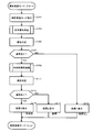
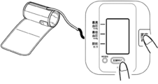
- the operation shown in the flowchart of FIG. 3 is started when the sphygmomanometer 1 is operated to press the switch 31 that turns on the power together with the other switches (switch 32 in FIG. 4) shown in FIG.
- the operation for instructing the start of the operation for the leak test may be another operation.
- the CPU 40 receives an input of an operation signal associated with the above operation from the operation unit 3, the CPU 40 reads and executes a program for performing a leak test from the memory 6. Thereby, the operation shown in the flowchart of FIG. 3 is started.
- step S101 the CPU 40 executes a process for causing the display unit 4 to display a screen indicating that the pre-stored air leak test is being performed.
- the display as shown in FIG. 5 is performed.
- step S103 the CPU 40 causes each unit to perform an operation for a leak test in accordance with the program.
- the air leakage test performed in step S103 is an inspection for the presence or absence of air leakage in the closed space 1 which is the entire space formed by the air bag (not shown) in the armband 5 and the air tubes 10A and 10B.
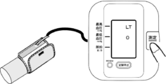
- step S103 the inspector first wraps the armband 5 around a cylinder of an appropriate size as shown in FIG. 6, and when the winding is completed, the switch 31 for starting measurement as shown in FIG. Press. Therefore, when the operation of step S103 is started, the CPU 40 preferably executes a process for causing the display unit 4 to display a screen that prompts the examiner to wrap the armband 5 around the cylinder and press the switch 31. For example, a screen for notifying that effect is displayed in FIG.
- step S103 the CPU 40 opens both valves of the switching valve 24 and outputs a control signal for closing the valve 22 to the drive circuits 25 and 27 to set the state 1 to form the closed space 1. . Thereafter, when receiving an operation signal indicating that the switch 31 has been pressed from the operation unit 3, the CPU 40 outputs a control signal for causing the pump 21 to inject air into the closed space 1 to the drive circuit 26.
- the internal pressure of is increased.
- the CPU 40 performs a leak test in accordance with a standard relating to a leak in JIS standards related to a sphygmomanometer. Specifically, according to JIS T4203-1990, after applying 200 mmHg and allowing to stand for 3 minutes, it is determined that there is no air leakage by confirming that the pressure does not drop more than 2 mmHg.
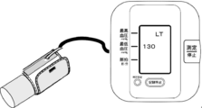
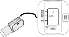
- the CPU 40 When the CPU 40 receives an operation signal indicating that the switch 31 has been pressed from the operation unit 3, the CPU 40 pressurizes the pump 21 by injecting air into the closed space 1 until the internal pressure becomes 200 mmHg. At that time, the CPU 40 preferably detects the pressure in the closed space 1 during pressurization based on a signal from the pressure sensor 23 at a predetermined interval and displays it on the display unit 4 as shown in FIG. As shown in FIG. 9, when the internal pressure in the closed space 1 reaches 200 mmHg, the CPU 40 outputs a control signal to the drive circuit 26 to stop driving the pump 21 and starts measuring time with a timer (not shown).
- the CPU 40 detects the internal pressure of the closed space 1 based on the signal from the pressure sensor 23 and displays it on the display unit 4, and leaks air in step S105. The presence or absence of is determined.
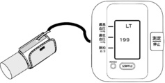
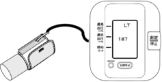
- step S107 when the decrease in the internal pressure of the closed space 1 after 200 minutes from the blockage of the pump 21 is within 2 mmHg, the CPU 40 determines that there is no air leakage in the closed space 1. (NO in step S107), and in step S108, as a “result 1”, a process for displaying on the display unit 4 a screen indicating that there is no leak stored in advance is performed, as shown in FIG. A screen is displayed on the display unit 4. And a series of operation
- step S107 when the decrease from 200 mmHg in the internal pressure of the closed space 1 after 3 minutes from the blockage of the pump 21 is larger than 2 mmHg, the CPU 40 determines that there is air leakage in the closed space 1. (YES in step S107), the process proceeds to step S109.
- step S109 When the operation of step S109 is started, the CPU 40 outputs a control signal for closing the valve on the connection side of the switching valve 24 to the air pipe 10A to 25 to shift from the state 1 to the state 2, and from the closed space 1 A closed space 2 is formed by separating an air bag (not shown) in the armband 5 and the air tube 10A.
- the CPU 40 pressurizes the closed space 2 until the internal pressure reaches 200 mmHg in the same manner as the operation in step S103, and the internal pressure of the closed space 2 after 3 minutes is transmitted from the pressure sensor 23.
- the air leakage determination in step S111 is performed.
- the air leakage determination in step S111 is the same as that in step S105.
- step S115 processing for displaying a screen indicating “result 2” on the display unit 4 is performed, and “result 2” is displayed.
- a display screen is displayed on the display unit 4.
- step S113 when the decrease from 200 mmHg in the internal pressure of the closed space 2 after 3 minutes from the blockage of the pump 21 is larger than 2 mmHg, the CPU 40 has an air leak in the closed space 1 and It is determined that there is also air leakage in the closed space 2 (YES in step S113), and in step S119, a process for displaying a screen indicating “Result 3” on the display unit 4 is performed, and a screen indicating “Result 3” is displayed. It is displayed on the display unit 4.
- step S113 There is leakage in the entire space formed by the closed space 1, that is, the air bag (not shown) in the armband 5 and the air tubes 10A and 10B, and the closed space 2, that is, the closed space formed by the air tube 10B. If it is determined that there is no air leakage (NO in step S113), there is no air leakage portion inside the main body 2 which is the air tube 10B, and an air bag (not shown) and an air tube in the armband 5 are used. It is determined that there is an air leakage place in the portion connected to the main body 2 that is 10A. Therefore, the above-mentioned “Result 2” is a result indicating that there is an air leak location in the portion connected to the main body 2. Therefore, preferably, in step S117, the CPU 40 causes the display unit 4 to display a screen indicating that the air leak location is in a portion connected to the main body 2 such as the armband 5 as shown in FIG.
- step S113 the CPU 40 causes the display unit 4 to display a screen similar to the screen illustrated in FIG.
- the sphygmomanometer 1 performs the above-described operation for the leak test, so that the user can perform the leak test with a simple operation even if the user does not have a special test device.
- the sphygmomanometer 1 main body is handed over to request a repair or inspection from the manufacturer. There is no need, and the leakage can be eliminated by purchasing or exchanging a part connected to the main body 2 such as the armband 5. Therefore, the inconvenience that the sphygmomanometer 1 cannot be used for a long time can be prevented.
- a blood leak test is performed on the sphygmomanometer 1 by a specific operation as shown in FIG.
- an operation for a leak test may be automatically executed at a predetermined timing.
- a display for prompting the implementation of the leak test may be displayed on the display unit 4.
- the sphygmomanometer 1 has a calendar function.
- the CPU 40 associates the execution date of the operation with the result (the above-mentioned “Result 1”, “Result 2”, or “Result 3”) of the memory 6.
- Store in a predetermined area The CPU 40 confirms the result of the air leak test stored in the memory 6 at a predetermined timing, and determines whether or not to perform an operation for the air leak test from the result.
- the predetermined timing include a timing at which an operation of pressing the switch 31 for turning on the power to perform normal blood pressure measurement is performed. Further, it may be after a series of blood pressure measurement operations.
- Judgment whether or not to perform the operation for the air leak test includes, for example, the case where the reference days have passed since the date of the previous air leak test or the case where the reference measurement count has been performed. Furthermore, a plurality of the above “reference days” may be stored according to the result of the previous leak test, and may be used according to the test result. Specifically, the “reference days” used when the result of the previous air leak test is air leak (“result 2” or “result 3”) is no air leak (“result 1”). Those longer than the “reference days” can be used. Because there is no leak because it is considered that the leak point has been repaired by determining that there is leak (“Result 2” or “Result 3”) in the previous leak test. This is because it is considered unnecessary to conduct leak tests at intervals as short as possible. The same applies to the “reference number of measurements”.
- the CPU 40 associates the information indicating that with the implementation date. And stored in a predetermined area of the memory 6. The CPU 40 can detect that the above repair or replacement has been performed by receiving a predetermined operation from the operation unit 3. Further, when a storage medium storing information for identifying the air tubes 10A and 10B, such as an IC chip, is provided in the connection part of the air tubes 10A and 10B, the connection part is provided with a reading mechanism for the storage medium. The CPU 40 can detect that the exchange has been performed based on the identification information read from the storage medium.
- the CPU 40 confirms the information indicating that the repair or replacement stored in the memory 6 has been performed at a predetermined timing, and if the reference number of days has passed since the date of the previous repair or replacement, It is determined that an operation for inspection is performed.
- the predetermined timing include a timing at which an operation of pressing the switch 31 for turning on the power to perform normal blood pressure measurement is performed. Further, it may be after a series of blood pressure measurement operations.
- the CPU 40 stores the blood pressure measurement result in a predetermined area of the memory 6 in association with the measurement date. Then, the CPU 40 confirms the measurement result stored in the memory 6 at a predetermined timing, and determines that the operation for the air leakage test is performed when the reference number of days has passed since the previous measurement date. To do.
- the CPU 40 further displays information indicating that a part connected to the main body 2 such as the armband 5 or the air pipe 10B inside the main body 2 has been repaired or replaced. And stored in a predetermined area of the memory 6. Then, the CPU 40 confirms the information and the measurement result indicating that the repair or replacement stored in the memory 6 has been performed at a predetermined timing, and the specified number of measurements have been performed from the date of the previous repair or replacement. If it is, it is determined that an operation for a leak test is performed.
- a leak test is performed at an appropriate timing, and if there is a leak point, correction or replacement can be performed quickly. Thereby, an accurate measurement result can be obtained. Further, when the result of the final leak test is leak, the reliability of the measurement result can be improved by preventing the blood pressure measurement from starting.
Landscapes
- Health & Medical Sciences (AREA)
- Life Sciences & Earth Sciences (AREA)
- Cardiology (AREA)
- Physics & Mathematics (AREA)
- Vascular Medicine (AREA)
- Engineering & Computer Science (AREA)
- Public Health (AREA)
- Veterinary Medicine (AREA)
- Biophysics (AREA)
- Pathology (AREA)
- Physiology (AREA)
- Biomedical Technology (AREA)
- Heart & Thoracic Surgery (AREA)
- Medical Informatics (AREA)
- Molecular Biology (AREA)
- Surgery (AREA)
- Animal Behavior & Ethology (AREA)
- General Health & Medical Sciences (AREA)
- Dentistry (AREA)
- Ophthalmology & Optometry (AREA)
- General Physics & Mathematics (AREA)
- Measuring Pulse, Heart Rate, Blood Pressure Or Blood Flow (AREA)
Abstract
Description
変形例1にかかる血圧計1はカレンダー機能を備える。CPU40は、上述の漏気検査のための動作が行なわれると、その結果(上述の「結果1」、「結果2」、または「結果3」)に当該動作の実施日を関連付けてメモリ6の所定領域に記憶する。CPU40は、所定のタイミングでメモリ6に記憶されている漏気検査の結果を確認し、その結果から漏気検査のための動作を行なうか否かを判断する。上記所定のタイミングとしては、たとえば、通常の血圧測定を行なうために電源をONするためのスイッチ31を押下する動作が行なわれたタイミングが挙げられる。また、一連の血圧測定動作が行なわれた後であってもよい。
変形例2において、CPU40は、腕帯5などの本体2に接続される部分または本体2内部のエア管10Bなどの修繕や交換が行なわれた際に、その旨を示す情報に実施日と関連付けてメモリ6の所定領域に記憶する。CPU40は、上の修繕や交換が行なわれたことを、所定の操作を操作部3から受付けることで検出することができる。また、エア管10A,10Bの接続部にICチップなどの、当該エア管10A,10Bを識別する情報を記憶した記憶媒体が備えられている場合、接続部にそれら記憶媒体の読取機構を備えて、CPU40は、記憶媒体から読取った識別情報に基づいて交換が行なわれたことを検出することができる。
変形例3において、CPU40は、血圧測定の結果を測定日と関連付けてメモリ6の所定領域に記憶する。そして、CPU40は、所定のタイミングでメモリ6に記憶されている測定結果を確認し、先の測定の実施日から基準日数が経過している場合に、漏気検査のための動作を行なうと判断する。
Claims (6)
- 閉空間に接続され、前記閉空間の内圧を検出するための圧力センサ(23)と、
前記閉空間に対する流体の注入および排気を制御するための制御装置(40)と、
演算装置(40)とを含み、
前記演算装置は、
前記内圧の変化に基づいて、前記閉空間に含まれる流体袋が装着された測定部位の血圧を算出するための演算処理と、
前記内圧の変化に基づいて、前記閉空間からの漏気の有無を判定するための判定処理とを実行する、電子血圧計。 - 前記制御装置は、前記演算装置で前記判定処理を実行する際に、前記閉空間に所定の圧力まで流体を注入した後に、規定された時間前記流体の注入および排気を停止し、
前記演算装置は、前記判定処理において前記規定された時間内の前記内圧の変化に基づいて、前記閉空間からの漏気の有無を判定する、請求の範囲第1項に記載の電子血圧計。 - 前記閉空間は、前記流体袋を含む第1の空間と、前記流体袋を含まない第2の空間とを含み、
前記圧力センサが接続される閉空間を前記第1の空間または前記第2の空間に切替えるための切替機構(24)をさらに含み、
前記制御装置は、前記演算装置で前記判定処理を実行する際に、前記切替機構での前記切替を制御し、
前記演算装置は、前記判定処理において、さらに、漏気箇所を含む空間を特定する、請求の範囲第1項に記載の電子血圧計。 - 前記第1の空間は前記流体袋と前記流体袋に流体を注入するためのすべての管(10A,10B)とからなる空間であり、
前記第2の空間は、前記第1の空間から前記流体袋と前記流体袋に直接接続される管とを除いた空間である、請求の範囲第3項に記載の電子血圧計。 - 前記制御装置は、前記演算装置が前記判定処理の結果、前記第1の空間の前記内圧の変化に基づいて前記第1の空間に漏気があると判定した場合に、前記切替機構を制御して前記第1の空間を前記第2の空間に切替え、
前記演算装置は、前記判定処理において前記第1の空間についての漏気の有無を判定し、前記第1の空間に漏気があると判定した場合に、前記第2の空間についての漏気の有無を判定し、前記第1の空間の漏気の有無の判定結果と、前記第2の空間の漏気の有無の判定結果とから、漏気箇所が、前記流体袋と前記流体袋に直接接続される管とからなる空間にあるか、前記第1の空間から前記流体袋と前記流体袋に直接接続される管とを除いた空間にあるか、を特定する、請求の範囲第4項に記載の電子血圧計。 - 前記演算装置の前記判定処理における前記漏気の有無の判定の実施日を記憶するための記憶装置(6)をさらに含み、
前記制御装置は、直前の前記実施日からの経過、またはこれまでの測定回数に基づいて、前記演算装置で前記判定処理を行なって前記漏気の有無を判定するタイミングを判断する、請求の範囲第1項に記載の電子血圧計。
Priority Applications (4)
| Application Number | Priority Date | Filing Date | Title |
|---|---|---|---|
| RU2011128445/14A RU2517584C2 (ru) | 2008-12-09 | 2009-12-03 | Электронный сфигмоманометр, подтверждающий утечку воздуха |
| CN200980149518.9A CN102245088B (zh) | 2008-12-09 | 2009-12-03 | 能够确认漏气的电子血压计 |
| DE112009003696.1T DE112009003696B4 (de) | 2008-12-09 | 2009-12-03 | Elektronisches Blutdruckmessgerät, welches einen Luftverlust bestätigen kann |
| US13/155,920 US8900156B2 (en) | 2008-12-09 | 2011-06-08 | Electronic sphygmomanometer that can confirm air leakage |
Applications Claiming Priority (2)
| Application Number | Priority Date | Filing Date | Title |
|---|---|---|---|
| JP2008313621A JP5239806B2 (ja) | 2008-12-09 | 2008-12-09 | 電子血圧計 |
| JP2008-313621 | 2008-12-09 |
Related Child Applications (1)
| Application Number | Title | Priority Date | Filing Date |
|---|---|---|---|
| US13/155,920 Continuation US8900156B2 (en) | 2008-12-09 | 2011-06-08 | Electronic sphygmomanometer that can confirm air leakage |
Publications (1)
| Publication Number | Publication Date |
|---|---|
| WO2010067752A1 true WO2010067752A1 (ja) | 2010-06-17 |
Family
ID=42242740
Family Applications (1)
| Application Number | Title | Priority Date | Filing Date |
|---|---|---|---|
| PCT/JP2009/070338 Ceased WO2010067752A1 (ja) | 2008-12-09 | 2009-12-03 | 漏気を確認できる電子血圧計 |
Country Status (6)
| Country | Link |
|---|---|
| US (1) | US8900156B2 (ja) |
| JP (1) | JP5239806B2 (ja) |
| CN (1) | CN102245088B (ja) |
| DE (1) | DE112009003696B4 (ja) |
| RU (1) | RU2517584C2 (ja) |
| WO (1) | WO2010067752A1 (ja) |
Cited By (3)
| Publication number | Priority date | Publication date | Assignee | Title |
|---|---|---|---|---|
| JP2010136767A (ja) * | 2008-12-09 | 2010-06-24 | Omron Healthcare Co Ltd | 電子血圧計 |
| WO2020203267A1 (ja) * | 2019-04-03 | 2020-10-08 | オムロンヘルスケア株式会社 | 血圧計 |
| JP2022158257A (ja) * | 2021-04-01 | 2022-10-17 | 株式会社北浜製作所 | 検査装置 |
Families Citing this family (14)
| Publication number | Priority date | Publication date | Assignee | Title |
|---|---|---|---|---|
| JP2012029793A (ja) * | 2010-07-29 | 2012-02-16 | Omron Healthcare Co Ltd | 電子血圧計用モジュールおよび電子血圧計 |
| USD737855S1 (en) | 2013-06-17 | 2015-09-01 | Covidien Lp | Display screen with a transitional venous refill detection icon |
| USD760728S1 (en) | 2013-06-17 | 2016-07-05 | Covidien Lp | Display screen with graphical user interface for patient use meter reset |
| USD774057S1 (en) * | 2013-06-17 | 2016-12-13 | Covidien Lp | Display screen with a graphical user interface for compliance monitoring |
| USD737328S1 (en) | 2013-06-17 | 2015-08-25 | Covidien Lp | Display screen with graphical user interface for venous refill detection |
| USD737327S1 (en) | 2013-06-17 | 2015-08-25 | Covidien Lp | Display screen with a transitional leak detection icon |
| EP3163280A4 (en) * | 2014-09-18 | 2017-08-09 | Takashin Co., Ltd. | Fluid path inspection device and fluid path inspection method |
| NL2016717B1 (en) * | 2016-05-02 | 2017-11-10 | Oxipack Holding B V | Method and system for measuring leak tightness of a sealed package |
| CN105919581A (zh) * | 2016-05-27 | 2016-09-07 | 常州市盈顺电子有限公司 | 家用自动血压测量仪 |
| JP6658332B2 (ja) * | 2016-06-23 | 2020-03-04 | オムロンヘルスケア株式会社 | 血圧計 |
| CN108167172B (zh) * | 2017-12-20 | 2020-01-24 | 广州视源电子科技股份有限公司 | 气泵的测试方法、装置、设备、系统及存储介质 |
| JP7102334B2 (ja) * | 2018-12-27 | 2022-07-19 | オムロンヘルスケア株式会社 | 血圧測定装置充電用コネクタ |
| US20230000262A1 (en) * | 2020-03-23 | 2023-01-05 | Shenzhen Onethird Sleep Technology Co., Ltd | Air bag self-checking system and method |
| CN111436997A (zh) * | 2020-04-21 | 2020-07-24 | 重庆大学附属肿瘤医院 | 一种用于血管内皮功能无创检测的自适应安全阻断装置 |
Citations (2)
| Publication number | Priority date | Publication date | Assignee | Title |
|---|---|---|---|---|
| JP2002078686A (ja) * | 2000-09-11 | 2002-03-19 | Citizen Watch Co Ltd | 血圧計 |
| JP2008241410A (ja) * | 2007-03-27 | 2008-10-09 | Tanita Corp | 生化学測定器の状態を表示できる生化学測定器スタンド |
Family Cites Families (13)
| Publication number | Priority date | Publication date | Assignee | Title |
|---|---|---|---|---|
| US4669485A (en) | 1984-02-17 | 1987-06-02 | Cortronic Corporation | Apparatus and method for continuous non-invasive cardiovascular monitoring |
| US5025793A (en) * | 1986-10-07 | 1991-06-25 | Richley Edward A | Finger blood pressure measurement system |
| US4924873A (en) * | 1988-03-23 | 1990-05-15 | Spacelabs, Inc. | Pneumatic control system for neonatal blood pressure monitoring |
| US4953396A (en) * | 1989-08-18 | 1990-09-04 | General Mills, Inc. | Leak detector for containers |
| US5797850A (en) | 1993-11-09 | 1998-08-25 | Medwave, Inc. | Method and apparatus for calculating blood pressure of an artery |
| JP3525005B2 (ja) * | 1996-01-26 | 2004-05-10 | 東京瓦斯株式会社 | 既設配管系の漏洩検知方式 |
| RU2210974C2 (ru) * | 2001-07-31 | 2003-08-27 | Казанский государственный технический университет им. А.Н. Туполева | Установка для поверки автоматизированных средств измерений артериального давления и частоты пульса |
| JP4467263B2 (ja) | 2002-09-20 | 2010-05-26 | 日本精密測器株式会社 | 健康指標測定のための電子機器及びその制御方法 |
| AU2002951984A0 (en) * | 2002-10-10 | 2002-10-31 | Compumedics Limited | Sleep quality and auto cpap awakening |
| KR100414360B1 (ko) | 2002-11-08 | 2004-01-16 | 주식회사 휴먼메디텍 | 플라즈마 처리기가 부착된 멸균장치 및 멸균방법 |
| JP3925858B2 (ja) | 2002-11-08 | 2007-06-06 | 日本精密測器株式会社 | 非観血式血圧計 |
| US20100010357A1 (en) * | 2008-07-09 | 2010-01-14 | Morris Ostrowiecki | Disposable air bag for a blood pressure measuring device and a method of making the same |
| JP5239806B2 (ja) * | 2008-12-09 | 2013-07-17 | オムロンヘルスケア株式会社 | 電子血圧計 |
-
2008
- 2008-12-09 JP JP2008313621A patent/JP5239806B2/ja active Active
-
2009
- 2009-12-03 WO PCT/JP2009/070338 patent/WO2010067752A1/ja not_active Ceased
- 2009-12-03 RU RU2011128445/14A patent/RU2517584C2/ru active
- 2009-12-03 CN CN200980149518.9A patent/CN102245088B/zh active Active
- 2009-12-03 DE DE112009003696.1T patent/DE112009003696B4/de active Active
-
2011
- 2011-06-08 US US13/155,920 patent/US8900156B2/en active Active
Patent Citations (2)
| Publication number | Priority date | Publication date | Assignee | Title |
|---|---|---|---|---|
| JP2002078686A (ja) * | 2000-09-11 | 2002-03-19 | Citizen Watch Co Ltd | 血圧計 |
| JP2008241410A (ja) * | 2007-03-27 | 2008-10-09 | Tanita Corp | 生化学測定器の状態を表示できる生化学測定器スタンド |
Cited By (7)
| Publication number | Priority date | Publication date | Assignee | Title |
|---|---|---|---|---|
| JP2010136767A (ja) * | 2008-12-09 | 2010-06-24 | Omron Healthcare Co Ltd | 電子血圧計 |
| WO2020203267A1 (ja) * | 2019-04-03 | 2020-10-08 | オムロンヘルスケア株式会社 | 血圧計 |
| JP2020168205A (ja) * | 2019-04-03 | 2020-10-15 | オムロンヘルスケア株式会社 | 血圧計 |
| JP7147666B2 (ja) | 2019-04-03 | 2022-10-05 | オムロンヘルスケア株式会社 | 血圧計 |
| US12336794B2 (en) | 2019-04-03 | 2025-06-24 | Omron Healthcare Co., Ltd. | Sphygmomanometer |
| JP2022158257A (ja) * | 2021-04-01 | 2022-10-17 | 株式会社北浜製作所 | 検査装置 |
| JP7652612B2 (ja) | 2021-04-01 | 2025-03-27 | 株式会社北浜製作所 | 検査装置 |
Also Published As
| Publication number | Publication date |
|---|---|
| CN102245088A (zh) | 2011-11-16 |
| RU2517584C2 (ru) | 2014-05-27 |
| US8900156B2 (en) | 2014-12-02 |
| RU2011128445A (ru) | 2013-01-20 |
| DE112009003696B4 (de) | 2023-12-28 |
| US20120143069A1 (en) | 2012-06-07 |
| DE112009003696T5 (de) | 2012-11-08 |
| JP2010136767A (ja) | 2010-06-24 |
| CN102245088B (zh) | 2014-07-30 |
| JP5239806B2 (ja) | 2013-07-17 |
Similar Documents
| Publication | Publication Date | Title |
|---|---|---|
| JP5239806B2 (ja) | 電子血圧計 | |
| CN102325492B (zh) | 管理装置、管理系统以及管理方法 | |
| US10201285B2 (en) | Blood pressure measurement device including wrapping strength evaluation capabilities | |
| CN100441140C (zh) | 血压测定用带的卷绕控制装置和方法 | |
| EP1486764A1 (en) | Leak tester | |
| JP3483253B2 (ja) | 圧力計測方法及び装置 | |
| US9022944B2 (en) | Electronic sphygmomanometer | |
| CN103228204B (zh) | 带有简易血压确认功能的电子血压计 | |
| CN109310350A (zh) | 血压计 | |
| JP2002078686A (ja) | 血圧計 | |
| JP2010099384A (ja) | 血圧計 | |
| JP4278722B2 (ja) | ガス遮断装置 | |
| JP6193161B2 (ja) | 血圧計試験装置、その制御方法及び血圧計システム | |
| JP5228620B2 (ja) | 血圧測定装置 | |
| JP5867113B2 (ja) | 電子血圧計および電子血圧計の制御方法 | |
| JP4094704B2 (ja) | トラップ及びバルブの診断装置 | |
| JP2011152307A (ja) | 電子血圧計およびその制御方法 | |
| JPH07178065A (ja) | 血圧計の検査方法と血圧計 | |
| CN100459930C (zh) | 电子血压计的校正方法及其装置 | |
| CN221147945U (zh) | 用于加压医疗器械的便携式检测装置 | |
| JP5985855B2 (ja) | 生体検査装置、進行状況表示方法および進行状況表示プログラム | |
| WO2025187170A1 (ja) | 血圧測定装置、血圧測定方法及び血圧測定プログラム | |
| JPH04156820A (ja) | 電子血圧計 | |
| CN111990982A (zh) | 血压采集装置、处理系统及血压采集方法 | |
| JP2006322867A (ja) | 容器検査方法及び装置 |
Legal Events
| Date | Code | Title | Description |
|---|---|---|---|
| WWE | Wipo information: entry into national phase |
Ref document number: 200980149518.9 Country of ref document: CN |
|
| 121 | Ep: the epo has been informed by wipo that ep was designated in this application |
Ref document number: 09831856 Country of ref document: EP Kind code of ref document: A1 |
|
| DPE1 | Request for preliminary examination filed after expiration of 19th month from priority date (pct application filed from 20040101) | ||
| WWE | Wipo information: entry into national phase |
Ref document number: 1120090036961 Country of ref document: DE Ref document number: 112009003696 Country of ref document: DE |
|
| WWE | Wipo information: entry into national phase |
Ref document number: 2011128445 Country of ref document: RU |
|
| 122 | Ep: pct application non-entry in european phase |
Ref document number: 09831856 Country of ref document: EP Kind code of ref document: A1 |