WO2010064524A1 - ハフニウムアミド錯体の製造方法及びハフニウム含有酸化膜 - Google Patents
ハフニウムアミド錯体の製造方法及びハフニウム含有酸化膜 Download PDFInfo
- Publication number
- WO2010064524A1 WO2010064524A1 PCT/JP2009/069157 JP2009069157W WO2010064524A1 WO 2010064524 A1 WO2010064524 A1 WO 2010064524A1 JP 2009069157 W JP2009069157 W JP 2009069157W WO 2010064524 A1 WO2010064524 A1 WO 2010064524A1
- Authority
- WO
- WIPO (PCT)
- Prior art keywords
- hafnium
- fraction
- concentration
- complex
- tertiary
- Prior art date
- Legal status (The legal status is an assumption and is not a legal conclusion. Google has not performed a legal analysis and makes no representation as to the accuracy of the status listed.)
- Ceased
Links
Images
Classifications
-
- C—CHEMISTRY; METALLURGY
- C07—ORGANIC CHEMISTRY
- C07F—ACYCLIC, CARBOCYCLIC OR HETEROCYCLIC COMPOUNDS CONTAINING ELEMENTS OTHER THAN CARBON, HYDROGEN, HALOGEN, OXYGEN, NITROGEN, SULFUR, SELENIUM OR TELLURIUM
- C07F7/00—Compounds containing elements of Groups 4 or 14 of the Periodic Table
-
- C—CHEMISTRY; METALLURGY
- C07—ORGANIC CHEMISTRY
- C07C—ACYCLIC OR CARBOCYCLIC COMPOUNDS
- C07C211/00—Compounds containing amino groups bound to a carbon skeleton
- C07C211/65—Metal complexes of amines
-
- C—CHEMISTRY; METALLURGY
- C07—ORGANIC CHEMISTRY
- C07C—ACYCLIC OR CARBOCYCLIC COMPOUNDS
- C07C209/00—Preparation of compounds containing amino groups bound to a carbon skeleton
- C07C209/68—Preparation of compounds containing amino groups bound to a carbon skeleton from amines, by reactions not involving amino groups, e.g. reduction of unsaturated amines, aromatisation, or substitution of the carbon skeleton
-
- C—CHEMISTRY; METALLURGY
- C23—COATING METALLIC MATERIAL; COATING MATERIAL WITH METALLIC MATERIAL; CHEMICAL SURFACE TREATMENT; DIFFUSION TREATMENT OF METALLIC MATERIAL; COATING BY VACUUM EVAPORATION, BY SPUTTERING, BY ION IMPLANTATION OR BY CHEMICAL VAPOUR DEPOSITION, IN GENERAL; INHIBITING CORROSION OF METALLIC MATERIAL OR INCRUSTATION IN GENERAL
- C23C—COATING METALLIC MATERIAL; COATING MATERIAL WITH METALLIC MATERIAL; SURFACE TREATMENT OF METALLIC MATERIAL BY DIFFUSION INTO THE SURFACE, BY CHEMICAL CONVERSION OR SUBSTITUTION; COATING BY VACUUM EVAPORATION, BY SPUTTERING, BY ION IMPLANTATION OR BY CHEMICAL VAPOUR DEPOSITION, IN GENERAL
- C23C16/00—Chemical coating by decomposition of gaseous compounds, without leaving reaction products of surface material in the coating, i.e. chemical vapour deposition [CVD] processes
- C23C16/22—Chemical coating by decomposition of gaseous compounds, without leaving reaction products of surface material in the coating, i.e. chemical vapour deposition [CVD] processes characterised by the deposition of inorganic material, other than metallic material
- C23C16/30—Deposition of compounds, mixtures or solid solutions, e.g. borides, carbides, nitrides
- C23C16/40—Oxides
-
- C—CHEMISTRY; METALLURGY
- C23—COATING METALLIC MATERIAL; COATING MATERIAL WITH METALLIC MATERIAL; CHEMICAL SURFACE TREATMENT; DIFFUSION TREATMENT OF METALLIC MATERIAL; COATING BY VACUUM EVAPORATION, BY SPUTTERING, BY ION IMPLANTATION OR BY CHEMICAL VAPOUR DEPOSITION, IN GENERAL; INHIBITING CORROSION OF METALLIC MATERIAL OR INCRUSTATION IN GENERAL
- C23C—COATING METALLIC MATERIAL; COATING MATERIAL WITH METALLIC MATERIAL; SURFACE TREATMENT OF METALLIC MATERIAL BY DIFFUSION INTO THE SURFACE, BY CHEMICAL CONVERSION OR SUBSTITUTION; COATING BY VACUUM EVAPORATION, BY SPUTTERING, BY ION IMPLANTATION OR BY CHEMICAL VAPOUR DEPOSITION, IN GENERAL
- C23C16/00—Chemical coating by decomposition of gaseous compounds, without leaving reaction products of surface material in the coating, i.e. chemical vapour deposition [CVD] processes
- C23C16/22—Chemical coating by decomposition of gaseous compounds, without leaving reaction products of surface material in the coating, i.e. chemical vapour deposition [CVD] processes characterised by the deposition of inorganic material, other than metallic material
- C23C16/30—Deposition of compounds, mixtures or solid solutions, e.g. borides, carbides, nitrides
- C23C16/40—Oxides
- C23C16/401—Oxides containing silicon
-
- C—CHEMISTRY; METALLURGY
- C23—COATING METALLIC MATERIAL; COATING MATERIAL WITH METALLIC MATERIAL; CHEMICAL SURFACE TREATMENT; DIFFUSION TREATMENT OF METALLIC MATERIAL; COATING BY VACUUM EVAPORATION, BY SPUTTERING, BY ION IMPLANTATION OR BY CHEMICAL VAPOUR DEPOSITION, IN GENERAL; INHIBITING CORROSION OF METALLIC MATERIAL OR INCRUSTATION IN GENERAL
- C23C—COATING METALLIC MATERIAL; COATING MATERIAL WITH METALLIC MATERIAL; SURFACE TREATMENT OF METALLIC MATERIAL BY DIFFUSION INTO THE SURFACE, BY CHEMICAL CONVERSION OR SUBSTITUTION; COATING BY VACUUM EVAPORATION, BY SPUTTERING, BY ION IMPLANTATION OR BY CHEMICAL VAPOUR DEPOSITION, IN GENERAL
- C23C16/00—Chemical coating by decomposition of gaseous compounds, without leaving reaction products of surface material in the coating, i.e. chemical vapour deposition [CVD] processes
- C23C16/22—Chemical coating by decomposition of gaseous compounds, without leaving reaction products of surface material in the coating, i.e. chemical vapour deposition [CVD] processes characterised by the deposition of inorganic material, other than metallic material
- C23C16/30—Deposition of compounds, mixtures or solid solutions, e.g. borides, carbides, nitrides
- C23C16/40—Oxides
- C23C16/405—Oxides of refractory metals or yttrium
Definitions
- the present invention is used as a hafnium film-forming raw material for hafnium-containing oxide films (HfO 2 , Hf x Si y O z , Hf x Al y O z, etc.), which are attracting attention as next-generation high-k gate oxide films in semiconductor manufacturing.
- the present invention relates to a promising method for producing a hafnium amide complex and a hafnium-containing oxide film produced using the method.
- SiO 2 has been used for many years as a gate oxide film in semiconductor manufacturing. This is because it has been possible to cope with the increase in the operation speed of the device due to the high integration of the semiconductor by making the SiO 2 film thinner.
- the device operating speed has been further increased.
- the physical limit has been approached to make SiO 2 thinner, and the speed will be further increased. This has become difficult. Therefore, a hafnium-containing oxide film has attracted attention as a gate oxide film that replaces SiO 2 .
- Hafnium-containing oxide film because several times higher dielectric constant compared to the SiO 2, it is possible to increase compared with the physical thickness corresponding to the speed of the operating speed of the device to SiO 2.
- a physical vapor deposition method Physical Vapor Deposition, hereinafter abbreviated as PVD method
- a chemical vapor deposition method Ceral Vapor Deposition, hereinafter abbreviated as CVD method
- PVD method Physical Vapor Deposition
- CVD method chemical Vapor Deposition
- the current mainstream is to use the CVD method as a method for forming the gate oxide film.
- a hafnium film-forming raw material having a high vapor pressure is required.
- a hafnium amide complex is relatively high in volatility and is a semiconductor gate oxide film by a CVD method.
- the application has been expanded as a raw material for forming a hafnium-containing oxide film.
- a method for producing the hafnium amide complex a method of reacting a hafnium tetrachloride (HfCl 4) and lithium alkylamide (LiNR 4 R 5) in an organic solvent is generally used.
- Non-Patent Document 1 tetrakisdiethylamide hafnium ⁇ Hf [N (CH 2 CH 3 ) 2 ] 4 ⁇ is reacted by reacting hafnium tetrachloride (HfCl 4 ) with lithium diethylamide [LiN (CH 2 CH 3 ) 2 ] in a hexane solvent.
- HfCl 4 hafnium tetrachloride
- LiN (CH 2 CH 3 ) 2 lithium diethylamide
- the hafnium amide complex that is a raw material for forming the film is also required to be a high-purity product.
- the zirconium component derived from the raw material is usually contained at a high concentration of about 1000 to 5000 ppm by mass. This is because hafnium and zirconium are the same group elements and have similar chemical properties due to lanthanoid contraction, so that separation is very difficult.
- zirconium oxide has lower heat resistance than hafnium oxide, and depending on the zirconium impurity concentration in the hafnium film forming raw material, zirconium oxide is incorporated into the film, resulting in an accidental failure of the device. Therefore, it is desired to reduce the zirconium concentration in the film. Therefore, it is important to use a hafnium film-forming raw material with a reduced zirconium concentration in securing device reliability (Non-patent Document 2).
- Patent Document 1 a method for producing a hafnium film-forming raw material having a reduced zirconium component
- a method for producing a hafnium amide complex by vacuum distillation Patent Document 1, Patent Document 2), a method of manufacturing by light irradiation or circulation of a chelate-supported column (Patent) Reference 3), a method for producing a hafnium film-forming raw material after recrystallization with an organic solvent containing an ether bond in hafnium halide (Patent Document 4), an additive such as CF 3 SO 3 H to a hafnium amide complex
- Patent Document 5 a method for producing a hafnium amide complex that performs distillation under reduced pressure.
- Patent Document 2 Japanese Patent Application Laid-Open No. 2005-298467
- a zirconium component in tetrakisdimethylamide hafnium is separated by reduced-pressure precision distillation by reduced-pressure precision distillation, but the difference in vapor pressure between the hafnium component and the zirconium component is determined.
- the ligand of the hafnium amide complex is limited to tetrakisdimethylamido hafnium having a dimethylamino group and cannot be applied to hafnium amide complexes such as tetrakisethylmethylamido hafnium and tetrakisdiethylamido hafnium.
- hafnium amide complexes such as tetrakisethylmethylamido hafnium and tetrakisdiethylamido hafnium.
- JP 2005-314785 A Patent Document 3
- JP 2007-0051042 A Patent Document 4
- An object of the present invention is to provide a method for easily producing a hafnium amide complex suitable as a semiconductor film forming material capable of providing a hafnium-containing oxide film in a high yield.
- the present inventors have added a lithium alkylamide to a tertiary hafnium alkoxide complex, reacted, and then subjected to a vacuum distillation operation to obtain a hafnium amide complex.
- the present inventors have found a method that can be easily produced in a high yield and have reached the present invention.
- a lithium alkylamide represented by the general formula: Li (NR 4 R 5 ) is added to a tertiary hafnium alkoxide complex represented by the general formula: Hf [O (CR 1 R 2 R 3 )] 4.
- the present invention provides a hafnium-containing oxide film produced by chemical vapor deposition using the hafnium amide complex produced by the above production method as a hafnium source.
- a hafnium amide complex can be easily produced in a high yield.
- the present invention can provide a hafnium-containing oxide film having a reduced zirconium concentration in the film.
- the present invention is applied to a hafnium amide complex used for applications requiring high purity such as a semiconductor manufacturing process.
- the hafnium amide complex in the present invention is used, for example, as a CVD material for forming a high dielectric constant gate oxide film in a semiconductor manufacturing process, and is represented by a general formula: Hf (NR 4 R 5 ) 4. It is a hafnium amide complex (in the formula, R 4 and R 5 are each independently one of a methyl group and an ethyl group).
- a lithium alkylamide is added to a tertiary hafnium alkoxide complex, the tertiary hafnium alkoxide complex is converted into a hafnium amide complex, and the lithium alkylamide is converted into a lithium alkoxide, and then the hafnium amide complex is distilled under reduced pressure.
- isolating By isolating.
- the zirconium content in the hafnium amide complex produced according to the present invention can be produced from the zirconium molar concentration of the tertiary hafnium alkoxide complex as a raw material without being concentrated in the production process.
- tetra (2-methyl-2-pentanoxy) hafnium ⁇ Hf [OC (CH 3 ) 2 (CH 2 CH 2 CH 3 )] 4 ⁇ as a tertiary hafnium alkoxide complex has a zirconium concentration of 638 molppm (molecular weight 583).
- the zirconium concentration is A hafnium amide complex corresponding to approximately 638 mol ppm (141 mass ppm) is obtained.
- the conversion from the mass concentration of zirconium to the molar concentration of zirconium was performed by the following formula 1.
- zirconium molar concentration zirconium mass concentration ⁇ (molecular weight of hafnium component / atomic weight of zirconium)
- the zirconium concentration in the film is 300 mass ppm or less. It is preferable to control to 30 ppm by mass or less, more preferably 3 ppm by mass or less.
- the zirconium concentration in the hafnium amide complex which is a semiconductor film forming material is 100 ppm by mass or less, more preferably 10 ppm by mass. In the following, it is more preferable to set it to 1 mass ppm or less.
- hafnium alkoxide complex a tertiary hafnium alkoxide complex which has a large steric hindrance of the ligand and forms a monomer is used.
- a primary hafnium alkoxide complex such as tetraethoxyhafnium [Hf (OCH 2 CH 3 ) 4 ] or a secondary hafnium alkoxide complex such as tetraisopropoxy hafnium ⁇ Hf [OCH (CH 3 ) 2 ] 4 ⁇ is used.
- a primary hafnium alkoxide complex such as tetraethoxyhafnium [Hf (OCH 2 CH 3 ) 4 ] or a secondary hafnium alkoxide complex such as tetraisopropoxy hafnium ⁇ Hf [OCH (CH 3 ) 2 ] 4 ⁇ is used.
- the hafnium alkoxide complex forms a multimer, and thus the reaction does not proceed sufficiently.
- the ligands R 1 , R 2 and R 3 of the tertiary hafnium alkoxide complex represented by the general formula: Hf [O (CR 1 R 2 R 3 )] 4 are each independently a phenyl group, a benzyl group, Represents any one of primary, secondary or tertiary alkyl groups having 1 to 6 carbon atoms, and R 1 , R 2 and R 3 are all methyl groups, and R 1 , R 2 and R 3 When any one of these is an ethyl group and the other two are methyl groups, it is preferable to use those which are excluded.
- a ligand is not versatile and economically unpreferable.
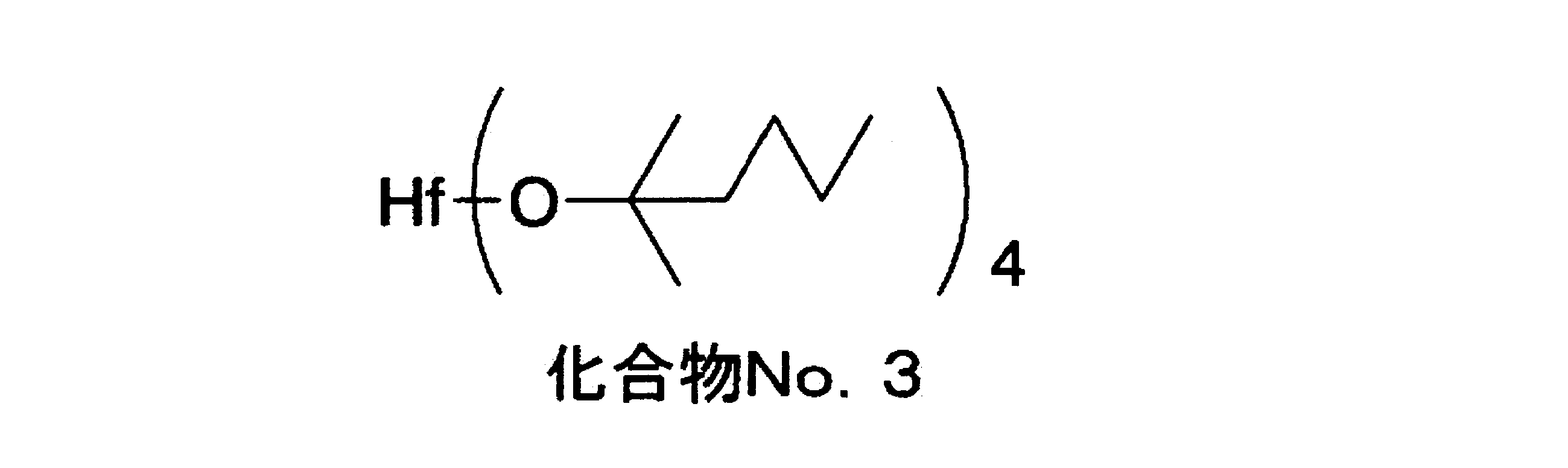
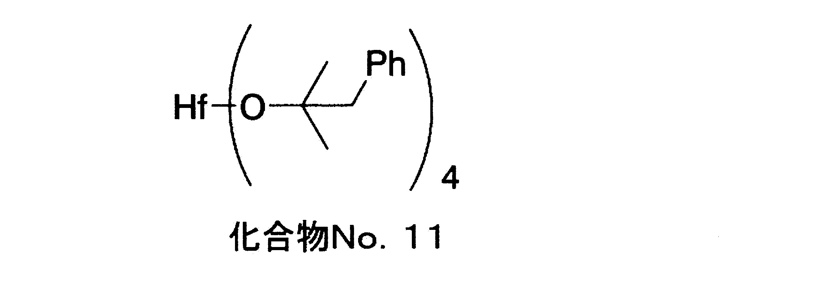
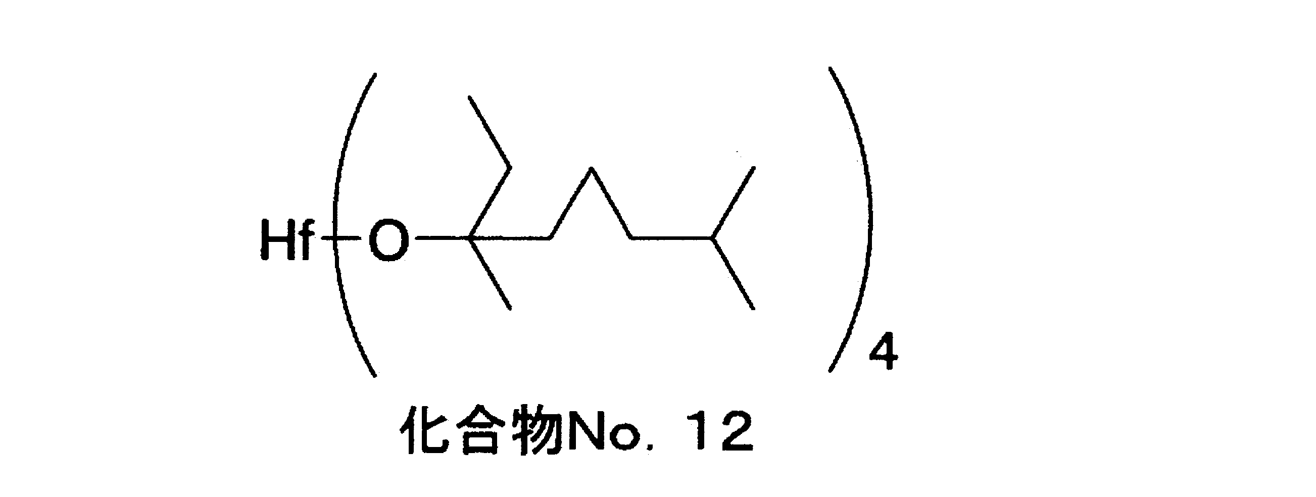
- tertiary hafnium alkoxide complex examples include the following compound Nos. 1-No. 12 is mentioned.
- the alcoholic form of the ligand is a compound No. 3 which is a tertiary hafnium alkoxide complex that is useful as a fragrance and is available at low cost. 11 or Compound No. 12 is preferred.
- the production of the tertiary hafnium alkoxide complex is not particularly limited and a known method can be used, but as described above, it is preferable to use a tertiary hafnium alkoxide complex having a low zirconium concentration.
- a tertiary hafnium alkoxide complex having a low zirconium concentration can be obtained by using the method described in Japanese Patent Application No. 2008-131124, which is an unpublished prior application at the time of the present application.
- the lithium alkylamide to be used has the same substituent as the amide ligand of the target product hafnium amide complex. That is, when tetrakisdiethylamide hafnium is produced, lithium alkylamide is used as lithium diethylamide, and when tetrakisdimethylamide hafnium is produced, lithium alkylamide is used as lithium dimethylamide.
- the amount of the lithium alkylamide used is preferably 1 to 10 equivalents relative to 1 equivalent of the tertiary hafnium alkoxide complex represented by the general formula: Hf [O (CR 1 R 2 R 3 )] 4 .
- the amount is less than 1 equivalent, the tertiary hafnium alkoxide complex may remain, resulting in a decrease in yield. Even when the amount is more than 10 equivalents, improvement in yield cannot be expected and it is not economical.
- Lithium alkylamide is a powdered solid at room temperature, but it can be added to a tertiary hafnium alkoxide complex represented by the above general formula: Hf [O (CR 1 R 2 R 3 )] 4 as a solid, or an organic compound such as ether. You may add in this tertiary hafnium alkoxide complex in the state melt
- the temperature at which the lithium alkylamide is added to the tertiary hafnium alkoxide complex represented by the general formula: Hf [O (CR 1 R 2 R 3 )] 4 is preferably within the range of ⁇ 78 to 200 ° C. More preferably, it is within the range of 0 ° C to 100 ° C. When added at a temperature higher than 200 ° C., the lithium alkylamide may be decomposed by heat.
- lithium alkylamide stir with a stirrer or the like for 1 to 3 hours, and then perform vacuum distillation.
- the vacuum distillation is carried out according to a conventional method, but the temperature range is preferably 80 to 150 ° C. and the pressure range is preferably 0.05 to 0.5 kPa.
- by-product lithium alkoxide may evaporate or sublimate and may be mixed in the hafnium amide complex as a fraction.
- the hafnium amide complex Vaporization is slow and not efficient.
- the hafnium amide complex does not vaporize sufficiently and is not efficient, and at pressures lower than 0.05 kPa, vacuum distillation equipment becomes less economical.
- a hafnium amide complex having a by-product lithium alkoxide component of 100 mass ppm or less can be obtained by isolation by distillation under reduced pressure.
- the hafnium-containing oxide film of the present invention is heated by vaporizing the raw material gas containing the hafnium amide complex obtained by the present invention as a hafnium source constituting the film, and evaporating the gas, which is vaporized. It is obtained by a CVD method in which the hafnium amide complex is decomposed or reacted to grow and deposit a hafnium-containing oxide film on the substrate.
- a method for forming a hafnium-containing oxide film by a CVD method a method described in many known literatures can be applied, and the deposition method, the transport method of raw materials, the film formation conditions, etc. are not particularly limited, and the usual method It can be carried out according to the conditions and methods.
- a multi-element hafnium-containing oxide film can be obtained.
- a ternary Hf x Si y O z film or the like is obtained when a silicon-based source gas is used
- a ternary Hf x Al y O z film or the like is obtained when an aluminum-based source gas is used. Is obtained.
- silicon-based source gas examples include tetraethoxysilane [Si (OCH 2 CH 3 ) 4 ], trisdimethylaminosilane ⁇ HSi [N (CH 3 ) 2 ] 3 ⁇ , tetrakisdimethylaminosilane ⁇ Si [N (CH 3 ) 2 ] 4 ⁇ and the like.
- Examples of the aluminum-based source gas include trimethylaluminum [Al (CH 3 ) 3 ].
- Source gases other than the hafnium amide complex used as needed may be mixed and supplied to one raw material tank or supplied independently for each raw material tank, but in order to strictly control the thin film composition For this, it is preferable to supply each raw material tank independently.
- the amount of the raw material gas other than the hafnium amide complex is appropriately selected according to the target thin film composition in any case.
- oxidizing materials include oxygen, ozone, water vapor, hydrogen peroxide, nitrogen monoxide, and nitrogen dioxide.
- reducing materials include hydrogen, and those that produce nitride-containing films.
- Organic amine compounds such as monoalkylamine, dialkylamine and trialkylamine, ammonia, hydrazine and the like.
- the CVD method used in the present invention includes a thermal CVD method in which an oxide film is deposited by heat using a source gas and a reactive gas, a plasma CVD method in which an oxide film is deposited by heat and plasma, and molecules of the source gas are separated for each monolayer.
- a thermal CVD method in which an oxide film is deposited by heat using a source gas and a reactive gas
- a plasma CVD method in which an oxide film is deposited by heat and plasma
- molecules of the source gas are separated for each monolayer.
- ALCVD Atomic Layer Chemical Vapor Deposition
- a carrier gas such as argon, nitrogen, or helium used as necessary, hafnium amide
- examples include a liquid transport method in which the complex is introduced into the vaporization chamber in a liquid or solution state, vaporized by heating or decompressing in the vaporization chamber, and introduced into the reaction chamber.
- the film forming conditions include temperature, pressure, deposition rate and the like.
- the temperature on the substrate should be 100 to 800 ° C., preferably 150 to 500 ° C.
- the pressure is preferably 10 Pa to 100 kPa in the case of the thermal CVD method, and preferably in the range of 10 to 50 Pa in the case of the plasma CVD method.
- the deposition rate can be controlled by the raw material supply conditions (vaporization temperature, vaporization pressure), reaction temperature, and reaction pressure.
- the deposition rate is large, the step coverage of the film may be deteriorated, and if it is small, the productivity is poor and is not economically preferable, so 0.01 to 100 nm / second, preferably 0.02 to 20 nm / second. It is better to go in.
- the number of cycles can be controlled so as to obtain a desired film thickness.
- annealing treatment by heating may be performed in order to obtain better electrical characteristics.
- the annealing temperature is preferably 400 to 1200 ° C., preferably 500 to 800 ° C. on the substrate.
- a dropping funnel, a reflux condenser, a thermometer and a stirrer were attached to a 3 L 5-neck glass flask, and the inside was purged with nitrogen.
- This flask was charged with 1000 g (2140 mmol) of tetrakisdiethylamidohafnium ⁇ Hf [N (CH 2 CH 3 ) 2 ] 4 ⁇ having a zirconium concentration of 900 mass ppm, cooled to 0 ° C., and then trifluoromethanesulfonic acid (CF 3 35 g (230 mmol) of SO 3 H) was added dropwise from the dropping funnel over 1 hour. After completion of dropping, the temperature was raised to 20 ° C. with stirring for 1 hour.
- This reaction solution was distilled under a condition of 125 ° C. and 0.12 kPa, thereby obtaining 958 g of a fraction.
- the obtained fraction was mainly composed of tetrakisdiethylamidohafnium ⁇ Hf [N (CH 2 CH 3 ) 2 ] 4 ⁇ from 1 HNMR, and the zirconium concentration in the fraction was measured with an ICP light emitting device. The concentration was 492 mass ppm.
- the trifluoromethanesulfonic acid ion concentration in the fraction was measured by ion chromatography, the trifluoromethanesulfonic acid ion concentration was 1.6% by mass.
- the obtained fraction was mainly composed of tetrakisdiethylamidohafnium ⁇ Hf [N (CH 2 CH 3 ) 2 ] 4 ⁇ from 1 HNMR, and the zirconium concentration in the fraction was measured with an ICP light emitting device.
- the concentration was 163 mass ppm.
- the trifluoromethanesulfonic acid ion concentration in the fraction was measured by ion chromatography, the trifluoromethanesulfonic acid ion concentration was 1.7% by mass.
- the obtained fraction was mainly composed of tetrakisdiethylamidohafnium ⁇ Hf [N (CH 2 CH 3 ) 2 ] 4 ⁇ from 1 HNMR, and the zirconium concentration in the fraction was measured with an ICP light emitting device.
- the concentration was 48 mass ppm.
- the trifluoromethanesulfonic acid ion concentration in the fraction was measured by ion chromatography, the trifluoromethanesulfonic acid ion concentration was 1.4% by mass.
- the obtained fraction was mainly composed of tetrakisdiethylamidohafnium ⁇ Hf [N (CH 2 CH 3 ) 2 ] 4 ⁇ from 1 HNMR, and the zirconium concentration in the fraction was measured with an ICP light emitting device. The concentration was 20 ppm by mass. Moreover, when the trifluoromethanesulfonic acid ion concentration in the fraction was measured by ion chromatography, the trifluoromethanesulfonic acid ion concentration was 1.5% by mass.
- the obtained fraction was mainly composed of tetrakisdiethylamidohafnium ⁇ Hf [N (CH 2 CH 3 ) 2 ] 4 ⁇ from 1 HNMR, and the zirconium concentration in the fraction was measured with an ICP light emitting device. The concentration was 6 ppm by mass. Moreover, when the trifluoromethanesulfonic acid ion concentration in the fraction was measured by ion chromatography, the trifluoromethanesulfonic acid ion concentration was 1.6% by mass.
- the obtained fraction was mainly composed of tetrakisdiethylamidohafnium ⁇ Hf [N (CH 2 CH 3 ) 2 ] 4 ⁇ from 1 HNMR, and the zirconium concentration in the fraction was measured with an ICP light emitting device. The concentration was 2 ppm by mass. Moreover, when the trifluoromethanesulfonic acid ion concentration in the fraction was measured by ion chromatography, the trifluoromethanesulfonic acid ion concentration was 1.6% by mass.
- the obtained fraction was mainly composed of tetrakisdiethylamidohafnium ⁇ Hf [N (CH 2 CH 3 ) 2 ] 4 ⁇ from 1 HNMR, and the zirconium concentration in the fraction was measured with an ICP light emitting device.
- the concentration was 0.8 mass ppm.
- the trifluoromethanesulfonic acid ion concentration in the fraction was measured by ion chromatography, the trifluoromethanesulfonic acid ion concentration was 1.5% by mass.
- the obtained fraction was tetrakisdiethylamidohafnium ⁇ Hf [N (CH 2 CH 3 ) 2 ] 4 ⁇ from 1 HNMR, the zirconium concentration in the fraction was 0.7 mass ppm, The trifluoromethanesulfonic acid ion concentration was 10 mass ppm or less.
- a liquid was prepared in the same manner as in the synthesis of (1) except that 21.8 g (188 mmol) of 2-methyl-2-hexanol was used instead of 19.2 g (188 mmol) of 2-methyl-2-pentanol. 27.3 g was obtained. According to 1 HNMR, the obtained liquid content was the above compound No. 3 which is a tertiary hafnium alkoxide complex. 3 and the zirconium concentration in the liquid was 0.5 ppm by mass (yield 100%).
- a liquid was prepared in the same manner as in the synthesis of (1) except that 25.6 g (188 mmol) of 2-phenyl-2-propanol was used instead of 19.2 g (188 mmol) of 2-methyl-2-pentanol. 30.8 g min was obtained. According to 1 HNMR, the obtained liquid content was the above compound No. 3 which is a tertiary hafnium alkoxide complex. The zirconium concentration in the liquid was 0.5 ppm by mass (yield 100%).
- Example 1 The compound No. 1 is a tertiary hafnium alkoxide complex having a zirconium concentration of 0.6 mass ppm obtained by the synthesis of (1) above. 1,20.0 g (34.3 mmol) was charged into a 100 mL 5-neck glass flask equipped with a dropping funnel, a reflux condenser, a thermometer and a stirrer, and lithium dimethylamide [LiN (CH 3 ) 2 ] 7 0.7 g (151 mmol) was added and stirred at room temperature for 1 hour. Next, this reaction solution was distilled under a condition of 90 ° C. and 0.12 kPa, thereby obtaining 9.2 g of a fraction.
- the obtained fraction was tetrakisdimethylamido hafnium ⁇ Hf [N (CH 3 ) 2 ] 4 ⁇ from 1 HNMR, the zirconium concentration in the fraction was 0.9 mass ppm, and 2 in the fraction. The concentration of -methyl-2-pentanoxylithium was 100 mass ppm or less (yield 76%).
- the compound No. 1 is a tertiary hafnium alkoxide complex having a zirconium concentration of 0.5 mass ppm obtained by the synthesis of (2). 3, 20.0 g (31.3 mmol) was charged into a 100 mL 5-neck glass flask equipped with a dropping funnel, a reflux condenser, a thermometer, and a stirrer, and lithium ethyl methylamide [LiN (CH 3 ) (CH 2 CH 3 )] 8.1 g (125 mmol) was added and stirred at room temperature for 1 hour. Next, this reaction solution was distilled under a condition of 100 ° C. and 0.12 kPa, thereby obtaining 10.3 g of a fraction.
- the obtained fraction was tetrakisethylmethylamido hafnium ⁇ Hf [N (CH 3 ) (CH 2 CH 3 )] 4 ⁇ from 1 HNMR, and the zirconium concentration in the fraction was 0.8 mass ppm.
- the 2-methyl-2-hexanoxylithium concentration in the fraction was 100 mass ppm or less (yield 80%).
- the compound No. 1 is a tertiary hafnium alkoxide complex having a zirconium concentration of 0.5 mass ppm obtained by the synthesis of (3) above.
- 20.0 g (27.8 mmol) was charged into a 100 mL 5-neck glass flask equipped with a dropping funnel, a reflux condenser, a thermometer and a stirrer, and lithium ethyl methylamide [LiN (CH 3 ) (CH 2 CH 3)] was added 8.0 g (122 mmol), and stirred at room temperature for 1 hour. Next, this reaction solution was distilled under a condition of 100 ° C.
- the obtained fraction was tetrakisethylmethylamido hafnium ⁇ Hf [N (CH 3 ) (CH 2 CH 3 )] 4 ⁇ from 1 HNMR, and the zirconium concentration in the fraction was 0.8 mass ppm.
- the 2-phenyl-2-propanoxylithium concentration in the fraction was 100 mass ppm or less (yield 82%).
- the compound No. 1 is a tertiary hafnium alkoxide complex having a zirconium concentration of 0.4 mass ppm obtained by the synthesis of (4).
- 11. 20.0 g (25.8 mmol) was charged into a 100 mL 5-neck glass flask equipped with a dropping funnel, a reflux condenser, a thermometer and a stirrer, and lithium ethyl methylamide [LiN (CH 3 ) (CH 2 CH 3)] 7.4g of (114 mmol) was added and stirred for 1 hour at room temperature. Next, this reaction solution was distilled under a condition of 100 ° C.
- the obtained fraction was tetrakisethylmethylamido hafnium ⁇ Hf [N (CH 3 ) (CH 2 CH 3 )] 4 ⁇ from 1 HNMR, and the zirconium concentration in the fraction was 0.8 mass ppm.
- the dimethylbenzyl carbinoxylithium concentration in the fraction was 100 mass ppm or less (yield 80%).
- the compound No. 1 is a tertiary hafnium alkoxide complex having a zirconium concentration of 0.4 mass ppm obtained by the synthesis of (4). 12, 20.0 g (24.8 mmol) was charged into a 100 mL 5-neck glass flask equipped with a dropping funnel, a reflux condenser, a thermometer and a stirrer, and lithium diethylamide [LiN (CH 2 CH 3 ) 2 ] was added to the flask. 8.6 g (109 mmol) was added and stirred at room temperature for 1 hour. Next, this reaction solution was distilled under a condition of 125 ° C.
- the obtained fraction was tetrakisdiethylamidohafnium ⁇ Hf [N (CH 2 CH 3 ) 2 ] 4 ⁇ from 1 HNMR, the zirconium concentration in the fraction was 0.7 mass ppm, The concentration of 3,7-dimethyl-3-octanoxylithium was 100 mass ppm or less (yield 78%).
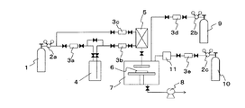
- Example 6 A schematic diagram of the CVD apparatus used in this example is shown in FIG.
- the raw material container 4 is filled with tetrakisdimethylamido hafnium ⁇ Hf [N (CH 3 ) 2 ] 4 ⁇ having a zirconium concentration of 0.9 mass ppm produced by the method of Example 1 as a raw material, and the pressure is reduced by the pressure reducing valve 2a.
- the introduced argon gas 1 is introduced into the raw material container 4 through the mass flow controller 3a to feed the filled raw material to the vaporization chamber 5 through the liquid mass flow controller 3b, and before the introduction of the raw material through the mass flow controller 3c. Each is used to purge the inside of the vaporizing chamber 5.
- the raw material introduced into the vaporization chamber 5 is vaporized by heating and introduced into the reaction chamber 7.
- the vacuum pump 8 is connected to the reaction chamber 7 in order to reduce the pressure in the vaporizing chamber 5 and the reaction chamber 7.
- Argon gas 9, which is a purge gas used to remove unreacted raw material in the reaction chamber 7, is connected to the decompression valve 2b so as to be introduced into the reaction chamber 7 through the mass flow controller 3d.
- the oxygen gas 10 is depressurized by the pressure reducing valve 2c and is connected so that ozone generated by being introduced into the ozone generator 11 through the mass flow controller 3e can be introduced into the reaction chamber 7 as a reactive gas.
- the reaction chamber 7 includes a heating unit that can heat the Si substrate 6 in the chamber to a predetermined temperature.
- the zirconium concentration of the obtained hafnium-containing oxide film was measured using an ICP-MS apparatus (manufactured by Agilent Technologies, 7500cs type).
- Reactive gas ozone, reaction temperature (substrate temperature): 200 ° C
- Reactive gas ozone, reaction temperature (substrate temperature): 200 ° C
- a series of steps A ⁇ B ⁇ C ⁇ D described below was set as one cycle, and after repeating 80 cycles, annealing was performed at a reaction temperature (substrate temperature) of 500 ° C.
- Example 7 Formation of Hafnium-Containing Oxide Film
- Zirconium concentration produced by the method of Example 3 is 0.8 mass ppm tetrakisethylmethylamido hafnium ⁇ Hf [N (CH 3 ) (CH 2 CH 3 )] 4 ⁇
- a hafnium-containing oxide film was formed in the same manner as in Example 6 except that the raw material container 4 filled with was used, and the zirconium concentration of the obtained hafnium-containing oxide film was measured with an ICP-MS apparatus. As a result, the zirconium concentration in the hafnium-containing oxide film was 1.6 mass ppm.
- the obtained distillate was a mixture of tetrakisethylmethylamido hafnium and tertiary butoxylithium from 1 HNMR, and the tertiary butoxylithium concentration in the fraction was 21% by mass.
- the obtained distillate was a mixture of tetrakisethylmethylamido hafnium and 2-methyl-2-butoxylithium according to 1 HNMR, and the concentration of 2-methyl-2-butoxylithium in the fraction was 12% by mass.
- the hafnium-containing oxide film was formed in the same manner as in Example 6 except that tetrakismethylethylhafnium ⁇ Hf [N (CH 3 ) (CH 2 CH 3 )] 4 ⁇ having a zirconium concentration of 840 mass ppm was used.
- the zirconium concentration of the obtained hafnium-containing oxide film was measured with an ICP-MS apparatus. As a result, the zirconium concentration in the hafnium-containing oxide film was 1640 mass ppm.
Landscapes
- Chemical & Material Sciences (AREA)
- Organic Chemistry (AREA)
- Chemical Kinetics & Catalysis (AREA)
- Inorganic Chemistry (AREA)
- General Chemical & Material Sciences (AREA)
- Engineering & Computer Science (AREA)
- Materials Engineering (AREA)
- Mechanical Engineering (AREA)
- Metallurgy (AREA)
- Chemical Vapour Deposition (AREA)
- Organic Low-Molecular-Weight Compounds And Preparation Thereof (AREA)
- Inorganic Compounds Of Heavy Metals (AREA)
Abstract
Description

(1)下記化合物No.1の合成
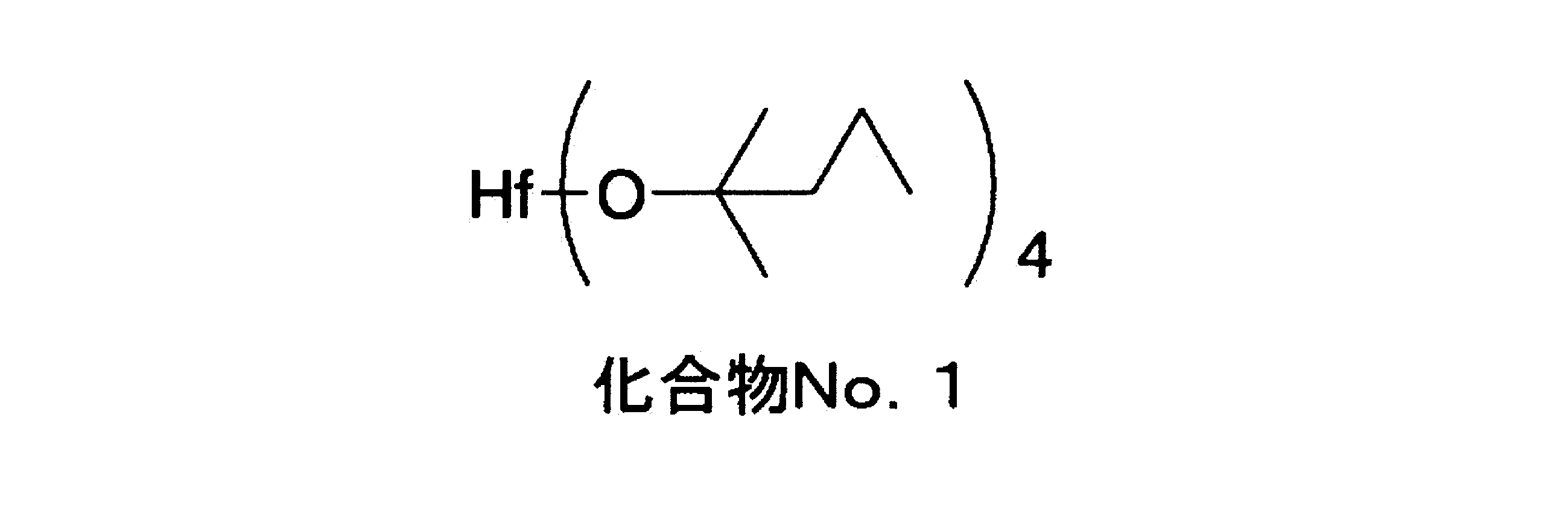

上記(1)の合成で得たジルコニウム濃度が0.6質量ppmの第3級ハフニウムアルコキシド錯体である上記化合物No.1、20.0g(34.3mmol)を滴下漏斗、還流冷却器、温度計及び攪拌機の付いた100mLの5つ口ガラスフラスコに仕込み、このフラスコにリチウムジメチルアミド[LiN(CH3)2]7.7g(151mmol)を添加し、室温で1時間攪拌した。次いでこの反応液を90℃、0.12kPaの条件下蒸留を行い、留分9.2gを得た。得られた留分は、1HNMRより、テトラキスジメチルアミドハフニウム{Hf[N(CH3)2]4}であり、留分中のジルコニウム濃度は0.9質量ppmであり、留分中の2-メチル-2-ペンタノキシリチウム濃度は100質量ppm以下であった(収率76%)。
上記(2)の合成で得たジルコニウム濃度が0.5質量ppmの第3級ハフニウムアルコキシド錯体である上記化合物No.3、20.0g(31.3mmol)を滴下漏斗、還流冷却器、温度計及び攪拌機の付いた100mLの5つ口ガラスフラスコに仕込み、このフラスコにリチウムエチルメチルアミド[LiN(CH3)(CH2CH3)]8.1g(125mmol)を添加し、室温で1時間攪拌した。次いでこの反応液を100℃、0.12kPaの条件下蒸留を行い、留分10.3gを得た。得られた留分は、1HNMRより、テトラキスエチルメチルアミドハフニウム{Hf[N(CH3)(CH2CH3)]4}であり、留分中のジルコニウム濃度は0.8質量ppmであり、留分中の2-メチル-2-ヘキサノキシリチウム濃度は100質量ppm以下であった(収率80%)。
上記(3)の合成で得たジルコニウム濃度が0.5質量ppmの第3級ハフニウムアルコキシド錯体である上記化合物No.8、20.0g(27.8mmol)を滴下漏斗、還流冷却器、温度計及び攪拌機の付いた100mLの5つ口ガラスフラスコに仕込み、このフラスコにリチウムエチルメチルアミド[LiN(CH3)(CH2CH3)]8.0g(122mmol)を添加し、室温で1時間攪拌した。次いでこの反応液を100℃、0.12kPaの条件下蒸留を行い、留分9.4gを得た。得られた留分は、1HNMRより、テトラキスエチルメチルアミドハフニウム{Hf[N(CH3)(CH2CH3)]4}であり、留分中のジルコニウム濃度は0.8質量ppmであり、留分中の2-フェニル-2-プロパノキシリチウム濃度は100質量ppm以下であった(収率82%)。
上記(4)の合成で得たジルコニウム濃度が0.4質量ppmの第3級ハフニウムアルコキシド錯体である上記化合物No.11、20.0g(25.8mmol)を滴下漏斗、還流冷却器、温度計及び攪拌機の付いた100mLの5つ口ガラスフラスコに仕込み、このフラスコにリチウムエチルメチルアミド[LiN(CH3)(CH2CH3)]7.4g(114mmol)を添加し、室温で1時間攪拌した。次いでこの反応液を100℃、0.12kPaの条件下蒸留を行い、留分8.5gを得た。得られた留分は、1HNMRより、テトラキスエチルメチルアミドハフニウム{Hf[N(CH3)(CH2CH3)]4}であり、留分中のジルコニウム濃度は0.8質量ppmであり、留分中のジメチルベンジルカルビノキシリチウム濃度は100質量ppm以下であった(収率80%)。
上記(4)の合成で得たジルコニウム濃度が0.4質量ppmの第3級ハフニウムアルコキシド錯体である上記化合物No.12、20.0g(24.8mmol)を滴下漏斗、還流冷却器、温度計及び攪拌機の付いた100mLの5つ口ガラスフラスコに仕込み、このフラスコにリチウムジエチルアミド[LiN(CH2CH3)2]8.6g(109mmol)を添加し、室温で1時間攪拌した。次いでこの反応液を125℃、0.12kPaの条件下蒸留を行い、留分9.0gを得た。得られた留分は、1HNMRより、テトラキスジエチルアミドハフニウム{Hf[N(CH2CH3)2]4}であり、留分中のジルコニウム濃度は0.7質量ppmであり、留分中の3,7-ジメチル-3-オクタノキシリチウム濃度は100質量ppm以下であった(収率78%)。
本実施例に用いたCVD装置の概略図を図1に示す。
〔方法〕下記A→B→C→Dからなる一連の工程を1サイクルとして、80サイクル繰り返した後、反応温度(基板温度)500℃でアニール処理を実施した。
A.気化室5において気化室温度150℃、気化室圧力2~2.2kPaの条件で気化させたハフニウムアミド錯体の蒸気を反応室7へ導入し、系内の圧力2~2.2kPaで2秒間堆積させる。
B.3秒間のアルゴンパージにより、未反応の原料を除去する。
C.反応性ガスを導入し、系内の圧力1.3kPaで2秒間反応させる
D.3秒間のアルゴンパージにより、未反応の原料を除去する。
その結果、ハフニウム含有酸化膜中のジルコニウム濃度は1.5質量ppmであった。
実施例3の方法によって製造したジルコニウム濃度が0.8質量ppmテトラキスエチルメチルアミドハフニウム{Hf[N(CH3)(CH2CH3)]4}を充填した原料容器4を用いた以外は、上記実施例6と同様な方法でハフニウム含有酸化膜の成膜を行い、得られたハフニウム含有酸化膜のジルコニウム濃度をICP-MS装置で測定した。その結果、ハフニウム含有酸化膜中のジルコニウム濃度は1.6質量ppmであった。
第3級ハフニウムアルコキシド錯体である上記化合物No.3に代えて、第1級ハフニウムアルコキシド錯体であるジルコニウム濃度が0.9質量ppmのテトラエトキシハフニウム[Hf(OCH2CH3)4]を11.2g(31.3mmol)用いた以外は、実施例2と同様な方法で行ったが、蒸留物は得られなかった。
第3級ハフニウムアルコキシドである上記化合物錯体No.3に代えて、第2級ハフニウムアルコキシド錯体であるジルコニウム濃度が0.8質量ppmのテトライソプロポキシハフニウム{Hf[OCH(CH3)2]4}12.9g(31.3mmol)を用いた以外は、実施例2と同様な方法で行ったが、蒸留物は得られなかった。
第3級ハフニウムアルコキシド錯体である上記化合物No.3に代えて、第3級ハフニウムアルコキシド錯体であるジルコニウム濃度が0.7質量ppmのテトラターシャリーブトキシハフニウム{Hf[OC(CH3)3]4}を用い14.7g(31.3mmol)用いた以外は、実施例2と同様な方法で、テトラキスエチルメチルアミドハフニウムの製造を行い、留分12.3gを得た。得られた蒸留分は1HNMRからテトラキスエチルメチルアミドハフニウムとターシャリーブトキシリチウムの混合物であり、留分中のターシャリーブトキシリチウム濃度は21質量%であった。
第3級ハフニウムアルコキシド錯体である上記化合物No.3に代えて、第3級ハフニウムアルコキシド錯体であるジルコニウム濃度が0.7質量ppmのテトラ(2-メチル-2-ブトキシ)ハフニウム{Hf[OC(CH3)2(CH2CH3)]4}を用い16.5g(31.3mmol)用いた以外は、実施例2と同様な方法で、テトラキスエチルメチルアミドハフニウムの製造を行い、留分11.6gを得た。得られた蒸留分は1HNMRからテトラキスエチルメチルアミドハフニウムと2-メチル-2-ブトキシリチウムの混合物であり、留分中の2-メチル-2-ブトキシリチウム濃度は12質量%であった。
3Lの5つ口ガラスフラスコに還流冷却器、温度計、滴下漏斗及び攪拌機を取り付け、内部を窒素置換した。このフラスコにジルコニウム濃度が950質量ppmである四塩化ハフニウム(HfCl4)160gとヘキサン0.4Lを仕込んだ。反応釜を氷冷した後、別途n-ブチルリチウムとエチルメチルアミンから調製したリチウムエチルメチルアミド[LiN(CH3)(CH2CH3)]溶液を滴下漏斗より3時間かけて滴下した。更に、氷冷温度下1時間攪拌を行った後、110℃、0.12kPaで減圧蒸留を行うことにより、留分143gを得た。得られた留分は、1HNMRより、テトラキスエチルメチルアミドハフニウム{Hf[N(CH3)(CH2CH3)]4}であり、留分中のジルコニウム濃度は840質量ppmであった(収率=75%)。
2a、2b、2c:減圧弁
3a、3c、3d、3e、:マスフローコントローラー
3b:液体用マスフローコントローラー
4:原料容器
5:気化室
6:Si基板
7:反応室
8:真空ポンプ
10:酸素ガス
11:オゾン発生器
Claims (2)
- 一般式:Hf[O(CR1R2R3)]4で示される第3級ハフニウムアルコキシド錯体に、一般式:Li(NR4R5)で示されるリチウムアルキルアミドを添加し反応させた後、減圧蒸留を行うことを特徴とする、一般式:Hf(NR4R5)4で示されるハフニウムアミド錯体の製造方法。
(式中において、R1、R2、R3はそれぞれ独立で、フェニル基、ベンジル基、炭素数1~6の1級又は2級又は3級のアルキル基のいずれか一つを表し、R4、R5はそれぞれ独立で、メチル基又はエチル基のいずれか一つを表わす。但し、R1、R2、R3が全てメチル基の場合及びR1、R2、R3のいずれか一つがエチル基で他の二つがメチル基の場合は除く。) - 請求項1記載の方法で製造したハフニウムアミド錯体をハフニウム源として用い、化学的気相成長法により製造することを特徴とするハフニウム含有酸化膜。
Priority Applications (2)
| Application Number | Priority Date | Filing Date | Title |
|---|---|---|---|
| KR1020117014351A KR101319503B1 (ko) | 2008-12-02 | 2009-11-11 | 하프늄아미드 착체의 제조 방법 및 하프늄 함유 산화막 |
| US13/129,490 US8680308B2 (en) | 2008-12-02 | 2009-11-11 | Hafnium amide complex manufacturing method and hafnium-containing oxide film |
Applications Claiming Priority (2)
| Application Number | Priority Date | Filing Date | Title |
|---|---|---|---|
| JP2008-307841 | 2008-12-02 | ||
| JP2008307841A JP5401950B2 (ja) | 2008-12-02 | 2008-12-02 | ハフニウムアミド錯体の製造方法及びハフニウム含有酸化膜 |
Publications (1)
| Publication Number | Publication Date |
|---|---|
| WO2010064524A1 true WO2010064524A1 (ja) | 2010-06-10 |
Family
ID=42233177
Family Applications (1)
| Application Number | Title | Priority Date | Filing Date |
|---|---|---|---|
| PCT/JP2009/069157 Ceased WO2010064524A1 (ja) | 2008-12-02 | 2009-11-11 | ハフニウムアミド錯体の製造方法及びハフニウム含有酸化膜 |
Country Status (4)
| Country | Link |
|---|---|
| US (1) | US8680308B2 (ja) |
| JP (1) | JP5401950B2 (ja) |
| KR (1) | KR101319503B1 (ja) |
| WO (1) | WO2010064524A1 (ja) |
Families Citing this family (4)
| Publication number | Priority date | Publication date | Assignee | Title |
|---|---|---|---|---|
| JP6534570B2 (ja) * | 2015-07-09 | 2019-06-26 | 東京理化器械株式会社 | 反応装置 |
| KR20190005741A (ko) | 2017-07-07 | 2019-01-16 | 도쿄엘렉트론가부시키가이샤 | 반도체 장치의 제조 방법 및 금속 산화물 막의 형성 방법 |
| KR20250143078A (ko) * | 2023-02-03 | 2025-09-30 | 미쓰이금속광업주식회사 | 하프늄산 화합물 함유물 및 그 제조 방법 |
| CN120590428B (zh) * | 2025-08-04 | 2025-10-24 | 合肥安德科铭半导体科技有限公司 | 一种四(二甲胺基)铪的制备方法 |
Citations (6)
| Publication number | Priority date | Publication date | Assignee | Title |
|---|---|---|---|---|
| JP2005263771A (ja) * | 2004-02-18 | 2005-09-29 | Shinko Kagaku Kogyo Kk | 高純度テトラキス(ジアルキルアミノ)ハフニウムの製造法 |
| JP2005298467A (ja) * | 2004-04-12 | 2005-10-27 | Kojundo Chem Lab Co Ltd | 高純度テトラキスジメチルアミノハフニウムとその製造方法およびそれを用いたゲート絶縁膜の製造方法。 |
| JP2005314785A (ja) * | 2003-09-19 | 2005-11-10 | Mitsubishi Materials Corp | ハフニウム含有膜形成材料及び該材料から作製されたハフニウム含有薄膜の製造方法 |
| JP2007051042A (ja) * | 2005-08-19 | 2007-03-01 | Tri Chemical Laboratory Inc | ハフニウム化合物の製造方法、Zr不純物が50ppm以下のハフニウム化合物、及びハフニウム系膜の成膜方法 |
| JP2008189550A (ja) * | 2006-02-20 | 2008-08-21 | Central Glass Co Ltd | ハフニウムアミド錯体の製造方法 |
| US20090005584A1 (en) * | 2007-06-26 | 2009-01-01 | Central Glass Company, Limited | Processes for Producing Hafnium Complexes |
Family Cites Families (3)
| Publication number | Priority date | Publication date | Assignee | Title |
|---|---|---|---|---|
| US6486080B2 (en) * | 2000-11-30 | 2002-11-26 | Chartered Semiconductor Manufacturing Ltd. | Method to form zirconium oxide and hafnium oxide for high dielectric constant materials |
| US20050214458A1 (en) * | 2004-03-01 | 2005-09-29 | Meiere Scott H | Low zirconium hafnium halide compositions |
| US7956207B2 (en) * | 2006-09-28 | 2011-06-07 | Praxair Technology, Inc. | Heteroleptic organometallic compounds |
-
2008
- 2008-12-02 JP JP2008307841A patent/JP5401950B2/ja not_active Expired - Fee Related
-
2009
- 2009-11-11 KR KR1020117014351A patent/KR101319503B1/ko not_active Expired - Fee Related
- 2009-11-11 US US13/129,490 patent/US8680308B2/en not_active Expired - Fee Related
- 2009-11-11 WO PCT/JP2009/069157 patent/WO2010064524A1/ja not_active Ceased
Patent Citations (6)
| Publication number | Priority date | Publication date | Assignee | Title |
|---|---|---|---|---|
| JP2005314785A (ja) * | 2003-09-19 | 2005-11-10 | Mitsubishi Materials Corp | ハフニウム含有膜形成材料及び該材料から作製されたハフニウム含有薄膜の製造方法 |
| JP2005263771A (ja) * | 2004-02-18 | 2005-09-29 | Shinko Kagaku Kogyo Kk | 高純度テトラキス(ジアルキルアミノ)ハフニウムの製造法 |
| JP2005298467A (ja) * | 2004-04-12 | 2005-10-27 | Kojundo Chem Lab Co Ltd | 高純度テトラキスジメチルアミノハフニウムとその製造方法およびそれを用いたゲート絶縁膜の製造方法。 |
| JP2007051042A (ja) * | 2005-08-19 | 2007-03-01 | Tri Chemical Laboratory Inc | ハフニウム化合物の製造方法、Zr不純物が50ppm以下のハフニウム化合物、及びハフニウム系膜の成膜方法 |
| JP2008189550A (ja) * | 2006-02-20 | 2008-08-21 | Central Glass Co Ltd | ハフニウムアミド錯体の製造方法 |
| US20090005584A1 (en) * | 2007-06-26 | 2009-01-01 | Central Glass Company, Limited | Processes for Producing Hafnium Complexes |
Also Published As
| Publication number | Publication date |
|---|---|
| JP2010132577A (ja) | 2010-06-17 |
| JP5401950B2 (ja) | 2014-01-29 |
| KR20110087334A (ko) | 2011-08-02 |
| KR101319503B1 (ko) | 2013-10-17 |
| US8680308B2 (en) | 2014-03-25 |
| US20110230671A1 (en) | 2011-09-22 |
Similar Documents
| Publication | Publication Date | Title |
|---|---|---|
| KR102215341B1 (ko) | 금속 전구체 및 이를 이용하여 제조된 금속 함유 박막 | |
| US9828402B2 (en) | Film-forming composition and method for fabricating film by using the same | |
| TWI510495B (zh) | 具有優良階梯覆蓋性之釕化合物以及藉由沈積該具有優良階梯覆蓋性之釕化合物所形成之薄膜 | |
| JP5816235B2 (ja) | Cvd前駆体 | |
| US11958874B2 (en) | Organo tin compound for thin film deposition and method for forming tin-containing thin film using same | |
| US20170117142A1 (en) | Organic Germanium Amine Compound and Method for Depositing Thin Film Using the Same | |
| KR20130049020A (ko) | 탄탈륨 전구체 화합물 및 이의 제조방법 | |
| JP5401950B2 (ja) | ハフニウムアミド錯体の製造方法及びハフニウム含有酸化膜 | |
| JP2017505858A (ja) | 無機薄膜の生成方法 | |
| JP7637705B2 (ja) | 薄膜形成用プリカーサ、その製造方法、及びそれを含む薄膜製造方法 | |
| KR102093226B1 (ko) | 규소함유 유기 금속 전구체 화합물, 이의 제조방법 및 이를 이용한 금속-규소 산화물 박막의 제조 방법 | |
| CN115279940B (zh) | 铝前体化合物、其制备方法和使用其形成含铝膜的方法 | |
| CN117897518B (zh) | 包含含有第四族金属元素的前体化合物的膜沉积组合物及使用其形成膜的方法 | |
| KR102862617B1 (ko) | 3족 금속 전구체 및 금속 함유 박막 | |
| JP5088232B2 (ja) | ハフニウム錯体の製造方法 | |
| TW202225173A (zh) | 稀土前驅體、製備其的方法和使用其形成薄膜的方法 | |
| CN119798338B (zh) | 一种金属配合物及其制备方法与应用、氧化锆膜 | |
| JP5919882B2 (ja) | コバルト化合物の混合物、及び当該コバルト化合物の混合物を用いたコバルト含有薄膜の製造方法 | |
| JP5842687B2 (ja) | コバルト膜形成用原料及び当該原料を用いたコバルト含有薄膜の製造方法 | |
| US12359317B2 (en) | Rare earth precursor, method of preparing the same, and method of forming thin film using the same | |
| TW202311273A (zh) | 矽前驅物 | |
| KR20230132961A (ko) | 박막 증착을 위한 유기 주석 화합물 및 이를 이용한 주석 함유 박막의 형성 방법 | |
| TWI275657B (en) | Improved precursors for chemical vapour deposition | |
| JP2005126334A (ja) | 有機金属化合物及び該化合物を含む溶液原料並びに金属酸化膜薄膜 | |
| JP2005060358A (ja) | ビスマスアルコキシドとその製造方法およびそれを用いたBi層状強誘電体薄膜の製造方法。 |
Legal Events
| Date | Code | Title | Description |
|---|---|---|---|
| 121 | Ep: the epo has been informed by wipo that ep was designated in this application |
Ref document number: 09830291 Country of ref document: EP Kind code of ref document: A1 |
|
| WWE | Wipo information: entry into national phase |
Ref document number: 13129490 Country of ref document: US |
|
| NENP | Non-entry into the national phase |
Ref country code: DE |
|
| ENP | Entry into the national phase |
Ref document number: 20117014351 Country of ref document: KR Kind code of ref document: A |
|
| 122 | Ep: pct application non-entry in european phase |
Ref document number: 09830291 Country of ref document: EP Kind code of ref document: A1 |