WO2010061829A1 - 可変動弁機構 - Google Patents
可変動弁機構 Download PDFInfo
- Publication number
- WO2010061829A1 WO2010061829A1 PCT/JP2009/069819 JP2009069819W WO2010061829A1 WO 2010061829 A1 WO2010061829 A1 WO 2010061829A1 JP 2009069819 W JP2009069819 W JP 2009069819W WO 2010061829 A1 WO2010061829 A1 WO 2010061829A1
- Authority
- WO
- WIPO (PCT)
- Prior art keywords
- control
- variable
- shaft
- valve
- axis
- Prior art date
- Legal status (The legal status is an assumption and is not a legal conclusion. Google has not performed a legal analysis and makes no representation as to the accuracy of the status listed.)
- Ceased
Links
Images



Classifications
-
- F—MECHANICAL ENGINEERING; LIGHTING; HEATING; WEAPONS; BLASTING
- F01—MACHINES OR ENGINES IN GENERAL; ENGINE PLANTS IN GENERAL; STEAM ENGINES
- F01L—CYCLICALLY OPERATING VALVES FOR MACHINES OR ENGINES
- F01L1/00—Valve-gear or valve arrangements, e.g. lift-valve gear
- F01L1/12—Transmitting gear between valve drive and valve
- F01L1/18—Rocking arms or levers
-
- F—MECHANICAL ENGINEERING; LIGHTING; HEATING; WEAPONS; BLASTING
- F01—MACHINES OR ENGINES IN GENERAL; ENGINE PLANTS IN GENERAL; STEAM ENGINES
- F01L—CYCLICALLY OPERATING VALVES FOR MACHINES OR ENGINES
- F01L13/00—Modifications of valve-gear to facilitate reversing, braking, starting, changing compression ratio, or other specific operations
- F01L13/0015—Modifications of valve-gear to facilitate reversing, braking, starting, changing compression ratio, or other specific operations for optimising engine performances by modifying valve lift according to various working parameters, e.g. rotational speed, load, torque
- F01L13/0021—Modifications of valve-gear to facilitate reversing, braking, starting, changing compression ratio, or other specific operations for optimising engine performances by modifying valve lift according to various working parameters, e.g. rotational speed, load, torque by modification of rocker arm ratio
- F01L13/0026—Modifications of valve-gear to facilitate reversing, braking, starting, changing compression ratio, or other specific operations for optimising engine performances by modifying valve lift according to various working parameters, e.g. rotational speed, load, torque by modification of rocker arm ratio by means of an eccentric
-
- F—MECHANICAL ENGINEERING; LIGHTING; HEATING; WEAPONS; BLASTING
- F01—MACHINES OR ENGINES IN GENERAL; ENGINE PLANTS IN GENERAL; STEAM ENGINES
- F01L—CYCLICALLY OPERATING VALVES FOR MACHINES OR ENGINES
- F01L13/00—Modifications of valve-gear to facilitate reversing, braking, starting, changing compression ratio, or other specific operations
-
- F—MECHANICAL ENGINEERING; LIGHTING; HEATING; WEAPONS; BLASTING
- F01—MACHINES OR ENGINES IN GENERAL; ENGINE PLANTS IN GENERAL; STEAM ENGINES
- F01L—CYCLICALLY OPERATING VALVES FOR MACHINES OR ENGINES
- F01L1/00—Valve-gear or valve arrangements, e.g. lift-valve gear
- F01L1/12—Transmitting gear between valve drive and valve
- F01L1/18—Rocking arms or levers
- F01L1/185—Overhead end-pivot rocking arms
-
- F—MECHANICAL ENGINEERING; LIGHTING; HEATING; WEAPONS; BLASTING
- F01—MACHINES OR ENGINES IN GENERAL; ENGINE PLANTS IN GENERAL; STEAM ENGINES
- F01L—CYCLICALLY OPERATING VALVES FOR MACHINES OR ENGINES
- F01L1/00—Valve-gear or valve arrangements, e.g. lift-valve gear
- F01L1/20—Adjusting or compensating clearance
- F01L1/22—Adjusting or compensating clearance automatically, e.g. mechanically
- F01L1/24—Adjusting or compensating clearance automatically, e.g. mechanically by fluid means, e.g. hydraulically
- F01L1/2405—Adjusting or compensating clearance automatically, e.g. mechanically by fluid means, e.g. hydraulically by means of a hydraulic adjusting device located between the cylinder head and rocker arm
-
- F—MECHANICAL ENGINEERING; LIGHTING; HEATING; WEAPONS; BLASTING
- F01—MACHINES OR ENGINES IN GENERAL; ENGINE PLANTS IN GENERAL; STEAM ENGINES
- F01L—CYCLICALLY OPERATING VALVES FOR MACHINES OR ENGINES
- F01L13/00—Modifications of valve-gear to facilitate reversing, braking, starting, changing compression ratio, or other specific operations
- F01L13/0015—Modifications of valve-gear to facilitate reversing, braking, starting, changing compression ratio, or other specific operations for optimising engine performances by modifying valve lift according to various working parameters, e.g. rotational speed, load, torque
- F01L13/0063—Modifications of valve-gear to facilitate reversing, braking, starting, changing compression ratio, or other specific operations for optimising engine performances by modifying valve lift according to various working parameters, e.g. rotational speed, load, torque by modification of cam contact point by displacing an intermediate lever or wedge-shaped intermediate element, e.g. Tourtelot
- F01L2013/0068—Modifications of valve-gear to facilitate reversing, braking, starting, changing compression ratio, or other specific operations for optimising engine performances by modifying valve lift according to various working parameters, e.g. rotational speed, load, torque by modification of cam contact point by displacing an intermediate lever or wedge-shaped intermediate element, e.g. Tourtelot with an oscillating cam acting on the valve of the "BMW-Valvetronic" type
-
- F—MECHANICAL ENGINEERING; LIGHTING; HEATING; WEAPONS; BLASTING
- F01—MACHINES OR ENGINES IN GENERAL; ENGINE PLANTS IN GENERAL; STEAM ENGINES
- F01L—CYCLICALLY OPERATING VALVES FOR MACHINES OR ENGINES
- F01L13/00—Modifications of valve-gear to facilitate reversing, braking, starting, changing compression ratio, or other specific operations
- F01L13/0015—Modifications of valve-gear to facilitate reversing, braking, starting, changing compression ratio, or other specific operations for optimising engine performances by modifying valve lift according to various working parameters, e.g. rotational speed, load, torque
- F01L13/0063—Modifications of valve-gear to facilitate reversing, braking, starting, changing compression ratio, or other specific operations for optimising engine performances by modifying valve lift according to various working parameters, e.g. rotational speed, load, torque by modification of cam contact point by displacing an intermediate lever or wedge-shaped intermediate element, e.g. Tourtelot
- F01L2013/0073—Modifications of valve-gear to facilitate reversing, braking, starting, changing compression ratio, or other specific operations for optimising engine performances by modifying valve lift according to various working parameters, e.g. rotational speed, load, torque by modification of cam contact point by displacing an intermediate lever or wedge-shaped intermediate element, e.g. Tourtelot with an oscillating cam acting on the valve of the "Delphi" type
-
- F—MECHANICAL ENGINEERING; LIGHTING; HEATING; WEAPONS; BLASTING
- F01—MACHINES OR ENGINES IN GENERAL; ENGINE PLANTS IN GENERAL; STEAM ENGINES
- F01L—CYCLICALLY OPERATING VALVES FOR MACHINES OR ENGINES
- F01L2305/00—Valve arrangements comprising rollers
Definitions
- the present invention relates to a variable valve mechanism that controls valve characteristics in accordance with the operating state of an internal combustion engine.
- variable valve mechanism 100 of Patent Document 1 shown in FIG. 7 is known as a variable valve mechanism that controls the lift amount, operating angle, and opening / closing timing of a valve according to the operating state of an internal combustion engine.
- the variable valve mechanism 100 includes a camshaft 101 that is rotated by a crankshaft (not shown) of an internal combustion engine, and a valve member 103 that opens and closes a valve 102.
- a drive cam 104 is fixed so as to be integrally rotatable, and a swing cam 106 having a cam surface 105 that engages with the valve operating member 103 is supported so as to be relatively rotatable.
- variable link 109 is swingably supported via an eccentric cam.
- One end of the variable link 109 is connected to the drive cam 104 by a ring-shaped link 110, and the other end of the variable link 109 is connected to the swing cam 106 by a rod-shaped link 111.
- the power of the drive cam 104 is transmitted to the swing cam 106 via the three links 109, 110, and 111, and the swing angle of the variable link 109 is changed by the eccentric cam 108, so that the lift amount and action of the valve 102 are changed.
- the angle is changed according to the operating state of the internal combustion engine. JP 11-324625 A
- variable valve mechanism 100 is provided with the control shaft 107 above the camshaft 101 (in the direction away from the cylinder), the entire variable valve mechanism 100 becomes tall and the overall height of the cylinder head increases. It was.
- the present inventors have developed a variable valve mechanism in which a shaft that supports the variable mechanism and a control shaft are integrated.
- the drive cam is a so-called egg-shaped cam having a base circular portion and a cam nose portion. For this reason, the distance between the control shaft and the drive shaft (inter-axis pitch) could not be made smaller than the height of the cam nose.
- an object of the present invention is to provide a variable valve mechanism that is miniaturized by providing a crank mechanism instead of an egg-shaped cam on an input shaft that is rotationally driven by an internal combustion engine.
- a variable valve mechanism includes an input shaft that is rotationally driven by an internal combustion engine in a variable valve mechanism having a variable mechanism for changing an opening / closing amount of the valve.
- a crank mechanism for converting a rotary motion into a reciprocating motion for opening and closing the valve is provided on the input shaft, and the crank mechanism is connected to the variable mechanism.
- changing the opening / closing amount of the valve is not particularly limited, but switching between a state in which the valve is driven and a state in which the driving is completely stopped, or opening / closing the valve with a relatively large lift amount.
- the case where it switches between a state and the state opened and closed with a comparatively small lift amount etc. can be illustrated.
- the mode of the variable mechanism is not particularly limited. However, since the number of parts can be reduced and the entire variable valve mechanism can be reduced (particularly, the height of the variable valve mechanism can be lowered), the input swing connected to the crank mechanism can be reduced.
- the input rocking member and the output rocking member are: It is preferable that the control shaft is pivotally supported by a control shaft provided in parallel with the input shaft, and the control member is provided on the control shaft.
- the relative phase between the input rocking member and the output rocking member is displaced by changing the distance between the center of the supporting portion and the axis of the control shaft.
- the mode of the displacement member is not particularly limited, but a ring arm including a ring part that is rotatably fitted to the control member and an arm part that extends from the ring part, or is rotatably supported by the control member.
- a roller circumscribing can be exemplified.
- the displacement member when the displacement member is a ring arm, the displacement member can follow the rotation of the control member without providing a lost motion mechanism.
- the displacement member is a roller, friction with the control member is reduced.
- control member is not particularly limited, but it is preferable to have an outer peripheral surface whose distance from the axis of the control shaft gradually changes, and as a specific aspect, the control member is deviated from the axis of the control shaft.
- a cylindrical control cam etc. can be illustrated.
- valve operating member between the output swing member and the valve.
- the mode of the valve operating member is not particularly limited, and examples thereof include a rocker arm that swings with a base end as a fulcrum, a valve lifter that can move linearly in the axial direction of the valve, and the like.
- variable valve mechanism that is reduced in size by providing a crank mechanism instead of an egg-shaped cam on an input shaft that is rotationally driven by an internal combustion engine.
- the variable valve mechanism 10 having a variable mechanism 30 for changing the opening / closing amount of the valve 13 includes an input shaft 12 that is rotationally driven by an internal combustion engine, and a reciprocating motion for opening and closing the valve 13 by rotating the input shaft 12.
- a crank mechanism 14 for converting to a crankshaft is provided on the input shaft 12, and the crank mechanism 14 is connected to a variable mechanism 30.
- the variable mechanism 30 includes an input swing member 35 coupled to the crank mechanism 14, an output swing member 40 that presses the valve 13, and a relative phase between the input swing member 35 and the output swing member 40 by rotation. And a control member 31 for displacing.
- the input rocking member 35 and the output rocking member 40 are pivotally supported by a control shaft 25 provided in parallel with the input shaft 12.
- the control member 31 is provided on the control shaft 25 and has an outer peripheral surface 32 in which the distance from the axis 26 of the control shaft 25 gradually changes.
- the variable mechanism 30 includes a displacement member 49 that is connected to the input swing member 35 and the output swing member 40 via connection members 46 and 47 and is displaced by the rotation of the control member 31.
- the displacement member 49 is a ring arm 49 including a ring portion 49 a that is rotatably fitted to the control member 31, and an arm portion 49 b that extends from the ring portion 49 a.
- the control member 31 is a cylindrical shape that is biased from the axis 26. This is a control cam 31.
- variable valve mechanism 10 of this embodiment is used in an intake system of an automobile gasoline engine. However, the same mechanism can be applied to the exhaust system of a gasoline engine. As shown in FIGS. 1 to 3, the input shaft 12 of the variable valve mechanism 10 is supported by a housing (not shown) above the cylinder head 11 (in the direction away from the cylinder, the same applies hereinafter), It is rotationally driven by the shaft.
- a crank mechanism 14 is provided at a position corresponding to the valve 13 in the middle of the input shaft 12.
- the crank mechanism 14 is fixed to the input shaft 12 and includes a substantially cylindrical crank pin 15 that is offset from an axis 18 thereof, and a crank rod 16 that has a ring 17 that is rotatably fitted on the crank pin 15 at the base end. It has become.
- a rocker arm 21 that automatically adjusts the valve clearance is supported by a pivot 22 on the base end side so as to be swingable up and down, and a spring on the valve 13 (Not shown) is biased upward.
- a pressure surface 23 for pressing the valve 13 is provided at the tip of the rocker arm 21, and a base roller 24 is rotatably supported at an intermediate portion of the rocker arm 21.
- control shaft 25 is provided in parallel with the input shaft 12 so that the height of the shaft center 26 is substantially the same as the height of the shaft center 18 of the input shaft 12. Is connected to an actuator (not shown) that is controlled according to the operating state of the engine and rotates the control shaft 25.
- the control shaft 25 is provided with a variable mechanism 30.
- the variable mechanism 30 includes a control cam 31 formed on the control shaft 25, a cam arm 40 pivotally supported by the control shaft 25 on the side of the control cam 31 in the axial direction of the control shaft 25, A main arm 35 pivotally supported by the control shaft 25 on the side of the cam arm 40 that is the axial direction of the control shaft 25 (the side opposite to the control cam 31), and the main arm 35 are a first connecting member. 46 and a ring arm 49 connected to the cam arm 40 via a second connecting member 47.
- the control cam 31 is a so-called eccentric cam deviated from the axis 26 of the control shaft 25, and the outer circumferential surface (cam surface) 32 has a gradually changing distance from the axis 26 of the control shaft 25. It has become. Further, the control cam 31 is fixed to the control shaft 25, and the control cam 31 is rotated by the rotation of the control shaft 25.
- the control shaft 25 is inserted in an intermediate portion, and a second connecting member 47 is pivotally attached to an upper end by a member 51 so as to be swingable.
- the lower surface is a cam surface 41 that contacts the base roller 24 and presses the valve 13 via the rocker arm 21.
- the cam surface 41 includes an arcuate curved base surface portion 44 centering on the axis 26 of the control shaft 25, and a concave curved lift surface portion 45 continuing from the base surface portion 44.
- the main arm 35 has a control shaft 25 inserted in an intermediate portion thereof, and a first connecting member 46 is pivotally attached to one end by a member 52 so as to be swingable. At the other end, the tip end of the crank rod 16 is pivotally attached by a member 53 so as to be swingable.
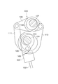
- the ring arm 49 includes a ring portion 49a that is rotatably fitted to the control cam 31, and an arm portion 49b that extends from the ring portion 49a.
- the tip of the arm portion 49b is pivotally attached to the first connecting member 46 and the second connecting member 47 by a connecting pin 50 so as to be swingable.
- variable mechanism 30 configured as described above is in a state in which each member is connected so as to be swingable.
- variable valve mechanism 10 The operation of the variable valve mechanism 10 will be described with reference to FIGS.
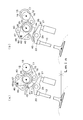
- FIG. 4 shows the relative phase displacement between the main arm 35 and the cam arm 40 due to the rotation of the control cam 31.
- both a and b of FIG. 4 are cases where the tip of the crank rod 16 is farthest from the axis 18 of the input shaft 12.
- 4A shows a state in which the axis 48 of the connecting pin 50 is closest to the axis 26 of the control shaft 25, that is, the distance between the axis 48 of the connecting pin 50 and the axis 26 of the control shaft 25 is as follows.
- 4b shows the state in which the axis 48 of the connecting pin 50 is farthest from the axis 26 of the control shaft 25, that is, the axis 48 of the connecting pin 50 and the axis 26 of the control shaft 25.
- the ring arm 49, the 1st connection member 46, and the 2nd connection member 47 are shown with the broken line, and the crank rod 16 is shown with the dashed-two dotted line.
- the ring cam 49 is continuously displaced as the control cam 31 is rotated as the control shaft 25 is rotated.
- the distance between the axis 48 of the connecting pin 50 and the axis 26 of the control shaft 25 is continuously changed.
- the cam arm 40 that pivotally supports the second connecting member 47 supported by the connecting pin 50. Oscillates around the control shaft 25, and the contact position on the cam surface 41 with the base roller 24 changes. Specifically, when the shaft center 48 of the connecting pin 50 is closest to the shaft center 26 of the control shaft 25, the cam arm 40 is located in the base surface portion 44 away from the lift surface portion 45 as shown in FIG. It contacts the base roller 24 at the position. On the other hand, when the shaft center 48 of the connecting pin 50 is farthest from the shaft center 26 of the control shaft 25, the cam arm 40 is located at the base surface portion 44 near the lift surface portion 45 as shown in FIG. It contacts the roller 24.
- the cam arm 40 becomes lifted. In contact with the base roller 24 at a position within the base surface portion 44 closer to the surface portion 45, conversely, the shorter the distance between the shaft center 48 of the connecting pin 50 and the shaft center 26 of the control shaft 25, that is, the shaft of the connecting pin 50 As the center 48 approaches the axis 26 of the control shaft 25, the cam arm 40 comes into contact with the base roller 24 at a position in the base surface portion 44 that is further away from the lift surface portion 45.
- the main arm 35 pivotally supports the first coupling member 46 pivotally supported by the coupling pin 50 at one end so as to be swingable, but the other end is coupled to the tip of the crank rod 16. If the position of the tip of the crank rod 16 does not change, the main arm 35 does not swing. Therefore, the relative phase between the main arm 35 and the cam arm 40 is continuously displaced by continuously changing the distance between the axis 48 of the connecting pin 50 and the axis 26 of the control shaft 25.
- FIG. 5 shows the operation of the variable valve mechanism 10 when the valve 13 is opened and closed with the minimum lift amount.
- the state of the control cam 31 in FIGS. 5a and 5b is the state where the lift amount when the valve 13 is lifted to the maximum, that is, when the valve 13 is pushed down most (the state of FIG. 5b).
- the distance between the axis 48 of the connecting pin 50 and the axis 26 of the control shaft 25 is the shortest.
- the crank pin 15 rotates around the axis 18 of the input shaft 12 as the input shaft 12 rotates. Due to the rotation of the crank pin 15, the crank rod 16 in which the base end ring 17 is rotatably fitted to the crank pin 15 is displaced, and the distance between the distal end of the crank rod 16 and the axis 18 of the input shaft 12. Changes. However, since the tip end of the crank rod 16 is pivotally attached to the tip end of the main arm 35, the displacement of the tip end of the crank rod 16 (particularly the axis center of the axis attached by the main arm) is the axis of the control shaft 25. The displacement is a certain length on an arc centered at 26.
- the rotation of the input shaft 12 causes the tip of the crank rod 16 to reciprocate a certain length on the arc, so that the rotational movement of the input shaft 12 acts on the main arm 35 (eventually opens and closes the valve 13). Is converted into reciprocating motion.
- the main arm 35 swings.
- the ring arm 49 connected to the main arm 35 via the first connecting member 46 swings around the control cam 31.
- the cam arm 40 connected to the ring arm 49 via the second connecting member 47 swings.
- the cam arm 40 swings, the base roller 24 slides within the cam surface 41. While the base roller 24 is in contact with the base surface portion 44, the rocker arm 21 does not generate a force to push down the valve 13 against the urging force of the spring, and the valve 13 is held in the closed position.
- the rocker arm 21 comes into contact with the lift surface 45, the rocker arm 21 is pushed down by the cam arm 40. Thereby, the pressing surface 23 pushes down the valve 13 against the urging force of the spring.
- FIG. 6 shows the operation of the variable valve mechanism 10 when the valve 13 is opened and closed with the maximum lift amount.
- the state of the control cam 31 of FIGS. 6a and 6b is the state where the lift amount when the valve 13 is lifted to the maximum, that is, when the valve 13 is pushed down most (the state of FIG. 6b).
- the distance between the axis 48 of the connecting pin 50 and the axis 26 of the control shaft 25 is the longest.
- the following effects (a) to (e) can be obtained.
- (A) By using the crank mechanism 14 instead of the egg-shaped cam, the distance (inter-axis pitch) between the control shaft 25 and the input shaft 12 can be reduced, and the variable valve mechanism can be reduced in size.
- the egg-shaped cam can only act to press the part where the variable mechanism abuts, but the crank mechanism has the action of pressing the part where the variable mechanism is connected and the action of pulling. This can be performed alternately, and the part of the variable mechanism can be displaced more greatly.
- (B) By using the crank mechanism 14 instead of the egg-shaped cam, the lost motion mechanism for contacting the variable mechanism with the egg-shaped cam can be eliminated.
- variable mechanism 30 Since the variable mechanism 30 is supported by the control shaft 25, the overall height of the cylinder head can be made lower than the continuous variable valve mechanism (for example, the variable valve mechanism 100) of other rotation control systems.
- the variable valve mechanism can be reduced in size.
- D By using a so-called link mechanism in which each member of the variable mechanism 30 is connected, the lost motion mechanism for following the control cam can be eliminated.
- E By providing a variable valve mechanism for each valve 13 (single valve complete), it is mounted on an internal combustion engine without being affected by plug tubes provided in the upper central part of the cylinder and peripheral components such as injectors. it can.
- this invention is not limited to the said Example, It can implement in the range which does not deviate from the meaning of invention.
- a mode in which the displacement member is a member in contact with the control cam and the ring arm is eliminated can be used.
- variable valve mechanism 1 is an overall view of a variable valve mechanism of the present invention. It is a perspective view of the variable mechanism of the variable valve mechanism. It is a disassembled perspective view of the variable mechanism of the variable valve mechanism. It is explanatory drawing of the displacement of the cam arm by rotation of the control cam of the variable valve mechanism. It is explanatory drawing when the valve lift amount in the same variable valve mechanism is minimized. It is explanatory drawing when maximizing the valve lift amount in the variable valve mechanism. It is a general view of the conventional variable valve mechanism.
Landscapes
- Engineering & Computer Science (AREA)
- Mechanical Engineering (AREA)
- General Engineering & Computer Science (AREA)
- Valve Device For Special Equipments (AREA)
Abstract
Description
この可変動弁機構100は、内燃機関のクランク軸(図示略)によって回転されるカムシャフト101と、バルブ102を開閉する動弁部材103とを備えている。カムシャフト101上には、駆動カム104が一体回動可能に固定されるとともに、動弁部材103に係合するカム面105を備えた揺動カム106が相対回動可能に支持されている。
また、カムシャフト101と平行なコントロールシャフト107上には、偏心カム108を介して可変リンク109が揺動可能に支持されている。可変リンク109の一端はリング状リンク110で駆動カム104に連結され、可変リンク109の他端がロッド状リンク111で揺動カム106に連結されている。そして、駆動カム104の動力を三本のリンク109,110,111を介して揺動カム106に伝え、可変リンク109の揺動角度を偏心カム108で変化させて、バルブ102のリフト量及び作用角を内燃機関の運転状態に応じて変更するようになっている。
動弁部材の態様としては、特に限定はされないが、基端を支点に揺動するロッカアームや、バルブの軸線方向へ直線移動可能なバルブリフタ等が例示できる。
可変機構30は、クランク機構14に連結されている入力揺動部材35と、バルブ13を押圧する出力揺動部材40と、回動により入力揺動部材35と出力揺動部材40との相対位相を変位させるコントロール部材31とを有している。入力揺動部材35と出力揺動部材40は、インプットシャフト12と平行に設けられたコントロールシャフト25に揺動可能に軸支されている。コントロール部材31は、コントロールシャフト25に設けられ、コントロールシャフト25の軸心26からの距離が漸次変化する外周面32を有している。可変機構30は、入力揺動部材35及び出力揺動部材40に連結部材46、47を介して連結され、コントロール部材31の回動により変位する変位部材49を有している。
変位部材49から突出して二つの連結部材46、47を揺動可能に支持している支持部50の中心48と、軸心26との距離が変化することにより、入力揺動部材35と出力揺動部材40との相対位相が変位する。
変位部材49は、コントロール部材31に回転自在に外嵌するリング部49aと、リング部49aから伸びるアーム部49bとからなるリングアーム49であり、コントロール部材31は、軸心26から偏倚した円柱状のコントロールカム31である。
カム面41は、コントロールシャフト25の軸心26を中心とする弧状曲面のベース面部44と、ベース面部44から連続し、凹曲面状のリフト面部45とからなっている。
図4のa、bに示すように、コントロールシャフト25の回動に伴いコントロールカム31が回動することにより、リングアーム49が連続的に変位する。リングアーム49が連続的に変位することにより、連結ピン50の軸心48とコントロールシャフト25の軸心26との距離が連続的に変化する。
具体的には、連結ピン50の軸心48がコントロールシャフト25の軸心26に最も近づいている場合には、図4aに示すように、カムアーム40は、リフト面部45から離れたベース面部44内の位置でベースローラ24と当接する。一方、連結ピン50の軸心48がコントロールシャフト25の軸心26から最も離れている場合には、図4bに示すように、カムアーム40は、リフト面部45に近いベース面部44内の位置でベースローラ24と当接する。
従って、連結ピン50の軸心48とコントロールシャフト25の軸心26との距離が長くなるほど、すなわち、連結ピン50の軸心48がコントロールシャフト25の軸心26から離れるほど、カムアーム40は、リフト面部45により近いベース面部44内の位置でベースローラ24と当接し、逆に、連結ピン50の軸心48とコントロールシャフト25の軸心26との距離が短くなるほど、すなわち、連結ピン50の軸心48がコントロールシャフト25の軸心26に近づくほど、カムアーム40は、リフト面部45からより離れたベース面部44内の位置でベースローラ24と当接する。
(a)卵型カムに代えてクランク機構14を用いたことで、コントロールシャフト25とインプットシャフト12との距離(軸間ピッチ)を小さくすることができ、可変動弁機構を小型化できる。このことを、詳説すると、卵型カムは、可変機構の当接している部位を押圧する作用しかできないが、クランク機構は、可変機構の連結している部位を押圧する作用と牽引する作用とを交互に行うことができ、可変機構の当該部位をより大きく変位することができることによる。
(b)卵型カムに代えてクランク機構14を用いたことで、卵型カムに可変機構が当接するためのロストモーション機構をなくすことができる。
(c)可変機構30がコントロールシャフト25に支持されていることで、他の回転制御系の連続可変動弁機構(例えば、可変動弁機構100)より、シリンダヘッドの全高を低くすることができ、可変動弁機構を小型化できる。
(d)可変機構30の各部材が連結された状態である、いわゆるリンク機構としたことで、コントロールカムに追従するためのロストモーション機構をなくすことができる。
(e)各バルブ13毎に可変動弁機構を設ける(単弁完結とする)ことで、シリンダ上方中央部に設けられるプラグチューブや、インジェクター等の周辺部品からの影響を受けることなく内燃機関に搭載できる。
例えば、変位部材をコントロールカムに接する部材にし、リングアームをなくした態様等があげられる。
12 インプットシャフト
13 バルブ
14 クランク機構
21 ロッカアーム
25 コントロールシャフト
26 コントロールシャフトの軸心
30 可変機構
31 コントロールカム
32 外周面
35 メインアーム
40 カムアーム
41 カム面
46 第一連結部材
47 第二連結部材
48 連結ピンの軸心
49 リングアーム
49a リング部
49b アーム部
50 連結ピン
Claims (5)
- バルブ(13)の開閉量を変更する可変機構(30)を有する可変動弁機構(10)において、
内燃機関により回転駆動されるインプットシャフト(12)を有し、
前記インプットシャフト(12)の回転運動を前記バルブ(13)を開閉するための往復運動に変換するクランク機構(14)が前記インプットシャフト(12)に設けられ、 前記クランク機構(14)が前記可変機構(30)に連結されていることを特徴とする可変動弁機構。 - 前記可変機構(30)は、前記クランク機構(14)に連結されている入力揺動部材(35)と、前記バルブ(13)を押圧する出力揺動部材(40)と、回動により前記入力揺動部材(35)と前記出力揺動部材(40)との相対位相を変位させるコントロール部材(31)とを有し、
前記入力揺動部材(35)及び出力揺動部材(40)は、前記インプットシャフト(12)と平行に設けられたコントロールシャフト(25)に揺動可能に軸支され、
前記コントロール部材(31)は、前記コントロールシャフト(25)に設けられている請求項1記載の可変動弁機構。 - 前記コントロール部材(31)は、前記コントロールシャフト(25)の軸心(26)からの距離が漸次変化する外周面(32)を有し、
前記可変機構(30)は、前記入力揺動部材(35)及び出力揺動部材(40)に連結部材(46、47)を介して連結され、前記コントロール部材(31)の回動により変位する変位部材(49)を有し、
前記変位部材(49)から突出して二つの前記連結部材(46、47)を揺動可能に支持している支持部(50)の中心(48)と、前記軸心(26)との距離が変化することにより、前記入力揺動部材(35)と前記出力揺動部材(40)との相対位相が変位する請求項2記載の可変動弁機構。 - 前記変位部材(49)は、前記コントロール部材(31)に回転自在に外嵌するリング部(49a)と、前記リング部(49a)から伸びるアーム部(49b)とからなるリングアーム(49)である請求項3記載の可変動弁機構。
- 前記コントロール部材(31)は、前記軸心(26)から偏倚した円柱状のコントロールカム(31)である請求項3又は4項記載の可変動弁機構。
Priority Applications (2)
| Application Number | Priority Date | Filing Date | Title |
|---|---|---|---|
| US12/998,495 US8833317B2 (en) | 2008-11-26 | 2009-11-25 | Variable valve mechanism |
| DE112009002660.5T DE112009002660B4 (de) | 2008-11-26 | 2009-11-25 | Variabler Ventilmechnismus |
Applications Claiming Priority (2)
| Application Number | Priority Date | Filing Date | Title |
|---|---|---|---|
| JP2008-301742 | 2008-11-26 | ||
| JP2008301742A JP5313644B2 (ja) | 2008-11-26 | 2008-11-26 | 可変動弁機構 |
Publications (1)
| Publication Number | Publication Date |
|---|---|
| WO2010061829A1 true WO2010061829A1 (ja) | 2010-06-03 |
Family
ID=42225702
Family Applications (1)
| Application Number | Title | Priority Date | Filing Date |
|---|---|---|---|
| PCT/JP2009/069819 Ceased WO2010061829A1 (ja) | 2008-11-26 | 2009-11-25 | 可変動弁機構 |
Country Status (5)
| Country | Link |
|---|---|
| US (1) | US8833317B2 (ja) |
| JP (1) | JP5313644B2 (ja) |
| KR (1) | KR101585490B1 (ja) |
| DE (1) | DE112009002660B4 (ja) |
| WO (1) | WO2010061829A1 (ja) |
Families Citing this family (5)
| Publication number | Priority date | Publication date | Assignee | Title |
|---|---|---|---|---|
| JP5334603B2 (ja) * | 2009-01-23 | 2013-11-06 | 株式会社オティックス | 可変動弁機構 |
| JP5294156B2 (ja) * | 2009-11-12 | 2013-09-18 | スズキ株式会社 | 内燃機関の可変動弁装置 |
| US9133735B2 (en) | 2013-03-15 | 2015-09-15 | Kohler Co. | Variable valve timing apparatus and internal combustion engine incorporating the same |
| US9038588B2 (en) | 2013-10-03 | 2015-05-26 | Honda Motor Co., Ltd. | Continuously variable valve lift mechanism |
| CN206889048U (zh) * | 2017-06-09 | 2018-01-16 | 长城汽车股份有限公司 | 配气机构、发动机和车辆 |
Citations (3)
| Publication number | Priority date | Publication date | Assignee | Title |
|---|---|---|---|---|
| JPH11324625A (ja) * | 1998-05-19 | 1999-11-26 | Nissan Motor Co Ltd | 内燃機関の可変動弁機構 |
| JP2006329084A (ja) * | 2005-05-26 | 2006-12-07 | Yamaha Motor Co Ltd | エンジンの動弁装置 |
| JP3996751B2 (ja) * | 2000-09-21 | 2007-10-24 | 株式会社日立製作所 | 内燃機関の可変動弁装置 |
Family Cites Families (8)
| Publication number | Priority date | Publication date | Assignee | Title |
|---|---|---|---|---|
| US6568361B2 (en) * | 2000-09-21 | 2003-05-27 | Unisia Jecs Corporation | Valve operating device for internal combustion engines |
| JP4254582B2 (ja) * | 2004-03-12 | 2009-04-15 | 日産自動車株式会社 | 内燃機関のバルブリフト量調整機構および調整方法 |
| JP4289260B2 (ja) * | 2004-08-31 | 2009-07-01 | トヨタ自動車株式会社 | 可変動弁装置 |
| JP2007040291A (ja) * | 2005-06-28 | 2007-02-15 | Hitachi Ltd | 内燃機関の可変動弁装置 |
| JP4409519B2 (ja) * | 2006-02-02 | 2010-02-03 | 日立オートモティブシステムズ株式会社 | 内燃機関の動弁装置 |
| KR100993368B1 (ko) * | 2008-01-22 | 2010-11-09 | 현대자동차주식회사 | 연속 가변 밸브 리프트 장치 |
| KR101063489B1 (ko) * | 2008-11-20 | 2011-09-07 | 현대자동차주식회사 | 가변 밸브 리프트 |
| JP5119233B2 (ja) * | 2009-12-16 | 2013-01-16 | 日立オートモティブシステムズ株式会社 | 内燃機関の可変動弁装置 |
-
2008
- 2008-11-26 JP JP2008301742A patent/JP5313644B2/ja not_active Expired - Fee Related
-
2009
- 2009-11-25 DE DE112009002660.5T patent/DE112009002660B4/de not_active Expired - Fee Related
- 2009-11-25 US US12/998,495 patent/US8833317B2/en not_active Expired - Fee Related
- 2009-11-25 WO PCT/JP2009/069819 patent/WO2010061829A1/ja not_active Ceased
- 2009-11-25 KR KR1020117008741A patent/KR101585490B1/ko not_active Expired - Fee Related
Patent Citations (3)
| Publication number | Priority date | Publication date | Assignee | Title |
|---|---|---|---|---|
| JPH11324625A (ja) * | 1998-05-19 | 1999-11-26 | Nissan Motor Co Ltd | 内燃機関の可変動弁機構 |
| JP3996751B2 (ja) * | 2000-09-21 | 2007-10-24 | 株式会社日立製作所 | 内燃機関の可変動弁装置 |
| JP2006329084A (ja) * | 2005-05-26 | 2006-12-07 | Yamaha Motor Co Ltd | エンジンの動弁装置 |
Also Published As
| Publication number | Publication date |
|---|---|
| US20110197838A1 (en) | 2011-08-18 |
| DE112009002660B4 (de) | 2021-04-01 |
| JP2010127158A (ja) | 2010-06-10 |
| KR20110088507A (ko) | 2011-08-03 |
| KR101585490B1 (ko) | 2016-01-14 |
| DE112009002660T5 (de) | 2012-06-21 |
| JP5313644B2 (ja) | 2013-10-09 |
| US8833317B2 (en) | 2014-09-16 |
Similar Documents
| Publication | Publication Date | Title |
|---|---|---|
| JP5028355B2 (ja) | 可変動弁機構 | |
| JP5313644B2 (ja) | 可変動弁機構 | |
| JP2007170333A (ja) | 可変動弁機構 | |
| JP4103871B2 (ja) | 可変動弁装置 | |
| US7032551B2 (en) | Adjusting mechanism adjusting method of valve-lift amount of internal combustion engine | |
| JP4697011B2 (ja) | 可変動弁機構 | |
| JP4771874B2 (ja) | 可変動弁機構 | |
| JP4289193B2 (ja) | エンジンの可変動弁装置 | |
| CN101550849A (zh) | 可变气门致动器 | |
| JP2006070738A (ja) | 可変動弁装置 | |
| JP4469341B2 (ja) | 可変動弁機構 | |
| JP2005054700A (ja) | 内燃機関におけるデコンプ装置 | |
| JP4200975B2 (ja) | 内燃機関の可変動弁装置 | |
| JP2004239249A (ja) | 内燃機関の動弁機構 | |
| JP2000337115A (ja) | 内燃機関の動弁装置 | |
| JP4507997B2 (ja) | 内燃機関の可変動弁装置 | |
| JP2007077940A (ja) | 可変動弁機構 | |
| KR101080793B1 (ko) | 내연 기관의 밸브 어셈블리의 밸브 개폐 및 밸브 행정 조절장치 및 이를 구비한 내연 기관 | |
| JP4535973B2 (ja) | 可変動弁機構 | |
| JP2004150301A (ja) | 内燃機関の可変動弁装置 | |
| JP2006144743A (ja) | 内燃機関の可変動弁装置 | |
| JP5448332B2 (ja) | 内燃機関の動弁装置 | |
| JP2006283630A (ja) | エンジンの動弁装置 | |
| JP4180012B2 (ja) | 内燃機関の可変動弁装置 | |
| JP4499597B2 (ja) | エンジンの動弁装置 |
Legal Events
| Date | Code | Title | Description |
|---|---|---|---|
| 121 | Ep: the epo has been informed by wipo that ep was designated in this application |
Ref document number: 09829077 Country of ref document: EP Kind code of ref document: A1 |
|
| ENP | Entry into the national phase |
Ref document number: 20117008741 Country of ref document: KR Kind code of ref document: A |
|
| WWE | Wipo information: entry into national phase |
Ref document number: 12998495 Country of ref document: US |
|
| WWE | Wipo information: entry into national phase |
Ref document number: 1120090026605 Country of ref document: DE |
|
| 122 | Ep: pct application non-entry in european phase |
Ref document number: 09829077 Country of ref document: EP Kind code of ref document: A1 |