WO2010061809A1 - 移動型x線装置及び回転陽極制御方法 - Google Patents
移動型x線装置及び回転陽極制御方法 Download PDFInfo
- Publication number
- WO2010061809A1 WO2010061809A1 PCT/JP2009/069780 JP2009069780W WO2010061809A1 WO 2010061809 A1 WO2010061809 A1 WO 2010061809A1 JP 2009069780 W JP2009069780 W JP 2009069780W WO 2010061809 A1 WO2010061809 A1 WO 2010061809A1
- Authority
- WO
- WIPO (PCT)
- Prior art keywords
- ray
- unit
- mobile
- anode
- rotation
- Prior art date
- Legal status (The legal status is an assumption and is not a legal conclusion. Google has not performed a legal analysis and makes no representation as to the accuracy of the status listed.)
- Ceased
Links
Images



Classifications
-
- A—HUMAN NECESSITIES
- A61—MEDICAL OR VETERINARY SCIENCE; HYGIENE
- A61B—DIAGNOSIS; SURGERY; IDENTIFICATION
- A61B6/00—Apparatus or devices for radiation diagnosis; Apparatus or devices for radiation diagnosis combined with radiation therapy equipment
- A61B6/02—Arrangements for diagnosis sequentially in different planes; Stereoscopic radiation diagnosis
- A61B6/03—Computed tomography [CT]
- A61B6/032—Transmission computed tomography [CT]
-
- A—HUMAN NECESSITIES
- A61—MEDICAL OR VETERINARY SCIENCE; HYGIENE
- A61B—DIAGNOSIS; SURGERY; IDENTIFICATION
- A61B6/00—Apparatus or devices for radiation diagnosis; Apparatus or devices for radiation diagnosis combined with radiation therapy equipment
- A61B6/40—Arrangements for generating radiation specially adapted for radiation diagnosis
- A61B6/4021—Arrangements for generating radiation specially adapted for radiation diagnosis involving movement of the focal spot
- A61B6/4028—Arrangements for generating radiation specially adapted for radiation diagnosis involving movement of the focal spot resulting in acquisition of views from substantially different positions, e.g. EBCT
-
- A—HUMAN NECESSITIES
- A61—MEDICAL OR VETERINARY SCIENCE; HYGIENE
- A61B—DIAGNOSIS; SURGERY; IDENTIFICATION
- A61B6/00—Apparatus or devices for radiation diagnosis; Apparatus or devices for radiation diagnosis combined with radiation therapy equipment
- A61B6/44—Constructional features of apparatus for radiation diagnosis
- A61B6/4405—Constructional features of apparatus for radiation diagnosis the apparatus being movable or portable, e.g. handheld or mounted on a trolley
Definitions
- the present invention relates to a mobile X-ray apparatus that moves in a hospital and performs X-ray imaging and a rotary anode control method.
- the mobile X-ray apparatus As a medical X-ray apparatus, there is a mobile X-ray apparatus that moves inside a hospital and performs X-ray imaging.
- the mobile X-ray apparatus is mainly used for X-ray imaging of a patient or an emergency patient who cannot move in a hospital room or an operating room.
- a mobile X-ray device is equipped with a carriage, a main body mounted on the carriage, a rotating anode (rotor), an X-ray tube that irradiates the subject with X-rays, and an X-ray that supplies voltage to the X-ray tube It has a voltage device and a support mechanism that movably supports the X-ray tube on the main body.
- a rotating anode rotor
- an X-ray tube that irradiates the subject with X-rays
- an X-ray that supplies voltage to the X-ray tube It has a voltage device and a support mechanism that movably supports the X-ray tube on the main body.
- the rotation sound of the rotary anode will continue to be generated.
- the rotation sound of the rotating anode disturbs other patients' sleep and the like, which may cause trouble for other patients.
- the rotational speed of the rotating anode is increased in order to improve the heat dissipation of the focal plane of the rotating anode of the X-ray tube.
- the power consumption for braking the rotating anode is required, and the power consumption of the battery (power storage unit) increases.
- the power consumption increases, the battery mounted on the cart of the mobile X-ray apparatus is consumed, and the number of X-ray images is limited. Therefore, frequent charging work is required.
- An object of the present invention is to provide a mobile X-ray apparatus and a rotary anode control method that suppress power consumption of the mobile X-ray apparatus and suppress noise of the rotary anode of the X-ray tube.
- the present invention provides a main body, a carriage on which the main body is mounted, an X-ray generator having an X-ray tube that generates X-rays, and an X-ray that adjusts an irradiation field of the X-rays
- a movable X-ray apparatus comprising a movable diaphragm, an arm that supports the X-ray generation unit and the X-ray movable diaphragm, and a column that is installed on the carriage and supports the arm, the carriage or the X-ray
- a rotating anode driving unit for braking the rotation of the rotating anode of the X-ray tube is provided. Therefore, the power consumption of the mobile X-ray apparatus can be suppressed and the noise of the rotating anode of the X-ray tube can be suppressed.
- a release unit that releases a brake mechanism for fixing the X-ray generation unit at a predetermined position; and a release unit state detection unit that detects a release state of the release unit. Based on the released state, the rotary anode driving unit brakes the rotation of the rotary anode of the X-ray tube. Therefore, braking by the release switch can be performed.
- the cart includes a wheel, a wheel lock unit that applies a brake to the wheel, and a wheel drive unit that rotates the wheel to drive the wheel, based on the driving state of the wheel lock unit and the wheel drive unit.
- the rotary anode driving unit brakes the rotation of the rotary anode of the X-ray tube. Therefore, braking by the operation handle and the forward / reverse switch can be performed.
- the main body includes a holding unit that holds the arm and a holding detection unit that detects a holding state of the holding unit, and the rotary anode driving based on the holding state detected from the holding detection unit
- the section brakes the rotation of the rotating anode of the X-ray tube. Therefore, braking by the holding portion can be performed.
- the rotary anode driving unit decelerates the rotation of the rotary anode and performs inertial rotation. Therefore, power consumption of the mobile X-ray apparatus can be suppressed.
- a main body a carriage on which the main body is mounted, an X-ray generator having an X-ray tube for generating X-rays, an X-ray movable diaphragm for adjusting the X-ray irradiation field, and the X-ray generator
- a movable X-ray apparatus comprising an arm that supports the X-ray movable diaphragm and a column that is installed on the carriage and supports the arm, the X-ray generator or the arm is moved when the X-ray generating unit or the arm is moved.
- a rotating anode driving unit When rotating the rotating anode of the X-ray tube and inertially rotating and moving the carriage, a rotating anode driving unit is provided that brakes the rotating anode of the X-ray tube and stops the rotating anode. Therefore, the power consumption of the mobile X-ray apparatus can be suppressed and the noise of the rotating anode of the X-ray tube can be suppressed.
- the power consumption of the mobile X-ray apparatus can be suppressed, and the noise of the rotating anode of the X-ray tube can be suppressed.
- FIG. 1 is a diagram showing an overview of a mobile X-ray apparatus of the present invention.
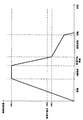
- FIG. 3 is a diagram showing an operation graph of the first embodiment of the present invention.
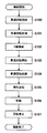
- FIG. 3 is a diagram showing an operation flowchart of the first embodiment of the present invention.
- FIG. 1 shows an overview of the mobile X-ray apparatus of the present invention.
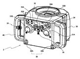
- FIG. 2 shows forms of the movable aperture portion and the case.
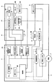
- FIG. 3 shows the internal configuration of the mobile X-ray apparatus of the present invention.
- the mobile X-ray apparatus of the present invention has a main body 1 and an X-ray tube 20 that generates X-rays, and generates X-rays by control from the main body 1.
- the generator 2 and an X-ray movable diaphragm 3 that adjusts the X-ray irradiation field are provided.
- the main body 1 is fixed on the carriage 4 and has an operation handle 8 for an operator to operate the traveling of the mobile X-ray apparatus.
- the X-ray generator 2 is supported by the arm 5.
- the arm 5 is supported by a column 6 installed on the carriage 4 so as to be slidable in the vertical and horizontal directions.
- the carriage 4 includes a wheel 7, a wheel lock unit 70 that brakes the wheel 7, and a wheel drive unit 71 (for example, a motor) for rotating and driving the wheel 7.
- the main body 1 is connected to the X-ray tube 20 in the X-ray generation unit 2 and connected to the rotary anode drive unit 22 that drives the rotary anode of the X-ray tube 20 and the high voltage generation unit 21 in the X-ray generation unit 2
- the high voltage control unit 23 that controls the high voltage generation unit 21, the filament control unit 24 that is connected to the X-ray tube 20 and heats the filament of the X-ray tube 20, and is supplied from the outside of the mobile X-ray apparatus.
- the power storage unit 25 that stores power and supplies power to each component, and the release switch state detection unit 50 that detects the release switch state of the release switch 39 of the handle 40 are provided.
- the main body 1 includes a control unit 90 that controls each component and an operation panel 26 that is connected to the control unit 90 and operates each component.
- a control unit 90 controls each component
- an operation panel 26 that is connected to the control unit 90 and operates each component.
- the main body 1 includes an image reading unit that reads out latent images accumulated in the X-ray detector as image data, and an image reading unit.
- An image processing unit that performs image processing on the X-ray signal output from the image processing unit, an image storage unit that stores the X-ray image output from the image processing unit, and a display unit that displays the X-ray image ing.
- the operation handle 8 has a travel switch (not shown) for controlling the wheel lock portion 70 and the wheel drive portion 71 of the wheel 7.
- the travel switch of the operation handle 8 is connected to the wheel lock unit 70 and the wheel drive unit 71, and the state (ON / OFF) of the travel switch is transmitted to the wheel lock unit 70 and the wheel drive unit 71.
- the operator When driving the mobile X-ray device, the operator holds the operation handle 8 and presses the travel switch. When the travel switch is pressed, the brake of the wheel 7 by the wheel lock unit 70 is released, and the wheel 7 is driven by the wheel drive unit 71.
- the X-ray generator 2 is supported through an arm 5 and a column 6 so as to be slidable in the vertical and horizontal directions.
- a rod-shaped guide pin 10 is installed on the lower surface of the arm 5.
- a through hole is provided at the tip of the guide pin 10.
- a column portion 9 (which may be a cylinder or a prism) is installed on the upper surface of the carriage 1.
- a guide hole for inserting the guide pin 10 and a holding part 60 for holding the guide pin 10 are provided on the upper part of the column part 9.
- the holding portion 60 has a rod portion that is inserted into the through hole at the tip of the guide pin 10.
- the column 6 is rotated around the vertical direction with respect to the carriage 1, and the arm 5 is Move to the left with respect to the column 6.
- the guide pin 10 installed on the arm 5 is inserted into the holding unit 60 installed on the pillar 9.
- the arm 5 can be fixed to the column portion 9 by inserting a rod portion into the through hole at the tip of the guide pin 10.
- the holding part 60 may fix the guide pin 10 using a magnet.
- the X-ray generator 2 and the X-ray movable diaphragm 3 are installed at the tip of the arm 5.
- an X-ray tube 20 is installed together with a high voltage generator 21.
- the X-ray generator 2 has an X-ray tube 20 and generates X-rays according to the X-ray imaging conditions set on the operation panel 26.
- the X-ray tube 20 includes a cathode that emits a thermoelectron beam from a filament supplied with a predetermined power by the filament control unit 24, and a rotating anode that has a target that collides the thermoelectron beam emitted by the cathode. Have.
- a tube voltage is applied to the cathode and rotating anode of the X-ray tube 20 by the high voltage controller 23 and the high voltage generator 21 in order to accelerate thermionic electrons emitted from the cathode.
- the thermoelectrons emitted from the filament by the applied tube voltage are accelerated before reaching the rotating anode, and the thermoelectrons collide with the rotating anode, thereby generating X-rays.
- the rotating anode Under the control of the rotating anode drive unit 22, the rotating anode is structured to rotate at high speed or low speed, and the actual area of the anode colliding with the thermoelectrons is increased by moving the portion that collides with the thermoelectrons and becomes high temperature. To do. Therefore, a large tube current can flow through the X-ray tube 20.
- the X-ray movable diaphragm 3 is rotatably mounted immediately below the X-ray generator 2.
- the X-ray movable diaphragm 3 has two pairs of movable restriction blades, and the X-ray irradiation field is adjusted by opening and closing each pair of movable restriction blades in the X direction and the Y direction.
- the X-ray generation unit 2 and the X-ray movable diaphragm 3 are moved to predetermined positions at the time of X-ray imaging by rotation of the support 6, raising / lowering along the support 6, and expansion / contraction of the arm 5.
- the X-ray generator 2 and the X-ray movable diaphragm 3 are moved to a predetermined position (home position) by the rotation of the support 6, the lifting / lowering along the support 6 and the extension / contraction of the arm 5.
- the X-ray movable diaphragm 3 is provided with an operation panel in front of a box-shaped case 30 opened at the bottom.
- This operation panel includes operation knobs 31A and 31B for controlling the movable restricting blades, an X-ray imaging condition setting unit 32, an X-ray imaging condition / distance indicator 33A and 33B, and an X-ray imaging condition display / distance display switch 34.
- a cart forward switch 35A, a cart reverse switch 35B, and an illumination switch 36 are provided.
- the operator rotates the operation knobs 31A and 31B to open and close the two pairs of movable restriction blades.
- the X-ray imaging condition setting unit 32 sets X-ray imaging conditions.
- X-ray imaging conditions the tube voltage and mAs value (product of tube current and time) of the X-ray tube 20 are usually used.
- the tube voltage and mAs value are adjusted by pressing the “+” and “-” buttons on the operation panel.
- the tube voltage is displayed on the display 33A, and the mAs value is displayed on the display 33B.
- the dolly forward / reverse switches 35A and 35B are connected to the wheel lock unit 70 and the wheel drive unit 71 to transmit the state of the dolly forward / reverse switch.
- the wheel 7 of the trolley 4 is braked by the wheel lock portion 70 and driven by the wheel drive portion 71 to advance the mobile X-ray device itself (trolley 4). ⁇ Can be retreated.
- the wheel lock unit 70 releases the brake of the wheel 7 and the wheel drive unit 71 is released by the time the cart forward / reverse switch 35A, 35B is pressed.
- Drive wheel 7. For example, if the time for pressing the cart forward / reverse switches 35A, 35B is short (for example, less than 1 second), the installation position of the mobile X-ray apparatus can be finely adjusted.
- the illumination switch 36 turns on an illumination lamp that illuminates the X-ray irradiation range.
- An ultrasonic rangefinder 38 is provided inside the movable X-ray diaphragm 3.
- the ultrasonic distance meter 38 includes ultrasonic transmission / reception units 38A and 38B and a calculation unit, transmits an ultrasonic wave from the transmission unit 38A, and detects a time until the reception unit 38B receives a reflected wave.
- a concave handle 40 is attached to both sides of the case 30 of the X-ray movable diaphragm 3, and a release switch 39 is provided inside the handle 40.
- the X-ray generator 2 and the X-ray diaphragm 3 are supported by the support 6 via the arm 5, and are moved by moving up and down along the support 6, expanding and contracting the arm 5, or rotating the support 6.
- a brake mechanism for fixing the X-ray generation unit 2 to a predetermined position is provided, and the X-ray generation unit 2 cannot be moved unless the brake mechanism is released.
- the release switch 39 of the brake mechanism By providing the release switch 39 of the brake mechanism in the X-ray movable diaphragm 3, the X-ray generator 2 and the X-ray movable diaphragm 3 can be moved. Since the release switch is provided inside the handle, as long as the handle 40 is grasped, the release switch 39 can be pressed simultaneously.
- Each signal line connecting the component of the main body 1 (for example, the rotary anode driving unit 22) and the component of the X-ray generation unit 2 or the case 30 (for example, the X-ray tube 20) passes through the arm 5 and the support column 6. Yes.
- the main body 1 includes a release switch state detection unit 50 that detects the release state of the release switch 39 (ON / OFF of the release switch 39) that releases the brake mechanism for fixing the X-ray generation unit 2 to a predetermined position. Yes.
- the release switch state detection unit 50 transmits the release state of the release switch 39 (release switch 39: ON) to the control unit 90.
- the control unit 90 instructs the rotating anode driving unit 22 to brake the rotating anode of the X-ray tube 20. Then, the rotary anode driving unit 22 brakes the rotary anode of the X-ray tube 20 and stops the rotation of the rotary anode.
- the rotating anode driving unit 22 rotates the rotating anode of the X-ray tube 20 at high speed at the time of activation (S100).
- the rotational speed (for example, 180 Hz) of the high-speed rotation is a frequency exceeding the mechanical vibration resonance point (for example, 70 Hz) of the bearing of the rotating anode.
- the rotary anode driving unit 22 drives the brake to decelerate so as to achieve normal rotation (eg, 60 Hz) that is lower than the vibration resonance point (eg, 70 Hz) (S103).
- normal rotation eg, 60 Hz
- vibration resonance point eg, 70 Hz
- the tube voltage of the X-ray tube 20 is small as an X-ray imaging condition, it is possible to capture images sufficiently even at normal rotation lower than the vibration resonance point. Therefore, if it is necessary to perform X-ray imaging with a small tube voltage X-ray photography is performed at this rotational speed.
- the rotary anode driving unit 22 decelerates the rotary anode to the normal rotation speed (S104), and then performs inertial rotation (S105).
- the release switch state detection unit 50 is controlled by the control unit 90. Is notified that the release switch 39 has been released.
- the control unit 90 instructs the rotating anode driving unit 22 to brake the rotating anode of the X-ray tube 20. Then, the rotating anode driving unit 22 applies a braking voltage to the main coil and the sub coil of the X-ray tube 20 (S106).
- the magnetic field generated in the stator coil (fixed side) is transmitted to the stator coil (rotation side), brakes the axis of the rotating anode, and stops the rotation of the rotating anode (S107).
- the travel switch of the operation handle 8 is connected to the wheel lock unit 70 and the wheel drive unit 71, and the state (ON / OFF) of the travel switch is transmitted. Further, the cart forward / reverse switches 35A and 35B are connected to the wheel lock unit 70 and the wheel drive unit 71, and the state (ON / OFF) of the cart forward / reverse switch 35 is transmitted.
- the wheel lock unit 70 and the wheel drive unit 71 transmit the drive state of the wheel lock unit 70 and the wheel drive unit 71 (the carriage 4 is moved) to the control unit 90, and the control unit 90 is connected to the rotary anode drive unit 22. Is instructed to brake the rotating anode of the X-ray tube 20. Then, the rotary anode driving unit 22 brakes the rotary anode of the X-ray tube 20 and stops the rotation of the rotary anode.
- a guide hole for inserting the guide pin 10 and the guide pin 10 are held at the upper part of the column portion 9 of the main body 1, and a holding portion 60 for fixing the arm 5 (X-ray generating portion 2) to the column portion 9 have. Furthermore, a holding detection unit 61 that is connected to the holding unit 60 and detects the holding state (home position) of the holding unit 60 is provided. The holding unit detection unit 61 is connected to the control unit 90 and transmits the holding state of the holding unit 60.
- the operator fixes the arm 5 to the holding part 60 of the column part 9.
- the holding detection unit 61 transmits the holding state of the holding detection unit 61 to the control unit 90, and the control unit 90 is connected to the rotary anode driving unit 22.
- An instruction is given to brake the rotating anode of the X-ray tube 20.
- the rotary anode driving unit 22 brakes the rotary anode of the X-ray tube 20 and stops the rotation of the rotary anode.
- the operation of this embodiment is the same in S101 to S105 and S107 in the form of the release switch 39, and S106 is achieved by replacing the above, so the description thereof is omitted here.
- the rotary anode driving unit 22 causes the rotary anode of the X-ray tube 20 rotating at a high speed to rotate normally (decelerate) and inertially rotate immediately after X-ray imaging.
- the rotary anode drive unit 22 brakes the rotary anode of the X-ray tube 20 and stops the rotation of the rotary anode.
- the rotating anode driving unit 22 rotates the rotating anode of the X-ray tube 20 at a high speed during startup (S200).
- the rotational speed (for example, 180 Hz) of the high-speed rotation is a frequency exceeding the mechanical vibration resonance point (for example, 70 Hz) of the bearing of the rotating anode.
- the release switch 39 When the operation of moving the X-ray generator 2 (arm 5) is performed, the release switch 39 is turned on (S205).
- the release switch state detection unit 50 transmits the release state of the release switch 39 (release switch 39: ON) to the control unit 90, and the control unit 90 detects that the rotating anode rotating at a high speed is connected to the rotating anode driving unit 22. It is driven and braked so as to achieve normal rotation (deceleration) (S206).
- the rotary anode drive unit 22 drives the brake to decelerate and brake so as to achieve normal rotation (eg, 60 Hz) that is lower than the vibration resonance point (eg, 70 Hz).
- the rotating anode driving unit 22 decelerates the rotating anode to the normal rotation speed (S207), and then performs inertial rotation (S208).
- the travel switch of the operation handle 8 or the cart forward / reverse switch 35A, 35B is pressed (ON), or the arm 5 is moved to the holding portion 60 of the column portion 9.
- the holding detection unit 61 detects that the holding state (home position) is detected (S209)
- the wheel lock unit 70, the wheel driving unit 71, or the holding detection unit 61 transmits the S209 operation to the control unit 90.
- the control unit 90 instructs the rotating anode driving unit 22 to brake the rotating anode of the X-ray tube 20.
- the rotating anode driving unit 22 applies a braking voltage to the main coil and the sub coil of the X-ray tube 20 (S210).
- the magnetic field generated in the stator coil (fixed side) is transmitted to the stator coil (rotation side), brakes the axis of the rotating anode, and stops the rotation of the rotating anode (S211).
- the release of the release switch 39 of the handle 40 is an operation of moving the components of the mobile X-ray apparatus (X-ray generation unit 2, arm 5, etc.), and the rotary anode drive unit 22 is immediately after X-ray imaging.
- the rotating anode of the X-ray tube 20 rotating at high speed is normally rotated (decelerated) and inertially rotated.
- the state of the operation handle 8 or the forward / backward switch 35 and the holding state of the holding unit 60 are operations to move the mobile X-ray apparatus itself (cart 4), and it is considered that X-ray imaging has ended, and the rotary anode driving unit 22 brakes the rotating anode of the X-ray tube 20 and stops the rotation of the rotating anode.
- the rotary anode drive unit 22 rotates the rotary anode of the X-ray tube 20 normally (decelerates), inertially rotates, or brakes to appropriately rotate the rotary anode. Can be controlled.
Landscapes
- Health & Medical Sciences (AREA)
- Life Sciences & Earth Sciences (AREA)
- Engineering & Computer Science (AREA)
- Medical Informatics (AREA)
- Radiology & Medical Imaging (AREA)
- Molecular Biology (AREA)
- Biophysics (AREA)
- Nuclear Medicine, Radiotherapy & Molecular Imaging (AREA)
- Optics & Photonics (AREA)
- Pathology (AREA)
- Physics & Mathematics (AREA)
- Biomedical Technology (AREA)
- Heart & Thoracic Surgery (AREA)
- High Energy & Nuclear Physics (AREA)
- Surgery (AREA)
- Animal Behavior & Ethology (AREA)
- General Health & Medical Sciences (AREA)
- Public Health (AREA)
- Veterinary Medicine (AREA)
- Pulmonology (AREA)
- Theoretical Computer Science (AREA)
- Apparatus For Radiation Diagnosis (AREA)
Abstract
移動型X線装置の消費電力を抑制するとともに、X線管の回転陽極の騒音を抑制する移動型X線装置及び回転陽極制御方法を提供するために、本体1と、本体1を搭載する台車4と、X線を発生させるX線管20を有したX線発生部2と、X線の照射野を調整するX線可動絞り3と、X線発生部2及びX線可動絞り3を支持するアーム5と、台車4上に設置され、アーム5を支持する支柱6とを備える移動型X線装置において、台車4又はX線発生部2を移動させる場合、X線管20の回転陽極の回転を制動させる回転陽極駆動部を備える。よって、移動型X線装置の消費電力を抑制するとともに、X線管の回転陽極の騒音を抑制することができる。
Description
本発明は、病院内を移動し、X線撮影を行なう移動型X線装置及び回転陽極制御方法に関するものである。
医療用X線装置として、病院内を移動し、X線撮影を行なう移動型X線装置がある。移動型X線装置は、主に病室や手術室で動くことができない患者や緊急患者などをX線撮影するために用いられている。
移動型X線装置は、台車と、台車に搭載された本体と、回転陽極(ロータ)を搭載し、被検体にX線を照射するX線管と、X線管に電圧を供給するX線電圧装置と、X線管を可動自在に本体に支持する支持機構とを有している。(例えば、特許文献1)。
X線撮影終了後、回転陽極を回転したままにしておくと、回転陽極の回転音が発生し続けることとなる。病室のように静寂な環境で使用する移動型X線装置では、この回転陽極の回転音によって他の患者の睡眠等を妨げることとなり、他の患者に迷惑をかける可能性がある。
また、移動型X線装置でX線管の出力電力を大きくする場合、X線管の回転陽極の焦点面の放熱性を高めるため、回転陽極の回転数を高くする。X線撮影後は回転陽極の回転に制動をかけて回転を停止させる必要がある。そのため、回転陽極に制動をかけるための消費電力が必要となり、バッテリ(電力蓄積部)の消費電力が大きくなる。消費電力が大きくなると、移動型X線装置の台車に搭載されたバッテリの消耗を助長し、X線撮影の枚数が制限される。よって、頻繁な充電作業が必要となる。
上記のようなバッテリの消耗に対応するため、バッテリ自体を増やすと、移動型X線装置の大型化・重量化がすすむため、バッテリを電源とするモータ駆動で自走するとバッテリの消耗が増えるという悪循環に陥る。
本発明の目的は、移動型X線装置の消費電力を抑制するとともに、X線管の回転陽極の騒音を抑制する移動型X線装置及び回転陽極制御方法を提供することである。
上記目的を達成するため、本発明は、本体と、前記本体を搭載する台車と、X線を発生させるX線管を有したX線発生部と、前記X線の照射野を調整するX線可動絞りと、前記X線発生部及び前記X線可動絞りを支持するアームと、前記台車上に設置され、前記アームを支持する支柱とを備える移動型X線装置において、前記台車又は前記X線発生部を移動させる場合、前記X線管の回転陽極の回転を制動させる回転陽極駆動部を備える。よって、移動型X線装置の消費電力を抑制するとともに、X線管の回転陽極の騒音を抑制することができる。
また、前記X線発生部を所定位置に固定するためのブレーキ機構を解除する解除部と、前記解除部の解除状態を検出する解除部状態検出部とを備え、前記解除部状態検出部の前記解除状態に基づいて、前記回転陽極駆動部は前記X線管の回転陽極の回転を制動する。よって、解除スイッチによる制動を行なうことができる。
また、前記台車は、車輪と、前記車輪にブレーキをかける車輪ロック部と、前記車輪を回転させて駆動させるための車輪駆動部を備え、前記車輪ロック部と前記車輪駆動部の駆動状態に基づいて、前記回転陽極駆動部は前記X線管の回転陽極の回転を制動する。よって、操作ハンドル、前進・後退スイッチによる制動を行なうことができる。
また、前記本体は、前記アームを保持する保持部と、前記保持部の保持状態を検出する保持検出部とを備え、前記保持検出部から検出される前記保持状態に基づいて、前記回転陽極駆動部は前記X線管の回転陽極の回転を制動する。よって、保持部による制動を行なうことができる。
また、前記台車又は前記X線発生部を移動させる前に、前記回転陽極駆動部は前記回転陽極の回転を減速させ、惰性回転を行なう。よって、移動型X線装置の消費電力を抑制することができる。
さらに、本体と、前記本体を搭載する台車と、X線を発生させるX線管を有したX線発生部と、前記X線の照射野を調整するX線可動絞りと、前記X線発生部及び前記X線可動絞りを支持するアームと、前記台車上に設置され、前記アームを支持する支柱とを備える移動型X線装置において、前記X線発生部又は前記アームを移動させる場合、前記X線管の回転陽極の回転を減速させるとともに惰性回転させ、前記台車を移動させる場合、前記X線管の回転陽極を制動させ、回転陽極の回転を停止する回転陽極駆動部を備える。よって、移動型X線装置の消費電力を抑制するとともに、X線管の回転陽極の騒音を抑制することができる。
X線管の回転陽極を回転し、X線撮影を行なうステップと、該X線撮影後、前記X線管を有するX線発生部、又は移動型X線装置の台車を所定位置に移動させる場合、前記回転陽極の回転を制動させるステップとを含む回転陽極制御方法である。よって、移動型X線装置の消費電力を抑制するとともに、X線管の回転陽極の騒音を抑制することができる。
本発明によれば、移動型X線装置の消費電力を抑制するとともに、X線管の回転陽極の騒音を抑制することができる。
(第1の実施形態)
本発明の第1の実施形態について図を用いて説明する。図1は、本発明の移動型X線装置の概観図を示すものである。図2は、可動絞り部とケースの形態を示すものである。図3は、本発明の移動型X線装置の内部構成を示すものである。
本発明の第1の実施形態について図を用いて説明する。図1は、本発明の移動型X線装置の概観図を示すものである。図2は、可動絞り部とケースの形態を示すものである。図3は、本発明の移動型X線装置の内部構成を示すものである。
図1~図3に示すように、本発明の移動型X線装置は、本体1と、X線を発生させるX線管20を有し、本体1からの制御によりX線を発生させるX線発生部2と、X線の照射野を調整するX線可動絞り3とを有している。本体1は台車4上に固設され、操作者が移動型X線装置の走行を操作するための操作ハンドル8を有している。また、X線発生部2は、アーム5によって支持される。アーム5は、台車4上に設置された支柱6によって上下左右スライド自在に支持される。
図1、図3に示すように、台車4には、車輪7と、車輪7にブレーキをかける車輪ロック部70と、車輪7を回転させて駆動させるための車輪駆動部71(例えば、モータ)を有している。本体1は、X線発生部2内のX線管20に接続され、X線管20の回転陽極を駆動する回転陽極駆動部22と、X線発生部2内の高電圧発生部21に接続され、高電圧発生部21を制御する高電圧制御部23と、X線管20に接続され、X線管20のフィラメントを加熱するフィラメント制御部24と、移動型X線装置の外部から供給された電力が蓄積され、各構成要素に電力を供給する電力蓄積部25と、取っ手40の解除スイッチ39の解除スイッチ状態を検出する解除スイッチ状態検出部50とを有している。
また、本体1は、各構成要素を制御する制御部90と、制御部90に接続され、各構成要素を操作する操作パネル26とを有している。操作パネル26では、例えばX線管20のX線撮影条件等を設定することができる。
なお、図示はないが、被検体を透過したX線を検出するX線検出器があり、本体1は、X線検出器に蓄積された潜像を画像データとして読み出す画像読取部と、画像読取部から出力されたX線信号に対して画像処理を行なう画像処理部と、画像処理部から出力されたX線画像を記憶する画像記憶部と、X線画像を表示する表示部とを有している。
図1、図3に示すように、操作ハンドル8は、車輪7の車輪ロック部70と車輪駆動部71を制御するための走行スイッチ(図示せず)を有している。操作ハンドル8の走行スイッチは車輪ロック部70と車輪駆動部71に接続され、車輪ロック部70と車輪駆動部71に走行スイッチの状態(ON・OFF)が伝達される。
移動型X線装置を走行させる際、操作者は操作ハンドル8を握り、走行スイッチを押す。走行スイッチが押されると、車輪ロック部70による車輪7のブレーキが解除され、車輪駆動部71によって車輪7を駆動する。
移動型X線装置を静止させる際、操作者は操作ハンドル8から手を離し、走行スイッチを解除する。走行スイッチが解除されると、車輪ロック部70によって車輪7にブレーキが掛けられる。
図1、図3に示すように、X線発生部2はアーム5と支柱6を介して、上下左右スライド自在に支持されている。アーム5の下面には、棒状のガイドピン10が設置されている。ガイドピン10の先端には貫通穴が設置されている。台車1の上面には、柱部9(円柱、角柱でもよい)が設置されている。柱部9の上部には、ガイドピン10を挿入させるためのガイド穴とガイドピン10を保持するための保持部60を有している。保持部60は、ガイドピン10先端の貫通穴に挿入する棒部を有している。
アーム5を柱部9に固定する際、図1で示される状態(アーム5が支柱6に対して右側)から、台車1に対して鉛直方向を中心にして支柱6を回転させ、アーム5を支柱6に対して左側に移動させる。アーム5に設置されているガイドピン10を柱部9に設置されている保持部60に挿入する。そして、ガイドピン10先端の貫通穴に棒部を挿入することにより、アーム5を柱部9に固定することができる。なお、保持部60はマグネットを用いて、ガイドピン10を固定してもよい。
アーム5の先端には、X線発生部2とX線可動絞り3が設置されている。X線発生部2には、X線管20が高電圧発生部21とともに設置されている。X線発生部2は、X線管20を有し、操作パネル26で設定されたX線撮影条件に応じてX線を発生する。X線管20は、フィラメント制御部24によって、所定の電源が供給されたフィラメントからの熱電子ビームを放射する陰極と、この陰極によって放射された熱電子ビームを衝突させるターゲットを有する回転陽極とを有している。X線管20の陰極と回転陽極には、高電圧制御部23及び高電圧発生部21によって、カソードから放出された熱電子を加速するために管電圧が印加される。この印加される管電圧によりフィラメントから放出される熱電子は、回転陽極に到達するまでに加速され、熱電子が回転陽極に衝突することにより、X線を発生させることができる。
回転陽極駆動部22の制御によって、回転陽極が高速回転又は低速回転する構造になっており、熱電子と衝突し高温になる部分を移動させることにより、熱電子と衝突する陽極の実面積が増大する。そのため、X線管20に大きな管電流を流すことができる。
X線可動絞り3はX線発生部2の直下に回転自在に装着されている。X線可動絞り3は、2対の可動制限羽根を有し、各対の可動制限羽根がX方向およびY方向に開閉することでX線の照射野を調整する。
X線発生部2とX線可動絞り3は、支柱6の回転、支柱6沿いの昇降およびアーム5の伸縮によりX線撮影時に所定の位置に移動される。X線撮影終了後、X線発生部2とX線可動絞り3は、支柱6の回転、支柱6沿いの昇降およびアーム5の伸縮により所定の位置(ホームポジション)に移動される。
X線発生部2とX線可動絞り3は、支柱6の回転、支柱6沿いの昇降およびアーム5の伸縮によりX線撮影時に所定の位置に移動される。X線撮影終了後、X線発生部2とX線可動絞り3は、支柱6の回転、支柱6沿いの昇降およびアーム5の伸縮により所定の位置(ホームポジション)に移動される。
図2に示すように、X線可動絞り3は、下方が開口した箱型のケース30の正面に操作パネルが設けられている。この操作パネルには、可動制限羽根を制御する操作つまみ31A、31B、X線撮影条件設定器32、X線撮影条件兼距離表示器33A、33B、X線撮影条件表示と距離表示の切替スイッチ34、台車前進スイッチ35A、台車後進スイッチ35B、照光スイッチ36が設けられている。
操作者は、操作つまみ31A、31Bを回転し、2対の可動制限羽根を開閉する。X線撮影条件設定器32はX線撮影条件を設定する。X線撮影条件には、通常、X線管20の管電圧とmAs値(管電流と時間の積)が用いられる。ここでは、操作パネルにある「+」と「-」のボタンを押すことで管電圧とmAs値を調整する。管電圧は表示器33Aに、mAs値は表示器33Bに表示される。
台車前進・後進スイッチ35A、35Bは、車輪ロック部70と車輪駆動部71に接続され、台車前進・後進スイッチの状態が伝達される。台車前進・後進スイッチ35A、35Bは、その操作により、台車4の車輪7を車輪ロック部70でブレーキを解除し、車輪駆動部71で駆動して移動型X線装置自体(台車4)を前進・後退させることができる。操作者が、台車前進・後進スイッチ35A、35Bを押すと、台車前進・後進スイッチ35A、35Bが押された時間分だけ、車輪ロック部70は車輪7のブレーキを解除し、車輪駆動部71は車輪7を駆動する。例えば、台車前進・後進スイッチ35A、35Bを押す時間が短ければ(例えば1秒未満)、移動型X線装置の設置位置の微調整を行なうことができる。
照光スイッチ36は、X線の照射範囲を照光する照光ランプを点灯させるものである。この可動X線絞り3の内部には、超音波距離計38が設けられている。超音波距離計38は、超音波の送受信部38A、38Bと演算部とを有し、送信部38Aから超音波を送信し、受信部38Bで反射波を受信するまでの時間を検知する。
X線可動絞り3のケース30の両側には凹型の取っ手40が取り付けられ、その取っ手40の内側には解除スイッチ39が設けられている。X線発生部2およびX線絞り3は、アーム5を介して支柱6に支持され、この支柱6沿いの昇降、アーム5の伸縮あるいは支柱6の回転によって移動される。その際、X線発生部2を所定位置に固定するためのブレーキ機構が設けられ、このブレーキ機構を解除してからでないとX線発生部2を移動することができない。X線可動絞り3に、このブレーキ機構の解除スイッチ39を設けることで、X線発生部2およびX線可動絞り3の移動を可能にする。解除スイッチは取っ手の内側に設けられているため、取っ手40を握りさえすれば、同時に解除スイッチ39を押すことができる。
なお、本体1の構成要素(例えば回転陽極駆動部22)と、X線発生部2又はケース30の構成要素(例えばX線管20)とを結ぶ各信号線は、アーム5と支柱6内を通じている。
ここで、取っ手40の解除スイッチ39の解除状態により、X線管20の回転陽極を制動させる形態について説明する。
本体1には、X線発生部2を所定位置に固定するためのブレーキ機構を解除する解除スイッチ39の解除状態(解除スイッチ39のON・OFF)を検出する解除スイッチ状態検出部50を備えている。X線撮影が行なわれ、X線発生部2(アーム5)を移動させる際、解除スイッチ状態検出部50は、制御部90に解除スイッチ39の解除状態(解除スイッチ39:ON)を伝達し、制御部90は、回転陽極駆動部22に対し、X線管20の回転陽極を制動させるよう指示する。そして、回転陽極駆動部22は、X線管20の回転陽極を制動させ、回転陽極の回転を停止する。
本実施形態の動作について、図4のグラフと図5のフローチャートを用いて具体的に説明する。X線撮影条件としてX線管20の管電圧が大きい場合、回転陽極の焦点面の放熱性を高めるため、回転陽極の回転数を高くする必要がある。そのため、回転陽極駆動部22は、起動時にX線管20の回転陽極を高速に回転する(S100)。この高速回転の回転数(例えば180Hz)は、回転陽極の軸受けの機械的な振動共振点(例えば70Hz)を越える周波数である。
そして、回転陽極を高速に回転したら(S101)、回転陽極の回転数が高い状態でX線撮影を行なう(S102)。回転陽極駆動部22は、X線撮影直後、高速回転している回転陽極が普通回転(例えば60Hz)になるように減速駆動して制動する(S103)。高速回転している回転陽極を制動しないままにしておくと、回転陽極の回転は徐々に減少し、回転陽極の回転数と陽極軸受けの振動共振点と一致し、回転陽極に大きな振動が発生するからである。具体的には、回転陽極駆動部22は、X線撮影後は振動共振点(例えば70Hz)より低い回転数となる普通回転(例えば60Hz)になるように減速駆動して制動する(S103)。なお、X線撮影条件としてX線管20の管電圧が小さい場合、振動共振点より低い普通回転でも充分に撮影をすることができるため、管電圧が小さい状態でX線撮影する必要があれば、この回転数でX線撮影を行なう。
回転陽極駆動部22は、上記の通り、回転陽極を普通回転に回転数に減速した(S104)後、惰性回転を行なう(S105)。そして、取っ手40の解除スイッチ39が押され、X線発生部2を所定位置に固定するためのブレーキ機構のブレーキを解除することが行なわれた場合、解除スイッチ状態検出部50は、制御部90に解除スイッチ39が解除されたことを伝達する。制御部90は、回転陽極駆動部22に対し、X線管20の回転陽極を制動させるように指示する。そして、回転陽極駆動部22は、X線管20のメインコイル及びサブコイルに制動電圧を印加させる(S106)。ステータコイル(固定側)にて発生した磁界によって、ステータコイル(回転側)に磁界が伝わり、回転陽極の軸を制動し、回転陽極の回転を停止する(S107)。
回転陽極駆動部22は、上記の通り、回転陽極を普通回転に回転数に減速した(S104)後、惰性回転を行なう(S105)。そして、取っ手40の解除スイッチ39が押され、X線発生部2を所定位置に固定するためのブレーキ機構のブレーキを解除することが行なわれた場合、解除スイッチ状態検出部50は、制御部90に解除スイッチ39が解除されたことを伝達する。制御部90は、回転陽極駆動部22に対し、X線管20の回転陽極を制動させるように指示する。そして、回転陽極駆動部22は、X線管20のメインコイル及びサブコイルに制動電圧を印加させる(S106)。ステータコイル(固定側)にて発生した磁界によって、ステータコイル(回転側)に磁界が伝わり、回転陽極の軸を制動し、回転陽極の回転を停止する(S107)。
次に、操作ハンドル8の走行スイッチ又は前進・後退スイッチ35の状態により、X線管20の回転陽極を制動させる形態について説明する。
操作ハンドル8の走行スイッチは車輪ロック部70と車輪駆動部71に接続され、走行スイッチの状態(ON・OFF)が伝達される。また、台車前進・後進スイッチ35A、35Bは、車輪ロック部70と車輪駆動部71に接続され、台車前進・後進スイッチ35の状態(ON・OFF)が伝達される。
X線撮影が行なわれ、移動型X線装置を移動させる際、操作者は操作ハンドル8を握り、操作ハンドル8の走行スイッチを押したり、台車前進・後進スイッチ35A、35Bを押したりする。操作ハンドル8の走行スイッチ又は台車前進・後進スイッチ35A、35Bが押される(ON)と、車輪ロック部70によって車輪7のブレーキが解除され、車輪駆動部71によって車輪7を駆動する。
その際、車輪ロック部70と車輪駆動部71は、制御部90に車輪ロック部70と車輪駆動部71の駆動状態(台車4が移動)を伝達し、制御部90は、回転陽極駆動部22に対し、X線管20の回転陽極を制動させるよう指示する。そして、回転陽極駆動部22は、X線管20の回転陽極を制動させ、回転陽極の回転を停止する。
なお、本実施形態の動作については、解除スイッチ39の形態のS101~S105、S107は同様であり、S106は上記と置き換えれば達成されるので、ここでは説明は省略する。
次に、保持部60の保持状態により、X線管20の回転陽極を制動させる形態について説明する。
本体1の柱部9の上部には、ガイドピン10を挿入させるためのガイド穴とガイドピン10を保持し、アーム5(X線発生部2)を柱部9に固定するための保持部60を有している。さらに、保持部60に接続され、保持部60の保持状態(ホームポジション)を検出する保持検出部61を有している。保持部検出部61は、制御部90に接続され、保持部60の保持状態を伝達する。
X線撮影が行なわれ、移動型X線装置を移動させる際、操作者はアーム5を柱部9の保持部60に固定する。アーム5が柱部9の保持部60に固定されると、保持検出部61は、制御部90に保持検出部61の保持状態を伝達し、制御部90は、回転陽極駆動部22に対し、X線管20の回転陽極を制動させるよう指示する。そして、回転陽極駆動部22は、X線管20の回転陽極を制動させ、回転陽極の回転を停止する。
なお、本実施形態の動作については、解除スイッチ39の形態のS101~S105、S107は同様であり、S106は上記と置き換えれば達成されるので、ここでは説明は省略する。
以上、回転陽極駆動部22は、X線撮影直後、高速で回転しているX線管20の回転陽極を普通回転(減速)させるとともに惰性回転させる。また、取っ手40の解除スイッチ39の解除、操作ハンドル8又は前進・後退スイッチ35の状態、保持部60の保持状態等、移動型X線装置自体(台車4)又は移動型X線装置の構成要素(X線発生部2、アーム5等)を移動させる際、X線撮影が終了したとみなし、回転陽極駆動部22は、X線管20の回転陽極を制動させ、回転陽極の回転を停止する。
以上、回転陽極駆動部22は、X線撮影直後、高速で回転しているX線管20の回転陽極を普通回転(減速)させるとともに惰性回転させる。また、取っ手40の解除スイッチ39の解除、操作ハンドル8又は前進・後退スイッチ35の状態、保持部60の保持状態等、移動型X線装置自体(台車4)又は移動型X線装置の構成要素(X線発生部2、アーム5等)を移動させる際、X線撮影が終了したとみなし、回転陽極駆動部22は、X線管20の回転陽極を制動させ、回転陽極の回転を停止する。
このように、X線管20の回転陽極の普通回転(減速)、惰性回転又は制動を効率よく行なうことにより、移動型X線装置の消費電力を抑制することができるとともに、X線管20の回転陽極の制動を適時行なうため、X線管20の回転陽極の騒音を抑制することができる。
(第2の実施形態)
次に第2の実施形態を図1~3、6、7を用いて説明する。第1の実施形態と異なる点は、解除スイッチ39、操作ハンドル8の走行スイッチ、台車前進・後進スイッチ35A、35B、保持部60の状態によって、X線管20の回転陽極の制御を異ならせる点である。
次に第2の実施形態を図1~3、6、7を用いて説明する。第1の実施形態と異なる点は、解除スイッチ39、操作ハンドル8の走行スイッチ、台車前進・後進スイッチ35A、35B、保持部60の状態によって、X線管20の回転陽極の制御を異ならせる点である。
第2の実施形態の構成については、第1の実施形態と同様であるため、説明を省略する。
本実施形態の動作について、図6のグラフと図7のフローチャートを用いて具体的に説明する。X線撮影条件としてX線管20の管電圧が大きい場合、回転陽極の焦点面の放熱性を高めるため、回転陽極の回転数を高くする必要がある。そのため、回転陽極駆動部22は、起動時にX線管20の回転陽極を高速に回転する(S200)。この高速回転の回転数(例えば180Hz)は、回転陽極の軸受けの機械的な振動共振点(例えば70Hz)を越える周波数である。
本実施形態の動作について、図6のグラフと図7のフローチャートを用いて具体的に説明する。X線撮影条件としてX線管20の管電圧が大きい場合、回転陽極の焦点面の放熱性を高めるため、回転陽極の回転数を高くする必要がある。そのため、回転陽極駆動部22は、起動時にX線管20の回転陽極を高速に回転する(S200)。この高速回転の回転数(例えば180Hz)は、回転陽極の軸受けの機械的な振動共振点(例えば70Hz)を越える周波数である。
そして、回転陽極を高速に回転したら(S201)、回転陽極の回転数が高い状態でX線撮影を行なう(S202)。X線撮影後、回転陽極駆動部22は、回転数が高い状態で回転陽極を惰性回転する(S203)。操作者は、S202でX線撮影したX線画像を表示部で確認し、被検体の同じ部位について再撮影を行なうかどうかを決定する(S204)。再撮影を行なう場合、S200~S203を繰り返す。再撮影を行なわない場合、X線発生部2(アーム5)を移動させて、アーム5を柱部9に固定して移動型X線装置を移動させる状態にする。
X線発生部2(アーム5)を移動させる動作が行なわれる際、解除スイッチ39がONとなる(S205)。解除スイッチ状態検出部50は、制御部90に解除スイッチ39の解除状態(解除スイッチ39:ON)を伝達し、制御部90は、回転陽極駆動部22に対し、高速回転している回転陽極が普通回転(減速)になるように駆動して制動する(S206)。具体的には、回転陽極駆動部22は、X線撮影後は振動共振点(例えば70Hz)より低い回転数となる普通回転(例えば60Hz)になるように減速駆動して制動する。回転陽極駆動部22は、上記の通り、回転陽極を普通回転に回転数に減速した(S207)後、惰性回転を行なう(S208)。
移動型X線装置を移動させる動作が行なわれる際、例えば、操作ハンドル8の走行スイッチ又は台車前進・後進スイッチ35A、35Bが押されたり(ON)、アーム5を柱部9の保持部60に固定し、保持検出部61は保持状態(ホームポジション)を検出されたりした(S209)場合、車輪ロック部70、車輪駆動部71、又は保持検出部61は、制御部90に上記S209動作を伝達する。制御部90は、回転陽極駆動部22に対し、X線管20の回転陽極を制動させるように指示する。そして、回転陽極駆動部22は、X線管20のメインコイル及びサブコイルに制動電圧を印加させる(S210)。ステータコイル(固定側)にて発生した磁界によって、ステータコイル(回転側)に磁界が伝わり、回転陽極の軸を制動し、回転陽極の回転を停止する(S211)。
以上、取っ手40の解除スイッチ39の解除は、移動型X線装置の構成要素(X線発生部2、アーム5等)を移動させる動作であり、回転陽極駆動部22は、X線撮影直後、高速で回転しているX線管20の回転陽極を普通回転(減速)させるとともに惰性回転させる。
操作ハンドル8又は前進・後退スイッチ35の状態、保持部60の保持状態は、移動型X線装置自体(台車4)を移動させる動作であり、X線撮影が終了したとみなし、回転陽極駆動部22は、X線管20の回転陽極を制動させ、回転陽極の回転を停止する。
これら2種の動作を区別して、回転陽極駆動部22は、X線管20の回転陽極を普通回転(減速)させるとともに惰性回転をさせたり、制動させたりすることにより、回転陽極の回転を適宜制御することができる。
このように、X線管20の回転陽極の普通回転(減速)、惰性回転又は制動を効率よく行なうことにより、移動型X線装置の消費電力を抑制することができるとともに、X線管20の回転陽極の制動を適時行なうため、X線管20の回転陽極の騒音を抑制することができる。
1 本体、2 X線発生部、3 X線可動絞り、4 台車、5 アーム、6 支柱、7 車輪、8 操作ハンドル、9 柱部、10 ガイドピン、20 X線管、21 高電圧発生部、22 回転陽極駆動部、23 高電圧制御部、24 フィラメント制御部、25 電力蓄積部、26 操作パネル、35 前進・後退スイッチ、39 解除スイッチ、40 取っ手、50 解除スイッチ状態検出部、60 保持部、61 保持検出部、70 車輪ロック部、71 車輪駆動部、90 制御部
Claims (11)
- 本体と、前記本体を搭載する台車と、X線を発生させるX線管を有したX線発生部と、前記X線の照射野を調整するX線可動絞りと、前記X線発生部及び前記X線可動絞りを支持するアームと、前記台車上に設置され、前記アームを支持する支柱とを備える移動型X線装置において、
前記台車又は前記X線発生部の移動が検出された場合、前記X線管の回転陽極の回転を制動させる回転陽極駆動部を備えることを特徴とする移動型X線装置。 - 前記X線発生部を所定位置に固定するためのブレーキ機構を解除する解除部と、前記解除部の解除状態を検出する解除部状態検出部とを備え、前記解除部状態検出部の前記解除状態に基づいて、前記回転陽極駆動部は前記X線管の回転陽極の回転を制動することを特徴とする請求項1記載の移動型X線装置。
- 前記解除部は、前記X線可動絞りのケースの取っ手に設置されることを特徴とする請求項2記載の移動型X線装置。
- 前記台車は、車輪と、前記車輪にブレーキをかける車輪ロック部と、前記車輪を回転させて駆動させるための車輪駆動部を備え、前記車輪ロック部と前記車輪駆動部の駆動状態に基づいて、前記回転陽極駆動部は前記X線管の回転陽極の回転を制動することを特徴とする請求項1記載の移動型X線装置。
- 前記台車を移動させるためのスイッチを備え、前記スイッチは前記車輪ロック部と前記車輪駆動部に接続され、前記車輪ロック部と前記車輪駆動部を介して、前記回転陽極駆動部に前記スイッチの状態が伝達されることを特徴とする請求項4記載の移動型X線装置。
- 前記本体は、前記アームを保持する保持部と、前記保持部の保持状態を検出する保持検出部とを備え、前記保持検出部から検出される前記保持状態に基づいて、前記回転陽極駆動部は前記X線管の回転陽極の回転を制動することを特徴とする請求項1記載の移動型X線装置。
- 前記台車又は前記X線発生部を移動させる前に、前記回転陽極駆動部は前記回転陽極の回転を減速させ、惰性回転を行なうことを特徴とする請求項1記載の移動型X線装置。
- 前記回転陽極駆動部は、前記回転陽極の軸受けの振動共振点より低い回転数まで、前記回転陽極の回転を制動させることを特徴とする請求項1記載の移動型X線装置。
- 前記回転陽極駆動部は、前記X線発生部又は前記アームを移動させる場合、前記X線管の回転陽極の回転を減速させるとともに惰性回転させ、前記台車を移動させる場合、前記X線管の回転陽極を制動させ、回転陽極の回転を停止することを特徴とする請求項1記載の移動型X線装置。
- X線管の回転陽極を回転し、X線撮影を行なうステップと、該X線撮影後、前記X線管を有するX線発生部、又は移動型X線装置の台車を所定位置に移動させる場合、前記回転陽極の回転を所定回転数に制動するステップとを含む回転陽極制御方法。
- 前記所定回転数は、前記回転陽極の軸受けの振動共振点より低い回転数であることを特徴とする請求項10記載の回転陽極制御方法。
Priority Applications (1)
| Application Number | Priority Date | Filing Date | Title |
|---|---|---|---|
| JP2010540472A JP5566303B2 (ja) | 2008-11-25 | 2009-11-24 | 移動型x線装置及び回転陽極制御方法 |
Applications Claiming Priority (2)
| Application Number | Priority Date | Filing Date | Title |
|---|---|---|---|
| JP2008-298949 | 2008-11-25 | ||
| JP2008298949 | 2008-11-25 |
Publications (1)
| Publication Number | Publication Date |
|---|---|
| WO2010061809A1 true WO2010061809A1 (ja) | 2010-06-03 |
Family
ID=42225684
Family Applications (1)
| Application Number | Title | Priority Date | Filing Date |
|---|---|---|---|
| PCT/JP2009/069780 Ceased WO2010061809A1 (ja) | 2008-11-25 | 2009-11-24 | 移動型x線装置及び回転陽極制御方法 |
Country Status (2)
| Country | Link |
|---|---|
| JP (1) | JP5566303B2 (ja) |
| WO (1) | WO2010061809A1 (ja) |
Cited By (11)
| Publication number | Priority date | Publication date | Assignee | Title |
|---|---|---|---|---|
| JP2013182764A (ja) * | 2012-03-01 | 2013-09-12 | Hitachi Medical Corp | X線装置 |
| JP2014033877A (ja) * | 2012-08-09 | 2014-02-24 | Hitachi Medical Corp | X線撮影装置 |
| JP2014079570A (ja) * | 2012-09-28 | 2014-05-08 | Canon Inc | 移動型放射線撮影装置、放射線撮影システム、及び制御方法 |
| WO2014184843A1 (ja) * | 2013-05-13 | 2014-11-20 | 株式会社 島津製作所 | 回診用x線撮影装置 |
| JP2015047172A (ja) * | 2013-08-29 | 2015-03-16 | 株式会社東芝 | 移動型x線診断装置 |
| JP2017056354A (ja) * | 2017-01-04 | 2017-03-23 | コニカミノルタ株式会社 | 移動型x線撮影装置 |
| JP2019063505A (ja) * | 2017-10-03 | 2019-04-25 | キヤノンメディカルシステムズ株式会社 | X線診断装置およびx線高電圧装置 |
| JP2019118714A (ja) * | 2018-01-10 | 2019-07-22 | キヤノンメディカルシステムズ株式会社 | X線診断装置 |
| US10638998B2 (en) | 2016-06-07 | 2020-05-05 | Canon Medical Systems Corporation | X-ray diagnostic apparatus and medical-information processing apparatus configured to control a rotating speed of a rotary anode of an X-ray tube by deriving an acquiring condition from a fluoroscopic image |
| US20210313136A1 (en) * | 2020-04-07 | 2021-10-07 | Shimadzu Corporation | X-ray imaging apparatus |
| KR20220138579A (ko) * | 2021-04-06 | 2022-10-13 | (주)디알젬 | 암 컬럼 고정 구조를 갖는 이동형 엑스선 장치 |
Citations (14)
| Publication number | Priority date | Publication date | Assignee | Title |
|---|---|---|---|---|
| JPS4625578B1 (ja) * | 1967-12-06 | 1971-07-23 | ||
| JPS5013494Y1 (ja) * | 1969-12-27 | 1975-04-24 | ||
| JPS58209099A (ja) * | 1982-05-31 | 1983-12-05 | Hitachi Ltd | 回転陽極x線管装置 |
| JPH04322097A (ja) * | 1991-04-23 | 1992-11-12 | Toshiba Corp | コードレス回診用x線装置の電源装置 |
| JPH08273891A (ja) * | 1995-03-31 | 1996-10-18 | Shimadzu Corp | X線装置 |
| JPH09299359A (ja) * | 1996-05-16 | 1997-11-25 | Hitachi Medical Corp | 可搬型放射線装置 |
| JPH10225450A (ja) * | 1997-02-14 | 1998-08-25 | Toshiba Corp | X線診断装置 |
| JP2000173796A (ja) * | 1998-12-04 | 2000-06-23 | Shimadzu Corp | スタータ装置 |
| JP2001110591A (ja) * | 1999-10-08 | 2001-04-20 | Hitachi Medical Corp | X線高電圧装置及びx線装置 |
| JP2002034964A (ja) * | 2000-07-28 | 2002-02-05 | Hitachi Medical Corp | 移動型x線装置 |
| JP2004121405A (ja) * | 2002-09-30 | 2004-04-22 | Hitachi Medical Corp | X線装置 |
| JP2006141669A (ja) * | 2004-11-19 | 2006-06-08 | Shimadzu Corp | 移動式x線撮影装置 |
| JP2006141777A (ja) * | 2004-11-22 | 2006-06-08 | Shimadzu Corp | 移動式x線撮影装置 |
| JP2008229396A (ja) * | 2008-07-01 | 2008-10-02 | Hitachi Medical Corp | X線装置 |
-
2009
- 2009-11-24 JP JP2010540472A patent/JP5566303B2/ja not_active Expired - Fee Related
- 2009-11-24 WO PCT/JP2009/069780 patent/WO2010061809A1/ja not_active Ceased
Patent Citations (14)
| Publication number | Priority date | Publication date | Assignee | Title |
|---|---|---|---|---|
| JPS4625578B1 (ja) * | 1967-12-06 | 1971-07-23 | ||
| JPS5013494Y1 (ja) * | 1969-12-27 | 1975-04-24 | ||
| JPS58209099A (ja) * | 1982-05-31 | 1983-12-05 | Hitachi Ltd | 回転陽極x線管装置 |
| JPH04322097A (ja) * | 1991-04-23 | 1992-11-12 | Toshiba Corp | コードレス回診用x線装置の電源装置 |
| JPH08273891A (ja) * | 1995-03-31 | 1996-10-18 | Shimadzu Corp | X線装置 |
| JPH09299359A (ja) * | 1996-05-16 | 1997-11-25 | Hitachi Medical Corp | 可搬型放射線装置 |
| JPH10225450A (ja) * | 1997-02-14 | 1998-08-25 | Toshiba Corp | X線診断装置 |
| JP2000173796A (ja) * | 1998-12-04 | 2000-06-23 | Shimadzu Corp | スタータ装置 |
| JP2001110591A (ja) * | 1999-10-08 | 2001-04-20 | Hitachi Medical Corp | X線高電圧装置及びx線装置 |
| JP2002034964A (ja) * | 2000-07-28 | 2002-02-05 | Hitachi Medical Corp | 移動型x線装置 |
| JP2004121405A (ja) * | 2002-09-30 | 2004-04-22 | Hitachi Medical Corp | X線装置 |
| JP2006141669A (ja) * | 2004-11-19 | 2006-06-08 | Shimadzu Corp | 移動式x線撮影装置 |
| JP2006141777A (ja) * | 2004-11-22 | 2006-06-08 | Shimadzu Corp | 移動式x線撮影装置 |
| JP2008229396A (ja) * | 2008-07-01 | 2008-10-02 | Hitachi Medical Corp | X線装置 |
Cited By (18)
| Publication number | Priority date | Publication date | Assignee | Title |
|---|---|---|---|---|
| JP2013182764A (ja) * | 2012-03-01 | 2013-09-12 | Hitachi Medical Corp | X線装置 |
| JP2014033877A (ja) * | 2012-08-09 | 2014-02-24 | Hitachi Medical Corp | X線撮影装置 |
| JP2014079570A (ja) * | 2012-09-28 | 2014-05-08 | Canon Inc | 移動型放射線撮影装置、放射線撮影システム、及び制御方法 |
| WO2014184843A1 (ja) * | 2013-05-13 | 2014-11-20 | 株式会社 島津製作所 | 回診用x線撮影装置 |
| JP6079873B2 (ja) * | 2013-05-13 | 2017-02-15 | 株式会社島津製作所 | 回診用x線撮影装置 |
| JP2015047172A (ja) * | 2013-08-29 | 2015-03-16 | 株式会社東芝 | 移動型x線診断装置 |
| US10638998B2 (en) | 2016-06-07 | 2020-05-05 | Canon Medical Systems Corporation | X-ray diagnostic apparatus and medical-information processing apparatus configured to control a rotating speed of a rotary anode of an X-ray tube by deriving an acquiring condition from a fluoroscopic image |
| JP2017056354A (ja) * | 2017-01-04 | 2017-03-23 | コニカミノルタ株式会社 | 移動型x線撮影装置 |
| JP7224825B2 (ja) | 2017-10-03 | 2023-02-20 | キヤノンメディカルシステムズ株式会社 | X線診断装置およびx線高電圧装置 |
| JP2019063505A (ja) * | 2017-10-03 | 2019-04-25 | キヤノンメディカルシステムズ株式会社 | X線診断装置およびx線高電圧装置 |
| JP2019118714A (ja) * | 2018-01-10 | 2019-07-22 | キヤノンメディカルシステムズ株式会社 | X線診断装置 |
| JP7055639B2 (ja) | 2018-01-10 | 2022-04-18 | キヤノンメディカルシステムズ株式会社 | X線診断装置 |
| JP2021164567A (ja) * | 2020-04-07 | 2021-10-14 | 株式会社島津製作所 | X線撮影装置 |
| US11545331B2 (en) * | 2020-04-07 | 2023-01-03 | Shimadzu Corporation | X-ray imaging apparatus |
| US20210313136A1 (en) * | 2020-04-07 | 2021-10-07 | Shimadzu Corporation | X-ray imaging apparatus |
| JP7388276B2 (ja) | 2020-04-07 | 2023-11-29 | 株式会社島津製作所 | X線撮影装置 |
| KR20220138579A (ko) * | 2021-04-06 | 2022-10-13 | (주)디알젬 | 암 컬럼 고정 구조를 갖는 이동형 엑스선 장치 |
| KR102471031B1 (ko) | 2021-04-06 | 2022-11-25 | (주)디알젬 | 암 컬럼 고정 구조를 갖는 이동형 엑스선 장치 |
Also Published As
| Publication number | Publication date |
|---|---|
| JPWO2010061809A1 (ja) | 2012-04-26 |
| JP5566303B2 (ja) | 2014-08-06 |
Similar Documents
| Publication | Publication Date | Title |
|---|---|---|
| JP5566303B2 (ja) | 移動型x線装置及び回転陽極制御方法 | |
| CN102858248B (zh) | 移动型x射线装置以及移动型x射线装置的控制方法 | |
| JP5232802B2 (ja) | 移動型x線装置 | |
| CN101951836B (zh) | 移动式x射线装置 | |
| CN104955398B (zh) | X射线诊断装置、以及x射线诊断装置的控制方法 | |
| JP6251725B2 (ja) | 移動型x線装置 | |
| WO2019064670A1 (ja) | 放射線撮影装置 | |
| JPWO2011162149A1 (ja) | 天井走行式のx線撮像装置及びその制御方法 | |
| US7441952B2 (en) | Method and system for X-ray diagnosis of an examination object | |
| JP6103033B2 (ja) | X線撮影装置 | |
| WO2014192111A1 (ja) | X線撮影装置 | |
| JP7388276B2 (ja) | X線撮影装置 | |
| JP2009195500A (ja) | 移動型x線装置 | |
| JP5978060B2 (ja) | X線撮影装置 | |
| JP7055639B2 (ja) | X線診断装置 | |
| JP5601832B2 (ja) | 回転陽極型x線装置およびx線ct装置 | |
| JP6362852B2 (ja) | 移動型x線診断装置 | |
| JP2004350833A (ja) | 移動型x線装置 | |
| JP2006081694A (ja) | X線撮影装置 | |
| JP2015054143A (ja) | 移動型x線診断装置 | |
| JP5212162B2 (ja) | X線撮像装置 | |
| JP2010184055A (ja) | X線管装置及びそれを用いたx線ct装置 | |
| JP2004191184A (ja) | 放射線絞り装置 | |
| JP2016005510A (ja) | X線撮影装置 | |
| JP2014000286A (ja) | X線撮影装置 |
Legal Events
| Date | Code | Title | Description |
|---|---|---|---|
| 121 | Ep: the epo has been informed by wipo that ep was designated in this application |
Ref document number: 09829057 Country of ref document: EP Kind code of ref document: A1 |
|
| ENP | Entry into the national phase |
Ref document number: 2010540472 Country of ref document: JP Kind code of ref document: A |
|
| NENP | Non-entry into the national phase |
Ref country code: DE |
|
| 122 | Ep: pct application non-entry in european phase |
Ref document number: 09829057 Country of ref document: EP Kind code of ref document: A1 |