WO2010055705A1 - 車両用乗員拘束装置 - Google Patents
車両用乗員拘束装置 Download PDFInfo
- Publication number
- WO2010055705A1 WO2010055705A1 PCT/JP2009/059324 JP2009059324W WO2010055705A1 WO 2010055705 A1 WO2010055705 A1 WO 2010055705A1 JP 2009059324 W JP2009059324 W JP 2009059324W WO 2010055705 A1 WO2010055705 A1 WO 2010055705A1
- Authority
- WO
- WIPO (PCT)
- Prior art keywords
- belt
- seat
- occupant
- vehicle
- air
- Prior art date
Links
Images


Classifications
-
- B—PERFORMING OPERATIONS; TRANSPORTING
- B60—VEHICLES IN GENERAL
- B60N—SEATS SPECIALLY ADAPTED FOR VEHICLES; VEHICLE PASSENGER ACCOMMODATION NOT OTHERWISE PROVIDED FOR
- B60N2/00—Seats specially adapted for vehicles; Arrangement or mounting of seats in vehicles
- B60N2/68—Seat frames
- B60N2/688—Particular seat belt attachment and guiding
-
- B—PERFORMING OPERATIONS; TRANSPORTING
- B60—VEHICLES IN GENERAL
- B60R—VEHICLES, VEHICLE FITTINGS, OR VEHICLE PARTS, NOT OTHERWISE PROVIDED FOR
- B60R21/00—Arrangements or fittings on vehicles for protecting or preventing injuries to occupants or pedestrians in case of accidents or other traffic risks
- B60R21/02—Occupant safety arrangements or fittings, e.g. crash pads
- B60R21/16—Inflatable occupant restraints or confinements designed to inflate upon impact or impending impact, e.g. air bags
- B60R21/18—Inflatable occupant restraints or confinements designed to inflate upon impact or impending impact, e.g. air bags the inflatable member formed as a belt or harness or combined with a belt or harness arrangement
-
- B—PERFORMING OPERATIONS; TRANSPORTING
- B60—VEHICLES IN GENERAL
- B60R—VEHICLES, VEHICLE FITTINGS, OR VEHICLE PARTS, NOT OTHERWISE PROVIDED FOR
- B60R22/00—Safety belts or body harnesses in vehicles
- B60R22/18—Anchoring devices
- B60R22/26—Anchoring devices secured to the seat
-
- B—PERFORMING OPERATIONS; TRANSPORTING
- B60—VEHICLES IN GENERAL
- B60R—VEHICLES, VEHICLE FITTINGS, OR VEHICLE PARTS, NOT OTHERWISE PROVIDED FOR
- B60R22/00—Safety belts or body harnesses in vehicles
- B60R22/02—Semi-passive restraint systems, e.g. systems applied or removed automatically but not both ; Manual restraint systems
- B60R2022/027—Four-point seat belt systems, e.g. with the two upper points connected together
-
- B—PERFORMING OPERATIONS; TRANSPORTING
- B60—VEHICLES IN GENERAL
- B60R—VEHICLES, VEHICLE FITTINGS, OR VEHICLE PARTS, NOT OTHERWISE PROVIDED FOR
- B60R22/00—Safety belts or body harnesses in vehicles
- B60R22/18—Anchoring devices
- B60R2022/1818—Belt guides
Definitions
- the present invention relates to a vehicle occupant restraint device for restraining an occupant seated on a seat at the time of a collision to the seat.
- an air belt guide is provided on the shoulder portion of the seat back that stands up outside the inflated air belt in the seat width direction (for example, Japanese Patent Application Laid-Open No. 2007-2007). No. 112415. Also, regarding the air belt device, see US Patent Application Publication No. 2003/0168837, Japanese Patent Publication No. 2001-521462.
- a vehicle occupant restraint device includes a seat belt that includes a body restraint portion that is pulled out of a retractor and restrains the occupant's upper body when being mounted on the occupant, and the seat back. And a belt insertion portion into which an upper portion of the upper body restraining portion of the seat belt is inserted.
- the portion of the seat belt that is pulled out from the retractor is mainly used as the upper body restraining portion, and is attached to the passenger to restrain the upper body of the passenger from the vehicle seat.
- the portion directly above the upper body restraining portion of the seat belt is inserted into the belt insertion portion of the seat back.
- a belt insertion portion is formed by denting a part in the seat width direction at the upper end of the seat back.
- the seat belt is restricted from moving in the seat width direction by the recessed walls located on both sides in the seat width direction at the portion inserted into the belt insertion portion. That is, the position of the seat belt is regulated by the belt insertion portion.
- the position of the seat belt can be regulated without occupying the passenger compartment space.
- the portion of the seat belt that is inserted into the belt insertion portion and the portion including the upper body restraining portion are provided with an inflatable belt portion that is inflated and deployed by gas supply. Also good.
- the occupant in the event of a vehicle collision, the occupant is protected by inflating and deploying the inflating belt portion of the seat belt.
- the inflatable belt portion is partly inserted into the belt insertion portion in the longitudinal direction, movement in the sheet width direction is restricted by the belt insertion portion even in the expanded and deployed state. That is, in the vehicle occupant restraint device, the position of the inflated and deployed inflatable belt portion is effectively restricted by the belt insertion portion.
- a vehicle occupant restraint device includes a seat belt that includes a body restraint portion that is pulled out of a retractor and restrains the occupant's upper body when the occupant is worn, and the seat belt.
- An inflatable belt portion that is provided in a portion including the upper body restraining portion and an upper portion of the upper body restraining portion and is expanded by gas supply and a part in the seat width direction at the upper end of the seat back is recessed.
- a belt insertion portion that includes a recess formed so as to allow a lower portion of the expansion belt portion in the vehicle vertical direction to enter the recess when the expansion belt portion is deployed.
- the portion of the seat belt that is pulled out from the retractor is mainly used as the upper body restraining portion, and is attached to the passenger to restrain the upper body of the passenger from the vehicle seat.
- the portion directly above the upper body restraining portion of the seat belt is inserted into the belt insertion portion of the seat back.
- the occupant is protected by inflating and deploying the inflating belt portion of the seat belt.
- the lower portion of the inflatable belt portion in the vehicle vertical direction enters the recess of the belt insertion portion.
- the movement of the expansion belt portion in the sheet width direction is restricted by the concave walls located on both sides in the sheet width direction. That is, the position of the inflated and deployed inflatable belt portion is regulated by the belt insertion portion.
- the recessed part of a belt insertion part is formed by denting the upper end part of a seat back.
- the position of the seat belt can be regulated without occupying the passenger compartment space.
- the concave portion of the belt insertion portion may always be configured to insert the expansion belt portion of the seat belt (including before expansion and deployment), and the expansion belt is expanded and expanded as the expansion belt portion is expanded and deployed.
- the structure which inserts a part may be sufficient.
- a pair of left and right seat belts each provided with the expansion belt portion may be provided, and a pair of left and right belt insertion portions may be provided at an upper end of the seat back.
- the upper body of the occupant is restrained by the upper body restraining portions of the pair of left and right seat belts.
- the inflating belt portions of the pair of left and right seat belts When the inflating belt portions of the pair of left and right seat belts are inflated and deployed, they act to interfere with each other and retreat in the seat width direction.
- the left and right inflatable belt portions are supported by the concave walls on the outer side in the vehicle width direction of the belt insertion portions inserted therein (the concave walls generate the support reaction force of the inflatable belt portion). The occupant is well protected by the inflatable belt portion.
- the expansion belt portion is provided with a flat surface maintaining structure for maintaining a contact surface with the bottom surface of the belt insertion portion when the expansion belt portion is deployed. It is also good.
- the contact surface with the bottom surface of the belt insertion portion of the inflated belt in the unfolded process and in the unfolded state is maintained flat (flat) by the flat surface maintaining structure. For this reason, the movement of the deployed expansion belt in the sheet width direction is more effectively limited.
- the vehicle occupant restraint device has an excellent effect that the position of the seat belt can be regulated without occupying the passenger compartment space.
- FIG. 1 is a perspective view showing a schematic overall configuration of an air belt device according to a first embodiment of the present invention. It is a front view showing typically the principal part of the air belt device concerning a 1st embodiment of the present invention. It is a front sectional view at the time of non-expansion showing an enlarged state of insertion of the air belt constituting the air belt device according to the first embodiment of the present invention into the belt insertion portion. It is a front sectional view at the time of expansion which shows an insertion state to a belt insertion part of an air belt which constitutes an air belt device concerning a 1st embodiment of the present invention expanded.
- FIG. 6 is a front sectional view schematically showing a main part of a four-point air belt device according to a third embodiment of the present invention.
- arrow FR, arrow UP, and arrow W described appropriately in each figure respectively indicate the forward direction (traveling direction), the upward direction, and the vehicle width direction of the automobile to which the air belt device 10 is applied. These directions substantially coincide with the front direction, the upward direction, the right side and the left side in the seat width direction of the vehicle seat 11 to which the air belt device 10 is applied.
- FIG. 1 is a perspective view showing a non-use state of the air belt device 10 applied to the vehicle seat 11.
- the air belt device 10 includes a retractor 14 that winds up one end side of the seat belt 12 so as to be drawable.
- the retractor 14 is disposed behind the seat back 16 constituting the vehicle seat 11 in the vehicle front-rear direction, and is fixed to, for example, a package tray rim as a vehicle body.
- the other end side of the seat belt 12 is fixed to the rear side of the seat cushion 18 constituting the vehicle seat 11 by an anchor (not shown).
- the seat belt 12 extends in the vehicle vertical direction on one end side in the width direction of the vehicle seat 11, and a tongue plate 20 is provided at a substantially middle portion in the vertical direction.
- the tongue plate 20 can be coupled to and released from the buckle 22 disposed on the opposite side in the width direction of the vehicle seat 11.
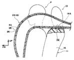
- the shoulder belt portion 12 ⁇ / b> A as the upper body restraint portion is obliquely suspended over the occupant's upper body from the shoulder portion of the seat back 16 to the tongue plate 20 by coupling the tongue plate 20 to the buckle 22. It is supposed to be.
- the seat belt 12 restrains the upper body of the seated occupant P at the shoulder belt portion 12A as shown in FIG. 2, and the lap belt portion (not shown) from the tongue plate 20 to the anchor is the waist of the seated occupant P. Is to be restrained.
- the air belt device 10 is an air belt device based on a three-point seat belt device.
- the retractor 14 is disposed behind the seat back 16 as described above.
- the seat belt 12 mounted by the seated occupant P of the vehicle seat 11 is configured such that a portion directly above the shoulder belt portion 12A is wound around a shoulder portion 16A (belt insertion portion 32 described later) of the seat back 16.
- a shoulder anchor or the like for guiding the seat belt 12 is not provided between the retractor 14 and the shoulder portion 16 ⁇ / b> A of the seat back 16.
- the seat belt 12 including the shoulder belt portion 12A is configured as an inflatable belt portion 24 that is inflated and expanded by receiving a gas supply from an inflator (not shown).
- the air belt 24 is set to at least a portion wound around the shoulder portion 16A of the seat back 16 and a portion covering almost the entire length of the shoulder belt portion 12A when the seat belt 12 is worn by the seated passenger P of the vehicle seat 11. Yes.
- the air belt 24 includes a cover 26 as a belt body, a stretchable mesh webbing 28 provided on the inside of the cover 26, and a folded state inside the mesh webbing 28.
- the provided airbag 30 is a main part.
- the air belt 24 is supplied with gas from an inflator (not shown) arranged on the retractor 14 side or the anchor side, and the airbag 30 is inflated.
- the air belt 24 is generally shown in an imaginary line in FIG. 2, FIG. 3B, and FIG. It expands and expands as expected. Portions other than the air belt 24 in the seat belt 12 are joined to the cover 26 by sewing or the like.
- the inflator is operated by an ECU (not shown) to supply gas to the airbag 30 when, for example, a frontal collision (unavoidable) of the vehicle is detected or predicted.
- the air belt device 10 includes a belt insertion portion 32 for regulating the position of the seat belt 12 (air belt 24).
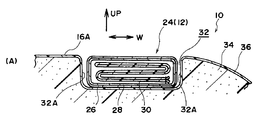
- the belt insertion portion 32 is formed as a recess by recessing a part in the seat width direction of the shoulder portion 16A of the seat back 16 so as to open upward in the vehicle vertical direction over the entire length in the vehicle front-rear direction. ing.
- a set portion of the air belt 24 in the seat belt 12 is slidably inserted into the belt insertion portion 32. At least when the seat belt 12 is worn by the occupant P seated on the vehicle seat 11, the air belt 24 enters the belt insertion portion 32 so as to be slidable in the longitudinal direction.
- the belt insertion portion 32 has a width equal to or greater than the width of the air belt 24.
- the width and depth of the belt insertion portion 32 are inserted into the belt insertion portion 32 so that a portion (cross section) inflated immediately above the shoulder portion 16A of the seat back 16 in the air belt 24 is approximately 1/3 of the vertical dimension. It is decided to be.
- the retractor 14 is disposed at the same position in the vehicle vertical direction or below the shoulder 16A of the seat back 16 (bottom of the belt insertion portion 32).
- the air belt 24 is inserted into the belt insertion portion 32 without using a shoulder anchor or the like for guiding the seat belt 12 (air belt 24) (wrapped around the bottom of the belt insertion portion 32). It can be configured.
- the belt insertion portion 32 dents a part of a cushion material (pad) 34 constituting the seat back 16 and provides a skin material 36 in the dent so that the seat back 16 Are integrally formed.
- the seated passenger P of the vehicle seat 11 joins the tongue plate 20 to the buckle 22 while pulling out the seat belt 12 from the retractor 14 when the seat belt 12 is worn.
- the shoulder belt portion 12A restrains the upper body of the seated occupant P
- a lap belt portion restrains the waist of the seated occupant P.
- the ECU activates the inflator. Then, gas is supplied from the inflator to the airbag 30 of the air belt 24, and the air belt 24 is inflated and deployed into a predetermined shape. This protects the occupant against a frontal collision.
- the air belt 24 enters the belt insertion portion 32 formed in the seat back 16.
- the air belt 24 is restricted in movement in the sheet width direction by the pair of concave walls 32A facing the sheet width direction in the belt insertion portion 32 in the expanded and deployed state (in the process). That is, the position of the inflated and deployed air belt 24 with respect to the vehicle seat 11 (occupant) is regulated.
- movement of the air belt 24 to the outside in the sheet width direction is restricted by the concave wall 32A on the outside in the sheet width direction.
- the inflatable belt 24 is inflated and deployed at a position suitable for protecting the occupant, thereby effectively protecting the occupant.
- belt insertion part 32 is constituted by denting shoulder part 16A of seat back 16, it can regulate the position of air belt 24, without occupying vehicle interior space.
- the air belt apparatus 10 it is not necessary to provide a guide member that occupies the vehicle compartment space for restricting the position of the air belt 24. Therefore, the number of parts and the cost can be reduced. Further, the number of members protruding into the passenger compartment space is reduced, so that the limited passenger compartment space can be effectively used, the usability can be improved, and the appearance can be improved.
- the air belt device 10 is configured to allow the air belt 24 (the seat belt 12) to enter the belt insertion portion 32. Therefore, as shown in FIG. 5, the seat belt 12 (particularly, the shoulder belt portion 12 ⁇ / b> A) can be properly attached to an occupant with a low seating height such as a child. For example, in the comparative example that does not include the belt insertion portion 32, the shoulder belt portion 12A is likely to be interfered with the neck portion with respect to the seat occupant P having a relatively low seat height, as indicated by an imaginary line in FIG.
- the portion around which the seat belt 12 is wound is lower than that of the comparative example.
- the shoulder belt portion 12A is disposed at a position where the shoulder belt portion 12A hardly interferes with the neck portion with respect to an occupant having a relatively low seat height.
- the movement of the seat belt 12 toward the cervical side of the seat occupant P is restricted by the concave wall 32A on the inner side in the vehicle width direction of the belt insertion portion 32.
- the air belt device 10 contributes to properly mounting the shoulder belt portion 12A to the small seated occupant P having a low seating height such as a child.
- FIG. 6 is a schematic front view showing an air belt device 40 as a vehicle occupant restraint device according to a second embodiment of the present invention.
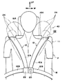
- the air belt device 40 is different from the air belt device 10 which is a three-point air belt device in that the air belt device 40 includes a pair of left and right seat belts 12 and is configured as a so-called four-point air belt device.
- the left and right seat belts 12 are wound around a retractor 14 whose upper end side is not shown, and the lower end side is fixed to the rear portion of the seat cushion 18 via an anchor.
- a tongue plate 20 is provided in a substantially middle portion of one seat belt 12, and a buckle 22 is provided in a substantially middle portion of the other seat belt 12.
- the pair of left and right shoulder belt portions 12A restrain the state of the seated occupant P of the vehicle seat 11. It is like that.
- the lap belt portion 12B constituted by the left and right seat belts 12 restrains the waist of the seated occupant P.
- belt insertion portions 32 are formed on the left and right shoulder portions 16A of the seat back 16, respectively. Therefore, a part of the air belt 24 in the left and right seat belts 12 is inserted into the corresponding belt insertion portion 32.
- Other configurations in the inflatable belt device 40 are the same as the corresponding configurations in the inflatable belt device 10 including portions not shown.
- the air belt device 40 according to the second embodiment basically the same effect can be obtained by the same operation as the air belt device 10 according to the first embodiment.
- the air belt device 40 in the four-point type air belt device 40, as shown by an imaginary line in FIG. 6, there is a case in which the inflated and deployed left and right air belts 24 interfere with each other and retreat outward in the vehicle width direction.
- the left and right belt insertion portions 32 restrict the position of each air belt 24 to an appropriate position. That is, the concave wall 32A on the outer side in the seat width direction in each belt insertion portion 32 supports the reaction force of the air belt 24, and the position of each air belt 24 is restricted to an appropriate position. For this reason, in the air belt apparatus 40, the passenger
- FIG. 7 The principal part of the air belt apparatus 50 as a passenger
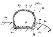
- the air belt device 50 is different from the air belt device 10 according to the first embodiment in that a thick belt 52 as a deformation restricting portion is provided in the air belt 24.
- the thick belt 52 is formed to be thick using, for example, the same material (fiber) as the airbag 30 and is integrated with the airbag 30 by sewing or the like.
- the thick belt 52 may be integrated with the cover 26 and the mesh webbing 28 instead of the airbag 30.
- the thick belt 52 is set within a predetermined range where the air belt 24 is inserted into the belt insertion portion 32 when the seat belt 12 is worn by at least an occupant and on the lower side in the vehicle vertical direction (the bottom side of the belt insertion portion 32). Has been.
- the developed shape of the inflatable belt 24 is regulated by the thick belt 52 so that the lower end portion is substantially flat as shown in FIG.
- the other structure of the air belt apparatus 50 is the same as the corresponding structure of the air belt apparatus 10 or the air belt apparatus 40 including the part which is not shown in figure.
- the air belt device 50 according to the third embodiment, basically the same effect can be obtained by the same operation as the air belt devices 10 and 40 according to the first or second embodiment.
- the air belt 24 since the lower end of the air belt 24 in the unfolding process and in the unfolding state is substantially flat, the air belt 24 (the seat belt 12) is difficult to roll against the force in the seat width direction.
- the displacement of the air belt 24 in the seat width direction with respect to the belt insertion portion 32 is less likely to occur, and the air belt 24 is more reliably inflated and deployed at a position suitable for occupant protection. Contribute to safeguarding.
- the present invention is not limited to this.
- the present invention may be applied to, for example, a three-point or four-point seat belt device in which the seat belt 12 does not have the air belt 24.
- the provision of the belt insertion portion 32 contributes to properly mounting the seat belt 12 (particularly, the shoulder belt portion 12A) to a small passenger.
- the present invention is not limited to this.
- a belt insertion portion into which the air belt 24 is inserted when the air belt 24 is expanded and deployed may be provided in the shoulder portion 16A of the seat back 16.
- the tear portion of the skin material 36 is broken by the developing pressure of the air belt 24, or
- the present invention is not limited to this.
- the present invention is applicable if the longitudinal direction part of the seat belt 12 or the air belt 24 is arranged (wound) along at least a part of the shoulder part 16A of the seat back 16 in the vehicle front-rear direction. Is possible. Therefore, for example, the present invention can be applied to a configuration in which the retractor 14 is disposed in the seat back 16 and the seat belt 12 and the air belt 24 are led out from the shoulder portion 16A and disposed along the shoulder portion 16A. it can.
- the belt insertion part 32 should just be provided in the vehicle front with respect to the belt derivation
Landscapes
- Engineering & Computer Science (AREA)
- Mechanical Engineering (AREA)
- Aviation & Aerospace Engineering (AREA)
- Transportation (AREA)
- Automotive Seat Belt Assembly (AREA)
- Air Bags (AREA)
- Seats For Vehicles (AREA)
Abstract
車室空間を占有することなく、シートベルトの位置を規制することができる車両用乗員拘束装置を得る。 エアベルト装置(10)は、シートバック(16)に対する車両前後方向の後方に配置されたリトラクタ(14)と、乗員に装着される際にリトラクタ(14)から引き出され該乗員Pの上体を拘束するためのショルダベルト部(12A)を含むシートベルト(12)と、シートバック(16)上端におけるシート幅方向の一部を凹ませて形成されシートベルト(12)におけるショルダベルト部(12A)の上側部分が入り込まされるベルト挿入部(32)と、を備えている。
Description
本発明は、少なくとも衝突時にシートに着座した乗員を該シートに拘束するための車両用乗員拘束装置に関する。
エアベルトがシートバックの肩部を通過する構成において、膨張したエアベルトに対しシート幅方向の外側で起立されるエアベルトガイドをシートバックの肩部に設けたものが知られている(例えば、特開2007-112415号公報参照。また、エアベルト装置について、米国特許出願公開2003/0168837号明細書、特表2001-521462号公報参照)
しかしながら、上記の如き従来の技術では、シートバックの肩部から車室空間を占有するベルトガイドを設ける必要があり、この点に改善の余地がある。
本発明は、車室空間を占有することなく、シートベルトの位置を規制することができる車両用乗員拘束装置を得ることが目的である。
本発明の第1の態様に係る車両用乗員拘束装置は、乗員に装着される際にリトラクタから引き出され、乗員の上体を拘束するための上体拘束部を含むシートベルトと、前記シートバックの上端におけるシート幅方向の一部を凹ませて形成され、前記シートベルトにおける前記上体拘束部の上側部分が入り込まされるベルト挿入部と、を備えている。
上記の態様によれば、シートベルトにおけるリトラクタから引き出された部分が主に上体拘束部とされ、乗員に装着されて該乗員の上体を車両用シートに対し拘束する。この装着状態で、シートベルトにおける上体拘束部の直上部分は、シートバックのベルト挿入部に入り込まされている。
ここで、本車両用乗員拘束装置では、シートバックの上端におけるシート幅方向の一部を凹ませることで、ベルト挿入部が形成されている。そして、シートベルトは、ベルト挿入部に入り込まされた部分において、シート幅方向の両側に位置する凹壁にて該シート幅方向の移動が制限される。すなわち、シートベルトの位置がベルト挿入部によって規制される。
このように、本発明の第1の態様に係る車両用乗員拘束装置では、車室空間を占有することなく、シートベルトの位置を規制することができる。
上記の態様において、前記シートベルトにおける前記ベルト挿入部に入り込まされる部分及び前記上体拘束部を含む部分には、ガス供給により膨張して展開される膨張ベルト部が設けられている、構成としても良い。
上記の態様によれば、例えば車両衝突の際には、シートベルトの膨張ベルト部が膨張、展開されることで、乗員が保護される。ここで、膨張ベルト部は、その長手方向の一部において、ベルト挿入部に入り込まされているため、膨張、展開された状態においてもベルト挿入部によってシート幅方向への移動が制限される。すなわち、本車両用乗員拘束装置では、膨張、展開された膨張ベルト部の位置がベルト挿入部によって効果的に規制される。
本発明の第2の態様に係る車両用乗員拘束装置は、乗員に装着される際にリトラクタから引き出され、乗員の上体を拘束するための上体拘束部を含むシートベルトと、前記シートベルトにおける前記上体拘束部及び該上体拘束部の上側部分を含む部分に設けられ、ガス供給により膨張して展開される膨張ベルト部と、前記シートバックの上端におけるシート幅方向の一部を凹ませて形成された凹部を含み、前記膨張ベルト部が展開される際に該膨張ベルト部における車両上下方向の下部を前記凹部に入り込ませるベルト挿入部と、を備えている。
上記の態様によれば、シートベルトにおけるリトラクタから引き出された部分が主に上体拘束部とされ、乗員に装着されて該乗員の上体を車両用シートに対し拘束する。この装着状態で、シートベルトにおける上体拘束部の直上部分は、シートバックのベルト挿入部に入り込まされている。例えば車両衝突の際には、シートベルトの膨張ベルト部が膨張、展開されることで、乗員が保護される。
ここで、本車両用乗員拘束装置では、少なくとも膨張ベルト部が膨張、展開された際には、該膨張ベルト部の車両上下方向の下部がベルト挿入部の凹部に入り込んだ状態となっている。このため、膨張ベルト部は、シート幅方向の両側に位置する凹壁にて該シート幅方向の移動が制限される。すなわち、膨張、展開された膨張ベルト部の位置がベルト挿入部によって規制される。そして、ベルト挿入部の凹部は、シートバックの上端部を凹ませることで形成されている。
このように、本発明の第2の態様に係る車両用乗員拘束装置では、車室空間を占有することなく、シートベルトの位置を規制することができる。なお、ベルト挿入部の凹部は、常に(膨張、展開前を含み)シートベルトの膨張ベルト部を挿入させる構成であっても良く、膨張ベルト部が膨張、展開されるに伴って、該膨張ベルト部を挿入させる構成であっても良い。
上記の態様において、それぞれ前記膨張ベルト部が設けられた左右一対の前記シートベルトを備え、前記シートバックの上端には、左右一対の前記ベルト挿入部が設けられている、構成としても良い。
上記の態様によれば、左右一対のシートベルトにおける上体拘束部にて乗員の上体が拘束される。これら左右一対のシートベルトの膨張ベルト部が膨張、展開されると、これらは互いに干渉してシート幅方向に退け合う力が作用する。ここで、左右の膨張ベルト部は、それぞれ入り込まされたベルト挿入部の車幅方向外側の凹壁にて支持される(凹壁が膨張ベルト部の支持反力を発生する)ので、これら左右の膨張ベルト部にて乗員が良好に保護される。
上記の態様において、前記膨張ベルト部には、該膨張ベルト部が展開される際に前記ベルト挿入部の底面との接触面を平面状に維持するための平面維持構造が設けられている、構成としても良い。
上記の態様によれば、展開過程、展開状態の膨張ベルトにおけるベルト挿入部の底面との接触面が平面維持構造によって平面(平坦)状に維持される。このため、展開された膨張ベルトのシート幅方向の移動が一層効果的に制限される。
以上説明したように本発明に係る車両用乗員拘束装置は、車室空間を占有することなく、シートベルトの位置を規制することができるという優れた効果を有する。
本発明の第1の実施形態に係る車両用乗員拘束装置としてのエアベルト装置10について、図1~図5に基づいて説明する。なお、各図に適宜記す矢印FR、矢印UP、矢印Wは、それぞれエアベルト装置10が適用された自動車の前方向(進行方向)、上方向、車幅方向を示している。これらの各方向は、エアベルト装置10が適用された車両用シート11の前方向、上方向、シート幅方向の右側、左側に略一致している。
図1には、車両用シート11に適用されたエアベルト装置10の非使用状態が斜視図にて示されている。この図に示される如く、エアベルト装置10は、シートベルト12の一端側を引き出し可能に巻き取るリトラクタ14を備えている。リトラクタ14は、車両用シート11を構成するシートバック16に対する車両前後方向の後方に配置されており、例えば車体としてのパッケージトレイリム等に固定されている。シートベルト12の他端側は、車両用シート11を構成するシートクッション18の後部側方に図示しないアンカによって固定されている。
この不使用状態で、シートベルト12は、車両用シート11の幅方向一端側で車両上下方向に延在されており、その上下方向における略中間部にはタングプレート20が設けられている。タングプレート20は、車両用シート11の幅方向反対側に配置されたバックル22に対する結合及び該結合の解除が可能とされている。
このエアベルト装置10では、タングプレート20をバックル22に結合することで、シートバック16の肩部からタングプレート20にかけての上体拘束部としてのショルダベルト部12Aが乗員の上体に斜めに掛け渡されるようになっている。この状態でシートベルト12は、図2に示される如くショルダベルト部12Aにおいて着座乗員Pの上体を拘束すると共に、タングプレート20からアンカにかけてのラップベルト部(図示省略)が着座乗員Pの腰部を拘束するようになっている。
したがって、エアベルト装置10は、3点式のシートベルト装置をベースとしたエアベルト装置とされている。また、エアベルト装置10では、上記の通りリトラクタ14がシートバック16の後方に配置されている。このため、車両用シート11の着座乗員Pによる装着状態のシートベルト12は、ショルダベルト部12Aの直上部分がシートバック16の肩部16A(後述するベルト挿入部32)に巻き掛けられる構成とされている。この実施形態では、リトラクタ14とシートバック16の肩部16Aとの間には、シートベルト12をガイドするショルダアンカ等が設けられない構成とされている。
そして、シートベルト12におけるショルダベルト部12Aを含む少なくとも一部は、図示しないインフレータからガス供給を受けて膨張、展開される膨張ベルト部としてのエアベルト24として構成されている。エアベルト24は、車両用シート11の着座乗員Pによるシートベルト12の装着状態で、少なくともシートバック16の肩部16Aに巻き掛けられる部分、及びショルダベルト部12Aのほぼ全長に亘る部分に設定されている。
エアベルト24について補足すると、図3Aに示される如く、エアベルト24は、ベルト本体としてのカバー26と、カバー26の内側に設けられた伸縮可能なメッシュウエビング28と、メッシュウエビング28の内側に折り畳み状態で設けられたエアバッグ30とを主要部として構成されている。
このエアベルト24は、リトラクタ14側又はアンカ側に配置された図示しないインフレータからガス供給を受けてエアバッグ30が膨張されることで、全体として図2の想像線、図3B、及び図4に示される如く膨張、展開されるようになっている。シートベルト12におけるエアベルト24以外の部分は、縫製等によってカバー26に接合されている。インフレータは、例えば車両の前面衝突(の不可避)が検出又は予測された場合に、図示しないECUによって作動され、エアバッグ30にガスを供給するようになっている。
そして、エアベルト装置10は、シートベルト12(エアベルト24)の位置を規制するためのベルト挿入部32を備えている。ベルト挿入部32は、シートバック16の肩部16Aにおけるシート幅方向の一部を、車両前後方向の全長に亘って、車両上下方向の上向きに開口するように凹ませることで、凹部として形成されている。このベルト挿入部32には、シートベルト12におけるエアベルト24の設定部位が摺動可能に挿入されている。少なくとも車両用シート11の着座乗員Pによるシートベルト12の装着状態では、エアベルト24がその長手方向に摺動可能にベルト挿入部32に入り込まされるようになっている。
したがって、ベルト挿入部32は、エアベルト24の幅に対し同等以上の幅を有している。また、ベルト挿入部32の幅及び深さは、エアベルト24におけるシートバック16の肩部16Aの直上で膨張される部分(断面)が、上下方向寸法の略1/3だけベルト挿入部32に挿入されるように、決められている。この実施形態では、リトラクタ14は、シートバック16の肩部16A(ベルト挿入部32の底)に対し車両上下方向の同じ位置又は下方に配置されている。このため、エアベルト装置10では、上記した通りシートベルト12(エアベルト24)をガイドするショルダアンカ等を用いることなく、エアベルト24をベルト挿入部32に挿入させる(ベルト挿入部32の底に巻き掛ける)ことができる構成とされている。
図3及び図4に示される如く、ベルト挿入部32は、シートバック16を構成するクッション材(パッド)34の一部を凹ませると共に、該凹みに表皮材36を設けることで、シートバック16に一体に形成されている。
次に、第1の実施形態の作用を説明する。
上記構成のエアベルト装置10では、車両用シート11の着座乗員Pは、シートベルト12を装着する際に、リトラクタ14からシートベルト12を引き出しつつタングプレート20をバックル22に結合する。これにより、図2に模式的に示される如くショルダベルト部12Aが着座乗員Pの上体を拘束すると共に、図示しないラップベルト部が着座乗員Pの腰部を拘束する。
車両の前面衝突が検出又は予測されると、ECUがインフレータを作動させる。すると、エアベルト24のエアバッグ30にはインフレータからガスが供給され、エアベルト24が所定の形状に膨張、展開される。これにより、前面衝突に対し乗員が保護される。
ここで、本エアベルト装置10では、エアベルト24がシートバック16に形成されたベルト挿入部32に入り込んでいる。このため、該エアベルト24は、その膨張、展開状態(過程に)おいて、シート幅方向への移動がベルト挿入部32におけるシート幅方向に対向する一対の凹壁32Aによって制限される。すなわち、膨張、展開されたエアベルト24の車両用シート11(乗員)に対する位置が規制される。特に、エアベルト24は、シート幅方向外側の凹壁32Aによって、シート幅方向外側への移動が制限される。
このため、エアベルト装置10では、エアベルト24は乗員の保護に適した位置で膨張、展開され、乗員が効果的に保護される。そして、ベルト挿入部32は、シートバック16の肩部16Aを凹ませて構成されているため、車室空間を占有することなく、エアベルト24の位置を規制することができる。
以上により、エアベルト装置10では、エアベルト24の位置規制のために車室空間を占有するガイド部材を設ける必要がない。したがって、部品点数の削減、コストの低減が図られる。また、車室空間に突出する部材が削減され、限られた車室空間の有効利用、利用性の向上、見栄えの向上等が図られる。
また、エアベルト装置10では、ベルト挿入部32にエアベルト24(シートベルト12)を入り込ませる構成である。このため、図5に示される如く、子供等の座高が低い乗員に対しシートベルト12(特にショルダベルト部12A)を適正に装着させることができる。例えばベルト挿入部32を有しない比較例では、図5に想像線にて示される如く、比較的座高が低い着座乗員Pに対してショルダベルト部12Aが頚部に干渉されやすい。
これに対してエアベルト装置10では、シートベルト12の巻き掛け部分が比較例に対し低位となる。このことにより、図5に実線にて示される如く、比較的座高が低い乗員に対してショルダベルト部12Aが頚部に干渉しにくい位置に配置される。さらに、ベルト挿入部32における車幅方向内側の凹壁32Aによって、シートベルト12の着座乗員Pの頚部側への移動が制限される。これらにより、エアベルト装置10では、上記の通り、子供等の座高が低い小柄な着座乗員Pに対しショルダベルト部12Aを適正に装着させることに寄与する。
(他の実施形態)
次に、本発明の他の実施形態を説明する。なお、上記した第1の実施形態又は前出の構成と基本的に同一の部品、部分については、上記第1の実施形態又は前出の構成と同一の符号を付して説明、図示を省略する場合がある。
次に、本発明の他の実施形態を説明する。なお、上記した第1の実施形態又は前出の構成と基本的に同一の部品、部分については、上記第1の実施形態又は前出の構成と同一の符号を付して説明、図示を省略する場合がある。
(第2の実施形態)
図6には、本発明の第2の実施形態に係る車両用乗員拘束装置としてのエアベルト装置40が模式的な正面図にて示されている。この図に示される如く、エアベルト装置40は、左右一対のシートベルト12を備えて所謂4点式エアベルト装置として構成されている点で、3点式エアベルト装置であるエアベルト装置10とは異なる。
図6には、本発明の第2の実施形態に係る車両用乗員拘束装置としてのエアベルト装置40が模式的な正面図にて示されている。この図に示される如く、エアベルト装置40は、左右一対のシートベルト12を備えて所謂4点式エアベルト装置として構成されている点で、3点式エアベルト装置であるエアベルト装置10とは異なる。
具体的には、左右のシートベルト12は、それぞれ上端側が図示を省略したリトラクタ14に巻き取られると共に下端側がアンカを介してシートクッション18の後部に固定されている。そして、一方のシートベルト12の略中間部にはタングプレート20が設けられ、他方のシートベルト12の略中間部にはバックル22が設けられている。これにより、エアベルト装置40では、タングプレート20をバックル22に結合させた使用状態において、図6に示される如く、左右一対のショルダベルト部12Aが車両用シート11の着座乗員Pの状態を拘束するようになっている。また、この使用状態においてエアベルト装置40では、左右のシートベルト12で構成されるラップベルト部12Bが着座乗員Pの腰部を拘束するようになっている。
そして、エアベルト装置40では、シートバック16の左右の肩部16Aにそれぞれベルト挿入部32が形成されている。したがって、左右のシートベルト12におけるエアベルト24の一部は、それぞれ対応するベルト挿入部32に挿入されている。エアベルト装置40における他の構成は、図示しない部分を含めエアベルト装置10の対応する構成と同じである。
したがって、第2の実施形態に係るエアベルト装置40によっても、基本的に第1の実施形態に係るエアベルト装置10と同様の作用によって同様の効果を得ることができる。特に、4点式のエアベルト装置40では、図6に想像線にて示される如く、膨張展開された左右のエアベルト24が干渉して互いに車幅方向外側に退け合う力が作用する場合がある。この場合でもエアベルト装置40では、左右のベルト挿入部32が各エアベルト24の位置を適正位置に規制する。すなわち、各ベルト挿入部32におけるシート幅方向外側の凹壁32Aがエアベルト24の反力を支持し、各エアベルト24の位置が適正位置に規制される。このため、エアベルト装置40では、左右のエアベルト24による乗員保護効果が高い。
(第3の実施形態)
図7には、本発明の第3の実施形態に係る車両用乗員拘束装置としてのエアベルト装置50の要部が図3Bに対応する正断面図にて示されている。この図に示される如くエアベルト装置50では、エアベルト24内に変形規制部としての厚肉ベルト52が設けられている点で、第1の実施形態に係るエアベルト装置10とは異なる。
図7には、本発明の第3の実施形態に係る車両用乗員拘束装置としてのエアベルト装置50の要部が図3Bに対応する正断面図にて示されている。この図に示される如くエアベルト装置50では、エアベルト24内に変形規制部としての厚肉ベルト52が設けられている点で、第1の実施形態に係るエアベルト装置10とは異なる。
厚肉ベルト52は、例えばエアバッグ30と同じ材料(繊維)を用いて、厚肉に形成され、該エアバッグ30に縫製等によって一体化されている。なお、厚肉ベルト52は、エアバッグ30ではなく、カバー26やメッシュウエビング28に一体化されても良い。この厚肉ベルト52は、エアベルト24における少なくとも乗員によるシートベルト12の装着状態でベルト挿入部32に挿入される所定範囲で、かつ車両上下方向の下側(ベルト挿入部32の底側)に設定されている。
エアベルト装置50では、厚肉ベルト52によって、エアベルト24の展開形状が、図7に示される如く下端部が略平坦となる形状に規制されるようになっている。エアベルト装置50の他の構成は、図示しない部分を含めエアベルト装置10又はエアベルト装置40の対応する構成と同じである。
したがって、第3の実施形態に係るエアベルト装置50によっても、基本的に第1又は第2の実施形態に係るエアベルト装置10、40と同様の作用によって同様の効果を得ることができる。特に、エアベルト装置50では、展開過程、展開状態のエアベルト24の下端が略平坦となるため、エアベルト24(シートベルト12)がシート幅方向の力に対し転がり難い。このため、エアベルト装置50では、エアベルト24のベルト挿入部32に対するシート幅方向の位置ずれが一層生じ難く、エアベルト24はより確実に乗員の保護に適した位置で膨張、展開され、乗員の効果的な保護に寄与する。
なお、上記した各実施形態では、シートベルト12がエアベルト24を有する例を示したが、本発明はこれに限定されない。本発明は、例えば、シートベルト12がエアベルト24を有しない3点式又は4点式のシートベルト装置に適用されても良い。この場合、図5に示される如く、ベルト挿入部32を設けることで、小柄な乗員に対しシートベルト12(特にショルダベルト部12A)を適正に装着させることに寄与する。
また、上記した実施形態では、ベルト挿入部32が常にエアベルト24を挿入させる例を示したが、本発明はこれに限定されない。例えば、シートベルト12がエアベルト24を有する構成においては、エアベルト24の膨張、展開に伴って該エアベルト24が挿入されるベルト挿入部をシートバック16の肩部16Aに設けた構成としても良い。例えば、通常は表皮材36がクッション材34に形成した凹部の開口端(上端)を覆う構成において、エアベルト24の展開圧にて表皮材36のティア部が破断される構成とするか、又は、凹部を覆う位置の表皮材36を伸縮性の高い材料にて形成することで、エアベルト24が膨張、展開に伴ってベルト挿入部に挿入される構成とすることができる。
さらに、上記した実施形態では、リトラクタ14がシートバック16に対する車両前後方向の後方に配置された例を示したが、本発明はこれに限定されない。本発明は、シートベルト12やエアベルト24の長手方向の一部が、シートバック16の肩部16Aの車両前後方向における少なくとも一部に沿って配置される(巻き掛けられる)構成であれば、適用可能である。したがって例えば、リトラクタ14がシートバック16内に配置されると共にシートベルト12、エアベルト24が肩部16Aから導出されると共に該肩部16Aに沿って配置される構成において、本発明を適用することができる。この場合、ベルト挿入部32は、肩部16Aにおけるベルト導出部分に対する車両前方に設ければ良い。
Claims (5)
- 乗員に装着される際にリトラクタから引き出され、乗員の上体を拘束するための上体拘束部を含むシートベルトと、
前記シートバックの上端におけるシート幅方向の一部を凹ませて形成され、前記シートベルトにおける前記上体拘束部の上側部分が入り込まされるベルト挿入部と、
を備えた車両用乗員拘束装置。 - 前記シートベルトにおける前記ベルト挿入部に入り込まされる部分及び前記上体拘束部を含む部分には、ガス供給により膨張して展開される膨張ベルト部が設けられている請求項1記載の車両用乗員拘束装置。
- 乗員に装着される際にリトラクタから引き出され、乗員の上体を拘束するための上体拘束部を含むシートベルトと、
前記シートベルトにおける前記上体拘束部及び該上体拘束部の上側部分を含む部分に設けられ、ガス供給により膨張して展開される膨張ベルト部と、
前記シートバックの上端におけるシート幅方向の一部を凹ませて形成された凹部を含み、前記膨張ベルト部が展開される際に該膨張ベルト部における車両上下方向の下部を前記凹部に入り込ませるベルト挿入部と、
を備えた車両用乗員拘束装置。 - それぞれ前記膨張ベルト部が設けられた左右一対の前記シートベルトを備え、
前記シートバックの上端には、左右一対の前記ベルト挿入部が設けられている請求項2又は請求項3記載の車両用乗員拘束装置。 - 前記膨張ベルト部には、該膨張ベルト部が展開される際に前記ベルト挿入部の底面との接触面を平面状に維持するための平面維持構造が設けられている請求項2~請求項4の何れか1項記載の車両用乗員拘束装置。
Priority Applications (3)
| Application Number | Priority Date | Filing Date | Title |
|---|---|---|---|
| EP09825958.3A EP2345561B1 (en) | 2008-11-11 | 2009-05-21 | Occupant restraint device for vehicles |
| US12/920,647 US8246077B2 (en) | 2008-11-11 | 2009-05-21 | Occupant restraining device for a vehicle |
| CN2009801064370A CN101965280A (zh) | 2008-11-11 | 2009-05-21 | 车辆用乘员约束装置 |
Applications Claiming Priority (2)
| Application Number | Priority Date | Filing Date | Title |
|---|---|---|---|
| JP2008288753A JP4380778B1 (ja) | 2008-11-11 | 2008-11-11 | 車両用乗員拘束装置 |
| JP2008-288753 | 2008-11-11 |
Publications (1)
| Publication Number | Publication Date |
|---|---|
| WO2010055705A1 true WO2010055705A1 (ja) | 2010-05-20 |
Family
ID=41459751
Family Applications (1)
| Application Number | Title | Priority Date | Filing Date |
|---|---|---|---|
| PCT/JP2009/059324 WO2010055705A1 (ja) | 2008-11-11 | 2009-05-21 | 車両用乗員拘束装置 |
Country Status (5)
| Country | Link |
|---|---|
| US (1) | US8246077B2 (ja) |
| EP (1) | EP2345561B1 (ja) |
| JP (1) | JP4380778B1 (ja) |
| CN (1) | CN101965280A (ja) |
| WO (1) | WO2010055705A1 (ja) |
Cited By (1)
| Publication number | Priority date | Publication date | Assignee | Title |
|---|---|---|---|---|
| JP2019006259A (ja) * | 2017-06-26 | 2019-01-17 | 株式会社タチエス | 車両用シート |
Families Citing this family (14)
| Publication number | Priority date | Publication date | Assignee | Title |
|---|---|---|---|---|
| DE102010053311A1 (de) * | 2010-12-02 | 2012-06-06 | Daimler Ag | Gurtband für einen Sicherheitsgurt eines Fahrzeugs |
| WO2013107951A1 (fr) * | 2012-01-17 | 2013-07-25 | Helite | Dispositif de protection de la tete et du cou d'un individu |
| JP5850008B2 (ja) * | 2013-08-21 | 2016-02-03 | トヨタ自動車株式会社 | エアベルト装置 |
| GB2532286A (en) * | 2014-11-17 | 2016-05-18 | Ford Global Tech Llc | A seat back |
| JP6555661B2 (ja) * | 2015-03-31 | 2019-08-07 | 株式会社Subaru | 乗員保護装置 |
| CN105253099A (zh) * | 2015-10-22 | 2016-01-20 | 成都易默生汽车技术有限公司 | 一种智能化汽车辅助安全装置 |
| JP6254634B2 (ja) * | 2016-03-31 | 2017-12-27 | 株式会社Subaru | 乗員保護装置 |
| JP6677104B2 (ja) * | 2016-06-27 | 2020-04-08 | トヨタ紡織株式会社 | 乗物室内構造 |
| US10336278B2 (en) * | 2017-07-14 | 2019-07-02 | Autoliv Asp, Inc. | Inflatable airbag harness assemblies |
| DE102018213279A1 (de) * | 2018-08-08 | 2020-02-13 | Autoliv Development Ab | Lasttragendes Strukturteil für einen Fahrzeugsitz |
| KR102614153B1 (ko) * | 2018-11-26 | 2023-12-13 | 현대자동차주식회사 | 승객 머리 보호용 에어백 장치 |
| JP7294298B2 (ja) * | 2020-10-22 | 2023-06-20 | トヨタ自動車株式会社 | 乗員保護装置 |
| CN115009127B (zh) * | 2022-04-29 | 2024-05-07 | 重庆长安汽车股份有限公司 | 一种零重力座椅的正面碰撞约束系统及车辆 |
| KR20240017246A (ko) * | 2022-07-29 | 2024-02-07 | 현대자동차주식회사 | 에어백 시스템 |
Citations (6)
| Publication number | Priority date | Publication date | Assignee | Title |
|---|---|---|---|---|
| JPH0448066U (ja) * | 1990-08-31 | 1992-04-23 | ||
| JP2000025546A (ja) | 1998-07-16 | 2000-01-25 | Honda Motor Co Ltd | シートベルト装置 |
| JP2001515429A (ja) | 1997-03-13 | 2001-09-18 | ユニヴァーサル プロパルジョン コムパニー インコーポレイテッド | 包囲体マウントを備えた膨張可能かつ搭乗者サイズの調節可能な胴ベルトシステムおよび搭乗者拘束方法 |
| JP2001521462A (ja) | 1996-07-02 | 2001-11-06 | シミュラ・インコーポレーテッド | 膨張可能な管状のトルソ拘束システム |
| US20030168837A1 (en) | 2002-03-08 | 2003-09-11 | Schneider David W. | Inflatable seat belt system |
| JP2007145328A (ja) | 2002-08-09 | 2007-06-14 | Tokai Rika Co Ltd | チャイルドシート |
Family Cites Families (14)
| Publication number | Priority date | Publication date | Assignee | Title |
|---|---|---|---|---|
| US4817754A (en) * | 1987-04-27 | 1989-04-04 | Mazda Motor Corporation | Automotive seat belt system and retractor device for seat belt system |
| JPH0757592B2 (ja) * | 1988-10-26 | 1995-06-21 | マツダ株式会社 | 自動車のシートベルト装置 |
| JPH0448066A (ja) | 1990-06-14 | 1992-02-18 | Kobe Steel Ltd | 銅の真空蒸着方法 |
| US5839753A (en) * | 1997-03-31 | 1998-11-24 | Simula Inc. | Inflatable tubular torso restraint system |
| FR2757466B1 (fr) * | 1996-12-24 | 1999-03-26 | Ecia Equip Composants Ind Auto | Siege pour vehicule automobile a ceinture de securite embarquee et agencement de siege dans l'habitacle du vehicule |
| AU1656199A (en) * | 1997-12-16 | 1999-07-05 | Magna Interior Systems Inc. | Child restraint seat safety belt assembly |
| FR2777518B1 (fr) * | 1998-04-17 | 2000-06-16 | Faure Bertrand Equipements Sa | Armature de dossier de siege de vehicule automobile |
| US6237945B1 (en) * | 1999-02-26 | 2001-05-29 | Lear Corporation | Passenger restraint system |
| US6382666B1 (en) * | 2000-03-13 | 2002-05-07 | Universal Propulsion Company, Inc. | Arrangement for providing deployment of inflatable member coaxially with safety belt portion and related method |
| DE10251081B4 (de) * | 2002-11-02 | 2005-06-16 | Janz, Norbert, Dipl.-Ing. | Gurtumlenker an einem Sitz, insbesondere einem Fahrzeugsitz |
| FR2851974B1 (fr) | 2003-03-04 | 2006-03-24 | Eads Sogerma Services | Systeme de retenue pour une personne occupant un siege de vehicule |
| JP4775032B2 (ja) | 2005-09-26 | 2011-09-21 | タカタ株式会社 | 乗員拘束装置 |
| DE102005047272B3 (de) * | 2005-10-01 | 2007-04-26 | Keiper Gmbh & Co.Kg | Fahrzeugsitz, insbesondere Kraftfahrzeug-Fondsitz |
| US8172327B2 (en) * | 2009-02-24 | 2012-05-08 | Honda Motor Co., Ltd. | Integrated seat fold-down lever/belt exit |
-
2008
- 2008-11-11 JP JP2008288753A patent/JP4380778B1/ja not_active Expired - Fee Related
-
2009
- 2009-05-21 CN CN2009801064370A patent/CN101965280A/zh active Pending
- 2009-05-21 US US12/920,647 patent/US8246077B2/en not_active Expired - Fee Related
- 2009-05-21 EP EP09825958.3A patent/EP2345561B1/en not_active Not-in-force
- 2009-05-21 WO PCT/JP2009/059324 patent/WO2010055705A1/ja active Application Filing
Patent Citations (6)
| Publication number | Priority date | Publication date | Assignee | Title |
|---|---|---|---|---|
| JPH0448066U (ja) * | 1990-08-31 | 1992-04-23 | ||
| JP2001521462A (ja) | 1996-07-02 | 2001-11-06 | シミュラ・インコーポレーテッド | 膨張可能な管状のトルソ拘束システム |
| JP2001515429A (ja) | 1997-03-13 | 2001-09-18 | ユニヴァーサル プロパルジョン コムパニー インコーポレイテッド | 包囲体マウントを備えた膨張可能かつ搭乗者サイズの調節可能な胴ベルトシステムおよび搭乗者拘束方法 |
| JP2000025546A (ja) | 1998-07-16 | 2000-01-25 | Honda Motor Co Ltd | シートベルト装置 |
| US20030168837A1 (en) | 2002-03-08 | 2003-09-11 | Schneider David W. | Inflatable seat belt system |
| JP2007145328A (ja) | 2002-08-09 | 2007-06-14 | Tokai Rika Co Ltd | チャイルドシート |
Non-Patent Citations (1)
| Title |
|---|
| See also references of EP2345561A4 * |
Cited By (1)
| Publication number | Priority date | Publication date | Assignee | Title |
|---|---|---|---|---|
| JP2019006259A (ja) * | 2017-06-26 | 2019-01-17 | 株式会社タチエス | 車両用シート |
Also Published As
| Publication number | Publication date |
|---|---|
| EP2345561A1 (en) | 2011-07-20 |
| CN101965280A (zh) | 2011-02-02 |
| JP2010115945A (ja) | 2010-05-27 |
| US8246077B2 (en) | 2012-08-21 |
| EP2345561A4 (en) | 2012-04-04 |
| EP2345561B1 (en) | 2013-10-23 |
| JP4380778B1 (ja) | 2009-12-09 |
| US20110006508A1 (en) | 2011-01-13 |
Similar Documents
| Publication | Publication Date | Title |
|---|---|---|
| JP4380778B1 (ja) | 車両用乗員拘束装置 | |
| JP6673392B2 (ja) | 乗員保護装置 | |
| US10315607B2 (en) | Vehicle occupant protection device | |
| JP6631369B2 (ja) | 乗員保護装置 | |
| JP4569684B2 (ja) | 車両用乗員拘束装置 | |
| JP6380340B2 (ja) | 乗員保護装置 | |
| JP4798137B2 (ja) | 車両用乗員拘束装置 | |
| JP2010126141A (ja) | 車両用乗員拘束装置 | |
| JP2017185978A (ja) | 乗員保護装置 | |
| JP6992591B2 (ja) | 車両用乗員保護装置 | |
| JP6426553B2 (ja) | 乗員保護装置 | |
| JP5799841B2 (ja) | 車両用シート | |
| JP6517662B2 (ja) | 乗員保護装置 | |
| JP2010105544A (ja) | 乗員拘束装置 | |
| JP4687300B2 (ja) | 乗員拘束装置 | |
| JP6499093B2 (ja) | 乗員保護装置 | |
| JP6491081B2 (ja) | 乗員保護装置 | |
| JP2010143371A (ja) | 車両用乗員拘束装置 | |
| JP2011063226A (ja) | 車両用乗員拘束装置 | |
| JP2008143273A (ja) | 車両の乗員保護装置 | |
| JP2017193283A (ja) | 乗員保護装置 | |
| JP2011005910A (ja) | シートベルト装置 | |
| KR20070070296A (ko) | 커버 일체형 에어백 쿠션을 갖는 차량 안전벨트용 에어벨트 | |
| JP2009166773A (ja) | 車両用乗員拘束装置 | |
| JP2007216872A (ja) | 車両用エアベルト装置 |
Legal Events
| Date | Code | Title | Description |
|---|---|---|---|
| WWE | Wipo information: entry into national phase |
Ref document number: 200980106437.0 Country of ref document: CN |
|
| 121 | Ep: the epo has been informed by wipo that ep was designated in this application |
Ref document number: 09825958 Country of ref document: EP Kind code of ref document: A1 |
|
| WWE | Wipo information: entry into national phase |
Ref document number: 12920647 Country of ref document: US |
|
| WWE | Wipo information: entry into national phase |
Ref document number: 2009825958 Country of ref document: EP |
|
| NENP | Non-entry into the national phase |
Ref country code: DE |