WO2010052910A1 - レンズ鏡筒及び撮像装置 - Google Patents
レンズ鏡筒及び撮像装置 Download PDFInfo
- Publication number
- WO2010052910A1 WO2010052910A1 PCT/JP2009/005882 JP2009005882W WO2010052910A1 WO 2010052910 A1 WO2010052910 A1 WO 2010052910A1 JP 2009005882 W JP2009005882 W JP 2009005882W WO 2010052910 A1 WO2010052910 A1 WO 2010052910A1
- Authority
- WO
- WIPO (PCT)
- Prior art keywords
- state
- lens barrel
- lens group
- lens
- optical system
- Prior art date
- Legal status (The legal status is an assumption and is not a legal conclusion. Google has not performed a legal analysis and makes no representation as to the accuracy of the status listed.)
- Ceased
Links
Images




Classifications
-
- G—PHYSICS
- G02—OPTICS
- G02B—OPTICAL ELEMENTS, SYSTEMS OR APPARATUS
- G02B7/00—Mountings, adjusting means, or light-tight connections, for optical elements
- G02B7/02—Mountings, adjusting means, or light-tight connections, for optical elements for lenses
- G02B7/04—Mountings, adjusting means, or light-tight connections, for optical elements for lenses with mechanism for focusing or varying magnification
- G02B7/10—Mountings, adjusting means, or light-tight connections, for optical elements for lenses with mechanism for focusing or varying magnification by relative axial movement of several lenses, e.g. of varifocal objective lens
- G02B7/102—Mountings, adjusting means, or light-tight connections, for optical elements for lenses with mechanism for focusing or varying magnification by relative axial movement of several lenses, e.g. of varifocal objective lens controlled by a microcomputer
-
- G—PHYSICS
- G03—PHOTOGRAPHY; CINEMATOGRAPHY; ANALOGOUS TECHNIQUES USING WAVES OTHER THAN OPTICAL WAVES; ELECTROGRAPHY; HOLOGRAPHY
- G03B—APPARATUS OR ARRANGEMENTS FOR TAKING PHOTOGRAPHS OR FOR PROJECTING OR VIEWING THEM; APPARATUS OR ARRANGEMENTS EMPLOYING ANALOGOUS TECHNIQUES USING WAVES OTHER THAN OPTICAL WAVES; ACCESSORIES THEREFOR
- G03B13/00—Viewfinders; Focusing aids for cameras; Means for focusing for cameras; Autofocus systems for cameras
- G03B13/32—Means for focusing
- G03B13/34—Power focusing
-
- G—PHYSICS
- G03—PHOTOGRAPHY; CINEMATOGRAPHY; ANALOGOUS TECHNIQUES USING WAVES OTHER THAN OPTICAL WAVES; ELECTROGRAPHY; HOLOGRAPHY
- G03B—APPARATUS OR ARRANGEMENTS FOR TAKING PHOTOGRAPHS OR FOR PROJECTING OR VIEWING THEM; APPARATUS OR ARRANGEMENTS EMPLOYING ANALOGOUS TECHNIQUES USING WAVES OTHER THAN OPTICAL WAVES; ACCESSORIES THEREFOR
- G03B17/00—Details of cameras or camera bodies; Accessories therefor
- G03B17/02—Bodies
- G03B17/04—Bodies collapsible, foldable or extensible, e.g. book type
-
- G—PHYSICS
- G03—PHOTOGRAPHY; CINEMATOGRAPHY; ANALOGOUS TECHNIQUES USING WAVES OTHER THAN OPTICAL WAVES; ELECTROGRAPHY; HOLOGRAPHY
- G03B—APPARATUS OR ARRANGEMENTS FOR TAKING PHOTOGRAPHS OR FOR PROJECTING OR VIEWING THEM; APPARATUS OR ARRANGEMENTS EMPLOYING ANALOGOUS TECHNIQUES USING WAVES OTHER THAN OPTICAL WAVES; ACCESSORIES THEREFOR
- G03B3/00—Focusing arrangements of general interest for cameras, projectors or printers
- G03B3/10—Power-operated focusing
Definitions
- the present invention relates to a lens barrel and an imaging apparatus including the lens barrel.
- the focus lens is positioned on the object side of the optical system.
- the zoom lens and the focus lens may collide.
- An object of the present invention is to provide a lens barrel and an imaging apparatus capable of avoiding a collision between lenses when the length of the lens barrel is shortened.
- the present invention solves the above problems by the following means.
- the first lens is disposed on the object side in an optical system including a plurality of lenses, and the interval between the plurality of lenses along the optical axis direction of the optical system is a predetermined interval.
- a first lens group that can be changed to a second state in which the interval between the plurality of lenses is narrow relative to the first state and the first state; Changing the imaging state of the optical system by moving along the optical axis of the optical system and changing the first lens group from the first state to the second state.
- a lens barrel According to the end of movement of the second lens group by means A lens barrel and cancels the limit.
- a first operating member that changes the first lens group from the first state to the second state by being operated by the lens barrel according to the first aspect.
- a second operating member that activates the driving means to move the second lens group by operating in a state where the change by the first operating member is restricted by the restricting member.
- This is a featured lens barrel.
- a third aspect of the present invention is the lens barrel according to the second aspect, wherein the first operating member rotates in a first direction around an optical axis of the optical system, thereby the first lens group.
- a fourth aspect of the present invention is the lens barrel according to the third aspect, wherein the driving means operates the second operating member in a second direction different from the first direction.
- the lens barrel is characterized in that the second lens group is driven in accordance with the release of the engagement between the portion and the limiting member.
- a fifth aspect of the present invention is the lens barrel according to the third or fourth aspect, wherein the limiting member includes a first limiting member capable of contacting the engaging portion, the first limiting member, and the A lens barrel, comprising: a second restricting member arranged to be displaced in the first direction with respect to a contact position with the engaging portion.
- a sixth aspect of the present invention is the lens barrel according to the fifth aspect, wherein the engagement portion and the first limiting member are engaged by the operation of the second operation member in the second direction.
- the engagement portion is a lens barrel that engages with the second restriction member after the engagement with the first restriction member is released.
- a seventh aspect of the present invention is the lens barrel according to the sixth aspect, wherein the engagement portion and the second lens unit are moved in response to the end of the movement of the second lens group toward the image side.
- the lens barrel is characterized in that the engagement with the limiting member is released.
- the invention according to claim 8 is the lens barrel according to claim 7, wherein the engagement portion is engaged after the engagement with the second restricting member is released, whereby the first
- the lens barrel includes a restricting portion that restricts rotation of the operation member in the first direction.
- a ninth aspect of the present invention is an imaging apparatus including the lens barrel according to any one of the first to eighth aspects. The configuration described above may be improved as appropriate, or at least a part thereof may be replaced with another component.
- the present invention it is possible to provide a lens barrel and an imaging apparatus capable of avoiding a collision between lenses when the length of the lens barrel is shortened.
- FIG. 1 It is a top view of the camera provided with the lens-barrel of one Embodiment. It is a front view of a camera provided with the lens barrel of one embodiment. It is sectional drawing which shows the lens barrel of one Embodiment of this invention. It is sectional drawing which shows the shortened state of the lens-barrel of one Embodiment.
- (A) is a partial top view of the state which rotated the zoom ring
- (b) is a top view which shows the action
- A) is a partial top view of the state which rotated the zoom ring following FIG. 5,
- (A) is a partial plan view in a state where the zoom ring is rotated following FIG. 6, and (b) is a plan view showing the operation of the detection means.
- (A) is a partial plan view of the state in which the zoom ring is rotated following FIG. 7, and (b) is a plan view showing the operation of the detection means.
- (A) is a partial plan view in a state where the zoom ring is rotated following FIG. 8, and (b) is a plan view showing the operation of the detection means.
- (A) is a partial plan view of the state in which the zoom ring is rotated following FIG. 9, and (b) is a plan view showing the operation of the detection means.
- the camera 1 and 2 show a lens-interchangeable camera 1 to which an embodiment of the present invention is applied.
- the camera 1 includes a camera body 2 and a lens barrel 3 that is detachably attached to the front surface of the camera body 2.
- the lens barrel 3 is an interchangeable lens that can be exchanged with the camera body 2. Yes.
- the camera body 2 includes a mirror unit, a shutter, an imaging unit, a liquid crystal display panel, a finder, and a control unit that performs various controls, all of which are not shown.
- a release button 4 that is pressed at the time of shooting is arranged on the upper surface of the camera body 2.
- a lens attachment / detachment button 5 is disposed at a position near the lens barrel 3 on the front surface of the camera body 2.
- the lens attaching / detaching button 5 is an operation button for attaching / detaching the lens barrel 3 to / from the camera body 2.
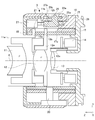
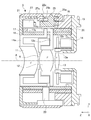
- FIG. 3 and 4 are cross-sectional views of the lens barrel 3.
- FIG. 3 shows a state where an image can be focused on the imaging surface of the imaging unit
- FIG. 4 shows a state where the image cannot be focused on the imaging surface. .
- the lens barrel 3 is mounted on the camera body 2 with a mount portion 15, a fixed barrel 16 fixed on the front side (Z plus side) of the mount portion 15, and a fixed barrel 16.
- a zoom ring 21 that can rotate is provided.
- the zoom ring 21 has a cylindrical shape that forms the outer shape of the lens barrel 3, and the lens barrel 3 expands and contracts by rotating the zoom ring 21.
- a rectilinear key 17 and a cam cylinder 18 are arranged inside the zoom ring 21 and the fixed cylinder 16.
- the lens barrel 3 is further arranged in order along the optical axis A so that the first lens group 11, the second lens group 12, and the third lens group 13 are directed from the subject side to the image side.
- These lens groups 11, 12, and 13 are held by lens frames 11a, 12a, and 13a, respectively.
- the first lens group 11 and the second lens group 12 function as a zoom lens.
- Cam pins 11 b and 12 b are connected to the lens frame 11 a of the first lens group 11 and the lens frame 12 a of the second lens group 12.
- the cam pins 11b and 12b are engaged with the cam cylinder 18 and the straight advance key 17, and move along the optical axis A by rotational power when the zoom ring 21 is rotated.
- the first lens group 11 and the second lens group 12 move linearly along the optical axis A.
- FIG. 2 shows a situation where the lens barrel 3 is in the TELE position (T).
- the zoom ring 21 can be rotated between the TELE position (T) and the WIDE position (W) shown in FIG. 2 (region ⁇ ).
- the zoom ring 21 is provided with a zoom ring interlocking unit 20 shown in FIGS.
- the third lens group 13 functions as a focus lens group.
- the lens frame 13a of the third lens group 13 is connected to the focus motor 14 by gear connection, and the third lens group 13 moves when the focus motor 14 is driven.
- the third lens group 13 using the focus motor 14 as a drive source is driven independently of the first lens group 11 and the second lens group 12.
- the zoom ring 21 is provided with a shortening switch 25 for shortening the lens barrel length of the lens barrel 3.
- the shortening switch 25 is inserted into a notch 22 a formed in the zoom ring 21. A part of the shortening switch 25 is exposed from the notch 22a, and a sliding operation to the shortening switch 25 is possible through the notch 22a.
- a spring (not shown) is disposed between the shortening switch 25 and the fixed cylinder 16, and the shortening switch 25 is always urged in the Z minus direction by this spring. That is, the shortening switch 25 is in the Z minus position shown in FIG. 1 in a state where the sliding operation is not performed.
- the shortening switch 25 has a first protrusion 25a and a second protrusion 25b.
- the first protrusion 25a is formed to protrude toward the camera body 2 (Z minus side) with respect to the shortening switch 25, and the second protrusion 25b is formed to protrude toward the subject side (Z plus side).
- a cam groove 26 is formed in the fixed cylinder 16 with respect to the first protrusion 25a, and a solenoid 27 is disposed with respect to the second protrusion 25b.
- the cam groove 26 of the fixed cylinder 16 includes an abutting portion 26a, a V-groove portion 26b, and a lock groove portion 26c in this order along the rotation direction E of the main body portion 22 of the zoom ring 21.
- the abutment portion 26a is where the first projection 25a abuts, and the rotation of the zoom ring 21 is stopped by the abutment of the first projection 25a.
- the V-groove portion 26b is a portion to which the first protrusion 25a moves when the lens barrel 3 is shortened.
- the lock groove portion 26c locks the lens barrel 3 in a shortened state when the first protrusion 25a is fitted.
- the solenoid 27 is fixed inside the zoom ring 21, and its pin portion 27 a faces the second protrusion 25 b of the shortening switch 25.
- the pin portion 27a is in the extended state, the second protrusion 25b comes into contact, and thereby the rotation operation of the zoom ring 21 is stopped.
- the pin portion 27a is in the shortened state, the second protrusion 25b does not come into contact, and the rotation operation to the zoom ring 21 is possible.
- the drive of the solenoid 27 is controlled by a control unit (not shown).
- the lens barrel 3 of the present embodiment is further provided with detection means 31. Although specific locations of the detecting means 31 are not shown, as shown in FIGS. 5 to 10 (b), each has a fixed terminal 31a and a movable terminal 31b. A movable terminal 31 b is provided on the zoom ring 21. The fixed terminal 31a is provided with a brush (not shown) extending in the direction of the movable terminal 31b, and detects an operation to the shortening switch 25 when the brush contacts or is not in contact with the movable terminal 31b. ing. A detection signal detected by the detection means 31 is output to a control unit (not shown).
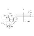
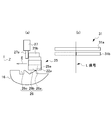
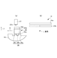
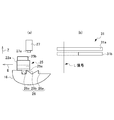
- FIGS. (A) in each of FIGS. 5 to 10 shows the operation of the shortening switch 25, and (b) shows the operation of the detecting means 31 at that time.
- An arrow E indicates the rotation direction of the zoom ring 21 including the main body 22.
- the in-focus area ⁇ from the T position to the W position and the in-focus area ⁇ with the W position as a boundary cannot be focused. It moves between shortened areas ⁇ , which are areas.
- FIG. 5 shows a state where the zoom ring 21 is rotated in the direction of arrow E to reach the W end (FIG. 2) from the T position.
- the first lens group 11 and the second lens group 12 move in the shortening direction (Z minus direction).
- the shortening switch 25 is also rotated integrally by the rotation of the zoom ring 21 and moves in the direction of arrow E.
- the first protrusion 25a of the shortening switch 25 contacts the contact portion 26a formed on the fixed cylinder 16, and the entire rotation of the shortening switch 25 and the zoom ring 21 is restricted.
- the detection means 31 since the detection means 31 has not detected the movement of the movable terminal 31b, it is an H signal.
- the zoom ring 21 does not rotate any more. For this reason, the movement of the first lens group 11 and the second lens group 12 constituting the zoom lens group in the shortening direction (Z minus direction) stops, and these lens groups 11 and 12 (second lens group 12) There is no collision with the third lens group 13 constituting the focus lens group.
- the zoom ring 21 After the rotation of the zoom ring 21 stops, as shown in FIG. 6, the operator slides the shortening switch 25 in the Z plus direction. Since the first protrusion 25a is detached from the contact with the contact portion 26a by this sliding operation, the zoom ring 21 can be rotated in the direction of arrow E. Even at this time, the signal from the detection means 31 is an H signal that does not detect the movable terminal 31b.
- FIG. 7 shows a state where the zoom switch 21 is slightly rotated in the E direction by sliding the shortening switch 25 with respect to the state of FIG.
- the detection means 31 outputs an L signal to the control unit.
- the control unit controls the focus motor 14 to start rotation of the motor 14.
- the third lens group 13 moves in the shortening direction (Z minus direction) along the optical axis A direction.
- the zoom ring 21 is in a rotation restricted state in which the rotation is stopped. Since the rotation of the zoom ring 21 is restricted, the movement of the first lens group 11 and the second lens group 12 is stopped. Accordingly, only the third lens group 13 moves in the shortening direction in advance.
- the third lens group 13 is retracted to the shortened position shown in FIG. 4, and after the retract is completed, the rotation of the focus motor 14 is stopped.
- the solenoid 27 is shortened by the control of the control unit.
- the pin portion 27a is retracted. If the zoom ring 21 is rotated back in the reverse direction in the state of FIG. 7, the signal of the detection means 31 becomes an H signal, so that the solenoid 27 is extended and the pin portion 27a and the second protrusion 25b Abut.
- FIG. 8 shows a state where the solenoid 27 is shortened and the rotation restriction is released.
- the zoom ring 21 can be further rotated in the direction of arrow E from the W position (FIG. 2), and the zoom ring 21 rotates in the shortened region ⁇ shown in FIG.
- the first lens group 11 and the second lens group 12 move in the shortening direction along the optical axis A by the rotation of the zoom ring 21 in the direction of the arrow E in the shortening region ⁇ .
- the third lens group 13 has already retracted to the position of the contraction cylinder, so that these lens groups 11 and 12 do not collide with the third lens group 13. Absent.
- the shortening switch 25 moves over the contact part 26a to a position facing the V groove part 26b.
- FIG. 9 shows the progress of the process from FIG. 8 to FIG.
- the shortening switch 25 when the operating force to the shortening switch 25 is released, the shortening switch 25 is biased so as to return to the initial position (FIG. 1) by the spring, so that the first protrusion 25a is placed in the V groove portion 26b. Get in.
- the lens rotates and is not suitable for lens replacement.
- FIG. 10 shows a state in which the zoom ring 21 is rotated to the contracted cylinder position.
- the first projection 25a of the shortening switch 25 moves while sliding on the slope of the V-groove portion 26b, passes through the V-groove portion 26b, and the lock groove portion 26c.
- the shortening switch 25 is biased by a spring, the first protrusion 25a is fitted into the lock groove portion 26c.
- FIG. 4 shows a state in which the lens barrel 3 corresponding to FIG. 10 is contracted.
- the shortening switch 25 is slid in the Z minus direction. Since the zoom ring 21 is unlocked by this sliding movement, the zoom ring 21 can be rotated in the direction opposite to the arrow E, and the lens groups 11, 12, and 13 can be moved to the focusable region.
- the present embodiment has the following effects. (1) By rotating the zoom ring 21 in the focusable area ⁇ , the first lens group 11 and the second lens group 12 move in the shortening direction, but the focusable area ⁇ and the non-focusable area ( Since the shortening switch 25 comes into contact with the contact portion 26a at the boundary (shortening region) ⁇ (W position in FIG. 2), the rotation of the zoom ring 21 is stopped. Thereby, the movement in the further shortening direction of the 1st lens group 11 and the 2nd lens group 12 is restrict
- the encoder structure is provided with the fixed terminal 31a and the movable terminal 31b as the detecting means 31 for detecting the sliding operation to the shortening switch 25.
- the present invention is not limited to this. It may be a structure to detect automatically.
- the detection means 31 may have a structure in which a convex portion is provided in the slide region of the shortening switch 25 and detects that the shortening switch 25 gets over the convex portion.
- the present invention is not limited to this, and the present invention can be similarly applied to a mobile phone having an imaging function. Note that the embodiment and the modification can be combined as appropriate, but detailed description thereof is omitted. Further, the present invention is not limited to the embodiment described above.
Landscapes
- Physics & Mathematics (AREA)
- General Physics & Mathematics (AREA)
- Engineering & Computer Science (AREA)
- General Engineering & Computer Science (AREA)
- Optics & Photonics (AREA)
- Lens Barrels (AREA)
Abstract
レンズ鏡筒の長さを短縮する際に、レンズ同士の衝突を回避可能なレンズ鏡筒及び撮像装置を提供する。 本発明のレンズ鏡筒は、複数のレンズからなる光学系内の物体側に配置されるとともに、前記光学系の光軸方向に沿った前記複数のレンズの間隔が所定間隔である第1の状態と該第1の状態に対して前記複数のレンズの間隔が狭い第2状態とに変更可能な第1レンズ群と、前記第1レンズ群より前記光学系内の像側に配置されるとともに、前記光学系の光軸に沿って移動することにより前記光学系の結像状態を変更可能な第2レンズ群と、前記第1レンズ群の前記第1の状態から前記第2の状態への変更を制限する制限部材と、前記制限部材によって前記第2状態への変更が制限された状態で前記第2レンズ群を前記光学系の像側へ移動させる駆動手段と、を備え、前記制限部材は、前記駆動手段による前記第2レンズ群の移動の終了に応じて前記制限を解除することを特徴とする。
Description
本発明は、レンズ鏡筒及びそれを備えた撮像装置に関するものである。
従来、ズームレンズ鏡筒の携帯性や不使用時の収納性を向上させるために、レンズの間隔を狭めてレンズ鏡筒長を縮めることが可能なレンズ鏡筒が知られている(例えば、特許文献1参照)。
しかし、フォーカスレンズがズームレンズよりも像側に配置されているレンズ鏡筒において、ズームレンズを後退させて鏡筒長を短縮する構成では、フォーカスレンズが光学系の物体側に位置していると、鏡筒長を短縮する際にズームレンズとフォーカスレンズとが衝突する可能性がある。
本発明の課題は、レンズ鏡筒の長さを短縮する際に、レンズ同士の衝突を回避可能なレンズ鏡筒及び撮像装置を提供することである。
本発明は、以下のような解決手段により前記課題を解決する。
請求項1に記載の発明は、複数のレンズからなる光学系内の物体側に配置されるとともに、前記光学系の光軸方向に沿った前記複数のレンズの間隔が所定間隔である第1の状態と該第1の状態に対して前記複数のレンズの間隔が狭い第2状態とに変更可能な第1レンズ群と前記第1レンズ群より前記光学系内の像側に配置されるとともに、前記光学系の光軸に沿って移動することにより前記光学系の結像状態を変更可能な第2レンズ群と前記第1レンズ群の前記第1の状態から前記第2の状態への変更を制限する制限部材と前記制限部材によって前記第2状態への変更が制限された状態で前記第2レンズ群を前記光学系の像側へ移動させる駆動手段と、を備え前記制限部材は、前記駆動手段による前記第2レンズ群の移動の終了に応じて前記制限を解除することを特徴とするレンズ鏡筒である。
請求項2に記載の発明は、請求項1に記載のレンズ鏡筒であって操作されることにより、前記第1レンズ群を前記第1状態から前記第2状態に変更する第1操作部材と前記第1操作部材による前記変更が前記制限部材によって制限された状態で操作されることにより、前記駆動手段を起動して前記第2レンズ群を移動する第2操作部材と、を備えたことを特徴とするレンズ鏡筒である。
請求項3に記載の発明は、請求項2に記載のレンズ鏡筒であって前記第1操作部材は、前記光学系の光軸周りの第1方向に回動することにより前記第1レンズ群を前記第1の状態から前記第2の状態に変更するものであり前記第2操作部材は、前記制限部材に当接可能な係合部を有することにより、前記第1操作部材の前記第1方向への回動を制限可能とすること、を特徴とするレンズ鏡筒である。
請求項4に記載の発明は、請求項3に記載のレンズ鏡筒であって前記駆動手段は、前記第2操作部材を前記第1方向と異なる第2方向へ操作することによる、前記係合部と前記制限部材との係合の解除に応じて、前記第2レンズ群を駆動すること、を特徴とするレンズ鏡筒である。
請求項5に記載の発明は、請求項3又は4に記載のレンズ鏡筒であって前記制限部材は、前記係合部と当接可能な第1制限部材と、該第1制限部材と前記係合部との当接位置に対して前記第1方向に変位して配置された第2の制限部材とを備えること、を特徴とするレンズ鏡筒である。
請求項6に記載の発明は、請求項5に記載のレンズ鏡筒であって前記第2操作部材の前記第2方向の操作により、前記係合部と前記第1の制限部材との係合が解除可能で前記係合部は、前記第1の制限部材との係合が解除された後に、前記第2の制限部材と係合すること、を特徴とするレンズ鏡筒である。
請求項7に記載の発明は、請求項6に記載のレンズ鏡筒であって前記第2レンズ群の前記像側への移動が終了したことに応じて、前記係合部と前記第2の制限部材との係合が解除されること、を特徴とするレンズ鏡筒である。
請求項8に記載の発明は、請求項7に記載のレンズ鏡筒であって前記第2の制限部材との係合が解除された後に前記係合部が係合することにより、前記第1操作部材の前記第1方向への回動を規制する規制部を有すること、を特徴とするレンズ鏡筒である。
請求項9に記載の発明は、請求項1~8のいずれか1項に記載のレンズ鏡筒を備える撮像装置である。
なお、上記説明した構成は、適宜改良してもよく、また、少なくとも一部を他の構成物に代替してもよい。
請求項2に記載の発明は、請求項1に記載のレンズ鏡筒であって操作されることにより、前記第1レンズ群を前記第1状態から前記第2状態に変更する第1操作部材と前記第1操作部材による前記変更が前記制限部材によって制限された状態で操作されることにより、前記駆動手段を起動して前記第2レンズ群を移動する第2操作部材と、を備えたことを特徴とするレンズ鏡筒である。
請求項3に記載の発明は、請求項2に記載のレンズ鏡筒であって前記第1操作部材は、前記光学系の光軸周りの第1方向に回動することにより前記第1レンズ群を前記第1の状態から前記第2の状態に変更するものであり前記第2操作部材は、前記制限部材に当接可能な係合部を有することにより、前記第1操作部材の前記第1方向への回動を制限可能とすること、を特徴とするレンズ鏡筒である。
請求項4に記載の発明は、請求項3に記載のレンズ鏡筒であって前記駆動手段は、前記第2操作部材を前記第1方向と異なる第2方向へ操作することによる、前記係合部と前記制限部材との係合の解除に応じて、前記第2レンズ群を駆動すること、を特徴とするレンズ鏡筒である。
請求項5に記載の発明は、請求項3又は4に記載のレンズ鏡筒であって前記制限部材は、前記係合部と当接可能な第1制限部材と、該第1制限部材と前記係合部との当接位置に対して前記第1方向に変位して配置された第2の制限部材とを備えること、を特徴とするレンズ鏡筒である。
請求項6に記載の発明は、請求項5に記載のレンズ鏡筒であって前記第2操作部材の前記第2方向の操作により、前記係合部と前記第1の制限部材との係合が解除可能で前記係合部は、前記第1の制限部材との係合が解除された後に、前記第2の制限部材と係合すること、を特徴とするレンズ鏡筒である。
請求項7に記載の発明は、請求項6に記載のレンズ鏡筒であって前記第2レンズ群の前記像側への移動が終了したことに応じて、前記係合部と前記第2の制限部材との係合が解除されること、を特徴とするレンズ鏡筒である。
請求項8に記載の発明は、請求項7に記載のレンズ鏡筒であって前記第2の制限部材との係合が解除された後に前記係合部が係合することにより、前記第1操作部材の前記第1方向への回動を規制する規制部を有すること、を特徴とするレンズ鏡筒である。
請求項9に記載の発明は、請求項1~8のいずれか1項に記載のレンズ鏡筒を備える撮像装置である。
なお、上記説明した構成は、適宜改良してもよく、また、少なくとも一部を他の構成物に代替してもよい。
本発明によれば、レンズ鏡筒の長さを短縮する際に、レンズ同士の衝突を回避可能なレンズ鏡筒及び撮像装置を提供することができる。
以下、図面等を参照して、本発明の実施形態について説明する。なお、以下に示す各図には、説明と理解を容易にするために、XYZ直交座標系を設けた。この座標系では、撮影者が光軸Aを水平として横長の画像を撮影する場合のカメラの位置(以下、正位置という)において撮影者から見て左側に向かう方向をXプラス方向とする。また、正位置において上側に向かう方向をYプラス方向とする。さらに、正位置において被写体に向かう方向をZプラス方向とする。
図1及び図2は、本発明の一実施形態が適用されたレンズ交換式のカメラ1を示す。カメラ1は、カメラ本体2と、カメラ本体2の前面に着脱可能に装着されるレンズ鏡筒3とを備えており、レンズ鏡筒3はカメラ本体2に対して交換可能な交換レンズとなっている。
カメラ本体2は、いずれも図示を省略したミラーユニット、シャッタ、撮像部、液晶表示パネル、ファインダ、及び各種の制御を行う制御部等を有している。図1に示すように、カメラ本体2の上面には、撮影の際に押圧操作されるレリーズ釦4が配置されている。また、図2に示すように、カメラ本体2の前面におけるレンズ鏡筒3に近接した位置には、レンズ着脱釦5が配置されている。レンズ着脱釦5は、カメラ本体2に対してレンズ鏡筒3を着脱するための操作釦である。
図3及び図4は、レンズ鏡筒3の断面図を示し、図3は撮像部における撮像面に像を合焦可能な状態、図4は撮像面に像を合焦不可能な状態である。
図3及び図4に示すように、レンズ鏡筒3はカメラ本体2に取り付けるためのマウント部15と、マウント部15の前側(Zプラス側)に固定された固定筒16と、固定筒16に対して回転可能なズーム環21とを有している。ズーム環21は、レンズ鏡筒3の外形を形成する筒状となっており、ズーム環21を回転操作することによってレンズ鏡筒3が伸縮する。ズーム環21及び固定筒16の内部には、直進キー17及びカム筒18が配置されている。
レンズ鏡筒3は、さらに、第1レンズ群11、第2レンズ群12、第3レンズ群13が被写体側から像側に向かうように光軸Aに沿って順に配置されている。これらのレンズ群11,12,13は、それぞれレンズ枠11a,12a,13aに保持されている。
第1レンズ群11及び第2レンズ群12はズームレンズとして機能する。第1レンズ群11のレンズ枠11a及び第2レンズ群12のレンズ枠12aにはカムピン11b,12bが連結されている。カムピン11b,12bは、カム筒18及び直進キー17と係合しており、ズーム環21を回転操作する際の回転動力により光軸Aに沿って移動する。これにより、第1レンズ群11、第2レンズ群12は光軸Aに沿って直線的に移動する。
図2においてPは、ズーム環21の側面に形成された印であり、レンズ鏡筒3の現在の状態を示す。図2は、レンズ鏡筒3がTELE位置(T)にある状況を示している。合焦可能な状態において、ズーム環21は、図2で示すTELE位置(T)及びWIDE位置(W)の間(領域α)で回転操作可能となっている。この領域αでのズーム環21の回転操作により第1レンズ群11及び第2レンズ群12が光軸Aに沿って移動してズーム操作が行われる。なお、ズーム環21には、図3及び4に示すズーム環連動部20が設けられている。ズーム環21を回転させると、ズーム環連動部20によりカム筒18に回転が伝えられ、カム筒18の回転により、カム筒18に設けられたカム18a,18b及び直進キー17の直進溝17aに沿ってカムピン11b,12bが、光軸方向に直進し、第1レンズ群11及び第2レンズ群12は光軸A方向に移動することができる。
第3レンズ群13は、フォーカスレンズ群として機能する。第3レンズ群13のレンズ枠13aは、ギア連結によってフォーカスモータ14に連結されており、フォーカスモータ14が駆動することにより第3レンズ群13は移動する。フォーカスモータ14を駆動源とする第3レンズ群13は、第1レンズ群11及び第2レンズ群12とは独立して駆動される。
ズーム環21にはレンズ鏡筒3の鏡筒長を短縮状態とするための短縮スイッチ25が設けられている。短縮スイッチ25は、ズーム環21に形成された切欠部22aに挿入されている。短縮スイッチ25は、切欠部22aからその一部が露出しており、切欠部22aを通して短縮スイッチ25へのスライド操作が可能となっている。
短縮スイッチ25と固定筒16との間には、不図示のバネが配置されており、このバネによって短縮スイッチ25は常にZマイナス方向に付勢されている。すなわち、短縮スイッチ25はスライド操作が行われていない状態では、図1に示すZマイナス位置にある。
短縮スイッチ25は、第1突起25a及び第2突起25bを有している。第1突起25aは、短縮スイッチ25に対しカメラ本体2側(Zマイナス側)に突出するように形成され、第2突起25bは被写体側(Zプラス側)に突出するように形成されている。第1突起25aに対し固定筒16にはカム溝26が形成され、第2突起25bに対してはソレノイド27が配置されている。
固定筒16のカム溝26は図5~図10に示すように、ズーム環21の本体部22の回転方向Eに沿って当接部26a、V溝部26b、ロック溝部26cを順に備えている。当接部26aは、第1突起25aが当接するものであり、第1突起25aの当接によりズーム環21の回転が停止される。V溝部26bはレンズ鏡筒3の短縮状態において第1突起25aが移動する部分である。ロック溝部26cは第1突起25aが嵌入することによりレンズ鏡筒3を短縮状態にロックするものである。
ソレノイド27は図3及び図4に示すように、ズーム環21の内部に固定されており、そのピン部27aが短縮スイッチ25の第2突起25bに対向している。ピン部27aが伸長状態の場合には、第2突起25bが当接し、これにより、ズーム環21の回転操作が停止する。ピン部27aが短縮状態の場合には、第2突起25bが当接することがなく、ズーム環21への回転操作が可能である。ソレノイド27は不図示の制御部によってその駆動が制御されている。
本実施形態のレンズ鏡筒3は、さらに検知手段31が設けられている。なお、検知手段31の具体的な配置箇所は図示を省略するが、図5~図10のそれぞれの(b)に示すように、固定端子31aと可動端子31bとを有し、固定端子31aが固定筒16に設けられ、可動端子31bがズーム環21に設けられている。固定端子31aには、可動端子31b方向に延びる不図示のブラシが設けられており、ブラシが可動端子31bと接触したり、非接触となることにより短縮スイッチ25への操作を検出するようになっている。検知手段31が検出した検知信号は不図示の制御部に出力される。
次に、本実施形態における合焦可能な状態から合焦不可能な短縮状態への作動を図5~図10により説明する。図5~図10のそれぞれにおける(a)は、短縮スイッチ25の作動を示し、(b)はそのときの検知手段31の動作を示している。また、矢印Eは本体部22を含むズーム環21の回転方向を示す。図2に示すように、ズーム環21は回転操作を行うことにより、T位置からW位置までの合焦可能領域α及びW位置を境界として合焦可能領域αに連続している合焦不可能領域である短縮領域βの間を移動する。
図5は、ズーム環21を矢印E方向に回転させることによりT位置からW端(図2)に達した状態を示す。ズーム環21の回転によって第1レンズ群11及び第2レンズ群12は短縮方向(Zマイナス方向)に移動する。また、ズーム環21の回転により短縮スイッチ25も一体的に回転し、矢印E方向に移動する。この移動により、短縮スイッチ25の第1突起25aが固定筒16に形成された当接部26aに当接し、短縮スイッチ25及びズーム環21の全体の回転が制限される。この時点においては、検知手段31は可動端子31bの移動を検知していないため、H信号となっている。
このように短縮スイッチ25の第1突起25aが当接部26aに当接してズーム環21の回転が制限されるため、ズーム環21はそれ以上、回転することがない。このため、ズームレンズ群を構成する第1レンズ群11及び第2レンズ群12の短縮方向(Zマイナス方向)への移動が停止し、これらのレンズ群11,12(第2レンズ群12)は、フォーカスレンズ群を構成する第3レンズ群13とぶつかることがない。
ズーム環21の回転が停止した後においては、図6に示すように、操作者が短縮スイッチ25をZプラス方向にスライド操作させる。このスライド操作により第1突起25aが当接部26aとの当接から離脱するため、ズーム環21に対して矢印E方向への回転操作が可能となる。このときにおいても、検知手段31からの信号は可動端子31bを検知していないH信号となっている。
図7は、図6の状態に対し、短縮スイッチ25をスライド操作させてズーム環21をさらにE方向へわずかに回転させた状態を示す。可動端子31bがHとLとの境界となるラインを越え、検知手段31はL信号を制御部に出力する。制御部はL信号の入力により、フォーカスモータ14を制御して同モータ14の回転を開始する。フォーカスモータ14の回転により、第3レンズ群13が光軸A方向に沿って短縮方向(Zマイナス方向)に移動する。この動作中は、短縮スイッチ25の第2突起25bがソレノイド27のピン部27aに当接しているため、ズーム環21は回転が停止した回転規制状態となっている。ズーム環21が回転規制されているため、第1レンズ群11及び第2レンズ群12は移動が停止した状態となっている。従って、第3レンズ群13だけが先行して短縮方向に移動する。
フォーカスモータ14の駆動によって、第3レンズ群13は図4に示す短縮位置まで退避し、この退避が終了後、フォーカスモータ14の回転が停止する。フォーカスモータ14の回転の停止と同時に制御部の制御によってソレノイド27が短縮作動する。これによりピン部27aが退避する。なお、図7の状態でズーム環21を逆方向に回転させる回転戻しを行うと、検知手段31の信号がH信号となるため、ソレノイド27が伸長作動してピン部27aと第2突起25bとが当接する。
図8はソレノイド27が短縮して回転規制が解除された状態を示している。この状態では、W位置(図2)から、さらにズーム環21の矢印E方向への回転が可能となり、ズーム環21は図2で示す短縮領域βで回転する。この短縮領域βでのズーム環21の矢印E方向への回転によって、第1レンズ群11及び第2レンズ群12は光軸Aに沿って短縮方向に移動する。これらのレンズ群11,12が短縮方向に移動しても、第3レンズ群13は既に縮筒位置まで退避しているため、これらのレンズ群11,12が第3レンズ群13とぶつかることはない。図8において、ズーム環21を回転させることにより、短縮スイッチ25は当接部26aを乗り越えてV溝部26bに臨んだ位置まで移動する。
図9は、図8から図9に達するまでの途中経過を示している。図9の状態で、短縮スイッチ25への操作力を解除すると、短縮スイッチ25がバネにより初期位置(図1)に戻るように付勢されているため、第1突起25aがV溝部26b内に入り込む。この状態では、短縮スイッチ25の第1突起25aがV溝部26b内にあるため、レンズが回転し、レンズ交換には適していない。
図10は、ズーム環21を縮筒位置まで回転させた状態を示している。ズーム環21を図9の状態よりもさらに矢印E方向に回転させることにより、短縮スイッチ25の第1突起25aはV溝部26bの斜面を滑りながら移動してV溝部26bを通過し、ロック溝部26cに達する。短縮スイッチ25はバネによって付勢されているため、第1突起25aがロック溝部26cに嵌入する。この嵌入によりズーム環21の回転が確実にロックされる。従って、レンズ着脱釦5を操作して、レンズ鏡筒3をカメラ本体2から取り外すレンズ交換が可能となる。図4は、図10に対応したレンズ鏡筒3を縮筒させた状態を示す。
一方、図4及び図10の短縮状態から合焦可能領域にレンズ群を移動させるには、短縮スイッチ25をZマイナス方向にスライド移動させる。このスライド移動によってズーム環21のロックが解除されるため、ズーム環21を矢印Eと反対方向に回転させることができ、レンズ群11,12,13を合焦可能領域に移動させることができる。
以上、本実施形態によると、以下の効果を有する。
(1)合焦可能領域αでズーム環21を回転操作することにより、第1レンズ群11及び第2レンズ群12が短縮方向に移動するが、合焦可能領域αと合焦不可能領域(短縮領域)βとの境界(図2におけるW位置)では短縮スイッチ25が当接部26aに当接するため、ズーム環21の回転が停止する。これにより、第1レンズ群11及び第2レンズ群12のそれ以上の短縮方向への移動が制限される。このため、第1レンズ群11及び第2レンズ群12が第3レンズ群13とぶつかることがない。
(1)合焦可能領域αでズーム環21を回転操作することにより、第1レンズ群11及び第2レンズ群12が短縮方向に移動するが、合焦可能領域αと合焦不可能領域(短縮領域)βとの境界(図2におけるW位置)では短縮スイッチ25が当接部26aに当接するため、ズーム環21の回転が停止する。これにより、第1レンズ群11及び第2レンズ群12のそれ以上の短縮方向への移動が制限される。このため、第1レンズ群11及び第2レンズ群12が第3レンズ群13とぶつかることがない。
(2)合焦可能領域αと合焦不可能領域βとの境界では、短縮スイッチ25を操作することにより、第3レンズ群13が先行して短縮位置に退避する。また、このときには短縮スイッチ25がソレノイド27のピン部27aに当接しているため、ズーム環21の回転が制限されており、第1レンズ群11及び第2レンズ群12が短縮方向に移動することがない。このため、短縮領域βにおいても、第1レンズ群11及び第2レンズ群12が第3レンズ群13とぶつかることがない。
(変形形態)
以上、説明した実施形態に限定されることなく、以下に示すような種々の変形や変更が可能であり、それらも本発明の範囲内である。
(1)本実施形態では、短縮スイッチ25へのスライド操作を検出する検知手段31として固定端子31a及び可動端子31bを備えたエンコーダ構造としているが、これに限らず、短縮スイッチ25のスライドを光学的に検知する構造であってもよい。
(2)検知手段31としては、短縮スイッチ25のスライド領域に凸部を設け、短縮スイッチ25が凸部を乗り越えることを検知する構造であってもよい。
(3)本実施形態では、カメラへの適用を説明しているが、これに限らず、撮像機能を有している携帯電話機等にも同様に適用することができる。
なお、実施形態及び変形形態は、適宜組み合わせて用いることもできるが、詳細な説明は省略する。また、本発明は以上説明した実施形態によって限定されることはない。
以上、説明した実施形態に限定されることなく、以下に示すような種々の変形や変更が可能であり、それらも本発明の範囲内である。
(1)本実施形態では、短縮スイッチ25へのスライド操作を検出する検知手段31として固定端子31a及び可動端子31bを備えたエンコーダ構造としているが、これに限らず、短縮スイッチ25のスライドを光学的に検知する構造であってもよい。
(2)検知手段31としては、短縮スイッチ25のスライド領域に凸部を設け、短縮スイッチ25が凸部を乗り越えることを検知する構造であってもよい。
(3)本実施形態では、カメラへの適用を説明しているが、これに限らず、撮像機能を有している携帯電話機等にも同様に適用することができる。
なお、実施形態及び変形形態は、適宜組み合わせて用いることもできるが、詳細な説明は省略する。また、本発明は以上説明した実施形態によって限定されることはない。
1:カメラ、3:レンズ鏡筒、11:第1レンズ群、12:第2レンズ群、13:第3レンズ群、21:ズーム環、25:短縮スイッチ、25a:第1突起、25b:第2突起、26:カム溝、26a:当接部、26b:V溝部、26c:ロック溝部、27:ソレノイド、31:検知手段
Claims (9)
- 複数のレンズからなる光学系内の物体側に配置されるとともに、前記光学系の光軸方向に沿った前記複数のレンズの間隔が所定間隔である第1の状態と該第1の状態に対して前記複数のレンズの間隔が狭い第2状態とに変更可能な第1レンズ群と、
前記第1レンズ群より前記光学系内の像側に配置されるとともに、前記光学系の光軸に沿って移動することにより前記光学系の結像状態を変更可能な第2レンズ群と、
前記第1レンズ群の前記第1の状態から前記第2の状態への変更を制限する制限部材と、
前記制限部材によって前記第2状態への変更が制限された状態で前記第2レンズ群を前記光学系の像側へ移動させる駆動手段と、を備え、
前記制限部材は、前記駆動手段による前記第2レンズ群の移動の終了に応じて前記制限を解除することを特徴とするレンズ鏡筒。 - 請求項1に記載のレンズ鏡筒であって、
操作されることにより、前記第1レンズ群を前記第1状態から前記第2状態に変更する第1操作部材と、
前記第1操作部材による前記変更が前記制限部材によって制限された状態で操作されることにより、前記駆動手段を起動して前記第2レンズ群を移動する第2操作部材と、
を備えたことを特徴とするレンズ鏡筒。 - 請求項2に記載のレンズ鏡筒であって、
前記第1操作部材は、前記光学系の光軸周りの第1方向に回動することにより前記第1レンズ群を前記第1の状態から前記第2の状態に変更するものであり、
前記第2操作部材は、前記制限部材に当接可能な係合部を有することにより、前記第1操作部材の前記第1方向への回動を制限可能とすること、
を特徴とするレンズ鏡筒。 - 請求項3に記載のレンズ鏡筒であって、
前記駆動手段は、前記第2操作部材を前記第1方向と異なる第2方向へ操作することによる、前記係合部と前記制限部材との係合の解除に応じて、前記第2レンズ群を駆動すること、
を特徴とするレンズ鏡筒。 - 請求項3又は4に記載のレンズ鏡筒であって、
前記制限部材は、前記係合部と当接可能な第1制限部材と、該第1制限部材と前記係合部との当接位置に対して前記第1方向に変位して配置された第2の制限部材とを備えること、
を特徴とするレンズ鏡筒。 - 請求項5に記載のレンズ鏡筒であって、
前記第2操作部材の前記第2方向の操作により、前記係合部と前記第1の制限部材との係合が解除可能で、
前記係合部は、前記第1の制限部材との係合が解除された後に、前記第2の制限部材と係合すること、
を特徴とするレンズ鏡筒。 - 請求項6に記載のレンズ鏡筒であって、
前記第2レンズ群の前記像側への移動が終了したことに応じて、前記係合部と前記第2の制限部材との係合が解除されること、
を特徴とするレンズ鏡筒。 - 請求項7に記載のレンズ鏡筒であって、
前記第2の制限部材との係合が解除された後に前記係合部が係合することにより、前記第1操作部材の前記第1方向への回動を規制する規制部を有すること、
を特徴とするレンズ鏡筒。 - 請求項1~8のいずれか1項に記載のレンズ鏡筒を備える撮像装置。
Priority Applications (1)
| Application Number | Priority Date | Filing Date | Title |
|---|---|---|---|
| US13/126,939 US8928994B2 (en) | 2008-11-07 | 2009-11-05 | Lens barrel and imaging device |
Applications Claiming Priority (2)
| Application Number | Priority Date | Filing Date | Title |
|---|---|---|---|
| JP2008286929A JP5245735B2 (ja) | 2008-11-07 | 2008-11-07 | レンズ鏡筒及び撮像装置 |
| JP2008-286929 | 2008-11-07 |
Publications (1)
| Publication Number | Publication Date |
|---|---|
| WO2010052910A1 true WO2010052910A1 (ja) | 2010-05-14 |
Family
ID=42152723
Family Applications (1)
| Application Number | Title | Priority Date | Filing Date |
|---|---|---|---|
| PCT/JP2009/005882 Ceased WO2010052910A1 (ja) | 2008-11-07 | 2009-11-05 | レンズ鏡筒及び撮像装置 |
Country Status (3)
| Country | Link |
|---|---|
| US (1) | US8928994B2 (ja) |
| JP (1) | JP5245735B2 (ja) |
| WO (1) | WO2010052910A1 (ja) |
Cited By (1)
| Publication number | Priority date | Publication date | Assignee | Title |
|---|---|---|---|---|
| US20120162781A1 (en) * | 2010-12-28 | 2012-06-28 | Canon Kabushiki Kaisha | Lens apparatus and image pickup system including the same |
Families Citing this family (4)
| Publication number | Priority date | Publication date | Assignee | Title |
|---|---|---|---|---|
| JP6004223B2 (ja) * | 2011-08-01 | 2016-10-05 | パナソニックIpマネジメント株式会社 | レンズ鏡筒および撮像装置 |
| JP6296894B2 (ja) * | 2014-05-14 | 2018-03-20 | キヤノン株式会社 | 電子機器 |
| JP2019095487A (ja) * | 2017-11-17 | 2019-06-20 | エスゼット ディージェイアイ テクノロジー カンパニー リミテッドSz Dji Technology Co.,Ltd | レンズ装置、撮像装置、及び移動体 |
| JP7277185B2 (ja) * | 2019-03-07 | 2023-05-18 | キヤノン株式会社 | 中間アダプタを装着可能なレンズ装置 |
Citations (3)
| Publication number | Priority date | Publication date | Assignee | Title |
|---|---|---|---|---|
| JP2001264616A (ja) * | 2000-03-22 | 2001-09-26 | Fuji Photo Optical Co Ltd | レンズ装置 |
| JP2002202547A (ja) * | 2000-10-31 | 2002-07-19 | Olympus Optical Co Ltd | バリア付きカメラ |
| JP2006091386A (ja) * | 2004-09-22 | 2006-04-06 | Nikon Corp | カメラ |
Family Cites Families (3)
| Publication number | Priority date | Publication date | Assignee | Title |
|---|---|---|---|---|
| JPH0225815A (ja) | 1988-07-15 | 1990-01-29 | Nikon Corp | 沈胴収納式交換ズームレンズ鏡筒 |
| JP4599676B2 (ja) * | 2000-07-13 | 2010-12-15 | 株式会社ニコン | レンズ鏡筒 |
| JP2009217014A (ja) * | 2008-03-11 | 2009-09-24 | Canon Inc | レンズ鏡筒および撮影装置 |
-
2008
- 2008-11-07 JP JP2008286929A patent/JP5245735B2/ja active Active
-
2009
- 2009-11-05 WO PCT/JP2009/005882 patent/WO2010052910A1/ja not_active Ceased
- 2009-11-05 US US13/126,939 patent/US8928994B2/en not_active Expired - Fee Related
Patent Citations (3)
| Publication number | Priority date | Publication date | Assignee | Title |
|---|---|---|---|---|
| JP2001264616A (ja) * | 2000-03-22 | 2001-09-26 | Fuji Photo Optical Co Ltd | レンズ装置 |
| JP2002202547A (ja) * | 2000-10-31 | 2002-07-19 | Olympus Optical Co Ltd | バリア付きカメラ |
| JP2006091386A (ja) * | 2004-09-22 | 2006-04-06 | Nikon Corp | カメラ |
Cited By (2)
| Publication number | Priority date | Publication date | Assignee | Title |
|---|---|---|---|---|
| US20120162781A1 (en) * | 2010-12-28 | 2012-06-28 | Canon Kabushiki Kaisha | Lens apparatus and image pickup system including the same |
| US8643956B2 (en) * | 2010-12-28 | 2014-02-04 | Canon Kabushiki Kaisha | Lens apparatus and image pickup system including the same |
Also Published As
| Publication number | Publication date |
|---|---|
| US8928994B2 (en) | 2015-01-06 |
| JP2010113238A (ja) | 2010-05-20 |
| JP5245735B2 (ja) | 2013-07-24 |
| US20110286110A1 (en) | 2011-11-24 |
Similar Documents
| Publication | Publication Date | Title |
|---|---|---|
| CN101750717B (zh) | 光学元件驱动机构和具有该光学元件驱动机构的摄像设备 | |
| JP6027811B2 (ja) | レンズ鏡筒 | |
| JP4599676B2 (ja) | レンズ鏡筒 | |
| EP1918771B1 (en) | Camera being equipped with a projector | |
| JP5446154B2 (ja) | レンズ鏡筒、光学機器 | |
| JP4775010B2 (ja) | レンズ鏡筒及びカメラ | |
| JP5245735B2 (ja) | レンズ鏡筒及び撮像装置 | |
| JPH11211965A (ja) | ズームレンズ鏡筒 | |
| US6992836B2 (en) | Lens barrel having cam-cylinder with cam-groove and varying wall thickness, lens barrel having guide-cylinder with varying wall thickness, and lens barrel having the cam-cylinder and the guide-cylinder | |
| JP5388521B2 (ja) | 撮像装置 | |
| JP6272047B2 (ja) | 光学機器 | |
| JP4420597B2 (ja) | 撮像装置 | |
| JP2002350709A (ja) | ズームカメラ | |
| JP2005172953A (ja) | レンズ鏡筒およびカメラ | |
| JP2025089610A (ja) | レンズ装置および撮像システム | |
| JP5125999B2 (ja) | レンズ鏡筒及びそれを備えた撮像装置 | |
| JP5754949B2 (ja) | ズームレンズ鏡筒およびデジタルカメラ | |
| JP4695969B2 (ja) | 鏡筒装置及び撮像装置 | |
| JP7721361B2 (ja) | 光学機器、レンズ鏡筒及び撮像装置 | |
| CN107102418B (zh) | 设置于摄像设备的镜筒和摄像设备 | |
| JP5428385B2 (ja) | レンズ鏡筒および撮像装置 | |
| JP5332470B2 (ja) | レンズ鏡筒、撮像装置 | |
| JP2019179052A (ja) | 像ブレ補正装置及び光学機器 | |
| JP2006284869A (ja) | レンズ鏡筒及びレンズユニット | |
| JP2011227328A (ja) | レンズ鏡筒及び撮影装置 |
Legal Events
| Date | Code | Title | Description |
|---|---|---|---|
| 121 | Ep: the epo has been informed by wipo that ep was designated in this application |
Ref document number: 09824610 Country of ref document: EP Kind code of ref document: A1 |
|
| NENP | Non-entry into the national phase |
Ref country code: DE |
|
| WWE | Wipo information: entry into national phase |
Ref document number: 13126939 Country of ref document: US |
|
| 122 | Ep: pct application non-entry in european phase |
Ref document number: 09824610 Country of ref document: EP Kind code of ref document: A1 |