WO2010052881A1 - Outil électrique - Google Patents
Outil électrique Download PDFInfo
- Publication number
- WO2010052881A1 WO2010052881A1 PCT/JP2009/005811 JP2009005811W WO2010052881A1 WO 2010052881 A1 WO2010052881 A1 WO 2010052881A1 JP 2009005811 W JP2009005811 W JP 2009005811W WO 2010052881 A1 WO2010052881 A1 WO 2010052881A1
- Authority
- WO
- WIPO (PCT)
- Prior art keywords
- lock ring
- handle
- rotation
- connecting shaft
- flange
- Prior art date
Links
Images


Classifications
-
- B—PERFORMING OPERATIONS; TRANSPORTING
- B25—HAND TOOLS; PORTABLE POWER-DRIVEN TOOLS; MANIPULATORS
- B25F—COMBINATION OR MULTI-PURPOSE TOOLS NOT OTHERWISE PROVIDED FOR; DETAILS OR COMPONENTS OF PORTABLE POWER-DRIVEN TOOLS NOT PARTICULARLY RELATED TO THE OPERATIONS PERFORMED AND NOT OTHERWISE PROVIDED FOR
- B25F5/00—Details or components of portable power-driven tools not particularly related to the operations performed and not otherwise provided for
- B25F5/02—Construction of casings, bodies or handles
Definitions
- the present invention relates to an electric tool such as an electric drill provided with a handle at the rear end of a housing.
- Some electric tools such as electric drills are provided with a handle at the rear end of a housing provided with a motor, a speed reduction mechanism, and the like. That is, the handle is gripped by one hand and the housing is directly supported by the other hand, or the side handle provided on the housing is gripped to support the electric tool and perform operations such as drilling.
- the handle there are known a fixed type in which the handle is fixed at a fixed angle with respect to the housing as described in Patent Document 1, and a rotary type in which the handle can be rotated at a predetermined angle as described in Patent Document 2, respectively. It has been.
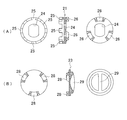
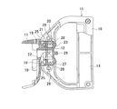
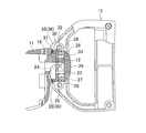
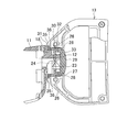
- the handle is rotatably connected by mounting the cylindrical portion on the connecting shaft in a state where a flange formed on the cylindrical portion is engaged with a concave groove formed on the connecting shaft. It is characterized by.
- the regulating means is A lock ring that is non-rotatably mounted on the connecting shaft in the cylindrical portion, and is slidable between a forward position engaged with the flange and a retracted position away from the flange; Biasing means for biasing the lock ring to the retracted position;
- the handle is provided behind the lock ring in the tubular portion so as to be rotatable, and the lock ring is slid to the advance position against the urging force of the urging means at the first rotation position.
Abstract
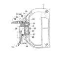
L'invention porte sur une poignée (13) reliée à l'extrémité arrière d'un boîtier (2) d'une perceuse électrique (1) de façon à pouvoir tourner autour d'un arbre de liaison (12), et la partie à laquelle la poignée (13) est reliée au boîtier (2) comporte un moyen de restriction (20) monté de telle sorte que la rotation de la poignée (13) peut être restreinte facultativement. Le moyen de restriction (20) comprend : une bague de verrouillage (21) montée dans une section tubulaire (15) sur l'arbre de liaison (12) de façon à ne pas pouvoir tourner mais de façon à pouvoir coulisser de la direction avant-arrière et à venir en prise avec une bride avant (18) à la position avancée vers l'avant ; un ressort enroulé (22) pour pousser la bague de verrouillage (21) vers la position rétractée vers l'arrière ; et une poignée d'actionnement (23), laquelle, à une première position de rotation, fait coulisser la bague de verrouillage (21) vers la position avancée vers l'avant pour restreindre la rotation de la poignée (13) et, à une seconde position de rotation, fait coulisser la bague de verrouillage (21) vers la position rétractée vers l'arrière afin de libérer la restriction sur la rotation de la poignée (13).
Applications Claiming Priority (2)
| Application Number | Priority Date | Filing Date | Title |
|---|---|---|---|
| JP2008283337A JP5319241B2 (ja) | 2008-11-04 | 2008-11-04 | 電動工具 |
| JP2008-283337 | 2008-11-04 |
Publications (1)
| Publication Number | Publication Date |
|---|---|
| WO2010052881A1 true WO2010052881A1 (fr) | 2010-05-14 |
Family
ID=42152695
Family Applications (1)
| Application Number | Title | Priority Date | Filing Date |
|---|---|---|---|
| PCT/JP2009/005811 WO2010052881A1 (fr) | 2008-11-04 | 2009-11-02 | Outil électrique |
Country Status (2)
| Country | Link |
|---|---|
| JP (1) | JP5319241B2 (fr) |
| WO (1) | WO2010052881A1 (fr) |
Cited By (1)
| Publication number | Priority date | Publication date | Assignee | Title |
|---|---|---|---|---|
| US9308638B2 (en) | 2013-01-17 | 2016-04-12 | Seiko Epson Corporation | Power tool and auxiliary handle member |
Citations (8)
| Publication number | Priority date | Publication date | Assignee | Title |
|---|---|---|---|---|
| JPS61100381A (ja) * | 1984-10-23 | 1986-05-19 | 松下電工株式会社 | 電動工具 |
| JPH03117573A (ja) * | 1989-09-08 | 1991-05-20 | Stihl Andreas | 手で案内される作業機械 |
| JPH0544477U (ja) * | 1991-11-26 | 1993-06-15 | 日立工機株式会社 | 回転ハンドル |
| JPH05508353A (ja) * | 1990-07-17 | 1993-11-25 | ローベルト ボツシユ ゲゼルシヤフト ミツト ベシユレンクテル ハフツング | 電気式の手持ち工作機械、特にアングルグラインダ |
| JPH06143119A (ja) * | 1992-11-06 | 1994-05-24 | Makita Corp | 携帯用回転工具 |
| JPH10313680A (ja) * | 1997-05-16 | 1998-12-02 | Kioritz Corp | 動力作業機用ハンドル装置 |
| JP2003260677A (ja) * | 2001-12-03 | 2003-09-16 | Milwaukee Electric Tool Corp | 往復動式のこぎりのハンドル装置 |
| JP2006035419A (ja) * | 2004-07-27 | 2006-02-09 | Hilti Ag | 手工具装置 |
-
2008
- 2008-11-04 JP JP2008283337A patent/JP5319241B2/ja not_active Expired - Fee Related
-
2009
- 2009-11-02 WO PCT/JP2009/005811 patent/WO2010052881A1/fr active Application Filing
Patent Citations (8)
| Publication number | Priority date | Publication date | Assignee | Title |
|---|---|---|---|---|
| JPS61100381A (ja) * | 1984-10-23 | 1986-05-19 | 松下電工株式会社 | 電動工具 |
| JPH03117573A (ja) * | 1989-09-08 | 1991-05-20 | Stihl Andreas | 手で案内される作業機械 |
| JPH05508353A (ja) * | 1990-07-17 | 1993-11-25 | ローベルト ボツシユ ゲゼルシヤフト ミツト ベシユレンクテル ハフツング | 電気式の手持ち工作機械、特にアングルグラインダ |
| JPH0544477U (ja) * | 1991-11-26 | 1993-06-15 | 日立工機株式会社 | 回転ハンドル |
| JPH06143119A (ja) * | 1992-11-06 | 1994-05-24 | Makita Corp | 携帯用回転工具 |
| JPH10313680A (ja) * | 1997-05-16 | 1998-12-02 | Kioritz Corp | 動力作業機用ハンドル装置 |
| JP2003260677A (ja) * | 2001-12-03 | 2003-09-16 | Milwaukee Electric Tool Corp | 往復動式のこぎりのハンドル装置 |
| JP2006035419A (ja) * | 2004-07-27 | 2006-02-09 | Hilti Ag | 手工具装置 |
Cited By (1)
| Publication number | Priority date | Publication date | Assignee | Title |
|---|---|---|---|---|
| US9308638B2 (en) | 2013-01-17 | 2016-04-12 | Seiko Epson Corporation | Power tool and auxiliary handle member |
Also Published As
| Publication number | Publication date |
|---|---|
| JP5319241B2 (ja) | 2013-10-16 |
| JP2010110834A (ja) | 2010-05-20 |
Similar Documents
| Publication | Publication Date | Title |
|---|---|---|
| JP4227028B2 (ja) | ドライバドリル | |
| US7314097B2 (en) | Hammer drill with a mode changeover mechanism | |
| US6142242A (en) | Percussion driver drill, and a changeover mechanism for changing over a plurality of operating modes of an apparatus | |
| US6488451B1 (en) | Drive shaft lock | |
| EP2008746B1 (fr) | Foreuse multi-vitesse et ensemble de mandrin | |
| JP5628079B2 (ja) | 震動ドライバドリル | |
| JP6746792B2 (ja) | トルク伝達方向変更機構 | |
| US7124839B2 (en) | Impact driver having an external mechanism which operation mode can be selectively switched between impact and drill modes | |
| US8057134B2 (en) | Chuck assembly | |
| CA2549989C (fr) | Tournevis avec mecanisme a rochet | |
| KR20040068965A (ko) | 드릴/드라이버 상의 측면 핸들 | |
| JP5462241B2 (ja) | 電動工具 | |
| JP5340881B2 (ja) | 打撃工具 | |
| US8931375B2 (en) | Ratchet device | |
| JP5415176B2 (ja) | スイッチ | |
| JP3955745B2 (ja) | アングルドリル | |
| JP4053865B2 (ja) | 電動工具 | |
| JP3655481B2 (ja) | 震動ドライバドリル | |
| SE529928C2 (sv) | Låsanordning för portabelt verktyg | |
| JP4767593B2 (ja) | 車両用イグニッションスイッチの操作装置 | |
| US6450312B1 (en) | Easily direction-convertible ratchet assembly for a hand tool | |
| JP5319241B2 (ja) | 電動工具 | |
| JP2005118961A (ja) | ドライバドリル | |
| JP2012006101A (ja) | 打撃工具 | |
| TWI696523B (zh) | 用於棘輪工具的換向機構 |
Legal Events
| Date | Code | Title | Description |
|---|---|---|---|
| 121 | Ep: the epo has been informed by wipo that ep was designated in this application |
Ref document number: 09824582 Country of ref document: EP Kind code of ref document: A1 |
|
| NENP | Non-entry into the national phase |
Ref country code: DE |
|
| 122 | Ep: pct application non-entry in european phase |
Ref document number: 09824582 Country of ref document: EP Kind code of ref document: A1 |