WO2010052881A1 - Electric tool - Google Patents
Electric tool Download PDFInfo
- Publication number
- WO2010052881A1 WO2010052881A1 PCT/JP2009/005811 JP2009005811W WO2010052881A1 WO 2010052881 A1 WO2010052881 A1 WO 2010052881A1 JP 2009005811 W JP2009005811 W JP 2009005811W WO 2010052881 A1 WO2010052881 A1 WO 2010052881A1
- Authority
- WO
- WIPO (PCT)
- Prior art keywords
- lock ring
- handle
- rotation
- connecting shaft
- flange
- Prior art date
Links
Images


Classifications
-
- B—PERFORMING OPERATIONS; TRANSPORTING
- B25—HAND TOOLS; PORTABLE POWER-DRIVEN TOOLS; MANIPULATORS
- B25F—COMBINATION OR MULTI-PURPOSE TOOLS NOT OTHERWISE PROVIDED FOR; DETAILS OR COMPONENTS OF PORTABLE POWER-DRIVEN TOOLS NOT PARTICULARLY RELATED TO THE OPERATIONS PERFORMED AND NOT OTHERWISE PROVIDED FOR
- B25F5/00—Details or components of portable power-driven tools not particularly related to the operations performed and not otherwise provided for
- B25F5/02—Construction of casings, bodies or handles
Definitions
- the present invention relates to an electric tool such as an electric drill provided with a handle at the rear end of a housing.
- Some electric tools such as electric drills are provided with a handle at the rear end of a housing provided with a motor, a speed reduction mechanism, and the like. That is, the handle is gripped by one hand and the housing is directly supported by the other hand, or the side handle provided on the housing is gripped to support the electric tool and perform operations such as drilling.
- the handle there are known a fixed type in which the handle is fixed at a fixed angle with respect to the housing as described in Patent Document 1, and a rotary type in which the handle can be rotated at a predetermined angle as described in Patent Document 2, respectively. It has been.
- the handle is rotatably connected by mounting the cylindrical portion on the connecting shaft in a state where a flange formed on the cylindrical portion is engaged with a concave groove formed on the connecting shaft. It is characterized by.
- the regulating means is A lock ring that is non-rotatably mounted on the connecting shaft in the cylindrical portion, and is slidable between a forward position engaged with the flange and a retracted position away from the flange; Biasing means for biasing the lock ring to the retracted position;
- the handle is provided behind the lock ring in the tubular portion so as to be rotatable, and the lock ring is slid to the advance position against the urging force of the urging means at the first rotation position.
Abstract
A handle (13) is connected to the rear end of a housing (2) of an electric drill (1) so as to be rotatable about a connecting shaft (12), and the portion at which the handle (13) is connected to the housing (2) is provided with a restricting means (20) mounted so that rotation of the handle (13) can be optionally restricted. The restricting means (20) comprises: a lock ring (21) mounted in a tubular section (15) to the connecting shaft (12) so as not to be rotatable but so as to be slidable in the front-rear direction and engaging with a front flange (18) at the forward advanced position; a coiled spring (22) for pressing the lock ring (21) to the rearward retracted position; and an operating knob (23) which, at a first rotation position, slides the lock ring (21) to the forward advanced position to restrict rotation of the handle (13) and, at a second rotation position, slides the lock ring (21) to the rearward retracted position to release the restriction on rotation of the handle (13).
Description
本発明は、ハウジングの後端にハンドルを設けた電動ドリル等の電動工具に関する。
The present invention relates to an electric tool such as an electric drill provided with a handle at the rear end of a housing.
電動ドリル等の電動工具には、モータや減速機構等を設けたハウジングの後端にハンドルを設けたものがある。すなわち、一方の手でハンドルを把持し、他方の手でハウジングを直接支持或いはハウジングに設けたサイドハンドル等を把持して電動工具を支持して穿孔等の作業を行うものであるが、このようなハンドルとしては、特許文献1に記載のように、ハウジングに対してハンドルが一定角度で固定されている固定タイプや、特許文献2に記載のように所定角度回転可能とした回転タイプが夫々知られている。
Some electric tools such as electric drills are provided with a handle at the rear end of a housing provided with a motor, a speed reduction mechanism, and the like. That is, the handle is gripped by one hand and the housing is directly supported by the other hand, or the side handle provided on the housing is gripped to support the electric tool and perform operations such as drilling. As the handle, there are known a fixed type in which the handle is fixed at a fixed angle with respect to the housing as described in Patent Document 1, and a rotary type in which the handle can be rotated at a predetermined angle as described in Patent Document 2, respectively. It has been.
このように、従来のハンドルは固定か回転かの何れか一方のみであったため、何れの場合でも使い勝手としては十分とは言えなかった。すなわち、作業内容や姿勢の変更によっては、固定タイプでもハンドルの向きを変えたい場合や、逆に回転タイプでも一時的に向きを固定して使用したい場合等があるが、これらのニーズに応えることができないものとなっていた。
Thus, since the conventional handle was only one of fixed and rotating, it could not be said that it was sufficient for usability in either case. In other words, depending on changes in work content and posture, there are cases where you want to change the direction of the handle even with the fixed type, or conversely, you may want to use the rotary type with the orientation fixed temporarily. It was impossible.
そこで、本発明は、ハンドルがより柔軟な態様で使用可能となり、使い勝手に優れる電動工具を提供することを目的としたものである。
Therefore, an object of the present invention is to provide an electric tool that can be used in a more flexible manner and has excellent usability.
上記目的を達成するために、請求項1に記載の発明は、電動工具であって、ハウジングと、前記ハウジングの後端に設けられ、前記ハウジングの前後方向の軸を中心として回転可能に連結されるハンドルと、前記ハウジングとハンドルとの連結部分に設けられ、前記ハンドルの回転を任意に規制操作可能な規制手段と、を含むことを特徴とする。
請求項2に記載の発明は、請求項1の構成において、前記ハウジングの後端に突設した連結軸と、前記ハンドルの前端に設けられ、前記連結軸に外装可能な筒状部と、をさらに含み、前記筒状部に形成したフランジを前記連結軸に形成した凹溝に係合させた状態で前記筒状部を前記連結軸に外装させることで、前記ハンドルを回転可能に連結することを特徴とする。
請求項3に記載の発明は、請求項2の構成において、前記規制手段を、
前記筒状部内で前記連結軸へ回転不能に外装され、前記フランジに係合する前進位置と前記フランジから離れる後退位置との間をスライド可能なロックリングと、
前記ロックリングを前記後退位置へ付勢する付勢手段と、
前記筒状部内で前記ロックリングの後方にあって回転操作可能に設けられ、第1の回転位置で前記ロックリングを前記付勢手段の付勢に抗して前記前進位置へスライドさせて前記ハンドルの回転を規制し、第2の回転位置で前記ロックリングを前記後退位置へスライドさせて前記ハンドルの回転規制を解除するカム部材と、から形成したことを特徴とする。
請求項4に記載の発明は、請求項3の構成において、前記フランジに複数のロック孔を形成する一方、前記ロックリングの前面外周に、前記前進位置で前記ロック孔に挿入する複数の爪を形成し、前記ロックリングの後面外周に複数の突起を突設して、前記カム部材の前面外周に、前記第1の回転位置で前記突起と同じ位相となって前記ロックリングを前記前進位置へスライドさせ、前記第2の回転位置で前記突起と位相がずれて前記ロックリングを前記後退位置へスライドさせるカム突起を突設したことを特徴とする。
また、請求項2の構成において、前記規制手段を、
前記筒状部内で前記連結軸へ回転不能に外装され、前記フランジに係合する前進位置と前記フランジの回転を許容する後退位置との間をスライド可能なロックリングと、
前記ロックリングを前記前進位置へ付勢する付勢手段と、
前記筒状部内で前記ロックリングの後方にあって回転操作可能に設けられ、第1の回転位置で前記ロックリングを前記前進位置へ押圧して前記ハンドルの回転を規制し、第2の回転位置で前記ロックリングの押圧を解除し前記後退位置への前記ロックリングのスライドを許容して前記ハンドルの回転規制を解除するカム部材と、から形成することも考えられる(請求項6)。 In order to achieve the above object, an invention according to claim 1 is an electric power tool, provided at a rear end of a housing and at the rear of the housing, and is rotatably connected around an axis in a front-rear direction of the housing. And a restricting means provided at a connecting portion between the housing and the handle and capable of arbitrarily restricting the rotation of the handle.
According to a second aspect of the present invention, in the configuration of the first aspect, a connecting shaft that projects from the rear end of the housing, and a cylindrical portion that is provided at the front end of the handle and can be externally mounted on the connecting shaft. In addition, the handle is rotatably connected by mounting the cylindrical portion on the connecting shaft in a state where a flange formed on the cylindrical portion is engaged with a concave groove formed on the connecting shaft. It is characterized by.
According to a third aspect of the present invention, in the configuration of the second aspect, the regulating means is
A lock ring that is non-rotatably mounted on the connecting shaft in the cylindrical portion, and is slidable between a forward position engaged with the flange and a retracted position away from the flange;
Biasing means for biasing the lock ring to the retracted position;
The handle is provided behind the lock ring in the tubular portion so as to be rotatable, and the lock ring is slid to the advance position against the urging force of the urging means at the first rotation position. And a cam member that releases the rotation restriction of the handle by sliding the lock ring to the retracted position at the second rotation position.
According to a fourth aspect of the present invention, in the configuration of the third aspect, a plurality of lock holes are formed in the flange, and a plurality of claws inserted into the lock hole at the forward position are formed on the outer periphery of the front surface of the lock ring. Forming a plurality of protrusions on the outer periphery of the rear surface of the lock ring, and moving the lock ring to the forward position on the outer periphery of the front surface of the cam member in the same phase as the protrusions at the first rotational position. A cam protrusion is provided so as to slide and slide the lock ring to the retracted position out of phase with the protrusion at the second rotational position.
Further, in the configuration ofclaim 2, the restricting means is
A lock ring that is non-rotatably mounted on the connecting shaft in the cylindrical portion and is slidable between a forward position that engages with the flange and a reverse position that allows rotation of the flange;
Biasing means for biasing the lock ring to the forward position;
In the cylindrical part, it is provided behind the lock ring so as to be able to rotate, and the lock ring is pressed to the forward position at the first rotational position to restrict the rotation of the handle, and the second rotational position. And a cam member that releases the lock restriction by releasing the lock ring and allowing the lock ring to slide to the retracted position (Claim 6).
請求項2に記載の発明は、請求項1の構成において、前記ハウジングの後端に突設した連結軸と、前記ハンドルの前端に設けられ、前記連結軸に外装可能な筒状部と、をさらに含み、前記筒状部に形成したフランジを前記連結軸に形成した凹溝に係合させた状態で前記筒状部を前記連結軸に外装させることで、前記ハンドルを回転可能に連結することを特徴とする。
請求項3に記載の発明は、請求項2の構成において、前記規制手段を、
前記筒状部内で前記連結軸へ回転不能に外装され、前記フランジに係合する前進位置と前記フランジから離れる後退位置との間をスライド可能なロックリングと、
前記ロックリングを前記後退位置へ付勢する付勢手段と、
前記筒状部内で前記ロックリングの後方にあって回転操作可能に設けられ、第1の回転位置で前記ロックリングを前記付勢手段の付勢に抗して前記前進位置へスライドさせて前記ハンドルの回転を規制し、第2の回転位置で前記ロックリングを前記後退位置へスライドさせて前記ハンドルの回転規制を解除するカム部材と、から形成したことを特徴とする。
請求項4に記載の発明は、請求項3の構成において、前記フランジに複数のロック孔を形成する一方、前記ロックリングの前面外周に、前記前進位置で前記ロック孔に挿入する複数の爪を形成し、前記ロックリングの後面外周に複数の突起を突設して、前記カム部材の前面外周に、前記第1の回転位置で前記突起と同じ位相となって前記ロックリングを前記前進位置へスライドさせ、前記第2の回転位置で前記突起と位相がずれて前記ロックリングを前記後退位置へスライドさせるカム突起を突設したことを特徴とする。
また、請求項2の構成において、前記規制手段を、
前記筒状部内で前記連結軸へ回転不能に外装され、前記フランジに係合する前進位置と前記フランジの回転を許容する後退位置との間をスライド可能なロックリングと、
前記ロックリングを前記前進位置へ付勢する付勢手段と、
前記筒状部内で前記ロックリングの後方にあって回転操作可能に設けられ、第1の回転位置で前記ロックリングを前記前進位置へ押圧して前記ハンドルの回転を規制し、第2の回転位置で前記ロックリングの押圧を解除し前記後退位置への前記ロックリングのスライドを許容して前記ハンドルの回転規制を解除するカム部材と、から形成することも考えられる(請求項6)。 In order to achieve the above object, an invention according to claim 1 is an electric power tool, provided at a rear end of a housing and at the rear of the housing, and is rotatably connected around an axis in a front-rear direction of the housing. And a restricting means provided at a connecting portion between the housing and the handle and capable of arbitrarily restricting the rotation of the handle.
According to a second aspect of the present invention, in the configuration of the first aspect, a connecting shaft that projects from the rear end of the housing, and a cylindrical portion that is provided at the front end of the handle and can be externally mounted on the connecting shaft. In addition, the handle is rotatably connected by mounting the cylindrical portion on the connecting shaft in a state where a flange formed on the cylindrical portion is engaged with a concave groove formed on the connecting shaft. It is characterized by.
According to a third aspect of the present invention, in the configuration of the second aspect, the regulating means is
A lock ring that is non-rotatably mounted on the connecting shaft in the cylindrical portion, and is slidable between a forward position engaged with the flange and a retracted position away from the flange;
Biasing means for biasing the lock ring to the retracted position;
The handle is provided behind the lock ring in the tubular portion so as to be rotatable, and the lock ring is slid to the advance position against the urging force of the urging means at the first rotation position. And a cam member that releases the rotation restriction of the handle by sliding the lock ring to the retracted position at the second rotation position.
According to a fourth aspect of the present invention, in the configuration of the third aspect, a plurality of lock holes are formed in the flange, and a plurality of claws inserted into the lock hole at the forward position are formed on the outer periphery of the front surface of the lock ring. Forming a plurality of protrusions on the outer periphery of the rear surface of the lock ring, and moving the lock ring to the forward position on the outer periphery of the front surface of the cam member in the same phase as the protrusions at the first rotational position. A cam protrusion is provided so as to slide and slide the lock ring to the retracted position out of phase with the protrusion at the second rotational position.
Further, in the configuration of
A lock ring that is non-rotatably mounted on the connecting shaft in the cylindrical portion and is slidable between a forward position that engages with the flange and a reverse position that allows rotation of the flange;
Biasing means for biasing the lock ring to the forward position;
In the cylindrical part, it is provided behind the lock ring so as to be able to rotate, and the lock ring is pressed to the forward position at the first rotational position to restrict the rotation of the handle, and the second rotational position. And a cam member that releases the lock restriction by releasing the lock ring and allowing the lock ring to slide to the retracted position (Claim 6).
請求項1に記載の発明によれば、回転可能に連結されるハンドルに対して規制手段を設けたことで、作業内容や姿勢の変更等に応じて、固定状態からハンドルの向きを変えたり、逆に回転フリー状態から一時的に向きを固定したり等、ハンドルがより柔軟な態様で使用可能となる。よって、使い勝手に優れたものとなる。
特に、請求項3,6に記載の発明によれば、請求項1の効果に加えて、規制手段が省スペースで簡単に形成可能となる。 According to the first aspect of the present invention, by providing the restricting means for the handle that is rotatably connected, the direction of the handle can be changed from the fixed state in accordance with the change of work content or posture, Conversely, the handle can be used in a more flexible manner, such as temporarily fixing the orientation from the rotation free state. Therefore, it is excellent in usability.
In particular, according to the third and sixth aspects of the invention, in addition to the effect of the first aspect, the restricting means can be easily formed in a space-saving manner.
以下、本発明の実施の形態を図面に基づいて説明する。
[形態1]
図1は、電動工具の一例である電動ドリルの縦断面図で、電動ドリル1は、ハウジング2の内部に、モータ3と、そのモータ3の駆動でスピンドル4を回転させる減速機構5とを有し、ハウジング2の前方(図1の左側)へ突出させたスピンドル4の先端に、ビットを着脱可能なチャック6を設けてなる。7は、ハウジング2の中間部位で下向きに連結された下ハンドルで、正逆切替ボタン9を前方に設けたスイッチ8が内設されている。また、ハウジング2の中間部位で上面には、上向きの補助グリップ10が着脱可能に連結されている。 Hereinafter, embodiments of the present invention will be described with reference to the drawings.
[Form 1]
FIG. 1 is a longitudinal sectional view of an electric drill which is an example of an electric tool. The electric drill 1 has amotor 3 inside a housing 2 and a speed reduction mechanism 5 that rotates the spindle 4 by driving the motor 3. A chuck 6 on which a bit can be attached and detached is provided at the tip of the spindle 4 that protrudes forward of the housing 2 (left side in FIG. 1). Reference numeral 7 denotes a lower handle connected downward at an intermediate portion of the housing 2, and a switch 8 having a forward / reverse switching button 9 provided in front is provided inside. Further, an upward auxiliary grip 10 is detachably connected to the upper surface of the intermediate portion of the housing 2.
[形態1]
図1は、電動工具の一例である電動ドリルの縦断面図で、電動ドリル1は、ハウジング2の内部に、モータ3と、そのモータ3の駆動でスピンドル4を回転させる減速機構5とを有し、ハウジング2の前方(図1の左側)へ突出させたスピンドル4の先端に、ビットを着脱可能なチャック6を設けてなる。7は、ハウジング2の中間部位で下向きに連結された下ハンドルで、正逆切替ボタン9を前方に設けたスイッチ8が内設されている。また、ハウジング2の中間部位で上面には、上向きの補助グリップ10が着脱可能に連結されている。 Hereinafter, embodiments of the present invention will be described with reference to the drawings.
[Form 1]
FIG. 1 is a longitudinal sectional view of an electric drill which is an example of an electric tool. The electric drill 1 has a
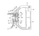
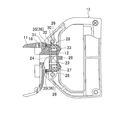
そして、ハウジング2の後端には、後方へスピンドル4と同軸の連結軸12を突設した後カバー11が、ハウジングの一部として一体にネジ止めされて、連結軸12にハンドル13が装着されている。ハンドル13は、図2,3にも示すように、左右一対の半割型14,14を組み付けてなる側面視D字状で、前端には、連結軸12に外装される筒状部15が、後端には上下方向のグリップ部16が夫々形成されている。すなわち、各半割型14,14を前端で連結軸12を挟むように組み付けることで、ハンドル13はスピンドル4の軸線上で連結軸12を中心に回転可能に連結される。筒状部15の前端には、連結軸12の根元に形成されたリング状の凹溝17に係合する前フランジ18が形成されて、組み付け状態でのハンドル13の抜け止めを図っている。この前フランジ18には、同心円周上で等間隔をおいて複数のロック孔19,19・・が穿設されている。
Then, at the rear end of the housing 2, a rear cover 11 having a connecting shaft 12 coaxial with the spindle 4 protruding rearward is integrally screwed as a part of the housing, and a handle 13 is attached to the connecting shaft 12. ing. As shown in FIGS. 2 and 3, the handle 13 has a D-shape in a side view formed by assembling a pair of left and right halves 14 and 14, and a cylindrical portion 15 that is externally mounted on the connecting shaft 12 is formed at the front end. The upper and lower grip portions 16 are formed at the rear ends. That is, by assembling each of the half dies 14, 14 so that the connecting shaft 12 is sandwiched between the front ends, the handle 13 is connected to be rotatable about the connecting shaft 12 on the axis of the spindle 4. A front flange 18 that engages with a ring-shaped concave groove 17 formed at the base of the connecting shaft 12 is formed at the front end of the cylindrical portion 15 to prevent the handle 13 from coming off in the assembled state. The front flange 18 is formed with a plurality of lock holes 19, 19,... At equal intervals on a concentric circle.
また、連結軸12とハンドル13との間には、ハンドル13の回転を任意に規制操作可能な規制手段20が設けられている。この規制手段20は、筒状部15内で連結軸12に外装されるロックリング21と、連結軸12に外装されてロックリング21を後方へ付勢する付勢手段としてのコイルバネ22と、筒状部15内でロックリング21の後方にあって回転操作可能に設けられるカム部材としての操作ノブ23とからなる。
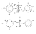
まずロックリング21は、図4(A)に示すように、連結軸12の後方部に設けた二面幅部に、中央に形成した二面幅の透孔24が嵌合することで、回転規制された状態で前後へスライド可能となっている。ロックリング21の前面外周には、前フランジ18のロック孔19と位相を合わせて前進位置で各ロック孔19に挿入可能な複数の爪25,25・・が突設される一方、後面外周には、同心円周上で等間隔をおいて3つの円弧状の突起26,26・・が突設されている。各突起26における周方向の前後面は、ロックリング21の後面に向かって下り傾斜となっている。 Further, between the connectingshaft 12 and the handle 13, a restricting means 20 capable of arbitrarily restricting the rotation of the handle 13 is provided. The restricting means 20 includes a lock ring 21 that is externally mounted on the connecting shaft 12 in the cylindrical portion 15, a coil spring 22 that is externally applied to the connecting shaft 12 and biases the lock ring 21 backward, An operation knob 23 as a cam member provided behind the lock ring 21 in the shape portion 15 so as to be rotatable.
First, as shown in FIG. 4A, thelock ring 21 is rotated by fitting a through hole 24 formed in the center with a two-sided width portion provided in the rear part of the connecting shaft 12. It can slide back and forth in a restricted state. On the outer periphery of the front surface of the lock ring 21, a plurality of claws 25, 25... That can be inserted into the respective lock holes 19 at the forward position in phase with the lock hole 19 of the front flange 18 are projected. Are provided with three arc- shaped projections 26, 26,... At equal intervals on a concentric circumference. The front and rear surfaces in the circumferential direction of each protrusion 26 are inclined downward toward the rear surface of the lock ring 21.
まずロックリング21は、図4(A)に示すように、連結軸12の後方部に設けた二面幅部に、中央に形成した二面幅の透孔24が嵌合することで、回転規制された状態で前後へスライド可能となっている。ロックリング21の前面外周には、前フランジ18のロック孔19と位相を合わせて前進位置で各ロック孔19に挿入可能な複数の爪25,25・・が突設される一方、後面外周には、同心円周上で等間隔をおいて3つの円弧状の突起26,26・・が突設されている。各突起26における周方向の前後面は、ロックリング21の後面に向かって下り傾斜となっている。 Further, between the connecting
First, as shown in FIG. 4A, the
次に、操作ノブ23は、図4(B)に示すように、筒状部15に嵌合する円盤状で、前面に連結軸12が当接し、後面外周に、筒状部15の後端に形成された後フランジ27が係合することで、連結軸12の後方で回転可能に保持されている。操作ノブ23の前面外周には、ロックリング21の突起26と同様に、同心円周上で等間隔をおいて3つの円弧状のカム突起28,28・・が突設されている。各カム突起28における周方向の前後面も、操作ノブ23の前面に向かって下り傾斜となっている。29は、操作ノブ23の後面中央に突設され、後フランジ27内で後方へ露出するツマミである。
Next, as shown in FIG. 4B, the operation knob 23 has a disk shape that fits into the cylindrical portion 15, the connection shaft 12 abuts on the front surface, and the rear end of the cylindrical portion 15 on the outer periphery of the rear surface. When the rear flange 27 formed in is engaged, it is rotatably held behind the connecting shaft 12. On the outer periphery of the front surface of the operation knob 23, three arc- shaped cam projections 28, 28,... Are projected at equal intervals on the concentric circumference, like the projection 26 of the lock ring 21. The front and rear surfaces in the circumferential direction of the cam protrusions 28 are also inclined downward toward the front surface of the operation knob 23. Reference numeral 29 denotes a knob that protrudes from the center of the rear surface of the operation knob 23 and is exposed rearward in the rear flange 27.
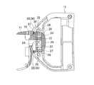
よって、ロックリング21は、コイルバネ22の付勢によって操作ノブ23に当接することになる。ここで、図5に示すように操作ノブ23が、各カム突起28が各突起26と前後方向で重なる位相(第1の回転位置)であると、ロックリング21はコイルバネ22の付勢に抗して前進位置にあって爪25を前フランジ18のロック孔19に挿入させる。よって、ハンドル13の回転がロックされることになる。逆に、図1のように操作ノブ23が、各カム突起28がロックリング21の突起26,26の間に位置する位相(第2の回転位置)であると、ロックリング21はコイルバネ22の付勢によって後退位置にあって爪25を前フランジ18のロック孔19から離間させるため、ハンドル13の回転はフリーとなる。
Therefore, the lock ring 21 comes into contact with the operation knob 23 by the bias of the coil spring 22. Here, as shown in FIG. 5, when the operation knob 23 is in a phase (first rotational position) where each cam projection 28 overlaps each projection 26 in the front-rear direction, the lock ring 21 resists the bias of the coil spring 22. Then, the claw 25 is inserted into the lock hole 19 of the front flange 18 in the forward position. Therefore, the rotation of the handle 13 is locked. On the contrary, as shown in FIG. 1, when the operation knob 23 is in a phase (second rotational position) in which each cam projection 28 is located between the projections 26, 26 of the lock ring 21, the lock ring 21 is connected to the coil spring 22. The handle 13 is free to rotate because the pawl 25 is separated from the lock hole 19 of the front flange 18 by being biased.
以上の如く構成された電動ドリル1においては、操作ノブ23の回転操作によってハンドル13の回転フリー状態と固定状態との選択が可能となる。すなわち、操作ノブ23を図1のように各カム突起28が突起26,26の間に位置する第2の回転位置に回転させると、前述のようにロックリング21は後退位置にあって前フランジ18に係合しない。よって、グリップ部16を把持してハンドル13を任意の角度に回転させて使用可能となる。
一方、ここから操作ノブ23を図5のように第1の回転位置に回転させると、各カム突起28が周方向へ移動してロックリング21の突起26に当接し、傾斜面同士の案内によって突起26が相対的にカム突起28に乗り上がることで、ロックリング21が前進位置へスライドする。よって、爪25が前フランジ18のロック孔19に挿入し、ハンドル13は当該角度で固定された状態で使用可能となる。 In the electric drill 1 configured as described above, it is possible to select the rotation free state and the fixed state of thehandle 13 by rotating the operation knob 23. That is, when the operation knob 23 is rotated to the second rotation position where each cam projection 28 is located between the projections 26 and 26 as shown in FIG. 1, the lock ring 21 is in the retracted position as described above, and the front flange is located. 18 is not engaged. Therefore, it is possible to use the handle 13 by gripping the grip portion 16 and rotating the handle 13 to an arbitrary angle.
On the other hand, when theoperation knob 23 is rotated to the first rotation position as shown in FIG. 5, the cam protrusions 28 move in the circumferential direction and come into contact with the protrusions 26 of the lock ring 21, and are guided by the inclined surfaces. As the projection 26 relatively rides on the cam projection 28, the lock ring 21 slides to the forward position. Therefore, the claw 25 is inserted into the lock hole 19 of the front flange 18 and the handle 13 can be used in a state of being fixed at the angle.
一方、ここから操作ノブ23を図5のように第1の回転位置に回転させると、各カム突起28が周方向へ移動してロックリング21の突起26に当接し、傾斜面同士の案内によって突起26が相対的にカム突起28に乗り上がることで、ロックリング21が前進位置へスライドする。よって、爪25が前フランジ18のロック孔19に挿入し、ハンドル13は当該角度で固定された状態で使用可能となる。 In the electric drill 1 configured as described above, it is possible to select the rotation free state and the fixed state of the
On the other hand, when the
このように、上記形態1の電動ドリル1によれば、ハウジング2の後端に、連結軸12を中心としてハンドル13を回転可能に連結すると共に、当該連結部分に、ハンドル13の回転を任意に規制操作可能な規制手段20を設けたことで、ハンドル13の回転フリー状態と固定状態とのどちらも任意に選択可能となる。よって、作業内容や姿勢の変更等に応じて、固定状態からハンドル13の向きを変えたり、逆に回転フリー状態から一時的に向きを固定したり等、ハンドル13がより柔軟な態様で使用可能となり、使い勝手に優れたものとなる。
As described above, according to the electric drill 1 of the first aspect, the handle 13 is rotatably connected to the rear end of the housing 2 around the connecting shaft 12, and the handle 13 is arbitrarily rotated to the connecting portion. By providing the restricting means 20 capable of restricting operation, either the rotation free state or the fixed state of the handle 13 can be arbitrarily selected. Therefore, the handle 13 can be used in a more flexible manner, such as changing the orientation of the handle 13 from the fixed state or conversely temporarily fixing the orientation from the rotation-free state according to changes in work content or posture, etc. And it will be easy to use.
特にここでは、ハンドル13の筒状部15に形成した前フランジ18を連結軸12に形成した凹溝17に係合させた状態で筒状部15を連結軸12に外装させることで、ハンドル13を回転可能に連結する一方、規制手段20を、筒状部15内で連結軸12へ回転不能に外装され、前フランジ18に係合する前進位置と前フランジ18から離れる後退位置との間をスライド可能なロックリング21と、そのロックリング21を後退位置へ付勢するコイルバネ22と、筒状部15内でロックリング21の後方にあって回転操作可能に設けられ、第1の回転位置でロックリング21をコイルバネ22の付勢に抗して前進位置へスライドさせてハンドル13の回転を規制し、第2の回転位置でロックリング21を後退位置へスライドさせてハンドル13の回転規制を解除する操作ノブ23とから形成したことで、規制手段20が省スペースで簡単に形成可能となっている。
In particular, here, the tubular portion 15 is externally attached to the connecting shaft 12 in a state where the front flange 18 formed on the tubular portion 15 of the handle 13 is engaged with the concave groove 17 formed on the connecting shaft 12. The restricting means 20 is externally mounted on the connecting shaft 12 in the cylindrical portion 15 so as to be non-rotatable, and is connected between a forward position engaged with the front flange 18 and a retracted position away from the front flange 18. A slidable lock ring 21, a coil spring 22 that urges the lock ring 21 to the retracted position, and provided behind the lock ring 21 in the cylindrical portion 15 so as to be rotatable. In the first rotational position, The lock ring 21 is slid to the forward position against the bias of the coil spring 22 to restrict the rotation of the handle 13, and the lock ring 21 is slid to the backward position at the second rotational position. 13 rotation restricting it formed from the operation knob 23 for releasing the regulation means 20 is in the easily formable in a space-saving.
[形態2]
次に、本発明の他の形態を説明する。但し、電動ドリルの構造は形態1と同様であるため、規制手段について主に説明する。また、規制手段においても同じ構成部には同一の符号を付して重複する説明は省略する。
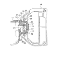
図6は、連結軸12を有する後カバー11とハンドル13とを示す説明図で、ここでの規制手段30は、筒状部15内で同様に二面幅同士の嵌合で連結軸12に回転不能状態で外装され、前進位置で前フランジ18に設けたロックプレート31に係合可能なロックリング32と、そのロックリング32を前方へ付勢するコイルバネ33と、操作ノブ23とから形成されている。 [Form 2]
Next, another embodiment of the present invention will be described. However, since the structure of the electric drill is the same as that of Form 1, the regulating means will be mainly described. Also, in the restricting means, the same components are denoted by the same reference numerals and redundant description is omitted.
FIG. 6 is an explanatory view showing therear cover 11 having the connecting shaft 12 and the handle 13, and the restricting means 30 here is similarly connected to the connecting shaft 12 by fitting two widths in the cylindrical portion 15. It is formed of a lock ring 32 that is externally mounted in a non-rotatable state and can be engaged with a lock plate 31 provided on the front flange 18 in the forward position, a coil spring 33 that biases the lock ring 32 forward, and an operation knob 23. ing.
次に、本発明の他の形態を説明する。但し、電動ドリルの構造は形態1と同様であるため、規制手段について主に説明する。また、規制手段においても同じ構成部には同一の符号を付して重複する説明は省略する。
図6は、連結軸12を有する後カバー11とハンドル13とを示す説明図で、ここでの規制手段30は、筒状部15内で同様に二面幅同士の嵌合で連結軸12に回転不能状態で外装され、前進位置で前フランジ18に設けたロックプレート31に係合可能なロックリング32と、そのロックリング32を前方へ付勢するコイルバネ33と、操作ノブ23とから形成されている。 [Form 2]
Next, another embodiment of the present invention will be described. However, since the structure of the electric drill is the same as that of Form 1, the regulating means will be mainly described. Also, in the restricting means, the same components are denoted by the same reference numerals and redundant description is omitted.
FIG. 6 is an explanatory view showing the
まずロックプレート31は、図7(A)に示すように、上下二箇所に夫々三角形の係止突起34,34を形成して、ハンドル13の組み付け状態で各半割型14に係止して回り止め状態で保持されるリング状の板体で、後面には、稜線が放射方向となる山形の回転歯35,35・・が同心円周上で連続状に突設されている。
また、ロックリング32は、図7(B)に示すように、前面には爪でなく、ロックプレート31の回転歯35と同様に、稜線が放射方向となる山形の固定歯36,36・・が、回転歯35と略同じ円周上且つ同じ数で連続状に突設されている。 First, as shown in FIG. 7 (A), thelock plate 31 is formed with triangular locking projections 34, 34 at two upper and lower positions, and locked to each half mold 14 in the assembled state of the handle 13. It is a ring-shaped plate body that is held in a non-rotating state, and on the rear surface thereof, chevron-shaped rotating teeth 35, 35,.
Further, as shown in FIG. 7B, thelock ring 32 is not a claw on the front surface, and is similar to the rotating teeth 35 of the lock plate 31 and has angle-shaped fixed teeth 36, 36,. However, it is projected in a continuous manner on the same circumference and the same number as the rotation teeth 35.
また、ロックリング32は、図7(B)に示すように、前面には爪でなく、ロックプレート31の回転歯35と同様に、稜線が放射方向となる山形の固定歯36,36・・が、回転歯35と略同じ円周上且つ同じ数で連続状に突設されている。 First, as shown in FIG. 7 (A), the
Further, as shown in FIG. 7B, the
よって、ロックリング32はコイルバネ33によって前方へ付勢されて、固定歯36を常にロックプレート31の回転歯35に噛合させている。この状態で操作ノブ23が、図9に示すように、各カム突起28がロックリング32の突起26と前後方向で重なる位相(第1の回転位置)にあると、ロックリング32は固定歯36を回転歯35に噛合させた状態で後退が規制される。一方、操作ノブ23が、各カム突起28が突起26,26の間に位置する位相(第2の回転位置)にあると、図8に示すように、ロックリング32は固定歯36が回転歯35から離れるまで後退可能となる。
Therefore, the lock ring 32 is urged forward by the coil spring 33, and the fixed teeth 36 are always meshed with the rotating teeth 35 of the lock plate 31. In this state, when the operation knob 23 is in a phase (first rotational position) where each cam projection 28 overlaps the projection 26 of the lock ring 32 in the front-rear direction as shown in FIG. Retraction is restricted in a state in which is engaged with the rotating tooth 35. On the other hand, when the operation knob 23 is in a phase (second rotational position) in which each cam projection 28 is located between the projections 26, 26, as shown in FIG. It can be retracted until it leaves 35.
以上の如く構成された電動ドリル1においては、操作ノブ23を各カム突起28が突起26,26の間に位置する図6の第2の回転位置に回転させると、前述のようにロックリング32はコイルバネ33の付勢によって固定歯36がロックプレート31の回転歯35に噛合する前進位置にある。しかし、ロックリング32の後退は規制されないため、ここからグリップ部16を把持してハンドル13を回転させると、図8のように固定歯36が相対的に回転歯35を乗り越えることでロックリング32をコイルバネ33の付勢に抗して後退させる。よって、ハンドル13を任意の角度へ回転させることができる。
一方、ここから操作ノブ23を図9の第1の回転位置に回転させると、各カム突起28が周方向へ移動してロックリング32の突起26と重なる同位相となり、ロックリング32の後退を規制する。よって、ハンドル13を回転させようとしても固定歯36が回転歯35を乗り越えることができないため、ハンドル13は当該角度で固定された状態となる。 In the electric drill 1 configured as described above, when theoperation knob 23 is rotated to the second rotation position in FIG. 6 where each cam projection 28 is located between the projections 26, 26, the lock ring 32 as described above. Is in a forward position where the fixed teeth 36 are engaged with the rotating teeth 35 of the lock plate 31 by the bias of the coil spring 33. However, since the backward movement of the lock ring 32 is not restricted, when the grip portion 16 is gripped from here and the handle 13 is rotated, the fixed tooth 36 gets over the rotation tooth 35 relatively as shown in FIG. Is retracted against the bias of the coil spring 33. Therefore, the handle 13 can be rotated to an arbitrary angle.
On the other hand, when theoperation knob 23 is rotated from here to the first rotational position in FIG. 9, each cam projection 28 moves in the circumferential direction and has the same phase as the projection 26 of the lock ring 32, and the lock ring 32 is retracted. regulate. Therefore, even if it is going to rotate handle 13, since fixed tooth 36 cannot get over rotating tooth 35, handle 13 will be in the state fixed at the angle concerned.
一方、ここから操作ノブ23を図9の第1の回転位置に回転させると、各カム突起28が周方向へ移動してロックリング32の突起26と重なる同位相となり、ロックリング32の後退を規制する。よって、ハンドル13を回転させようとしても固定歯36が回転歯35を乗り越えることができないため、ハンドル13は当該角度で固定された状態となる。 In the electric drill 1 configured as described above, when the
On the other hand, when the
このように、上記形態2の電動ドリル1においても、ハウジング2の後端に、連結軸12を中心としてハンドル13を回転可能に連結すると共に、当該連結部分に、ハンドル13の回転を任意に規制操作可能な規制手段30を設けたことで、ハンドル13の回転フリー状態と固定状態とのどちらも任意に選択可能となる。よって、作業内容や姿勢の変更等に応じて、固定状態からハンドル13の向きを変えたり、逆に回転フリー状態から一時的に向きを固定したり等、ハンドル13がより柔軟な態様で使用可能となる。よって、使い勝手に優れたものとなる。
Thus, also in the electric drill 1 of the said form 2, while connecting the handle | steering-wheel 13 centering | focusing on the connection shaft 12 with the rear end of the housing 2, rotation of the handle | steering-wheel 13 is arbitrarily controlled by the said connection part. By providing the control means 30 that can be operated, either the rotation free state or the fixed state of the handle 13 can be arbitrarily selected. Therefore, the handle 13 can be used in a more flexible manner, such as changing the orientation of the handle 13 from the fixed state or conversely temporarily fixing the orientation from the rotation-free state according to changes in work content or posture, etc. It becomes. Therefore, it is excellent in usability.
特に、規制手段30を、筒状部15内で連結軸12へ回転不能に外装され、前フランジ18に係合する前進位置と前フランジ18の回転を許容する後退位置との間をスライド可能なロックリング32と、そのロックリング32を前進位置へ付勢するコイルバネ33と、筒状部15内でロックリング32の後方にあって回転操作可能に設けられ、第1の回転位置でロックリング32を前進位置へ押圧してハンドル13の回転を規制し、第2の回転位置でロックリング32の押圧を解除し後退位置へのロックリング32のスライドを許容してハンドル13の回転規制を解除する操作ノブ23とから形成したことで、規制手段30が省スペースで簡単に形成可能となる。また、ここではロックプレート31の回転歯35とロックリング32の固定歯36との噛合によってハンドル13の回転角度が決定可能となるため、爪とロック孔との係合による形態1よりも細かい角度でハンドル13の向きを選択することができる利点がある。
In particular, the regulating means 30 is externally mounted on the connecting shaft 12 in the cylindrical portion 15 so as not to rotate, and is slidable between a forward position that engages with the front flange 18 and a backward position that allows rotation of the front flange 18. A lock ring 32, a coil spring 33 that urges the lock ring 32 to a forward position, and a rear portion of the lock ring 32 in the cylindrical portion 15 are provided so as to be rotatable. The lock ring 32 is provided at the first rotational position. To the forward position to restrict the rotation of the handle 13, release the pressure of the lock ring 32 at the second rotational position, allow the lock ring 32 to slide to the reverse position, and release the restriction of the rotation of the handle 13. By forming from the operation knob 23, the regulating means 30 can be easily formed in a space-saving manner. Here, since the rotation angle of the handle 13 can be determined by the engagement of the rotation teeth 35 of the lock plate 31 and the fixed teeth 36 of the lock ring 32, the angle is smaller than that in the first mode by the engagement between the claw and the lock hole. There is an advantage that the direction of the handle 13 can be selected.
なお、ロックリングやカム部材の形態は上記形態1,2に限らず、例えば形態1では爪やロック孔の数や形状を変更したり、形態2では回転歯と固定歯との数や形状を変更したりしても差し支えない。特に形態2では、ロックプレートをなくしてフランジに直接回転歯を形成することも可能である。
また、形態1,2でのカム部材は、突起とカム突起との連係によってロックリングをスライドさせるようにしているが、これも数の変更は勿論、何れか一方の突起をピンや半球形状に変更したり等、適宜設計変更可能である。付勢手段も、皿ばね等の他の弾性体を使用したりしてもよい。さらに、後カバーはハウジングと一体に形成しても差し支えない。
その他、電動工具もドリルに限らず、ハンマーやハンマードリル等の他のタイプであっても本発明は採用可能である。 In addition, the form of the lock ring and the cam member is not limited to the above-describedforms 1 and 2. For example, in form 1, the number and shape of the claws and lock holes are changed, and in form 2, the number and form of the rotating teeth and fixed teeth are changed. It can be changed. In particular, in Embodiment 2, it is possible to eliminate the lock plate and form the rotating teeth directly on the flange.
In the cam members in the first and second embodiments, the lock ring is slid by the linkage between the protrusion and the cam protrusion. Of course, the number of the protrusions can be changed, and either one of the protrusions can be formed into a pin or hemispherical shape. The design can be changed as appropriate. The biasing means may also use another elastic body such as a disc spring. Further, the rear cover may be formed integrally with the housing.
In addition, the power tool is not limited to a drill, and the present invention can be adopted even if it is another type such as a hammer or a hammer drill.
また、形態1,2でのカム部材は、突起とカム突起との連係によってロックリングをスライドさせるようにしているが、これも数の変更は勿論、何れか一方の突起をピンや半球形状に変更したり等、適宜設計変更可能である。付勢手段も、皿ばね等の他の弾性体を使用したりしてもよい。さらに、後カバーはハウジングと一体に形成しても差し支えない。
その他、電動工具もドリルに限らず、ハンマーやハンマードリル等の他のタイプであっても本発明は採用可能である。 In addition, the form of the lock ring and the cam member is not limited to the above-described
In the cam members in the first and second embodiments, the lock ring is slid by the linkage between the protrusion and the cam protrusion. Of course, the number of the protrusions can be changed, and either one of the protrusions can be formed into a pin or hemispherical shape. The design can be changed as appropriate. The biasing means may also use another elastic body such as a disc spring. Further, the rear cover may be formed integrally with the housing.
In addition, the power tool is not limited to a drill, and the present invention can be adopted even if it is another type such as a hammer or a hammer drill.
1・・電動ドリル、2・・ハウジング、3・・モータ、11・・後カバー、12・・連結軸、13・・ハンドル、14・・半割型、15・・筒状部、16・・グリップ部、17・・凹溝、18・・前フランジ、19・・ロック孔、20,30・・規制手段、21,32・・ロックリング、22,33・・コイルバネ、23・・操作ノブ、25・・爪、26・・突起、28・・カム突起、31・・ロックプレート、35・・回転歯、36・・固定歯。
1 .... Electric drill, 2 .... Housing, 3 .... Motor, 11 .... Rear cover, 12 .... Connecting shaft, 13 .... Handle, 14 .... Half type, 15 .... Cylinder, 16 .... Grip part, 17 ··· Groove, 18 · · Front flange, 19 · · Lock hole, 20, 30 · · Restricting means 21, 32 · · Lock ring, 22, 33 · · Coil spring, 23 · · Control knob, 25 ·· Claw, 26 ·· Projection, 28 · · Cam projection, 31 · · Lock plate, 35 · · Rotating tooth, 36 · · Fixed tooth
Claims (12)
- 電動工具であって、
ハウジングと、
前記ハウジングの後端に設けられ、前記ハウジングの前後方向の軸を中心として回転可能に連結されるハンドルと、
前記ハウジングとハンドルとの連結部分に設けられ、前記ハンドルの回転を任意に規制操作可能な規制手段と、を含む
ことを特徴とする電動工具。 An electric tool,
A housing;
A handle provided at a rear end of the housing and coupled to be rotatable about a longitudinal axis of the housing;
A power tool, comprising: a restricting means provided at a connecting portion between the housing and the handle and capable of arbitrarily restricting the rotation of the handle. - 前記ハウジングの後端に突設した連結軸と、
前記ハンドルの前端に設けられ、前記連結軸に外装可能な筒状部と、をさらに含み、
前記筒状部に形成したフランジを前記連結軸に形成した凹溝に係合させた状態で前記筒状部を前記連結軸に外装させることで、前記ハンドルを回転可能に連結する
ことを特徴とする請求項1に記載の電動工具。 A connecting shaft projecting from the rear end of the housing;
A cylindrical portion that is provided at a front end of the handle and can be externally mounted on the connecting shaft;
The handle is rotatably connected by mounting the cylindrical portion on the connecting shaft in a state where a flange formed on the cylindrical portion is engaged with a concave groove formed on the connecting shaft. The electric tool according to claim 1. - 前記規制手段を、
前記筒状部内で前記連結軸へ回転不能に外装され、前記フランジに係合する前進位置と前記フランジから離れる後退位置との間をスライド可能なロックリングと、
前記ロックリングを前記後退位置へ付勢する付勢手段と、
前記筒状部内で前記ロックリングの後方にあって回転操作可能に設けられ、第1の回転位置で前記ロックリングを前記付勢手段の付勢に抗して前記前進位置へスライドさせて前記ハンドルの回転を規制し、第2の回転位置で前記ロックリングを前記後退位置へスライドさせて前記ハンドルの回転規制を解除するカム部材と、から形成した
ことを特徴とする請求項2に記載の電動工具。 The regulating means,
A lock ring that is non-rotatably mounted on the connecting shaft in the cylindrical portion, and is slidable between a forward position engaged with the flange and a retracted position away from the flange;
Biasing means for biasing the lock ring to the retracted position;
The handle is provided behind the lock ring in the tubular portion so as to be rotatable, and the lock ring is slid to the advance position against the urging force of the urging means at the first rotation position. The electric motor according to claim 2, further comprising: a cam member that restricts the rotation of the steering wheel and releases the rotation restriction of the handle by sliding the lock ring to the retracted position at a second rotational position. tool. - 前記フランジに複数のロック孔を形成する一方、前記ロックリングの前面外周に、前記前進位置で前記ロック孔に挿入する複数の爪を形成し、前記ロックリングの後面外周に複数の突起を突設して、前記カム部材の前面外周に、前記第1の回転位置で前記突起と同じ位相となって前記ロックリングを前記前進位置へスライドさせ、前記第2の回転位置で前記突起と位相がずれて前記ロックリングを前記後退位置へスライドさせるカム突起を突設した
ことを特徴とする請求項3に記載の電動工具。 A plurality of lock holes are formed in the flange, and a plurality of claws are formed on the outer periphery of the front surface of the lock ring so as to be inserted into the lock hole at the forward movement position. Then, on the outer periphery of the front surface of the cam member, the lock ring is slid to the forward movement position with the same phase as the projection at the first rotation position, and the phase is shifted from the projection at the second rotation position. The power tool according to claim 3, further comprising a cam protrusion that slides the lock ring to the retracted position. - 前記付勢手段を、前記ロックリングの前方で前記連結軸に外装されるコイルバネとした
ことを特徴とする請求項3に記載の電動工具。 The power tool according to claim 3, wherein the biasing means is a coil spring that is sheathed on the connecting shaft in front of the lock ring. - 前記規制手段を、
前記筒状部内で前記連結軸へ回転不能に外装され、前記フランジに係合する前進位置と前記フランジの回転を許容する後退位置との間をスライド可能なロックリングと、
前記ロックリングを前記前進位置へ付勢する付勢手段と、
前記筒状部内で前記ロックリングの後方にあって回転操作可能に設けられ、第1の回転位置で前記ロックリングを前記前進位置へ押圧して前記ハンドルの回転を規制し、第2の回転位置で前記ロックリングの押圧を解除し前記後退位置への前記ロックリングのスライドを許容して前記ハンドルの回転規制を解除するカム部材と、から形成した
ことを特徴とする請求項2に記載の電動工具。 The regulating means,
A lock ring that is non-rotatably mounted on the connecting shaft in the cylindrical portion and is slidable between a forward position that engages with the flange and a reverse position that allows rotation of the flange;
Biasing means for biasing the lock ring to the forward position;
In the cylindrical part, it is provided behind the lock ring so as to be able to rotate, and the lock ring is pressed to the forward position at the first rotational position to restrict the rotation of the handle, and the second rotational position. The electric motor according to claim 2, further comprising: a cam member that releases the lock ring and allows the lock ring to slide to the retracted position and releases the rotation restriction of the handle. tool. - 前記フランジに、稜線が放射方向となる山形の回転歯を後面の同心円周上で連続状に形成したロックプレートを設ける一方、前記ロックリングの前面に、稜線が放射方向となる山形の固定歯を、前記回転歯と同じ円周上且つ同じ数で連続状に形成し、前記ロックリングの後面外周に複数の突起を突設して、前記カム部材の前面外周に、前記第1の回転位置で前記突起と同じ位相となって前記ロックリングを前記前進位置へスライドさせ、前記第2の回転位置で前記突起と位相がずれて前記ロックリングを前記後退位置へスライドさせるカム突起を突設した
ことを特徴とする請求項6に記載の電動工具。 The flange is provided with a lock plate in which chevron-shaped rotating teeth whose ridgeline is in the radial direction are continuously formed on the concentric circumference of the rear surface. A plurality of protrusions projecting on the outer periphery of the rear surface of the lock ring, and on the outer periphery of the front surface of the cam member at the first rotational position. The lock ring is slid to the forward position with the same phase as the protrusion, and a cam protrusion is provided to slide the lock ring to the retracted position out of phase with the protrusion at the second rotational position. The power tool according to claim 6. - 前記付勢手段を、前記ロックリングとカム部材との間で前記連結軸に外装されるコイルバネとした
ことを特徴とする請求項6に記載の電動工具。 The power tool according to claim 6, wherein the biasing means is a coil spring that is externally mounted on the connecting shaft between the lock ring and the cam member. - 前記突起及びカム突起における周方向の前後面を傾斜面とした
ことを特徴とする請求項4または7に記載の電動工具。 The electric tool according to claim 4 or 7, wherein the front and rear surfaces in the circumferential direction of the protrusion and the cam protrusion are inclined surfaces. - 前記カム部材を、後面中央に回転操作用のツマミを設けた操作ノブとした
ことを特徴とする請求項4または7に記載の電動工具。 The power tool according to claim 4 or 7, wherein the cam member is an operation knob provided with a knob for rotation operation at a center of a rear surface. - 前記ハンドルは、左右一対の半割型を組み付けてなる側面視D字状を有する
ことを特徴とする請求項2に記載の電動工具。 The electric power tool according to claim 2, wherein the handle has a D-shape in a side view formed by assembling a pair of left and right halves. - 前記ハウジングの中間部位に、下ハンドルを下向きに連結した
ことを特徴とする請求項1に記載の電動工具。 The power tool according to claim 1, wherein a lower handle is connected downward to an intermediate portion of the housing.
Applications Claiming Priority (2)
| Application Number | Priority Date | Filing Date | Title |
|---|---|---|---|
| JP2008283337A JP5319241B2 (en) | 2008-11-04 | 2008-11-04 | Electric tool |
| JP2008-283337 | 2008-11-04 |
Publications (1)
| Publication Number | Publication Date |
|---|---|
| WO2010052881A1 true WO2010052881A1 (en) | 2010-05-14 |
Family
ID=42152695
Family Applications (1)
| Application Number | Title | Priority Date | Filing Date |
|---|---|---|---|
| PCT/JP2009/005811 WO2010052881A1 (en) | 2008-11-04 | 2009-11-02 | Electric tool |
Country Status (2)
| Country | Link |
|---|---|
| JP (1) | JP5319241B2 (en) |
| WO (1) | WO2010052881A1 (en) |
Cited By (1)
| Publication number | Priority date | Publication date | Assignee | Title |
|---|---|---|---|---|
| US9308638B2 (en) | 2013-01-17 | 2016-04-12 | Seiko Epson Corporation | Power tool and auxiliary handle member |
Citations (8)
| Publication number | Priority date | Publication date | Assignee | Title |
|---|---|---|---|---|
| JPS61100381A (en) * | 1984-10-23 | 1986-05-19 | 松下電工株式会社 | Electric tool |
| JPH03117573A (en) * | 1989-09-08 | 1991-05-20 | Stihl Andreas | Working machine guide by hand |
| JPH0544477U (en) * | 1991-11-26 | 1993-06-15 | 日立工機株式会社 | Rotating handle |
| JPH05508353A (en) * | 1990-07-17 | 1993-11-25 | ローベルト ボツシユ ゲゼルシヤフト ミツト ベシユレンクテル ハフツング | Electric hand-held machine tools, especially angle grinders |
| JPH06143119A (en) * | 1992-11-06 | 1994-05-24 | Makita Corp | Portable rotary tool |
| JPH10313680A (en) * | 1997-05-16 | 1998-12-02 | Kioritz Corp | Handle device for motor-driven work machine |
| JP2003260677A (en) * | 2001-12-03 | 2003-09-16 | Milwaukee Electric Tool Corp | Handle arrangement for reciprocating saw |
| JP2006035419A (en) * | 2004-07-27 | 2006-02-09 | Hilti Ag | Hand tool device |
-
2008
- 2008-11-04 JP JP2008283337A patent/JP5319241B2/en not_active Expired - Fee Related
-
2009
- 2009-11-02 WO PCT/JP2009/005811 patent/WO2010052881A1/en active Application Filing
Patent Citations (8)
| Publication number | Priority date | Publication date | Assignee | Title |
|---|---|---|---|---|
| JPS61100381A (en) * | 1984-10-23 | 1986-05-19 | 松下電工株式会社 | Electric tool |
| JPH03117573A (en) * | 1989-09-08 | 1991-05-20 | Stihl Andreas | Working machine guide by hand |
| JPH05508353A (en) * | 1990-07-17 | 1993-11-25 | ローベルト ボツシユ ゲゼルシヤフト ミツト ベシユレンクテル ハフツング | Electric hand-held machine tools, especially angle grinders |
| JPH0544477U (en) * | 1991-11-26 | 1993-06-15 | 日立工機株式会社 | Rotating handle |
| JPH06143119A (en) * | 1992-11-06 | 1994-05-24 | Makita Corp | Portable rotary tool |
| JPH10313680A (en) * | 1997-05-16 | 1998-12-02 | Kioritz Corp | Handle device for motor-driven work machine |
| JP2003260677A (en) * | 2001-12-03 | 2003-09-16 | Milwaukee Electric Tool Corp | Handle arrangement for reciprocating saw |
| JP2006035419A (en) * | 2004-07-27 | 2006-02-09 | Hilti Ag | Hand tool device |
Cited By (1)
| Publication number | Priority date | Publication date | Assignee | Title |
|---|---|---|---|---|
| US9308638B2 (en) | 2013-01-17 | 2016-04-12 | Seiko Epson Corporation | Power tool and auxiliary handle member |
Also Published As
| Publication number | Publication date |
|---|---|
| JP2010110834A (en) | 2010-05-20 |
| JP5319241B2 (en) | 2013-10-16 |
Similar Documents
| Publication | Publication Date | Title |
|---|---|---|
| JP4227028B2 (en) | Screwdriver drill | |
| US7314097B2 (en) | Hammer drill with a mode changeover mechanism | |
| US6142242A (en) | Percussion driver drill, and a changeover mechanism for changing over a plurality of operating modes of an apparatus | |
| US6488451B1 (en) | Drive shaft lock | |
| EP2008746B1 (en) | Multi-speed drill and chuck assembly | |
| JP6746792B2 (en) | Torque transmission direction change mechanism | |
| US7124839B2 (en) | Impact driver having an external mechanism which operation mode can be selectively switched between impact and drill modes | |
| JP5628079B2 (en) | Vibration driver drill | |
| US8057134B2 (en) | Chuck assembly | |
| CA2549989C (en) | Screwdriver with ratchet mechanism | |
| KR20040068965A (en) | Side handles on drill/drivers | |
| JP5462241B2 (en) | Electric tool | |
| JP5340881B2 (en) | Impact tool | |
| JP5415176B2 (en) | switch | |
| US8931375B2 (en) | Ratchet device | |
| JP3955745B2 (en) | Angle drill | |
| JP4053865B2 (en) | Electric tool | |
| JP3655481B2 (en) | Vibration driver drill | |
| SE529928C2 (en) | Portable tool locking device | |
| JP4767593B2 (en) | Ignition switch operating device for vehicle | |
| US6450312B1 (en) | Easily direction-convertible ratchet assembly for a hand tool | |
| JP5319241B2 (en) | Electric tool | |
| JP2005118961A (en) | Driver drill | |
| JP2012006101A (en) | Impact tool | |
| JP2006116685A (en) | Portable tool |
Legal Events
| Date | Code | Title | Description |
|---|---|---|---|
| 121 | Ep: the epo has been informed by wipo that ep was designated in this application |
Ref document number: 09824582 Country of ref document: EP Kind code of ref document: A1 |
|
| NENP | Non-entry into the national phase |
Ref country code: DE |
|
| 122 | Ep: pct application non-entry in european phase |
Ref document number: 09824582 Country of ref document: EP Kind code of ref document: A1 |