JP5628079B2 - Vibration driver drill - Google Patents
Vibration driver drill Download PDFInfo
- Publication number
- JP5628079B2 JP5628079B2 JP2011083934A JP2011083934A JP5628079B2 JP 5628079 B2 JP5628079 B2 JP 5628079B2 JP 2011083934 A JP2011083934 A JP 2011083934A JP 2011083934 A JP2011083934 A JP 2011083934A JP 5628079 B2 JP5628079 B2 JP 5628079B2
- Authority
- JP
- Japan
- Prior art keywords
- cam
- spindle
- vibration
- pin
- slide
- Prior art date
- Legal status (The legal status is an assumption and is not a legal conclusion. Google has not performed a legal analysis and makes no representation as to the accuracy of the status listed.)
- Active
Links
Images


Classifications
-
- B—PERFORMING OPERATIONS; TRANSPORTING
- B25—HAND TOOLS; PORTABLE POWER-DRIVEN TOOLS; MANIPULATORS
- B25D—PERCUSSIVE TOOLS
- B25D16/00—Portable percussive machines with superimposed rotation, the rotational movement of the output shaft of a motor being modified to generate axial impacts on the tool bit
- B25D16/003—Clutches specially adapted therefor
-
- B—PERFORMING OPERATIONS; TRANSPORTING
- B25—HAND TOOLS; PORTABLE POWER-DRIVEN TOOLS; MANIPULATORS
- B25D—PERCUSSIVE TOOLS
- B25D11/00—Portable percussive tools with electromotor or other motor drive
- B25D11/06—Means for driving the impulse member
- B25D11/10—Means for driving the impulse member comprising a cam mechanism
- B25D11/102—Means for driving the impulse member comprising a cam mechanism the rotating axis of the cam member being coaxial with the axis of the tool
-
- B—PERFORMING OPERATIONS; TRANSPORTING
- B25—HAND TOOLS; PORTABLE POWER-DRIVEN TOOLS; MANIPULATORS
- B25D—PERCUSSIVE TOOLS
- B25D2250/00—General details of portable percussive tools; Components used in portable percussive tools
- B25D2250/165—Overload clutches, torque limiters
-
- B—PERFORMING OPERATIONS; TRANSPORTING
- B25—HAND TOOLS; PORTABLE POWER-DRIVEN TOOLS; MANIPULATORS
- B25D—PERCUSSIVE TOOLS
- B25D2250/00—General details of portable percussive tools; Components used in portable percussive tools
- B25D2250/245—Spatial arrangement of components of the tool relative to each other
Description
本発明は、スピンドルに軸方向の震動を付与する震動機構と、スピンドルの最大トルクを設定するクラッチ機構とを備えた震動ドライバドリルに関する。 The present invention relates to a vibration driver drill including a vibration mechanism that imparts axial vibration to a spindle and a clutch mechanism that sets a maximum torque of the spindle.
震動ドライバドリルは、ハウジングの前方へ突出させたスピンドルを回転させるドリルモードに加えて、スピンドルに軸方向の震動を付与する震動ドリルモードと、設定した最大トルクでスピンドルへのトルク伝達を遮断するクラッチモードとが選択可能となっている。このうち震動ドリルモードは、特許文献1に示すように、スピンドルに固着した第1カムと、その後方で回転可能且つ前後移動可能に設けられる第2カムと、第2カムに係合可能な震動切替レバーと、震動切替レバーを第2カムに対して係脱させるモードチェンジリングとを有する震動機構で構成される。すなわち、モードチェンジリングの回転操作によって震動切替レバーを第2カムに係止させて第2カムの回転を規制することで震動が得られるようになっている。また、クラッチモードは、モータの回転を減速する遊星歯車減速機構の最終段に設けられた回転可能なインターナルギヤと、そのインターナルギヤをボール等の係合部材を介して押圧するコイルバネと、コイルバネを受けるホルダをネジ送りすることでコイルバネの軸方向長さを変更可能なチェンジリングとを有するクラッチ機構で構成される。すなわち、チェンジリングの回転操作によって設定したコイルバネの付勢力を越えるトルクがスピンドルに加わると、インターナルギヤが空転してトルク伝達を遮断するものである。
In addition to the drill mode that rotates the spindle that protrudes to the front of the housing, the vibration driver drill has a vibration drill mode that applies axial vibration to the spindle and a clutch that blocks torque transmission to the spindle at the set maximum torque. The mode can be selected. Among them, the vibration drill mode is, as shown in
しかし、このような震動ドライバドリルにおいては、クラッチ機構のコイルバネを挟んで、径方向の内側に震動機構の切替部材(震動切替レバー)が、径方向の外側に操作部材(モードチェンジリング)がそれぞれ配置されるため、コイルバネとの干渉を避けるためにクラッチ機構と震動機構とを軸方向にずらせて配置する必要がある。よって、軸方向での工具全長が長くなり、コンパクト化の障害となる。 However, in such a vibration driver drill, with the coil spring of the clutch mechanism sandwiched, the vibration mechanism switching member (vibration switching lever) is radially inward, and the operation member (mode change ring) is radially outward. Therefore, it is necessary to displace the clutch mechanism and the vibration mechanism in the axial direction in order to avoid interference with the coil spring. Therefore, the total tool length in the axial direction becomes long, which is an obstacle to compactness.
そこで、本発明は、震動機構とクラッチ機構とを併設しても軸方向の長さを短くしてコンパクト化が達成できる震動ドライバドリルを提供することを目的としたものである。 Accordingly, an object of the present invention is to provide a vibration driver drill that can achieve downsizing by shortening the axial length even if a vibration mechanism and a clutch mechanism are provided.
上記目的を達成するために、請求項1に記載の発明は、クラッチ機構のコイルバネを、震動機構の切替部材と操作部材との間に配置して、切替部材と操作部材とを連結する連結部材を、係合部材の間を通してコイルバネを後端から迂回させて設けたことを特徴とするものである。
請求項2に記載の発明は、請求項1の構成において、カム機構を、スピンドルに固着される第1カムと、スピンドルに遊挿されて回転可能な第2カムと、筒状部内で回転規制され、第2カムに係止してその回転を規制する第1のスライド位置と第2カムから離間してその回転を許容する第2のスライド位置との間で前後方向へスライド可能なスライド部材とで形成し、スライド部材に、筒状部をその半径方向に遊挿するピン部材の一端を差し込み連結し、ピン部材の他端を切替部材に係合させて、切替部材の第1の位置でピン部材を介してスライド部材を第1のスライド位置に、第2の位置でピン部材を介してスライド部材を第2のスライド位置にそれぞれスライドさせることを特徴とするものである。
請求項3に記載の発明は、請求項2の構成において、スライド部材をリング状として複数のピン部材を差し込み連結し、筒状部に外装させたコイルバネにより、ピン部材を介してスライド部材を第1のスライド位置に付勢することを特徴とするものである。
In order to achieve the above object, according to the first aspect of the present invention, there is provided a connecting member that connects the switching member and the operating member by disposing the coil spring of the clutch mechanism between the switching member and the operating member of the vibration mechanism. Is provided with a coil spring detoured from the rear end through the engagement member.
According to a second aspect of the present invention, in the configuration of the first aspect, the cam mechanism includes a first cam that is fixed to the spindle, a second cam that is loosely inserted into the spindle and is rotatable, and a rotation restriction within the cylindrical portion. And a slide member that is slidable in the front-rear direction between a first slide position that is locked to the second cam and restricts its rotation and a second slide position that is spaced apart from the second cam and permits its rotation The first position of the switching member is formed by inserting and connecting one end of a pin member that loosely inserts the cylindrical portion in the radial direction to the slide member and engaging the other end of the pin member with the switching member. in the slide member via a pin member in a first slide position, it is characterized in that for each sliding the slide member via a pin member at a second location in the second slide position.
According to a third aspect of the present invention, in the configuration of the second aspect, the slide member is formed in a ring shape by inserting and connecting a plurality of pin members, and the coil member is externally attached to the cylindrical portion, and the slide member is inserted through the pin member. It is characterized by urging to one slide position.
請求項1に記載の発明によれば、震動機構の外側にクラッチ機構を干渉なく配置できる。よって、震動機構とクラッチ機構とを併設しても軸方向の長さを短くでき、コンパクト化が達成できる。
請求項2に記載の発明によれば、請求項1の効果に加えて、スライド部材の回転規制を筒状部の内部で行い、スライド部材と切替部材との連係を回転規制とかかわりなくピン部材で行うことができる。よって、筒状部にはピン部材が遊挿する必要最小限の長孔のみを形成すれば足り、筒状部の強度が確保できる。また、筒状部内への粉塵や水の浸入も生じにくくなる。
According to the first aspect of the present invention, the clutch mechanism can be disposed outside the vibration mechanism without interference. Therefore, even if the vibration mechanism and the clutch mechanism are provided, the axial length can be shortened, and compactness can be achieved.
According to the second aspect of the present invention, in addition to the effect of the first aspect, the rotation of the slide member is restricted inside the cylindrical portion, and the linkage between the slide member and the switching member is independent of the rotation restriction. Can be done. Therefore, it is sufficient to form only the minimum required long hole into which the pin member is loosely inserted in the cylindrical portion, and the strength of the cylindrical portion can be ensured. In addition, it is difficult for dust and water to enter the cylindrical portion.
以下、本発明の実施の形態を図面に基づいて説明する。
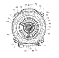
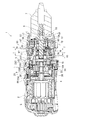
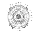
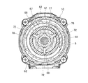
図1は、震動ドライバドリルの一例を示す縦断面図、図2はその分解斜視図で、震動ドライバドリル1は、本体ハウジング2内の後部(図1の右側を前方とする。)にモータ3を収容し、そのモータ3の前方に、前方へ突出するスピンドル6を備えたギヤアッセンブリ5を組み付けて、モータ3の出力軸4の回転をスピンドル6に伝達するもので、スピンドル6の前端には、先端でビットを把持可能なドリルチャック7が設けられている。
Hereinafter, embodiments of the present invention will be described with reference to the drawings.
FIG. 1 is a longitudinal sectional view showing an example of a vibration driver drill, FIG. 2 is an exploded perspective view thereof, and the
モータ3の前方には、出力軸4を軸支するモータブラケット8が組み付けられており、ギヤアッセンブリ5は、モータブラケット8に連結される筒状の第1ギヤケース9と、その第1ギヤケース9の前方に組み付けられ、大径部11と小径部12との二段筒形状を有する第2ギヤケース10とから形成されている。この第1、第2ギヤケース9,10は、第1ギヤケース9の前部外周面に突設された4つのボス13,13・・をネジ14,14・・によって第2ギヤケース10の後面に螺着することで、互いの結合がなされる。ギヤアッセンブリ5は、第2ギヤケース10の大径部11の後端外周面に突設された4つのボス15,15・・をネジ15a,15a・・(図5,6等に図示)で本体ハウジング2の前端に螺着することで、本体ハウジング2と結合されている。
A
ギヤアッセンブリ5の内部には、インターナルギヤ23A,23B,23C内で公転する複数の遊星ギヤ22,22・・を支持するキャリア21A,21B,21Cを、軸方向に三段配置してなる遊星歯車減速機構20が収容されて、モータ3の出力軸4が一段目の遊星ギヤ22に噛合している。
ここで、モータブラケット8の上下位置には、それぞれ左右方向に所定間隔をおいて前方へ突設され、左右同士で対向する透孔25を穿設した一対の結合板24,24が形成されている。一方、第1ギヤケース9の後端外周面の上下位置には、左右幅が結合板24,24の間隔に合致し、左右方向に貫通孔27を形成した突部26,26が接線方向に突設されている。モータブラケット8と第1ギヤケース9とは、図3にも示すように、上下の結合板24,24間に上下の突部26,26をそれぞれ嵌合させた状態で、出力軸4を中心とする点対称位置に配置される一対のピン28,28を左右方向から透孔25及び貫通孔27にそれぞれ貫通させることで互いに連結される。
Inside the
Here, at the upper and lower positions of the
また、モータブラケット8の前面に位置する一段目のインターナルギヤ23Aの上下には、ピン28の間隔に合わせた上下一対の面取部29,29と、その後方で面取部29と直交して半径方向に突出するフランジ部30,30とが形成されている。モータブラケット8と第1ギヤケース9との連結状態で上下のピン28,28は、フランジ部30,30の前方で面取部29,29に沿って第1ギヤケース9を貫通している。よって、インターナルギヤ23Aは、ピン28と面取部29との嵌合によって回転規制され、ピン28とフランジ部30とによって前後方向での位置決めがされることになる。31は、モータブラケット8とインターナルギヤ23Aとの間に介在されたワッシャーである。
In addition, a pair of upper and lower chamfered
さらに、遊星歯車減速機構20において、二段目のインターナルギヤ23Bは、回転可能且つ軸方向へ前後移動可能となっている。このインターナルギヤ23Bの外周面で前半部分には、周方向へ所定間隔をおいて複数の軸方向の外歯32,32・・が突設されて、後半部分は、周方向に結合溝33が形成されている。第1ギヤケース9内の前部には、内周面にインターナルギヤ23Bの外歯と同じ数の軸方向の内歯35,35・・を突設した結合リング34が保持されている。この結合リング34は、その外周に等間隔で突設した周方向の突条36,36・・を、第1ギヤケース9の前端内周面で軸方向に凹設した規制溝37,37・・に嵌合させることで回転規制されている。
Further, in the planetary gear
一方、インターナルギヤ23Bの外周面で後半部分には、速度切替リング38が外装されている。速度切替リング38は、外周面に設けた突起39,39・・と、第1ギヤケース9の後部内周面で軸方向に形成されたガイド溝40,40・・との嵌合によって前後移動のみ可能で、各突起39の外側から半径方向に挿着される結合ピン41の先端をインターナルギヤ23Bの結合溝33に挿入させている。上方に位置する突起39は、後方へ長く突出する延設部42を有しており、その延設部42の後端上面に突設された連結片43は、本体ハウジング2に前後へスライド可能に設けられた速度切替レバー44に、前後のコイルバネ45,45を介して連結されている。
On the other hand, a
よって、速度切替レバー44を後方へスライドさせると、連結片43を介して速度切替リング38が後退し、結合ピン41を介してインターナルギヤ23Bが、二段目の遊星ギヤ22との噛合を保ったまま一段目のキャリア21Aの外周に設けた噛み合い歯46にも噛合する。よって、二段目の減速がキャンセルされる高速モードとなる。逆に速度切替レバー44を前方へスライドさせると、速度切替リング38と共にインターナルギヤ23Bもキャリア21Aから離れて前進し、二段目の遊星ギヤ22との噛合を保ったまま、外歯32を結合リング34の内歯35に噛合させる。よって、二段目の減速が機能する低速モードとなる。
Therefore, when the
そして、ここでは第2ギヤケース10の小径部12の内側に、スピンドル6に軸方向への震動を付与する震動機構50が設けられ、小径部12の外側に、スピンドル6への所定の負荷でスピンドル6へのトルク伝達を遮断するクラッチ機構90が設けられて、後述する切替操作により、スピンドル6が回転しながら震動する震動ドリルモード、スピンドル6が回転のみ行うドリルモード、所定の負荷でスピンドル6へのトルク伝達を遮断するクラッチモード(ドライバモード)がそれぞれ選択可能となっている。以下、各機構について説明する。
Here, a
まず、震動機構50において、スピンドル6は、小径部12内で前後のボールベアリング16,17によって軸支されると共に、その後端が三段目のキャリア21Cと一体のロックカム51にスプライン結合されて、軸方向へ前後移動可能となっている。52は、小径部12内でロックカム51の前方から被着されるキャップである。
但し、スピンドル6は、その前方寄りに形成されたフランジ53とボールベアリング17との間で外装されたコイルバネ54によって、常態ではボールベアリング17の後方位置で外装された止め輪55がボールベアリング17に当接する前進位置に付勢されている。56は、小径部12の前端に嵌入されてボールベアリング17を位置決めするスペーサである。
First, in the
However, the
また、スピンドル6におけるボールベアリング16,17間には、前方からリング状の第1カム57、第2カム58が夫々同軸で外装されている。第1カム57は、その後面に、周方向に連続する第1カム歯59,59・・を放射状に形成し、スピンドル6に固着されている。第2カム58は、第1カム歯59と対向する前面に同じ形状の第2カム歯60,60・・を形成してスピンドル6に遊挿されて、前端外周にはフランジ61が周設されると共に、その後方には、図7にも示すように、周方向に等間隔をおいた3つの噛み合い突起62,62・・が突設されている。
さらに、第2カム58の前方で小径部12の内周面には、リング状の段部63が突設されており、第2カム58の後方には、図6にも示すように、小径部12内に固定されたストッパ板64の前面で複数のスチールボール65,65・・・・を介してワッシャー66が保持されている。よって、第2カム58は、段部63とワッシャー66との間で軸方向の移動を規制されることになる。
Further, between the
Further, a ring-shaped stepped
一方、小径部12内で第2カム58の外側には、スライド部材として、第2カム58の径と略同径のスライドリング67が収容されている。このスライドリング67には、図6,7にも示すように、周方向に等間隔をおいた3つの規制突起68,68・・が、半径方向でリングの内外へ突出するように一体形成されて、各規制突起68の外側への突出部分が、小径部12の内面に形成された軸方向の案内溝69にそれぞれ嵌合している。これによりスライドリング67は、回転規制された状態で小径部12内を前後移動可能となっている。各規制突起68には、半径方向に連結孔70がそれぞれ穿設されて、内側への突出部分は、中心側へ行くほど周方向の厚みが小さくなるテーパ形状となっている。このスライドリング67と第1、第2カム57,58とでカム機構を形成している。
On the other hand, a
また、小径部12において規制突起68が嵌合する各案内溝69には、前後に伸びる長孔71がそれぞれ穿設されて、各長孔71を小径部12の半径方向に貫通するピン部材としての連係ピン72の内端部が、規制突起68の連結孔70に挿入されている。小径部12の外周で長孔71から突出する連係ピン72の後方には、ワッシャー73が外装されると共に、その後方で小径部12の根元には、コイルバネ74が外装されている。よって、連係ピン72にはワッシャー73を介してコイルバネ74の付勢力が加わるため、連係ピン72及びこれと連結されるスライドリング67は前方へ付勢されることになる。
Further, each
但し、連係ピン72の外側で小径部12には、切替部材として、止め輪75によって前方への移動を規制された筒状の震動切替カム76が回転可能に外装されて、震動切替カム76の前端内周に周設したカム突条77に、連係ピン72の外端部が当接して前方への移動を規制している。このカム突条77の後端縁で周方向に等間隔をおいた3箇所には、図9にも示すように、台形状の係合凹部78,78・・が形成されている。
However, a cylindrical
よって、震動切替カム76を、係合凹部78と連係ピン72とが同じ位相となる第1の回転位置に回転させると、連係ピン72が係合凹部78に係合する前進位置となる。一方、震動切替カム76を、係合凹部78が連係ピン72からずれる位相となる第2の回転位置に回転させると、連係ピン72が係合凹部78から離脱してカム突条77の後端縁に乗り上がって係止する後退位置となる。連係ピン72の前進位置では、スライドリング67も前進して第2カム58のフランジ61に当接し、第2カム58の噛み合い突起62の間に規制突起68を位置させて第2カム58の回転を規制する(第1のスライド位置)。一方、連係ピン72の後退位置では、スライドリング67も後退して噛み合い突起62の間から規制突起68を退避させて第2カム58の回転をフリーとする(第2のスライド位置)。
Therefore, when the
この震動切替カム76の回転は、第2ギヤケース10の大径部11に回転可能に装着された操作部材としてのモード切替リング79によって行われる。このモード切替リング79は、前方に大径部11と略同径の操作部80を、後方に大径部11に内挿する小径の内挿部81をそれぞれ有する二段径で、内挿部81の外周には、周方向に等間隔をおいて3つの嵌合溝82,82・・が軸方向に形成されている。同じく嵌合溝82と同じ位相で震動切替カム76の後端には、3つの切欠き83,83・・が形成されている。
The
一方、第2ギヤケース10の大径部11と小径部12との間を繋ぐ閉塞部18の前面には、図5に示すように、周方向に所定長さを有する3つの収容凹部84,84・・が凹設されて、各収容凹部84に、両端を前方へ向けた連結部材としてのコ字状の連結棒85が、閉塞部18の半径方向に沿って配置されて、外側の端部86を内挿部81の嵌合溝82に嵌合させる一方、内側の端部87を震動切替カム76の切欠き83に係止させている。よって、操作部80を把持してモード切替リング79を回転させると、連結棒85を介して内側の震動切替カム76が同時に回転し、連係ピン72及びスライドリング67を前後動させることができる。
On the other hand, on the front surface of the closing
次に、クラッチ機構90について説明する。
まず、モード切替リング79の前方で小径部12には、内周に雌ネジ部92を形成したクラッチリング91が回転可能に外装されると共に、その内側に、外周に雄ネジ部94を形成したスプリングホルダ93が、クラッチリング91に螺合した状態で外装されている。このスプリングホルダ93は、内周に形成した突起95を小径部12の外周に形成した軸方向の溝96に嵌合させて、回転規制された状態で軸方向に前後移動可能となっている。また、スプリングホルダ93の後方で小径部12には、震動切替カム76よりも内径が大きいコイルバネ97が外装されて、コイルバネ97の前端がスプリングホルダ93に保持される一方、コイルバネ97の後端は、閉塞部18の前面に設けたワッシャー98に当接している。このワッシャー98は、連結棒85の内外の端部86,87間を通過する格好で閉塞部18の前面に当接して、モード切替リング79の回転に伴う連結棒85の移動と干渉しないようになっている。
Next, the
First, a
さらに、閉塞部18には、周方向に等間隔をおいて係合部材としての6本の係合ピン99,99・・が前後移動可能に貫通して、前端をワッシャー98に当接させる一方、後端を、三段目のインターナルギヤ23Cの前面に当接させている。インターナルギヤ23Cの前面には、係合ピン99の間に位置する台形状のカム突起100,100・・が周方向へ等間隔で当接されている。
よって、係合ピン99は、ワッシャー98を介して伝わるコイルバネ97の付勢力によってインターナルギヤ23Cの前面に押圧され、周方向でカム突起100と係合してインターナルギヤ23Cの回転規制を行う。クラッチリング91を回転操作すると、スプリングホルダ93が軸方向へネジ送りされてコイルバネ97を軸方向に伸縮させて押圧力を調整することになる。クラッチリング91の前側で小径部12には、止め輪101によってクリック板102が固定されて、そのクリック片103がクラッチリング91の前面に形成された複数の凹部104,104・・に係脱することで、クラッチリング91を回転操作する際のクリック作用が得られるようになっている。
Further, six engaging
Therefore, the
一方、第1ギヤケース9の規制溝37を除く前端内周面には、図4にも示すように、前端から軸方向の保持溝105,105・・が、周方向へ所定間隔をおいて形成されて、各保持溝105にラバーピン106が保持されている。このラバーピン106は、その内側に位置する結合リング34の外周面とインターナルギヤ23Cの外周面とに跨って当接して、第1ギヤケース9と結合リング34及びインターナルギヤ23Cとの間で圧縮されている。これによりインターナルギヤ23Cには、ラバーピン106によって回転方向への抵抗が常に加わることになる。
On the other hand, on the inner peripheral surface of the front end excluding the
さらに、閉塞部18において、収容凹部84の間には、図8にも示すように、前方から規制ピン107が遊挿されている。この規制ピン107は、前端に大径の頭部108を有して後端を閉塞部18の後方へ突出させて、インターナルギヤ23Cの外歯32に係合させるもので、閉塞部18と頭部108との間で規制ピン107に外装されたコイルバネ109によって前方へ付勢されている。規制ピン107の前方には、モード切替リング79の内挿部81が位置して頭部108が当接するようになっており、内挿部81の後端縁には、規制ピン107の位相に合わせた台形状の切欠き110,110・・が形成されている。すなわち、モード切替リング79の回転操作により、切欠き110を規制ピン107の位相に合わせると、頭部108が切欠き110に嵌合するまで規制ピン107が前進してインターナルギヤ23Cの外歯32から離間し、切欠き110と規制ピン107との位相をずらすと、規制ピン107が切欠き110から内挿部81の後端縁に乗り上がることで後退し、外歯32と係合する。この係合によりインターナルギヤ23Cの回転はロックされる。
Further, as shown in FIG. 8, the
以上の如く構成された震動ドライバドリル1においては、以下に説明するように、モード切替リング79の回転操作によって、3つの動作モードが選択可能となる。
まず、モード切替リング79の切欠き110が規制ピン107と同じ位相となる第1の切替位置(連結棒85は図5に二点鎖線で示す(A)の位置)では、前述のように規制ピン107は前進してインターナルギヤ23Cの回転ロックを解除する。このとき、モード切替リング79は連結棒85を介して震動切替カム76を、係合凹部78が連係ピン72からずれる第2の回転位置に回転させる。よって、第2カム60は回転フリー状態、インターナルギヤ23Cはコイルバネ97の押圧力で回転規制される状態となり、クラッチリング91の回転操作によって係合ピン99への押圧力(最大トルク)が変更可能なクラッチモードとなる。
In the
First, at the first switching position where the
このクラッチモードでモータ3を駆動させてスピンドル6を回転させると、ドリルチャック7に装着したドライバビットでネジ締め等を行うことができる。ここで、インターナルギヤ23Cには、ラバーピン106によって回転方向への抵抗が付与されているため、設定されるコイルバネ97の押圧力が小さい場合、モータ3の起動トルクが瞬間的に加わることがあっても、インターナルギヤ23Cの空転は抑制され、クラッチの早切れは生じない。
ネジ締めが進んでスピンドル6への負荷が、インターナルギヤ23Cを固定するコイルバネ97の押圧力を越えると、インターナルギヤ23Cのカム突起100が係合ピン99を前方へ押し出して相対的にカム突起100を乗り越えさせ、インターナルギヤ23Cを空転させてネジ締めを終了させる(クラッチ作動)。このときはラバーピン106による抵抗があってもインターナルギヤ23Cは空転する。なお、ドライバビットのネジへの押し付けによってスピンドル6が後退し、第1カム57が第2カム58と当接することがあっても、第2カム58は回転フリー状態であるため、第1カム57と共に回転する。よって、スピンドル6に震動は発生しない。
When the
When the screw tightening progresses and the load on the
次に、クラッチモードからモード切替リング79を前方から見て左回転させた第2の切替位置(連結棒85は図5に実線で示す(B)の位置)では、切欠き110は図8に示すように規制ピン107からずれる位相となるため、規制ピン107は内挿部81の後端縁に乗り上がって後退し、インターナルギヤ23Cの回転をロックする。一方、このときも震動切替カム76は、図9に示すように係合凹部78が連係ピン72からずれる第2の回転位置にあるため、第2カム58はフリー状態のままである。よって、コイルバネ97の押圧力の大小にかかわらずインターナルギヤ23Cの回転は常にロックされるドリルモードとなる。
このドリルモードでスピンドル6を回転させると、スピンドル6への負荷にかかわらずスピンドル6の回転は継続する。勿論スピンドル6に震動は発生しない。
Next, in the second switching position in which the
When the
そして、ドリルモードからモード切替リング79をさらに左回転させた第3の切替位置(連結棒85は図5に二点鎖線で示す(C)の位置及び図11の実線位置)では、図14に示すように切欠き110が規制ピン107からさらに離れるのみで位相がずれた状態は変わらないため、インターナルギヤ23Cの回転はロックされる。一方、震動切替カム76は、係合凹部78が連係ピン72と同じ位相となる第1の回転位置に達するため、図12及び図15に示すように、コイルバネ74の付勢によって連係ピン72が係合凹部78に係合して、図10及び図12,13に示すようにスライドリング67が前進し、第2カム58を回転規制する。よって、スピンドル6の後退位置で第1カム57と第2カム58とが当接する震動ドリルモードとなる。
Then, in the third switching position where the
この震動ドリルモードでドリルビット等を被加工材に押し当ててスピンドル6を後退させた状態で回転させると、スピンドル6と一体回転する第1カム57の第1カム歯59が、回転規制される第2カム58の第2カム歯60と干渉するため、スピンドル6に軸方向の震動が発生する。なお、インターナルギヤ23Cの回転はロックされているため、スピンドル6への負荷にかかわらずスピンドル6の回転は継続することになる。
In this vibration drill mode, when a drill bit or the like is pressed against a workpiece to rotate the
なお、第2ギヤケース10の大径部11の外周には、図2に示すように各動作モードの選択の目印111が表記されており、モード切替リング79には、各動作モードを示す3つのマーク112,112・・が表記されている。よって、目印111にマーク112を合わせることで所望の動作モードが得られる。
In addition, on the outer periphery of the large-
このように上記形態の震動ドライバドリル1によれば、クラッチ機構90のコイルバネ97を、震動機構50の震動切替カム76とモード切替リング79との間に配置して、震動切替カム76とモード切替リング79とを連結する連結棒85を、係合ピン99の間を通してコイルバネ97を後端から迂回させて設けたことで、震動機構50の外側にクラッチ機構90を干渉なく配置できる。よって、震動機構50とクラッチ機構90とを併設しても軸方向の長さを短くでき、コンパクト化が達成できる。
Thus, according to the
特にここでは、カム機構を、スピンドル6に固着される第1カム57と、スピンドル6に遊挿されて回転可能な第2カム58と、小径部12内で回転規制され、第2カム58に係止してその回転を規制する第1のスライド位置と第2カム58から離間してその回転を許容する第2のスライド位置との間で前後方向へスライド可能なスライドリング67とで形成し、スライドリング67に、小径部12をその半径方向に遊挿する連係ピン72の一端を差し込み連結し、連係ピン72の他端を震動切替カム76に係合させて、震動切替カム76の第1の回転位置で連係ピン72を介してスライドリング67を第1のスライド位置に、第2の回転位置で連係ピン72を介してスライドリング67を第2のスライド位置にそれぞれスライドさせるようにしている。すなわち、スライドリング67の回転規制を小径部12の内部(規制突起68と案内溝69)で行い、スライドリング67と震動切替カム76との連係を回転規制とかかわりなく連係ピン72で行うことができる。よって、小径部12には連係ピン72が遊挿する必要最小限の長孔71のみを形成すれば足り、小径部12の強度が確保できる。また、小径部12内への粉塵や水の浸入も生じにくくなる。
In particular, here, the cam mechanism includes a
なお、震動機構の連結部材は、上記形態の連結棒のように内側の切替部材(震動切替カム)と外側の操作部材(モード切替リング)と別体に設ける場合に限らず、組付けが可能であれば何れか一方と一体に設けてもよい。
また、切替部材の回転に伴うスライド部材のスライドも、例えばピン部材と切替部材との係合部分でコイルバネをなくして、切替部材に形成した傾斜溝若しくは傾斜孔にピン部材の外端を挿入し、切替部材の回転に伴う傾斜溝等の案内でピン部材を前後移動させたり、ピン部材を切替部材と結合して、スライド部材に形成した傾斜溝若しくは傾斜孔にピン部材の内端を挿入し、切替部材の回転によるピン部材の周方向の移動に伴い、傾斜溝等の案内でスライド部材を前後移動させたり等、適宜変更可能である。
In addition, the connection member of the vibration mechanism is not limited to the case where it is provided separately from the inner switching member (vibration switching cam) and the outer operation member (mode switching ring) like the connecting rod of the above form, but can be assembled. If so, it may be provided integrally with either one.
In addition, sliding of the slide member accompanying the rotation of the switching member also eliminates the coil spring at the engaging portion between the pin member and the switching member, for example, and inserts the outer end of the pin member into the inclined groove or inclined hole formed in the switching member. The pin member is moved back and forth by the guide of the inclined groove or the like accompanying the rotation of the switching member, or the pin member is coupled to the switching member and the inner end of the pin member is inserted into the inclined groove or inclined hole formed in the slide member. As the pin member moves in the circumferential direction due to the rotation of the switching member, the slide member can be moved back and forth with a guide such as an inclined groove or the like.
但し、カム機構も、上記形態では軸方向に移動規制されて回転可能な第2カムに、回転規制されて軸方向に移動可能なスライド部材を係脱させてカム機構の動作を切り替えるようにしているが、この構成に限らない。例えばスライド部材を省略して第2カムを回転規制して軸方向へ移動可能に設けて、ピン部材を第2カムに直接差し込み連結し、切替部材の回転操作により、ピン部材を介して第2カムを第1カムに対して接離動作させてカム機構の動作を切り替えるようにすることも可能である。この場合もピン部材と切替部材との係合やピン部材と第2カムとの係合に上記傾斜溝等を利用することができる。 However, the cam mechanism also switches the operation of the cam mechanism by engaging and disengaging the slide member that is rotationally restricted and movable in the axial direction with the second cam that is rotationally restricted in the axial direction in the above embodiment. However, it is not limited to this configuration. For example, the slide member is omitted, the second cam is restricted to rotate, and is provided so as to be movable in the axial direction. The pin member is directly inserted and connected to the second cam, and the second operation is performed via the pin member by rotating the switching member. It is also possible to switch the operation of the cam mechanism by moving the cam toward and away from the first cam. Also in this case, the above-described inclined groove or the like can be used for the engagement between the pin member and the switching member and the engagement between the pin member and the second cam.
一方、クラッチ機構においても、係合ピンの数の増減は勿論、係合ピンに代えて軸方向に並べた複数のボールを採用したりして差し支えない。
その他、遊星歯車減速機構における速度切替構造は省略してもよいし、モータブラケットと第1ギヤケースとの連結構造も上記形態に限定されない。
On the other hand, in the clutch mechanism, the number of engaging pins may be increased or decreased, and a plurality of balls arranged in the axial direction may be employed instead of the engaging pins.
In addition, the speed switching structure in the planetary gear reduction mechanism may be omitted, and the connection structure between the motor bracket and the first gear case is not limited to the above form.
1・・震動ドライバドリル、2・・本体ハウジング、3・・モータ、4・・出力軸、5・・ギヤアッセンブリ、6・・スピンドル、7・・ドリルチャック、8・・モータブラケット、9・・第1ギヤケース、10・・第2ギヤケース、11・・大径部、12・・小径部、20・・遊星歯車減速機構、23A〜23C・・インターナルギヤ、24・・結合板、26・・突部、28・・ピン、29・・面取部、30・・フランジ部、34・・結合リング、50・・震動機構、57・・第1カム、58・・第2カム、67・・スライドリング、71・・長孔、72・・連係ピン、74・・コイルバネ、76・・震動切替カム、78・・係合凹部、79・・モード切替リング、80・・操作部、85・・連結棒、90・・クラッチ機構、91・・クラッチリング、97・・コイルバネ、99・・係合ピン、105・・保持溝、106・・ラバーピン。
1 ....
Claims (3)
前記遊星歯車減速機構の最終段のインターナルギヤを回転可能に設けて、前記ギヤケースに、前記インターナルギヤの端面と係合可能な複数の係合部材を保持させ、その係合部材の前方に、前記係合部材を前記インターナルギヤの端面に押圧するコイルバネを設けて、前記コイルバネの押圧力を越える負荷の発生により、前記インターナルギヤを空転させて前記スピンドルへのトルク伝達を遮断可能なクラッチ機構を具備する一方、
前記筒状部内に、前記スピンドルに軸方向への震動を付与可能なカム機構を、前記筒状部の外側に、前記カム機構と連係して前記カム機構を動作させる第1の位置と、前記カム機構と連係せず前記カム機構を動作させない第2の位置とに移動可能な切替部材をそれぞれ設け、前記筒状部の半径方向で前記切替部材の外側に、連結部材を介して前記切替部材と連結され、前記切替部材を前記第1、第2の位置へ選択的に移動操作可能な操作部材を設けて、前記操作部材によって前記切替部材を前記第1の位置に移動させることで、前記カム機構により前記スピンドルに軸方向の震動を付与可能な震動機構を具備した震動ドライバドリルであって、
前記クラッチ機構の前記コイルバネを、前記震動機構の前記切替部材と前記操作部材との間に配置して、前記連結部材を、前記係合部材の間を通して前記コイルバネを後端から迂回させて設けたことを特徴とする震動ドライバドリル。 Provided in the housing is a motor, a planetary gear speed reduction mechanism housed in a gear case, and a spindle that is pivotally supported in a cylindrical portion projecting forward from the gear case and projecting forward from the housing. Enabling transmission to the spindle via the planetary gear reduction mechanism;
The final gear of the planetary gear speed reduction mechanism is rotatably provided, and the gear case holds a plurality of engagement members that can be engaged with the end face of the internal gear, and the front of the engagement member. A coil spring that presses the engagement member against the end face of the internal gear is provided, and when the load exceeding the pressing force of the coil spring is generated, the internal gear is idled so that torque transmission to the spindle can be cut off. While having a clutch mechanism,
A cam mechanism capable of imparting an axial vibration to the spindle in the cylindrical portion; a first position for operating the cam mechanism in conjunction with the cam mechanism on the outside of the cylindrical portion; A switching member that is movable to a second position that is not linked to a cam mechanism and that does not operate the cam mechanism is provided, and the switching member is disposed outside the switching member in the radial direction of the cylindrical portion via a connecting member. coupled with the switching member to the first, provided selectively move operable operating member to the second position, by moving the switch member to said first position by said operating member, said A vibration driver drill having a vibration mechanism capable of applying axial vibration to the spindle by a cam mechanism,
The coil spring of the clutch mechanism is disposed between the switching member and the operation member of the vibration mechanism, and the coupling member is provided between the engagement members so as to bypass the coil spring from the rear end. A vibration driver drill characterized by that.
前記スライド部材に、前記筒状部をその半径方向に遊挿するピン部材の一端を差し込み連結し、前記ピン部材の他端を前記切替部材に係合させて、前記切替部材の前記第1の位置で前記ピン部材を介して前記スライド部材を前記第1のスライド位置に、前記第2の位置で前記ピン部材を介して前記スライド部材を前記第2のスライド位置にそれぞれスライドさせることを特徴とする請求項1に記載の震動ドライバドリル。 The cam mechanism includes a first cam that is fixed to the spindle, a second cam that is loosely inserted into the spindle and is rotatable, and is restricted in rotation within the cylindrical portion, and is locked to the second cam. A slide member that is slidable in the front-rear direction between a first slide position that restricts rotation and a second slide position that is spaced apart from the second cam and permits rotation;
One end of a pin member that loosely inserts the cylindrical portion in the radial direction is inserted and connected to the slide member, and the other end of the pin member is engaged with the switching member, so that the first of the switching member is The slide member is slid to the first slide position via the pin member at a position , and the slide member is slid to the second slide position via the pin member at the second position. The vibration driver drill according to claim 1.
Priority Applications (5)
| Application Number | Priority Date | Filing Date | Title |
|---|---|---|---|
| JP2011083934A JP5628079B2 (en) | 2011-04-05 | 2011-04-05 | Vibration driver drill |
| US13/409,784 US8939228B2 (en) | 2011-04-05 | 2012-03-01 | Percussion driver drill |
| EP12157717.5A EP2508303B1 (en) | 2011-04-05 | 2012-03-01 | Percussion driver drill |
| CN201210091799.0A CN102729221B (en) | 2011-04-05 | 2012-03-30 | Percussion driver drill |
| RU2012113210/02A RU2591924C2 (en) | 2011-04-05 | 2012-04-04 | Impact drill-screwdriver |
Applications Claiming Priority (1)
| Application Number | Priority Date | Filing Date | Title |
|---|---|---|---|
| JP2011083934A JP5628079B2 (en) | 2011-04-05 | 2011-04-05 | Vibration driver drill |
Publications (3)
| Publication Number | Publication Date |
|---|---|
| JP2012218087A JP2012218087A (en) | 2012-11-12 |
| JP2012218087A5 JP2012218087A5 (en) | 2014-01-09 |
| JP5628079B2 true JP5628079B2 (en) | 2014-11-19 |
Family
ID=45808215
Family Applications (1)
| Application Number | Title | Priority Date | Filing Date |
|---|---|---|---|
| JP2011083934A Active JP5628079B2 (en) | 2011-04-05 | 2011-04-05 | Vibration driver drill |
Country Status (5)
| Country | Link |
|---|---|
| US (1) | US8939228B2 (en) |
| EP (1) | EP2508303B1 (en) |
| JP (1) | JP5628079B2 (en) |
| CN (1) | CN102729221B (en) |
| RU (1) | RU2591924C2 (en) |
Families Citing this family (14)
| Publication number | Priority date | Publication date | Assignee | Title |
|---|---|---|---|---|
| CN104117710B (en) * | 2013-04-23 | 2017-06-16 | 苏州宝时得电动工具有限公司 | Drill kind tool |
| US11260517B2 (en) | 2015-06-05 | 2022-03-01 | Ingersoll-Rand Industrial U.S., Inc. | Power tool housings |
| US10615670B2 (en) | 2015-06-05 | 2020-04-07 | Ingersoll-Rand Industrial U.S., Inc. | Power tool user interfaces |
| WO2016196984A1 (en) | 2015-06-05 | 2016-12-08 | Ingersoll-Rand Company | Power tools with user-selectable operational modes |
| WO2016196891A1 (en) * | 2015-06-05 | 2016-12-08 | Ingersoll-Rand Company | Power tool user interfaces |
| US10668614B2 (en) | 2015-06-05 | 2020-06-02 | Ingersoll-Rand Industrial U.S., Inc. | Impact tools with ring gear alignment features |
| CN105437131A (en) * | 2016-01-19 | 2016-03-30 | 郭艳明 | Vibration wrench |
| JP7154111B2 (en) * | 2018-11-08 | 2022-10-17 | 株式会社マキタ | Electric tool |
| US11267118B2 (en) * | 2018-11-08 | 2022-03-08 | Makita Corporation | Electric power tool |
| US11453109B2 (en) * | 2019-01-09 | 2022-09-27 | Makita Corporation | Power tool |
| JP7253397B2 (en) * | 2019-01-28 | 2023-04-06 | 株式会社マキタ | Electric tool |
| JP7458167B2 (en) * | 2019-11-08 | 2024-03-29 | 株式会社マキタ | electric screwdriver drill |
| RU203649U1 (en) * | 2020-05-21 | 2021-04-14 | Федеральное государственное бюджетное образовательное учреждение высшего образования "Саратовский государственный технический университет имени Гагарина Ю.А." | ULTRASONIC DRILL BIT FOR DRILLING POLYMER COMPOSITE MATERIALS |
| EP4059665A1 (en) * | 2020-12-21 | 2022-09-21 | Techtronic Cordless GP | Power tool with gear assembly |
Family Cites Families (26)
| Publication number | Priority date | Publication date | Assignee | Title |
|---|---|---|---|---|
| SU1743722A1 (en) * | 1988-05-17 | 1992-06-30 | Ю.К.Жебелев, Д.А.Юнусов, Л.А.Якубовска и А.Ф.Якунин | Impact-rotary type tool |
| DE19625850B4 (en) * | 1995-06-27 | 2008-01-31 | Matsushita Electric Works, Ltd., Kadoma | planetary gear |
| US5531278A (en) * | 1995-07-07 | 1996-07-02 | Lin; Pi-Chu | Power drill with drill bit unit capable of providing intermittent axial impact |
| US5897454A (en) * | 1996-01-31 | 1999-04-27 | Black & Decker Inc. | Automatic variable transmission for power tool |
| JP3291609B2 (en) * | 1996-02-13 | 2002-06-10 | 株式会社マキタ | Power tool clutch mechanism |
| SE9600934D0 (en) * | 1996-03-11 | 1996-03-11 | Atlas Copco Tools Ab | Power nutrunner with torque release xclutch |
| US6142242A (en) * | 1999-02-15 | 2000-11-07 | Makita Corporation | Percussion driver drill, and a changeover mechanism for changing over a plurality of operating modes of an apparatus |
| JP3655481B2 (en) * | 1999-02-15 | 2005-06-02 | 株式会社マキタ | Vibration driver drill |
| JP3911905B2 (en) * | 1999-04-30 | 2007-05-09 | 松下電工株式会社 | Impact rotary tool |
| US6676557B2 (en) * | 2001-01-23 | 2004-01-13 | Black & Decker Inc. | First stage clutch |
| US7101300B2 (en) * | 2001-01-23 | 2006-09-05 | Black & Decker Inc. | Multispeed power tool transmission |
| WO2004020156A1 (en) * | 2002-08-27 | 2004-03-11 | Matsushita Electric Works, Ltd. | Electrically operated vibrating drill/driver |
| US6796921B1 (en) * | 2003-05-30 | 2004-09-28 | One World Technologies Limited | Three speed rotary power tool |
| JP4227028B2 (en) | 2004-01-09 | 2009-02-18 | 株式会社マキタ | Screwdriver drill |
| DE102004051911A1 (en) * | 2004-10-26 | 2006-04-27 | Robert Bosch Gmbh | Hand tool, in particular drill |
| JP4501678B2 (en) * | 2004-12-22 | 2010-07-14 | パナソニック電工株式会社 | Vibration drill |
| US7410007B2 (en) * | 2005-09-13 | 2008-08-12 | Eastway Fair Company Limited | Impact rotary tool with drill mode |
| DE102005000199A1 (en) | 2005-12-21 | 2007-06-28 | Hilti Ag | Hand tool with ratchet impact mechanism |
| US7980324B2 (en) * | 2006-02-03 | 2011-07-19 | Black & Decker Inc. | Housing and gearbox for drill or driver |
| EP1857228B1 (en) * | 2006-05-19 | 2008-07-09 | Black & Decker, Inc. | Mode change mechanism for a power tool |
| US7513845B2 (en) * | 2006-08-01 | 2009-04-07 | Eastway Fair Company Limited | Variable speed transmission for a power tool |
| JP5030601B2 (en) * | 2007-01-22 | 2012-09-19 | 株式会社マキタ | Electric tool |
| EP2030709A3 (en) * | 2007-08-29 | 2013-01-16 | Positec Power Tools (Suzhou) Co., Ltd. | Power tool |
| US7798245B2 (en) * | 2007-11-21 | 2010-09-21 | Black & Decker Inc. | Multi-mode drill with an electronic switching arrangement |
| JP5275117B2 (en) * | 2008-10-10 | 2013-08-28 | 株式会社マキタ | Electric tool |
| JP5649500B2 (en) * | 2011-04-05 | 2015-01-07 | 株式会社マキタ | Electric tool |
-
2011
- 2011-04-05 JP JP2011083934A patent/JP5628079B2/en active Active
-
2012
- 2012-03-01 US US13/409,784 patent/US8939228B2/en active Active
- 2012-03-01 EP EP12157717.5A patent/EP2508303B1/en active Active
- 2012-03-30 CN CN201210091799.0A patent/CN102729221B/en active Active
- 2012-04-04 RU RU2012113210/02A patent/RU2591924C2/en active
Also Published As
| Publication number | Publication date |
|---|---|
| CN102729221B (en) | 2015-05-27 |
| EP2508303B1 (en) | 2016-02-24 |
| US8939228B2 (en) | 2015-01-27 |
| RU2591924C2 (en) | 2016-07-20 |
| CN102729221A (en) | 2012-10-17 |
| RU2012113210A (en) | 2013-10-10 |
| US20120255754A1 (en) | 2012-10-11 |
| EP2508303A1 (en) | 2012-10-10 |
| JP2012218087A (en) | 2012-11-12 |
Similar Documents
| Publication | Publication Date | Title |
|---|---|---|
| JP5628079B2 (en) | Vibration driver drill | |
| JP5649500B2 (en) | Electric tool | |
| JP4405900B2 (en) | Impact driver | |
| JP5030601B2 (en) | Electric tool | |
| JP4468786B2 (en) | Impact tools | |
| EP2554306B1 (en) | Electric power tool | |
| JP2004237422A (en) | Power tool | |
| JP2012218089A (en) | Power tool | |
| JP2016153153A (en) | Electric tool with vibration mechanism | |
| JP5284898B2 (en) | Impact tool | |
| JP4391921B2 (en) | Vibration drill | |
| JP4824812B2 (en) | Impact tools | |
| JP2011083868A (en) | Impact tool | |
| JP4053865B2 (en) | Electric tool | |
| JP5341429B2 (en) | Electric tool | |
| JP2001088052A (en) | Rotary tool with impact mechanism | |
| JP2012006101A (en) | Impact tool | |
| JP4063641B2 (en) | Electric tool | |
| JP2005118961A (en) | Driver drill | |
| CN107471164B (en) | Torque output tool | |
| JP4448049B2 (en) | Electric screwdriver | |
| JP2001088048A (en) | Rotational tool with hydraulic impact mechanism | |
| WO2010052881A1 (en) | Electric tool |
Legal Events
| Date | Code | Title | Description |
|---|---|---|---|
| A521 | Request for written amendment filed |
Free format text: JAPANESE INTERMEDIATE CODE: A523 Effective date: 20131118 |
|
| A621 | Written request for application examination |
Free format text: JAPANESE INTERMEDIATE CODE: A621 Effective date: 20131118 |
|
| A977 | Report on retrieval |
Free format text: JAPANESE INTERMEDIATE CODE: A971007 Effective date: 20140806 |
|
| TRDD | Decision of grant or rejection written | ||
| A01 | Written decision to grant a patent or to grant a registration (utility model) |
Free format text: JAPANESE INTERMEDIATE CODE: A01 Effective date: 20140902 |
|
| A61 | First payment of annual fees (during grant procedure) |
Free format text: JAPANESE INTERMEDIATE CODE: A61 Effective date: 20141001 |
|
| R150 | Certificate of patent or registration of utility model |
Ref document number: 5628079 Country of ref document: JP Free format text: JAPANESE INTERMEDIATE CODE: R150 |
|
| R250 | Receipt of annual fees |
Free format text: JAPANESE INTERMEDIATE CODE: R250 |
|
| R250 | Receipt of annual fees |
Free format text: JAPANESE INTERMEDIATE CODE: R250 |
|
| R250 | Receipt of annual fees |
Free format text: JAPANESE INTERMEDIATE CODE: R250 |
|
| R250 | Receipt of annual fees |
Free format text: JAPANESE INTERMEDIATE CODE: R250 |
|
| R250 | Receipt of annual fees |
Free format text: JAPANESE INTERMEDIATE CODE: R250 |
|
| R250 | Receipt of annual fees |
Free format text: JAPANESE INTERMEDIATE CODE: R250 |
|
| R250 | Receipt of annual fees |
Free format text: JAPANESE INTERMEDIATE CODE: R250 |