EP2554306B1 - Electric power tool - Google Patents
Electric power tool Download PDFInfo
- Publication number
- EP2554306B1 EP2554306B1 EP12175368.5A EP12175368A EP2554306B1 EP 2554306 B1 EP2554306 B1 EP 2554306B1 EP 12175368 A EP12175368 A EP 12175368A EP 2554306 B1 EP2554306 B1 EP 2554306B1
- Authority
- EP
- European Patent Office
- Prior art keywords
- switching member
- mode
- speed
- vibration
- link
- Prior art date
- Legal status (The legal status is an assumption and is not a legal conclusion. Google has not performed a legal analysis and makes no representation as to the accuracy of the status listed.)
- Active
Links
- 230000007246 mechanism Effects 0.000 claims description 60
- 230000033001 locomotion Effects 0.000 claims description 28
- 230000009467 reduction Effects 0.000 claims description 14
- 230000005540 biological transmission Effects 0.000 claims description 8
- 230000008859 change Effects 0.000 description 4
- 230000004048 modification Effects 0.000 description 3
- 238000012986 modification Methods 0.000 description 3
- 239000002184 metal Substances 0.000 description 2
- 230000009471 action Effects 0.000 description 1
- 230000004323 axial length Effects 0.000 description 1
- 230000000694 effects Effects 0.000 description 1
- 238000005096 rolling process Methods 0.000 description 1
Images


Classifications
-
- B—PERFORMING OPERATIONS; TRANSPORTING
- B60—VEHICLES IN GENERAL
- B60L—PROPULSION OF ELECTRICALLY-PROPELLED VEHICLES; SUPPLYING ELECTRIC POWER FOR AUXILIARY EQUIPMENT OF ELECTRICALLY-PROPELLED VEHICLES; ELECTRODYNAMIC BRAKE SYSTEMS FOR VEHICLES IN GENERAL; MAGNETIC SUSPENSION OR LEVITATION FOR VEHICLES; MONITORING OPERATING VARIABLES OF ELECTRICALLY-PROPELLED VEHICLES; ELECTRIC SAFETY DEVICES FOR ELECTRICALLY-PROPELLED VEHICLES
- B60L15/00—Methods, circuits, or devices for controlling the traction-motor speed of electrically-propelled vehicles
- B60L15/20—Methods, circuits, or devices for controlling the traction-motor speed of electrically-propelled vehicles for control of the vehicle or its driving motor to achieve a desired performance, e.g. speed, torque, programmed variation of speed
-
- B—PERFORMING OPERATIONS; TRANSPORTING
- B23—MACHINE TOOLS; METAL-WORKING NOT OTHERWISE PROVIDED FOR
- B23B—TURNING; BORING
- B23B45/00—Hand-held or like portable drilling machines, e.g. drill guns; Equipment therefor
- B23B45/008—Gear boxes, clutches, bearings, feeding mechanisms or like equipment
-
- B—PERFORMING OPERATIONS; TRANSPORTING
- B25—HAND TOOLS; PORTABLE POWER-DRIVEN TOOLS; MANIPULATORS
- B25B—TOOLS OR BENCH DEVICES NOT OTHERWISE PROVIDED FOR, FOR FASTENING, CONNECTING, DISENGAGING OR HOLDING
- B25B21/00—Portable power-driven screw or nut setting or loosening tools; Attachments for drilling apparatus serving the same purpose
- B25B21/02—Portable power-driven screw or nut setting or loosening tools; Attachments for drilling apparatus serving the same purpose with means for imparting impact to screwdriver blade or nut socket
-
- B—PERFORMING OPERATIONS; TRANSPORTING
- B25—HAND TOOLS; PORTABLE POWER-DRIVEN TOOLS; MANIPULATORS
- B25D—PERCUSSIVE TOOLS
- B25D11/00—Portable percussive tools with electromotor or other motor drive
- B25D11/06—Means for driving the impulse member
- B25D11/10—Means for driving the impulse member comprising a cam mechanism
- B25D11/102—Means for driving the impulse member comprising a cam mechanism the rotating axis of the cam member being coaxial with the axis of the tool
- B25D11/106—Means for driving the impulse member comprising a cam mechanism the rotating axis of the cam member being coaxial with the axis of the tool cam member and cam follower having the same shape
-
- B—PERFORMING OPERATIONS; TRANSPORTING
- B25—HAND TOOLS; PORTABLE POWER-DRIVEN TOOLS; MANIPULATORS
- B25D—PERCUSSIVE TOOLS
- B25D16/00—Portable percussive machines with superimposed rotation, the rotational movement of the output shaft of a motor being modified to generate axial impacts on the tool bit
- B25D16/006—Mode changers; Mechanisms connected thereto
-
- B—PERFORMING OPERATIONS; TRANSPORTING
- B25—HAND TOOLS; PORTABLE POWER-DRIVEN TOOLS; MANIPULATORS
- B25F—COMBINATION OR MULTI-PURPOSE TOOLS NOT OTHERWISE PROVIDED FOR; DETAILS OR COMPONENTS OF PORTABLE POWER-DRIVEN TOOLS NOT PARTICULARLY RELATED TO THE OPERATIONS PERFORMED AND NOT OTHERWISE PROVIDED FOR
- B25F5/00—Details or components of portable power-driven tools not particularly related to the operations performed and not otherwise provided for
- B25F5/001—Gearings, speed selectors, clutches or the like specially adapted for rotary tools
-
- B—PERFORMING OPERATIONS; TRANSPORTING
- B25—HAND TOOLS; PORTABLE POWER-DRIVEN TOOLS; MANIPULATORS
- B25D—PERCUSSIVE TOOLS
- B25D2216/00—Details of portable percussive machines with superimposed rotation, the rotational movement of the output shaft of a motor being modified to generate axial impacts on the tool bit
- B25D2216/0007—Details of percussion or rotation modes
- B25D2216/0023—Tools having a percussion-and-rotation mode
-
- B—PERFORMING OPERATIONS; TRANSPORTING
- B25—HAND TOOLS; PORTABLE POWER-DRIVEN TOOLS; MANIPULATORS
- B25D—PERCUSSIVE TOOLS
- B25D2216/00—Details of portable percussive machines with superimposed rotation, the rotational movement of the output shaft of a motor being modified to generate axial impacts on the tool bit
- B25D2216/0007—Details of percussion or rotation modes
- B25D2216/0038—Tools having a rotation-only mode
-
- B—PERFORMING OPERATIONS; TRANSPORTING
- B25—HAND TOOLS; PORTABLE POWER-DRIVEN TOOLS; MANIPULATORS
- B25D—PERCUSSIVE TOOLS
- B25D2216/00—Details of portable percussive machines with superimposed rotation, the rotational movement of the output shaft of a motor being modified to generate axial impacts on the tool bit
- B25D2216/0069—Locking means
-
- B—PERFORMING OPERATIONS; TRANSPORTING
- B25—HAND TOOLS; PORTABLE POWER-DRIVEN TOOLS; MANIPULATORS
- B25D—PERCUSSIVE TOOLS
- B25D2216/00—Details of portable percussive machines with superimposed rotation, the rotational movement of the output shaft of a motor being modified to generate axial impacts on the tool bit
- B25D2216/0084—Mode-changing mechanisms
- B25D2216/0092—Tool comprising two or more collaborating mode-changing mechanisms
-
- Y—GENERAL TAGGING OF NEW TECHNOLOGICAL DEVELOPMENTS; GENERAL TAGGING OF CROSS-SECTIONAL TECHNOLOGIES SPANNING OVER SEVERAL SECTIONS OF THE IPC; TECHNICAL SUBJECTS COVERED BY FORMER USPC CROSS-REFERENCE ART COLLECTIONS [XRACs] AND DIGESTS
- Y02—TECHNOLOGIES OR APPLICATIONS FOR MITIGATION OR ADAPTATION AGAINST CLIMATE CHANGE
- Y02T—CLIMATE CHANGE MITIGATION TECHNOLOGIES RELATED TO TRANSPORTATION
- Y02T10/00—Road transport of goods or passengers
- Y02T10/60—Other road transportation technologies with climate change mitigation effect
- Y02T10/72—Electric energy management in electromobility
Landscapes
- Engineering & Computer Science (AREA)
- Mechanical Engineering (AREA)
- Power Engineering (AREA)
- Transportation (AREA)
- Drilling And Boring (AREA)
- Portable Power Tools In General (AREA)
Description
- The present invention relates to an electric power tool including a plurality of operation mechanisms that cause a final output shaft protruded forward from a housing to operate in a predetermined operation mode such as a vibration drill mode or an impact mode so as to enable selection and use of a desired operation mode.
-
EP 2 210 712 A2claim 1 is based, discloses a changeover operation device for a power tool. - A conventional electric power tool includes a final output shaft such as a spindle or anvil that is protruded forward of a housing accommodating a motor and transmits rotation from the motor. The housing includes a plurality of operation mechanisms where the final output shaft is operated in a predetermined operation mode, such that a desired operation mechanism can be selected and used through manipulation of a mode switching member. For example, Japanese Patent No.
4227028 3655481 - In the electric power tools, torque is transmitted to a final output shaft from a motor through a planetary gear reduction mechanism arranged therebetween. In a transmission mechanism adopted herein, one internal gear of the planetary gear reduction mechanism is movable in the axial direction so as to enable switching between a high-speed mode and a low-speed mode. In the high-speed mode, the internal gear simultaneously meshes with a planet gear and a carrier thereof to cancel the speed reduction by the planet gear in this stage. On the other hand, in the low-speed mode, the internal gear meshes with only the planet gear to allow the speed reduction by the planet gear in this stage. The switching of speeds can be performed by manipulating a speed switching member provided to the housing.
- By providing the mode switching member and the speed switching member separately in this manner, it becomes possible to select the speed in the selected operation mode. However, in the predetermined operation mode such as the vibration drill mode or the impact mode, the high-speed mode is selected most of the time, and it is rare that the low-speed mode is actually used. Therefore, for example, when the operation mode is switched to the vibration drill mode with the mode switching member after the clutch mode or the drill mode is used at low speed, the speed switching member must be subsequently switched to the high-speed mode. This is cumbersome since operation is required for two members. There have been cases of a decrease in performance, particularly when it is forgotten to manipulate the speed switching member upon switching to the vibration drill mode and it is found that the low-speed mode is still held after work is started, the work must be temporarily stopped to appropriately manipulate the speed switching member.
- It is an object to provide an electric power tool that, even in a case where a mode switching member and a speed switching member are provided separately, requires no manipulation of the speed switching member in a predetermined operation mode that is only used in a high-speed mode, so that user-friendliness is achieved without causing a decrease in performance.
- In order to achieve the object described above, an electric power tool according to
claim 1 is provided. - A first aspect according to the invention is that a link unit is provided between the mode switching member and the speed switching member. With the link unit, a switching operation of a speed switching member to a high-speed side is performed in coordination with a selecting action of a mode switching member to a first predetermined operation mode so as to hold the rotation speed at high speed.
- A second preferable aspect provides a configuration according to the first aspect, in which the operation mode is selectable by a rotating operation of the mode switching member, and the speed switching member is provided in a rear of the mode switching member to be slidable in a front-rear direction between a forward position for high speed and a backward position for low speed.
- A third Preferable aspect provides a configuration according to the second aspect, in which the link unit includes a link member, a first protruding portion, and a second protruding portion. The link member is connected to the rear of the mode switching member to rotate integrally. The first protruding portion is provided along a rotational direction on an outer surface of the link member. In a switching position for the predetermined operation mode, the first protruding portion engages with a lower surface of the speed switching member in the forward position to restrict a backward movement of the speed switching member. The second protruding portion is connected with and inclined from the first protruding portion. Further, the second protruding portion engages with the lower surface of the speed switching member in the backward position along with a rotation of the link member to cause the speed switching member to move forward and engage with the first protruding portion.
- A fourth preferable aspect provides a configuration according to the first aspect, in which the operation mode is selectable by a rotating operation of the mode switching member. The speed switching member is provided in a rear of the mode switching member to be slidable in a front-rear direction between a backward position for high speed and a forward position for low speed.
- A fifth Preferable aspect provides a configuration according to the fourth aspect, in which the link unit is a link plate that is provided on a side of the mode switching member to protrude rearward. In a switching position for the predetermined operation mode, the link plate contacts the speed switching member in the backward position to restrict a forward movement of the speed switching member. An inclined guide portion is provided at a side edge of the link plate so as to contact the speed switching member in the forward position along with a rotation of the mode switching member to slide the speed switching member to the backward position.
- A sixth preferable aspect provides a configuration according to the first aspect, in which the plurality of operation mechanisms include a vibration mechanism that provides vibration in an axial direction to the final output shaft, and the predetermined operation mode is a vibration drill mode in which the vibration mechanism is activated.
- According to the first aspect, manipulation of the speed switching member becomes unnecessary in a predetermined operation mode used only in the high-speed mode, even in a case where the mode switching member and the speed switching member are provided separately. Thus, user-friendliness is achieved and a decrease in performance does not occur.
- According to the second to fifth aspects, the link unit can be formed easily.
- According to the sixth aspect, user-friendliness in the vibration drill mode used mostly in the high-speed mode can be improved, in addition to the effect of the first aspect.
-
-
FIG. 1 is a partial vertical-sectional view of an impact driver. -
FIG. 2 is a plan view of the impact driver. -
FIG. 3 is an exploded perspective view of an internal mechanism. -
FIG. 4 is an exploded perspective view of a housing and a vibration mechanism other than a body housing. -
FIG. 5 is a left side view of a unit portion. -
FIG. 6A is a sectional view along line A-A,FIG. 6B is a sectional view along line B-B, andFIG. 6C is a sectional view along line C-C. -
FIG. 7A is a left side view of the unit portion in an impact mode, andFIG. 7B is a bottom view thereof. -
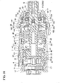
FIG. 8 is a vertical-sectional view of the unit portion in the impact mode. -
FIG. 9A is a left side view of the unit portion in a vibration drill mode, andFIG. 9B is a bottom view thereof. -
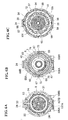
FIG. 10 is a vertical-sectional view of the unit portion in the vibration drill mode. -
FIG. 11A is a left side view of the unit portion in a drill mode, andFIG. 11B is a bottom view thereof. -
FIG. 12 is a vertical-sectional view of the unit portion in the drill mode. -
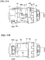
FIG. 13A is a left side view of the unit portion in a clutch mode, andFIG. 13B is a bottom view thereof. -
FIG. 14 is a vertical-sectional view of the unit portion in the clutch mode. -
FIGS. 15A and 15B are illustrative views of a vibration driver drill, respectively showing a plane of a unit portion in the vibration drill mode and a vertical section thereof. -
FIGS. 16A and 16B are illustrative views of the vibration driver drill, respectively showing a plane of the unit portion in the clutch mode and a vertical section thereof. - An embodiment will be described below based on the drawings.
-
FIGS. 1 and2 show animpact driver 1 as one example of an electric power tool, andFIGS. 3 and4 show a part of an internal mechanism thereof. Theimpact driver 1 has abody housing 2 formed by assembling left and righthalf housings 3. In thebody housing 2, amotor 4, a planetarygear reduction mechanism 6, and aspindle 7 are respectively accommodated in this order from the rear (with the right side inFIG. 1 being the front). In the front portion of thebody housing 2, a cylinder-shapedinner housing 8 accommodating astriking mechanism 9 that serves as an operation mechanism together with thespindle 7 is assembled. Ananvil 10 serving as a final output shaft, which is arranged coaxially with and in front of thespindle 7, is rotatably supported by theinner housing 8 and afront housing 12 fixed at the front end thereof so as to protrude forward. In thefront housing 12, avibration mechanism 90 serving as an operation mechanism is accommodated. The planetarygear reduction mechanism 6 and the mechanisms on the front side excluding thebody housing 2 form a unit.Reference numeral 13 denotes a ring-shaped bumper made of rubber that is fitted at the front end of thefront housing 12. Below thebody housing 2, ahandle 14 is provided to extend downward. In thehandle 14, aswitch 15 including atrigger 16 is accommodated. - The planetary
gear reduction mechanism 6 is accommodated in a cylinder-shapedgear housing 17 assembled in thebody housing 2. In the rear portion of thegear housing 17, apinion 18 fitted to anoutput shaft 5 of themotor 4 is rotatably supported and protrudes in thegear housing 17. The planetarygear reduction mechanism 6 includes afirst carrier 20 holding first-stage planet gears 21 that make planetary motion in a firstinternal gear 19 and asecond carrier 23 holding second-stage planet gears 24 that make planetary motion in a secondinternal gear 22, such that the first-stage planet gears 21 mesh with thepinion 18. Thesecond carrier 23 is formed integrally with the rear end of thespindle 7 and rotatably supported by aball bearing 25 in theinner housing 8. - Herein, the first
internal gear 19 includes a plurality ofinternal teeth 26 at predetermined intervals in the circumferential direction on the front inner circumference side. The secondinternal gear 22 includes a ring-shaped engaginggroove 27 on the front outer circumference side and a plurality ofouter teeth 28 provided to protrude at predetermined intervals in the circumferential direction on the rear outer circumference side. The secondinternal gear 22 is provided to be slidable between the forward position and the backward position. In the forward position, the secondinternal gear 22 meshes with both aspur gear 29 connected integrally with the rear of thesecond carrier 23 and the second-stage planet gear 24. In the backward position, theouter tooth 28 engages with theinternal tooth 26 of the firstinternal gear 19 so that the secondinternal gear 22 meshes only with the second-stage planet gear 24. - The
spur gear 29 is a separate gear located between thesecond carrier 23 and theplanet gear 24 and penetrated by asupport pin 30 that supports theplanet gear 24. The outer diameter of thesecond carrier 23 is smaller than the outer diameter of thespur gear 29 including the tooth tip.Reference numeral 36 denotes a holding ring that holds theball bearing 25 in thegear housing 17. - On the outside of the second
internal gear 22, aslide ring 31 that is slidable forward or backward along the inner circumferential surface of thegear housing 17 and theinner housing 8 is provided, and anengagement pin 32 that penetrates theslide ring 31 in the radial direction from the outside is engaged with the engaginggroove 27 of the secondinternal gear 22. On the outer circumference of the upper portion of theslide ring 31, aprotrusion 33 that protrudes through the upper portion of thegear housing 17 is provided. As shown inFIGS. 5 and6A , theprotrusion 33 is held by aslide button 34 via coil springs 35 on the front and rear sides of theprotrusion 33. Theslide button 34 serves as a speed switching member that is provided to thebody housing 2 so as to be slidable forward or backward, - As described above, a transmission mechanism is capable of switching the position of the second
internal gear 22 forward or backward via theslide ring 31 by a slide operation of theslide button 34 to the front or the rear. That is, a high-speed mode (second speed) in which the secondinternal gear 22 rotates integrally with thespur gear 29 to cancel the planetary motion of theplanet gear 24 is achieved in the forward position of the secondinternal gear 22 shown inFIGS. 1 ,2 , and8 . On the other hand, a low-speed mode (first speed) in which the secondinternal gear 22 is fixed to make the planetary motion of theplanet gear 24 is achieved in the backward position of the secondinternal gear 22 shown inFIG. 12 . - The
striking mechanism 9 has a structure by which a hammer is engaged with or disengaged from a pair ofarms 11 provided at the rear end of theanvil 10. The hammer herein is divided into a cylinder-shapedmain hammer 40 and asub hammer 42 having a bottomed cylinder shape that opens to the front. Themain hammer 40 is fitted to the exterior of the front end of thespindle 7 and provided with a pair ofpawls 41 that protrude at the front surface to engage with thearms 11. Thespindle 7 is loosely inserted to thesub hammer 42 so as to be coaxial therewith at the rear of themain hammer 40. Acircumference wall 43 of thesub hammer 42 is fitted to the exterior of themain hammer 40 from the rear. The diameter formed of the diameter of themain hammer 40 and the thickness of thecircumference wall 43 of thesub hammer 42 is equal to the outer diameter of a conventional hammer. - The
main hammer 40 is connected to thespindle 7 viaballs 46 that are fitted between reversed V-shapedgrooves 44 and V-shapedgrooves 45. The reversed V-shapedgrooves 44 are provided to extend from the front end toward the rear on the inner circumferential surface of themain hammer 40 and are tapered at the rear end. The V-shapedgrooves 45 are provided on the outer circumferential surface of thespindle 7 such that the front end thereof faces the front. - Between the
main hammer 40 and thesub hammer 42, acoil spring 47 is fitted to the exterior of thespindle 7, so that themain hammer 40 is biased to the forward position in which thepawl 41 engages with thearm 11 and thesub hammer 42 is biased rearward. Between thesub hammer 42 and thesecond carrier 23, awasher 48 is fitted to the exterior of thespindle 7. At aring groove 49 provided on the rear surface of thesub hammer 42, a plurality ofballs 50 that protrude from the rear surface are accommodated to form a thrust bearing. Thesub hammer 42 biased rearward by thecoil spring 47 is pressed in a rotatable state to the rear position in which theball 50 contacts thewasher 48. - On the inner circumferential surface of the
circumference wall 43 of thesub hammer 42, a plurality ofguide grooves 51 extending from the front end in the axial direction to the rear are formed at equal intervals in the circumferential direction. On the outer circumference of themain hammer 40, a plurality ofoval grooves 52 that are each shorter than theguide groove 51 are formed at the same intervals as theguide grooves 51 in the circumferential direction. Column-shaped connectingpins 53 are fitted between theguide groove 51 and theoval groove 52. Themain hammer 40 and thesub hammer 42 are connected by the connectingpin 53 so as to move individually in the axial direction and integrally in the rotational direction. - Furthermore, on the outer circumferential surface of the
main hammer 40 at the rear end, a ring-shapedfitting groove 54 is provided in the circumferential direction. On thecircumference wall 43 of thesub hammer 42, a plurality ofcircular holes 55 that pass through thecircumference wall 43 in the radial direction are formed between theguide grooves 51 in the rear end position of theguide groove 51. Eachball 56 is fitted with thecircular hole 55. - A switching
ring 57 is fitted to the exterior of thecircumference wall 43 of thesub hammer 42. The switchingring 57 is stepped to have two diameters, that is, to have asmall diameter portion 58 at the rear side and alarge diameter portion 59 at the front side. Thesmall diameter portion 58 slidingly contacts the outer circumferential surface of thecircumference wall 43 and alarge diameter portion 59 is apart from the outer circumferential surface of thecircumference wall 43 in the radial direction. On the outer circumferential surface of thesmall diameter portion 58, a ring-shapedgroove 60 is formed. The switchingring 57 is slidable forward or backward only between a frontside step portion 61 provided on the inner circumference of theinner housing 8 and a rearside step portion 62 provided on the outer circumference at the rear end of thecircumference wall 43. - As shown in
FIGS. 4 and5 , alink sleeve 63 serving as a link member is fitted to the exterior of theinner housing 8. To the front end outer circumference of thelink sleeve 63, amode switching ring 64 serving as a mode switching member located at the front of thebody housing 2 is fitted so as to be integrally rotatable. In point-symmetrical positions on the outer circumference of thelink sleeve 63, a pair of throughholes 65 that are oval and long in the front-rear direction are formed. On the outer circumferential surface along each throughhole 65, a quadrangle-shapedguide recess portion 66 slightly larger than the throughhole 65 is formed. - A cylinder-shaped
guide holder 67 is formed at a square-shapedflange portion 68 of which an outer side end portion fits with theguide recess portion 66. The cylinder-shapedguide holder 67 penetrates the throughhole 65 to protrude to the shaft center side of thelink sleeve 63 in the radial direction and is made movable in the front-rear direction by theflange portion 68 being guided by theguide recess portion 66. In theinner housing 8, aguide groove 69 is provided. Theguide groove 69 includes afront side groove 70, arear side groove 71 and aninclined groove 72. Thefront side groove 70 is formed in the circumferential direction in a position corresponding to the front end of the throughhole 65. Therear side groove 71 is formed in the circumferential direction in a position corresponding to the rear end of the throughhole 65. Theinclined groove 72 connects thefront side groove 70 and therear side groove 71, such that theguide holder 67 penetrates therethrough. As also shown inFIG. 6B , aguide pin 73 is inserted in theguide holder 67 from the shaft center side of theinner housing 8, and ahead portion 74 of theguide pin 73 is fitted with thegroove 60 of the switchingring 57. - In the
anvil 10, a small-diametertip end portion 76 provided to protrude at the front end of thespindle 7 is fitted in abearing hole 75 formed on the rear surface at the shaft center, so that theanvil 10 coaxially supports the front end of thespindle 7 in a rotatable manner. The bearinghole 75 accommodates aball 78 that is pressed by the end surface of thetip end portion 76 due to acoil spring 77 to receive load in the thrust direction. - Furthermore, at the front end of the
anvil 10 protruding from thefront housing 12, a mountinghole 79 for a bit is provided, and a chuck mechanism including asleeve 80 or the like that presses a ball 81 (seeFIG. 3 ) provided to theanvil 10 into the mountinghole 79 in the backward position is provided in order to mount and retain the bit inserted in the mountinghole 79. - The
vibration mechanism 90 is accommodated inside afront cylinder 37 joined coaxially with the front surface of theinner housing 8 and thefront housing 12 fitted to the exterior of thefront cylinder 37. In thefront housing 12, as also shown inFIG. 4 , afirst cam 91 formed with acam surface 91a at the rear surface is secured integrally to theanvil 10 and rotatably supported by aball bearing 92 in thefront housing 12. At the rear of thefirst cam 91, asecond cam 93 formed with acam surface 93a at the front surface is rotatably fitted to the exterior of theanvil 10. The rear surface of thesecond cam 93 is held by a plurality ofballs 94 accommodated along a ring-shaped receivingmetal 95 at the front surface of theinner housing 8, such that thecam surface 93a is engaged with thecam surface 91a of thefirst cam 91 in a normal state. On the outer circumference of thesecond cam 93, a plurality ofprotrusions 96 that protrude in the radial direction are formed at equal intervals in the circumferential direction. - In the
front cylinder 37, avibration switching ring 97 is provided. Thevibration switching ring 97 is a ring body having an inner diameter larger than the outer diameter of thesecond cam 93. As shown inFIG. 6C , a plurality ofouter protrusions 98 provided on the outer circumference are fitted inrestriction grooves 38 provided on the inner surface of thefront cylinder 37 and extending in the axial direction, so that thevibration switching ring 97 is held to be movable forward or backward in a state where rotation is restricted in thefront cylinder 37. On the inner circumference of thevibration switching ring 97, aninner protrusion 99 is provided to engage with theprotrusion 96 of thesecond cam 93 in a state where thevibration switching ring 97 is fitted to the exterior of thesecond cam 93. In other words, the rotation of thesecond cam 93 is restricted in the forward position in which thevibration switching ring 97 is fitted to the exterior of thesecond cam 93, and the rotation of thesecond cam 93 is allowed in the backward position in which thevibration switching ring 97 is apart from thesecond cam 93. It should be noted that acoil spring 100 is provided between thevibration switching ring 97 and theinner housing 8 in thefront cylinder 37, so that thevibration switching ring 97 is biased to the forward position. - A pair of
link plates 101 are latched to thevibration switching ring 97. Thelink plates 101 are band-shaped metal plates arranged point-symmetrically on the side surface at the front portion of theinner housing 8. Each of thelink plates 101 has arear plate portion 102, amiddle plate portion 103, and afront plate portion 104. Therear plate portion 102 fits in the corresponding one of a pair ofouter grooves 39 formed on the side surface of theinner housing 8 extending in the front-rear direction. Themiddle plate portion 103 goes a throughhole 37a provided in thefront cylinder 37 and bends inward from therear plate portion 102. Thefront plate portion 104 protrudes forward along the inner surface of thefront cylinder 37 from themiddle plate portion 103 such that the front end thereof bends inward. Thus, thelink plate 101 is movable in the front-rear direction due to therear plate portion 102 being guided by theouter groove 39. Therear plate portion 102 is fitted with theouter groove 39, and does not protrude from the outer circumferential surface of theinner housing 8.Reference numeral 105 denotes an engaging protrusion that is provided on the outer surface of therear plate portion 102 to protrude outward. Eachlink plate 101 is biased together with thevibration switching ring 97 to the forward position due to the front end of thefront plate portion 104 being latched to the front surface of thevibration switching ring 97 from the outside. - The
link sleeve 63 fitted to the exterior of theinner housing 8 is a cylinder-shaped body with a C-shaped cross section in which a part of thelink sleeve 63 in the circumferential direction is cut out along the whole length in the axial direction. Thelink sleeve 63 has acutout 82 extending along the circumferential direction at the middle portion. Aguide protrusion 83 provided to the outer circumferential surface of theinner housing 8 is fitted with thecutout 82, so that thelink sleeve 63 can rotate while a movement thereof in the front-rear direction is restricted. On the outer circumferential surface at the front side of thelink sleeve 63, a connectingprotrusion 84 that fits with a connectinggroove 85 provided extending in the front-rear direction on the inner circumferential surface at the rear side of themode switching ring 64 is provided. By the fitting of the connectinggroove 85 and the connectingprotrusion 84, themode switching ring 64 and thelink sleeve 63 are connected integrally in the rotational direction. - In the connected state, as shown in
FIG. 7A , the engagingprotrusion 105 of thelink plate 101 is located between the front end of thelink sleeve 63 and astep portion 86. Thestep portion 86 is provided along the circumferential direction on the inner circumferential surface of themode switching ring 64. A part of thestep portion 86 is arecess portion 87 provided to recess toward the front. Both sides of therecess portion 87 in the circumferential direction are inclined in a tapered manner. When the engagingprotrusion 105 is located in therecess portion 87, thevibration switching ring 97 biased to the front side by thecoil spring 100 is allowed to move to the forward position. On the other hand, when the engagingprotrusion 105 is located at thestep portion 86 other than therecess portion 87, thelink plate 101 moves backward and thevibration switching ring 97 moves to the backward position against the bias of thecoil spring 100. - On the outer circumferential surface at the rear side of the
link sleeve 63, as shown inFIGS. 4 and5 , a firstelongated protrusion 88A and a secondelongated protrusion 88B are provided. The firstelongated protrusion 88A serves as a first protruding portion along the circumferential direction. The secondelongated protrusion 88B serves as a second protruding portion inclined linearly from the end portion of the firstelongated protrusion 88A toward the rear along the circumferential direction. In a corner portion at the front end and on the left side (left side being a direction when seen from the front, hereinafter, "left" and "right" represent directions seen from the front) on the lower surface of theslide button 34, a receivingprotrusion 89 that engages with the tip end of the secondelongated protrusion 88B when thelink sleeve 63 rotates at the backward position for the first speed is provided. Thus, when thelink sleeve 63 rotates naturally, the receivingprotrusion 89 is guided forward along the secondelongated protrusion 88B, so that theslide button 34 moves forward. When the receivingprotrusion 89 moves up to the front of the firstelongated protrusion 88A, theslide button 34 reaches the forward position for the second speed. - On the lower surface of the
gear housing 17 at the rear of theinner housing 8, a pair ofmicroswitches plungers link sleeve 63, acontact member 108 is provided. Thecontact member 108 performs pushing or release of theplungers microswitches link sleeve 63. Themicroswitches handle 14 of theimpact driver 1. The controller monitors a torque value obtained from a torque sensor (not shown) provided to themotor 4 when the ON signal is input upon pushing of theplunger 107B of themicroswitch 106B and applies a brake to themotor 4 to block the torque transmitted to theanvil 10 when a set torque value is reached. - The rotation position (switching position) of the
mode switching ring 64 and thelink sleeve 63 and each operation mode regarding theimpact driver 1 configured as described above will be described. - First, in a first position in which the
mode switching ring 64 is rotated to the rightmost position when seen from the front as shown inFIGS. 7A and 7B , theguide holder 67 also moves in the right rotation direction and moves in theguide groove 69 to reach therear side groove 71. Theguide holder 67 is located at the rear end of the throughhole 65. Then, the switchingring 57 connected to theguide holder 67 via theguide pin 73 is in the backward position in which thelarge diameter portion 59 is located outside theball 56, as shown inFIG. 8 . In the backward position, theball 56 can move to a release position to sink in the inner circumferential surface of thecircumference wall 43 and be apart from thefitting groove 54 of themain hammer 40, thus achieving an impact mode that allows a backward movement of themain hammer 40. - At this time, the first
elongated protrusion 88A is located in the rear of the receivingprotrusion 89 of theslide button 34 to move theslide button 34 to the forward position. Therefore, a backward movement of theslide button 34 is restricted, and the high-speed mode is achieved constantly. The engagingprotrusion 105 of thelink plate 101 is displaced to the left side from therecess portion 87 and latched to thestep portion 86. Therefore, thelink plate 101 is in the backward position, causing thevibration switching ring 97 to move backward and allowing thesecond cam 93 to rotate. (It should be noted that inFIG. 7A and the subsequent side views of a unit portion, themode switching ring 64 is shown with a partial cutout for the sake of illustrating the position of the engagingprotrusion 105.) Thecontact member 108 is not in contact with either of theplungers microswitches - Therefore, when the
trigger 16 provided to thehandle 14 is manipulated to drive themotor 4, the rotation of theoutput shaft 5 is transmitted to thespindle 7 via the planetarygear reduction mechanism 6, rotating thespindle 7. Thespindle 7 causes themain hammer 40 to rotate via theball 46, and theanvil 10 is engaged with themain hammer 40 to rotate. Therefore, thread fastening or the like is possible with a bit fitted to the tip end of theanvil 10. At this time, thesub hammer 42 connected to themain hammer 40 in the rotational direction via the connectingpin 53 also rotates integrally with themain hammer 40. It should be noted that even if thefirst cam 91 is rotated along with the rotation of theanvil 10, thesecond cam 93 engaged with thefirst cam 91 is allowed to rotate. Therefore, thesecond cam 93 also rotates integrally, and vibration does not occur in theanvil 10. - When the torque of the
anvil 10 is increased by further thread fastening, a difference occurs between the rotation of themain hammer 40 and the rotation of thespindle 7. Therefore, theball 46 rolls along the V-shapedgroove 45, causing themain hammer 40 to move backward against the bias of thecoil spring 47 while rotating relatively with respect to thespindle 7. Thesub hammer 42 at this time rotates integrally with themain hammer 40 with the connectingpin 53 therebetween while allowing a backward movement of themain hammer 40. - Then, when the
pawl 41 of themain hammer 40 is disengaged from thearm 11, thecoil spring 47 is biased and theball 46 is rolled toward the tip end of the V-shapedgroove 45, and then themain hammer 40 is moved forward while rotating. Thus, thepawl 41 of themain hammer 40 engages with thearm 11 again to generate a rotational striking force (impact). By repeating the engagement with and disengagement from theanvil 10, the tightness is increased. - In the above state, the
sub hammer 42 also rotates together with themain hammer 40, and the engagement with and disengagement from theanvil 10 involves a sum of the mass of thehammers ball 50 on the rear surface rolling on the front surface of thewasher 48 at the time of rotation, thesub hammer 42 can rotate smoothly even if thecoil spring 47 is extended or compressed along with the front or back movement of themain hammer 40. Furthermore, even if themain hammer 40 repeats the front or back movement at the time of impact occurrence, thesub hammer 42 maintains the backward position and does not move forward or backward, thus preventing vibration at the time of impact occurrence. - Next, in a second position in which the
mode switching ring 64 is rotated to the left to a predetermined angle from the first position as shown inFIGS. 9A and 9B , theguide holder 67 also moves in the left rotation direction in the circumferential direction and moves in theguide groove 69 to reach thefront side groove 70. Theguide holder 67 is located at the front end of the throughhole 65. The switchingring 57 is in the forward position in which thesmall diameter portion 58 is located outside theball 56, as shown inFIG. 10 . In the forward position, theball 56 is pushed by thesmall diameter portion 58 as shown inFIG. 12 and fixed to a connecting position to fit with thefitting groove 54 of themain hammer 40. Therefore, themain hammer 40 and thesub hammer 42 are connected in the front-rear direction such that a backward movement of themain hammer 40 is restricted. - At this time, the engaging
protrusion 105 of thelink plate 101 moves forward and fits with therecess portion 87, because therecess portion 87 is in the same phase. Thus, thevibration switching ring 97 moves to the forward position, and a vibration drill mode that restricts the rotation of thesecond cam 93 is achieved. - It should be noted that when the
link plate 101 moves forward, thevibration switching ring 97 may not be able to move to the forward position due to a match in phase between theinner protrusion 99 of thevibration switching ring 97 and theprotrusion 96 of thesecond cam 93. However, when thefirst cam 91 rotates together with theanvil 10 to rotate thesecond cam 93 that engages with thefirst cam 91, a difference occurs in phase between theprotrusion 96 and theinner protrusion 99 because thevibration switching ring 97 is biased by thecoil spring 100. Therefore, thevibration switching ring 97 is able to move forward and restrict the rotation of thesecond cam 93. - The first
elongated protrusion 88A is still located in the rear of the receivingprotrusion 89 in the same manner as in the impact mode. Therefore, a backward movement of theslide button 34 is restricted, and the high-speed mode is achieved constantly. Thecontact member 108 presses only theplunger 107A of themicroswitch 106A, and therefore a clutch is not activated. - When the
trigger 16 is manipulated to rotate thespindle 7, thespindle 7 causes themain hammer 40 to rotate via theball 46, thereby engaging theanvil 10 with themain hammer 40 to rotate. When thefirst cam 91 rotates along with the rotation of the anvil, thecam surface 91a and thecam surface 93a of thesecond cam 93 of which the rotation is restricted interfere with each other. Theanvil 10 is rotatably supported in a state where there is a play in the front and the rear of thearm 11. Therefore, due to the interference between the cam surfaces 91a and 93a, vibration of theanvil 10 occurs in the axial direction. Thesub hammer 42 connected to themain hammer 40 in the rotational direction via the connectingpin 53 also rotates integrally with themain hammer 40. - An engagement or disengagement operation of the
main hammer 40 with respect to theanvil 10 is not performed even if the torque of theanvil 10 increases, because a backward movement of themain hammer 40 is restricted by theball 56. Thus, impact does not occur, and theanvil 10 rotates integrally with thespindle 7. - Next, in a third position in which the
mode switching ring 64 is rotated to the left to a predetermined angle from the second position as shown inFIGS. 11A and 11B , theguide holder 67 also moves in the left rotation direction in the circumferential direction but stays located in thefront side groove 70. Therefore, the state in which theguide holder 67 is located at the front end of the throughhole 65 does not change. Accordingly, as also shown inFIG. 12 , the switchingring 57 is in the forward position, and theball 56 is pushed by thesmall diameter portion 58 and fixed in the connecting position to fit with thefitting groove 54 of themain hammer 40. Thus, themain hammer 40 and thesub hammer 42 are connected in the front-rear direction, a drill mode in which a backward movement of themain hammer 40 is restricted is achieved. - In the above state, the engaging
protrusion 105 of thelink plate 101 is latched to thestep portion 86 again due to therecess portion 87 moving to the left side. Therefore, thelink plate 101 is in the backward position, causing thevibration switching ring 97 to move backward and allowing thesecond cam 93 to rotate freely. Thecontact member 108 simultaneously presses theplungers microswitches - The first
elongated protrusion 88A moves away from theslide button 34 to the left side and the end portion of the secondelongated protrusion 88B is located in the rear of the receivingprotrusion 89. Therefore, a backward movement of theslide button 34 becomes possible, as shown inFIG. 12 . Thus, either mode of high or low speed can be selected. - When the
trigger 16 is manipulated to rotate thespindle 7, thespindle 7 causes themain hammer 40 to rotate via theball 46, thereby causing theanvil 10 engaged with themain hammer 40 to rotate. At this time, thesub hammer 42 connected to themain hammer 40 in the rotational direction via the connectingpin 53 also rotates integrally with themain hammer 40. It should be noted that even if thefirst cam 91 rotates along with the rotation of theanvil 10, vibration does not occur in theanvil 10 because thesecond cam 93 opposing thefirst cam 91 is rotatable. - An engagement or disengagement operation of the
main hammer 40 with respect to theanvil 10 is not performed even if the torque of theanvil 10 increases, because a backward movement of themain hammer 40 is restricted by theball 56. Thus, impact does not occur, and theanvil 10 rotates integrally with thespindle 7. - Next, in a fourth position in which the
mode switching ring 64 is rotated to the left to a predetermined angle from the third position as shown inFIGS. 13A and 13B , theguide holder 67 also moves in the left rotation direction in the circumferential direction but stays located in thefront side groove 70. Therefore, the state in which theguide holder 67 is located at the front end of the throughhole 65 does not change, as shown inFIG. 14 . Thus, the switchingring 57 is in the forward position, such that theball 56 is pushed by thesmall diameter portion 58 and fixed in the connecting position to fit with thefitting groove 54 of themain hammer 40. Themain hammer 40 and thesub hammer 42 are connected in the front-rear direction to restrict a backward movement of themain hammer 40. - At this time, the engaging
protrusion 105 of thelink plate 101 is latched to thestep portion 86 in the same manner as in the third position. Therefore, thelink plate 101 is in the backward position and thevibration switching ring 97 is moved backward, to make thesecond cam 93 rotatable. It should be noted that thecontact member 108 presses only theplunger 107B of themicroswitch 106B, and therefore the clutch mode is achieved. - The first and second
elongated protrusions slide button 34. Therefore, a slide operation of theslide button 34 to either the front or the rear is possible. - Therefore, when the
trigger 16 is manipulated to rotate thespindle 7, thespindle 7 causes themain hammer 40 to rotate via theball 46, thereby causing theanvil 10 engaged with themain hammer 40 to rotate. At this time, thesub hammer 42 connected to themain hammer 40 in the rotational direction via the connectingpin 53 also rotates integrally with themain hammer 40. It should be noted that even if thefirst cam 91 rotates along with the rotation of theanvil 10, vibration does not occur in theanvil 10 because thesecond cam 93 opposing thefirst cam 91 is rotatable. - Then, when the torque of the
anvil 10 increases and the torque value detected by the torque sensor reaches the set torque value, brake is applied to themotor 4 such that the torque transmission from thespindle 7 to theanvil 10 is blocked. - It should be noted that, as shown in
FIG. 2 , indications M1 (impact mode), M2 (vibration drill mode), M3 (drill mode), and M4 (clutch mode) corresponding to respective operation modes are indicated on the outer circumferential surface of themode switching ring 64. Each operation mode is selected by aligning each indication to anarrow 109 indicated at the front end on the upper surface of thebody housing 2. - In the case of switching from the drill mode or the clutch mode used at low speed to the vibration drill mode or the impact mode, the operation is performed in reverse. More specifically, the second
elongated protrusion 88B apart from theslide button 34 engages with the receivingprotrusion 89 of theslide button 34 in the backward position due to the rightward rotation of thelink sleeve 63. The receivingprotrusion 89 is caused to slide relatively along the secondelongated protrusion 88B along with the rotation of thelink sleeve 63 and theslide button 34 is caused to move to the forward position. Thus, the high-speed mode is achieved constantly in the vibration drill mode and the impact mode. - In this manner, the
impact driver 1 in the embodiment described above inludes, between themode switching ring 64 and theslide button 34, a link unit (thelink sleeve 63 and the first and secondelongated protrusions slide button 34 to the high-speed side is performed in conjunction with a selecting operation of themode switching ring 64 to the impact mode or the vibration drill mode and the rotation speed is held at high speed. Therefore, manipulation of theslide button 34 becomes unnecessary in the predetermined operation mode (the impact mode or the vibration drill mode) used only in the high-speed mode, even in a case where themode switching ring 64 and theslide button 34 are provided separately. Thus, user-friendliness is achieved and a decrease in performance does not occur. - Particularly herein, the mode switching member is the
mode switching ring 64 that enables selection of an operation mode through a rotating operation, and the speed switching member is provided in the rear of themode switching ring 64 to be slidable in the front-rear direction between the forward position for high speed and the backward position for low speed. The link unit includes thelink sleeve 63, the firstelongated protrusion 88A, and the secondelongated protrusion 88B. Thelink sleeve 63 is connected in the rear of themode switching ring 64 and rotates integrally with themode switching ring 64. The firstelongated protrusion 88A is provided along the rotational direction on the outer surface of thelink sleeve 63 and, in the switching position for the impact mode and the vibration drill mode, engages with the receivingprotrusion 89 of theslide button 34 in the forward position to restrict a backward movement of theslide button 34. The secondelongated protrusion 88B is connected with and inclined from the firstelongated protrusion 88A and engages with the lower surface of theslide button 34 in the backward position along with the rotation of thelink sleeve 63 to cause theslide button 34 to move forward and engage with the firstelongated protrusion 88A. Thus, the link unit can be formed easily. - The plurality of operation mechanisms include the
vibration mechanism 90 that provides vibration in the axial direction to theanvil 10, and the high-speed mode is achieved automatically in the vibration drill mode. Therefore, user-friendliness in the vibration drill mode used mostly in the high-speed mode can be improved. - It should be noted that although the high-speed mode is achieved constantly in the vibration drill mode and the impact mode in the embodiment described above, the high-speed mode may be achieved constantly only in one of the operation modes or the high-speed mode may be achieved constantly in another operation mode.
- Although there is only one inclined second elongated protrusion, the second elongated protrusion can be connected with the first elongated protrusion on each of the left and right, in a case where the switching position for the vibration drill mode or the impact mode is located between switching positions for other operation modes.
- Furthermore, the first and second elongated protrusions are provided to the link sleeve separate from the mode switching ring and the first and second elongated protrusions are engaged with or disengaged from the receiving protrusion provided to the slide button to move the slide button in the embodiment described above. However, the first and second protruding portions are not limited to such elongated protrusions and may be appropriately modified to, for example, a quadrangle-shaped protrusion for the first protruding portion and a triangle-shaped protrusion for the second protruding portion such that a trapezoid shape is formed as a whole, or the like.
- Although the forward position of the slide button is for high speed and the backward position is for low speed in the transmission mechanism of the embodiment described above, the present teachings can be applied to a transmission mechanism with a reverse configuration. One such example is shown in
FIGS. 15A, 15B ,16A and 16B . It should be noted that identical components as in the previous embodiment are denoted by the same reference numerals, and redundant descriptions are omitted. - An electric power tool shown herein is a
vibration driver drill 120. Aninner housing 121 assembled in the front of a motor includes a planetarygear reduction mechanism 122, avibration mechanism 123 serving as an operation mechanism, and a mechanical clutch mechanism 124, forming a unit. Three operation modes of the vibration drill mode, the drill mode, and the clutch mode are selectable. The basic configuration is similar to the vibration driver drill described in Japanese Patent No.4227028 - The planetary
gear reduction mechanism 122 is provided with the secondinternal gear 22 that is movable forward or backward. A slide operation of theslide button 34 enables switching between the backward position inFIGS. 15A and 15B in which the secondinternal gear 22 simultaneously meshes with thefirst carrier 20 and the second-stage planet gear 24, and the forward position inFIGS. 16A and 16B in which the secondinternal gear 22 meshes only with theplanet gear 24 such that rotation is restricted in theinner housing 121. Thus, herein, the high-speed mode (second speed) is achieved in the backward position, and the low-speed mode (first speed) in the forward position. - The
vibration mechanism 123 includes thefirst cam 91, thesecond cam 93, a pair of vibration switching levers 125, and acoil spring 126. Thefirst cam 91 is integrally secured to thespindle 7 that serves as the final output shaft. Thesecond cam 93 is fitted to be rotatable to the exterior at the rear of thefirst cam 91. A pair of vibration switching levers 125 is movable forward or backward between the forward position in which the vibration switching levers 125 engage with thesecond cam 93 to restrict the rotation thereof, and the backward position in which the vibration switching levers 125 is apart from thesecond cam 93 to allow the rotation thereof. Acoil spring 126 biases eachvibration switching lever 125 to the forward position. By a rotating operation of themode switching ring 64, thevibration switching lever 125 can be pressed to the backward position against the bias of thecoil spring 126. - In the clutch mechanism 124, a
third carrier 127 is provided to thespindle 7, and a thirdinternal gear 129 with which a third-stage planet gear 128 supported by thethird carrier 127 meshes is provided to be rotatable. By pressing the thirdinternal gear 129 with acoil spring 132 via aball 130 and awasher 131 and changing the axial length of thecoil spring 132 through a rotating operation of achange ring 133 provided to the front end of theinner housing 121, the pressing force of thecoil spring 132 that restricts the rotation of the thirdinternal gear 129 is adjustable. It should be noted that the tip end of thespindle 7 is provided with achuck 134 for gripping a bit. - In a first position in which the
mode switching ring 64 is rotated to the leftmost position when seen from the front, a forward movement of thevibration switching lever 125 is allowed to restrict the rotation of thesecond cam 93. Further, the inner circumference of thewasher 131 that rotates integrally with theinner housing 121 is engaged with theinner housing 121 to restrict the movement of theball 130. Thus, the vibration drill mode that restricts the rotation of the thirdinternal gear 129 is achieved. In a second position in which themode switching ring 64 is rotated rightward to a predetermined angle from the first position, thevibration switching lever 125 is moved backward to allow thesecond cam 93 to rotate. Further, the inner circumference of thewasher 131 is released from engagement with theinner housing 121. Thus, the clutch mode in which the restriction on the rotation of the thirdinternal gear 129 is released is achieved. Furthermore, in a third position in which themode switching ring 64 is rotated rightward to a predetermined angle from the second position, the backward position of thevibration switching lever 125 is maintained. Further, the inner circumference of thewasher 131 is engaged again with theinner housing 121. Thus, the drill mode in which the rotation of the thirdinternal gear 129 is restricted is achieved. - Herein, a
link ring 135 that rotates integrally with themode switching ring 64 is connected to the rear end of themode switching ring 64, and afront link plate 136 protruding toward the rear and having aninclined guide portion 137 as the left side edge is formed at the rear end of thelink ring 135. At the front end of theslide button 34, arear link plate 138 is provided so as to protrude toward the front and having aninclined guide portion 139 as the right side edge with the same angle as theinclined guide portion 137. In the first position of the mode switching ring 64 (for the vibration drill mode), thefront link plate 136 is located in the front of therear link plate 138 to restrict a forward movement of theslide button 34 as shown inFIG. 15A . In the second and third positions (for the clutch mode and the drill mode), thefront link plate 136 moves to the right side of therear link plate 138 to allow a forward movement of theslide button 34.FIGS. 16A and 16B show the clutch mode. - Thus, in the case where the vibration drill mode is selected after the clutch mode or the drill mode used at low speed, contact between the
inclined guide portion 137 of thefront link plate 136 that moves together with the rotation of themode switching ring 64 and theinclined guide portion 139 of therear link plate 138 of theslide button 34 causes theslide button 34 to automatically move backward, resulting in a constant use at high speed. - As described above, the
vibration driver drill 120 also includes the link unit (thefront link plate 136, therear link plate 138, and theinclined guide portions 137 and 139) between themode switching ring 64 and theslide button 34. Therefore, manipulation of theslide button 34 becomes unnecessary in the predetermined operation mode (the vibration drill mode) used only in the high-speed mode, even in a case where themode switching ring 64 and theslide button 34 are provided separately. Thus, user-friendliness is achieved and a decrease in performance does not occur. - Particularly herein, the link unit is the
front link plate 136, which is provided on themode switching ring 64 side to protrude rearward. In the switching position for the vibration drill mode, thefront link plate 136 contacts therear link plate 138 of theslide button 34 in the backward position to restrict the forward movement thereof. Thefront link plate 136 includes, at the side edge thereof, theinclined guide portion 137 that contacts theinclined guide portion 139 of therear link plate 138 for theslide button 34 in the forward position along with the rotation of themode switching ring 64 so as to cause theslide button 34 to slide to the backward position. Thus, the link unit can be formed easily. - The link plates are provided to both the mode switching ring and the slide button in the modification example described above. However, the link plate on the slide button side may omitted with the link plate protruding only from the mode switching ring so that the link plate contacts the slide button directly, if the distance between the mode switching ring and the slide button is small. The link ring may be omitted and the link plate may be directly formed at the mode switching ring.
- Further, in the modification example described above, when the switching position for the vibration drill mode is provided between switching positions for other operation modes, the inclined guide portion may be formed at each of left and right side edges of the link plate.
- In addition, it is common to each embodiment that the operation mechanism such as the striking mechanism or the vibration mechanism is not limited to the structure described above. The operation mechanism may be appropriately modified if the structure enables a plurality of operation modes to be selected through manipulation of the mode switching member. The planetary gear reduction mechanism or the clutch mechanism may also be appropriately modified.
- Although switching is made possible through the rotating operation for the mode switching member and the slide operation to the front or the rear for the speed switching member in the description above, this is not limiting. For example, even in a case where the slide operation of the speed switching member is performed to the left or right direction, coordination is possible by providing the mode switching member with a protruding portion or a link plate that contacts the speed switching member in a switching position for a predetermined operation mode to restrict the slide of the speed switching member, or the like.
- Furthermore, the present teachings can be applied to an electric power tool without the vibration drill mode by, for example, enabling automatic switching to the high-speed mode only in the impact mode for an impact driver without a vibration mechanism, or the like.
Claims (12)
- An electric power tool (1) including: a final output shaft (10) that protrudes forward of a housing (2) accommodating a motor (4) and to which rotation is transmitted from the motor (4); a plurality of operation mechanisms (9, 90) for operating the final output shaft (10) in a plurality of operation modes comprising a first predetermined operation mode; a mode switching member (64) that enables a selecting operation for the operation mode; a transmission mechanism that enables switching of rotation speed of the final output shaft (10) between two stages of high and low; and a speed switching member (34) that enables a selecting operation for the rotation speed; and a link unit (63, 88A, 88B, 136, 138, 137, 139) that is provided between the mode switching member (64) and the speed switching member (34) and that is adapted to cause a switching operation of the speed switching member (34) to a high-speed side in coordination with the selecting operation of the mode switching member (64) to the first predetermined operation mode so as to hold the rotation speed at high speed, characterized in that
the link unit is adapted to restrict movement of the speed switching member (34) in coordination with the selecting operation of the mode switching member (64) to the first predetermined operation mode. - The electric power tool according to claim 1, wherein the operation mode is selectable by a rotating operation of the mode switching member (64), and the speed switching member (34) is provided in a rear of the mode switching member (64) to be slidable in a front-rear direction between a forward position for high speed and a backward position for low speed.
- The electric power tool according to claim 2, wherein the link unit includes a link member (63) connected to the rear of the mode switching member (64) to rotate integrally, a first protruding portion (88A) that is provided along a rotational direction on an outer surface of the link member (63) and, in a switching position for the first predetermined operation mode, engages with a lower surface of the speed switching member (34) in the forward position to restrict a backward movement of the speed switching member (34), and a second protruding portion (88B) that is connected with and inclined from the first protruding portion (88A) and engages with the lower surface of the speed switching member (34) in the backward position along with a rotation of the link member (63) to cause the speed switching member (34) to move forward and engage with the first protruding portion (88A).
- The electric power tool according to claim 1, wherein the operation mode is selectable by a rotating operation of the mode switching member (64), and the speed switching member (34) is provided in a rear of the mode switching member (64) to be slidable in a front-rear direction between a backward position for high speed and a forward position for low speed.
- The electric power tool according to claim 4, wherein the link unit is a link plate (136, 138) that is provided on a side of the mode switching member (64) to protrude rearward and, in a switching position for the first predetermined operation mode, contacts the speed switching member (34) in the backward position to restrict a forward movement of the speed switching member (34), and an inclined guide portion (137, 139) is provided at a side edge of the link plate (136, 138) so as to contact the speed switching member (34) in the forward position along with a rotation of the mode switching member (64) to cause the speed switching member (34) to slide to the backward position.
- The electric power tool according to claim 3, wherein the link member is a cylinder-shaped link sleeve (63) fitted to an exterior of an inner housing (8) accommodating the operation mechanism.
- The electric power tool according to claim 6, wherein the first protruding portion is a first elongated protrusion (88A) formed in a circumferential direction on an outer circumferential surface of the link sleeve (63), and the second protruding portion is a second elongated protrusion (88B) inclined from an end portion of the first elongated protrusion (88A).
- The electric power tool according to claim 7, wherein a receiving protrusion (89) that engages with a tip end of the second elongated protrusion (88B) when the link sleeve (63) rotates in a backward position is provided to a lower surface of the speed switching member (34).
- The electric power tool according to any one of claims 1 to 8, wherein the plurality of operation mechanisms include a vibration mechanism (90) that provides vibration in an axial direction to the final output shaft (10), and the first predetermined operation mode is a vibration drill mode in which the vibration mechanism (90) is activated.
- The electric power tool according to any one of claims 1 to 8, wherein the plurality of operation mechanisms include a striking mechanism (9) that provides a striking force in a rotational direction to the final output shaft (10), and the first predetermined operation mode is an impact mode in which the striking mechanism (9) is activated.
- The electric power tool according to claim 9, wherein the vibration mechanism (90) includes a first cam (91) secured integrally to the final output shaft (10), a second cam (93) that interlocks with a rear of the first cam (91) and is fitted to an exterior of the final output shaft (10) to be rotatable, and a vibration switching member (97) that is provided in a rear of the second cam (93) to be movable forward or backward between a forward position in which the vibration switching member (97) is latched to the second cam (93) so as to restrict rotation and a backward position in which the vibration switching member (97) is apart from the second cam (93), and the vibration switching member (97) is caused to move forward or backward through manipulation of the mode switching member (64).
- The electric power tool according to any one of claims 1 to 11, wherein the transmission mechanism enables switching of rotation speed between two stages of high and low by sliding, with the speed switching member (34), one internal gear (22) of a planetary gear reduction mechanism (6) including planet gears (21, 24) of a plurality of stages provided adjacent to each other in an axial direction, between a first slide position in which the internal gear (22) meshes both with a spur gear (29) provided to a carrier (23) of the planet gear (24) on an inside of the internal gear (22) and with the planet gear (24) and a second slide position in which the internal gear (22) meshes with only the planet gear (24) in a state where rotation is restricted.
Applications Claiming Priority (1)
| Application Number | Priority Date | Filing Date | Title |
|---|---|---|---|
| JP2011171898A JP5744669B2 (en) | 2011-08-05 | 2011-08-05 | Electric tool |
Publications (3)
| Publication Number | Publication Date |
|---|---|
| EP2554306A2 EP2554306A2 (en) | 2013-02-06 |
| EP2554306A3 EP2554306A3 (en) | 2015-02-25 |
| EP2554306B1 true EP2554306B1 (en) | 2018-06-20 |
Family
ID=46466276
Family Applications (1)
| Application Number | Title | Priority Date | Filing Date |
|---|---|---|---|
| EP12175368.5A Active EP2554306B1 (en) | 2011-08-05 | 2012-07-06 | Electric power tool |
Country Status (5)
| Country | Link |
|---|---|
| US (1) | US8760102B2 (en) |
| EP (1) | EP2554306B1 (en) |
| JP (1) | JP5744669B2 (en) |
| CN (1) | CN102909681B (en) |
| RU (1) | RU2012133308A (en) |
Families Citing this family (32)
| Publication number | Priority date | Publication date | Assignee | Title |
|---|---|---|---|---|
| US11059160B2 (en) | 2011-07-29 | 2021-07-13 | Black & Decker Inc. | Multispeed power tool |
| DE102011089919A1 (en) * | 2011-12-27 | 2013-06-27 | Robert Bosch Gmbh | Hand tool device |
| DE102012209446A1 (en) * | 2012-06-05 | 2013-12-05 | Robert Bosch Gmbh | Hand machine tool device |
| JP6050110B2 (en) | 2012-12-27 | 2016-12-21 | 株式会社マキタ | Impact tools |
| DE102013222550A1 (en) * | 2013-11-06 | 2015-05-07 | Robert Bosch Gmbh | Hand tool |
| WO2015182513A1 (en) * | 2014-05-30 | 2015-12-03 | 日立工機株式会社 | Impact tool |
| CN104362910A (en) * | 2014-10-22 | 2015-02-18 | 常州格力博有限公司 | Constant power and double speed control system and control method based on direct current brushless electric tool |
| DE102014225903A1 (en) * | 2014-12-15 | 2016-06-16 | Robert Bosch Gmbh | Hand tool device |
| CN107206582B (en) * | 2015-01-28 | 2021-06-08 | 工机控股株式会社 | Impact tool |
| US10406662B2 (en) * | 2015-02-27 | 2019-09-10 | Black & Decker Inc. | Impact tool with control mode |
| US11491616B2 (en) | 2015-06-05 | 2022-11-08 | Ingersoll-Rand Industrial U.S., Inc. | Power tools with user-selectable operational modes |
| US10668614B2 (en) | 2015-06-05 | 2020-06-02 | Ingersoll-Rand Industrial U.S., Inc. | Impact tools with ring gear alignment features |
| WO2016196899A1 (en) | 2015-06-05 | 2016-12-08 | Ingersoll-Rand Company | Power tool housings |
| US10615670B2 (en) | 2015-06-05 | 2020-04-07 | Ingersoll-Rand Industrial U.S., Inc. | Power tool user interfaces |
| US10406667B2 (en) * | 2015-12-10 | 2019-09-10 | Black & Decker Inc. | Drill |
| DE102015226091A1 (en) * | 2015-12-18 | 2017-06-22 | Robert Bosch Gmbh | Hand tool with a striking mechanism |
| DE102017211772A1 (en) * | 2016-07-11 | 2018-01-11 | Robert Bosch Gmbh | Hand machine tool device |
| CN107838878A (en) * | 2016-09-20 | 2018-03-27 | 苏州宝时得电动工具有限公司 | A kind of power tool |
| JP6869739B2 (en) | 2017-02-09 | 2021-05-12 | 株式会社マキタ | Impact tool |
| CN212366942U (en) | 2017-02-13 | 2021-01-15 | 米沃奇电动工具公司 | Brushless DC motor and motor assembly |
| JP6995591B2 (en) | 2017-11-30 | 2022-01-14 | 株式会社マキタ | Impact tool |
| WO2019158115A1 (en) * | 2018-02-14 | 2019-08-22 | 苏州宝时得电动工具有限公司 | Impact tool |
| US11813729B2 (en) | 2018-05-14 | 2023-11-14 | Black & Decker Inc. | Power tool with partition assembly between transmission and motor |
| US10971966B2 (en) | 2018-05-14 | 2021-04-06 | Black & Decker Inc. | Power tool with partition assembly between transmission and motor |
| TWI658888B (en) * | 2018-07-06 | 2019-05-11 | 龍崴股份有限公司 | Variable speed switching structure of electric and pneumatic tools |
| US11498197B2 (en) | 2018-09-24 | 2022-11-15 | Milwaukee Electric Tool Corporation | Power tool including input control device on top portion of housing |
| US11780061B2 (en) | 2019-02-18 | 2023-10-10 | Milwaukee Electric Tool Corporation | Impact tool |
| US11964375B2 (en) | 2019-11-27 | 2024-04-23 | Black & Dekcer Inc. | Power tool with multispeed transmission |
| CN220416149U (en) * | 2020-08-04 | 2024-01-30 | 米沃奇电动工具公司 | Electric tyre repairing tool |
| CN112842452B (en) * | 2021-02-01 | 2023-04-14 | 苏州益诺斯医疗科技有限公司 | Miniature skull mill |
| JP2022158636A (en) * | 2021-04-02 | 2022-10-17 | 株式会社マキタ | Electric power tool and impact tool |
| JP2023090351A (en) * | 2021-12-17 | 2023-06-29 | 株式会社マキタ | impact tool |
Family Cites Families (14)
| Publication number | Priority date | Publication date | Assignee | Title |
|---|---|---|---|---|
| DE3445577A1 (en) * | 1984-12-14 | 1986-06-19 | Licentia Patent-Verwaltungs-Gmbh, 6000 Frankfurt | Impact drilling machine |
| GB9320181D0 (en) * | 1993-09-30 | 1993-11-17 | Black & Decker Inc | Improvements in and relating to power tools |
| JP3656887B2 (en) * | 1999-02-15 | 2005-06-08 | 株式会社マキタ | Vibration driver drill |
| JP3655481B2 (en) | 1999-02-15 | 2005-06-02 | 株式会社マキタ | Vibration driver drill |
| JP3911905B2 (en) * | 1999-04-30 | 2007-05-09 | 松下電工株式会社 | Impact rotary tool |
| JP4227028B2 (en) | 2004-01-09 | 2009-02-18 | 株式会社マキタ | Screwdriver drill |
| JP4468786B2 (en) * | 2004-10-28 | 2010-05-26 | 株式会社マキタ | Impact tools |
| US7308948B2 (en) * | 2004-10-28 | 2007-12-18 | Makita Corporation | Electric power tool |
| US7314097B2 (en) * | 2005-02-24 | 2008-01-01 | Black & Decker Inc. | Hammer drill with a mode changeover mechanism |
| CN101342693B (en) * | 2007-07-12 | 2011-08-03 | 苏州宝时得电动工具有限公司 | Power tool |
| JP5122400B2 (en) * | 2008-08-21 | 2013-01-16 | 株式会社マキタ | Electric tool |
| CN101786179B (en) * | 2009-01-23 | 2012-01-04 | 车王电子(宁波)有限公司 | Electric tool |
| JP4674640B2 (en) * | 2009-01-27 | 2011-04-20 | パナソニック電工株式会社 | Impact rotary tool |
| JP4636188B2 (en) * | 2009-01-27 | 2011-02-23 | パナソニック電工株式会社 | Switching operation device |
-
2011
- 2011-08-05 JP JP2011171898A patent/JP5744669B2/en active Active
-
2012
- 2012-07-06 EP EP12175368.5A patent/EP2554306B1/en active Active
- 2012-08-03 US US13/566,461 patent/US8760102B2/en active Active
- 2012-08-03 RU RU2012133308/02A patent/RU2012133308A/en not_active Application Discontinuation
- 2012-08-03 CN CN201210275254.5A patent/CN102909681B/en active Active
Non-Patent Citations (1)
| Title |
|---|
| None * |
Also Published As
| Publication number | Publication date |
|---|---|
| US8760102B2 (en) | 2014-06-24 |
| EP2554306A3 (en) | 2015-02-25 |
| JP2013035090A (en) | 2013-02-21 |
| EP2554306A2 (en) | 2013-02-06 |
| US20130033217A1 (en) | 2013-02-07 |
| RU2012133308A (en) | 2014-02-10 |
| CN102909681B (en) | 2015-02-11 |
| JP5744669B2 (en) | 2015-07-08 |
| CN102909681A (en) | 2013-02-06 |
Similar Documents
| Publication | Publication Date | Title |
|---|---|---|
| EP2554306B1 (en) | Electric power tool | |
| EP2554332B1 (en) | Electric power tool with vibration mechanism | |
| JP4468786B2 (en) | Impact tools | |
| EP2535146B1 (en) | Electric power tool | |
| CN110560737B (en) | Hand-held power tool | |
| EP1946895B1 (en) | Power tool | |
| EP1574294B1 (en) | Impact driver | |
| JP5628079B2 (en) | Vibration driver drill | |
| EP2535147B1 (en) | Impact tool | |
| JP4824812B2 (en) | Impact tools | |
| WO2011046029A1 (en) | Striking device | |
| JP4391921B2 (en) | Vibration drill | |
| JP2002154062A (en) | Power tool | |
| JP5283231B2 (en) | Rotating tool | |
| JP4448049B2 (en) | Electric screwdriver | |
| JP2007105831A (en) | Vibrating drill |
Legal Events
| Date | Code | Title | Description |
|---|---|---|---|
| PUAI | Public reference made under article 153(3) epc to a published international application that has entered the european phase |
Free format text: ORIGINAL CODE: 0009012 |
|
| AK | Designated contracting states |
Kind code of ref document: A2 Designated state(s): AL AT BE BG CH CY CZ DE DK EE ES FI FR GB GR HR HU IE IS IT LI LT LU LV MC MK MT NL NO PL PT RO RS SE SI SK SM TR |
|
| AX | Request for extension of the european patent |
Extension state: BA ME |
|
| PUAL | Search report despatched |
Free format text: ORIGINAL CODE: 0009013 |
|
| AK | Designated contracting states |
Kind code of ref document: A3 Designated state(s): AL AT BE BG CH CY CZ DE DK EE ES FI FR GB GR HR HU IE IS IT LI LT LU LV MC MK MT NL NO PL PT RO RS SE SI SK SM TR |
|
| AX | Request for extension of the european patent |
Extension state: BA ME |
|
| RIC1 | Information provided on ipc code assigned before grant |
Ipc: B23B 45/00 20060101AFI20150122BHEP Ipc: B25D 16/00 20060101ALI20150122BHEP Ipc: B25F 5/00 20060101ALI20150122BHEP Ipc: B25B 21/02 20060101ALI20150122BHEP Ipc: B25D 11/10 20060101ALI20150122BHEP |
|
| 17P | Request for examination filed |
Effective date: 20150819 |
|
| RBV | Designated contracting states (corrected) |
Designated state(s): AL AT BE BG CH CY CZ DE DK EE ES FI FR GB GR HR HU IE IS IT LI LT LU LV MC MK MT NL NO PL PT RO RS SE SI SK SM TR |
|
| GRAP | Despatch of communication of intention to grant a patent |
Free format text: ORIGINAL CODE: EPIDOSNIGR1 |
|
| RIN1 | Information on inventor provided before grant (corrected) |
Inventor name: HIRABAYASHI, TOKUO |
|
| INTG | Intention to grant announced |
Effective date: 20180305 |
|
| GRAS | Grant fee paid |
Free format text: ORIGINAL CODE: EPIDOSNIGR3 |
|
| GRAA | (expected) grant |
Free format text: ORIGINAL CODE: 0009210 |
|
| AK | Designated contracting states |
Kind code of ref document: B1 Designated state(s): AL AT BE BG CH CY CZ DE DK EE ES FI FR GB GR HR HU IE IS IT LI LT LU LV MC MK MT NL NO PL PT RO RS SE SI SK SM TR |
|
| REG | Reference to a national code |
Ref country code: GB Ref legal event code: FG4D |
|
| REG | Reference to a national code |
Ref country code: IE Ref legal event code: FG4D |
|
| REG | Reference to a national code |
Ref country code: DE Ref legal event code: R096 Ref document number: 602012047605 Country of ref document: DE |
|
| REG | Reference to a national code |
Ref country code: AT Ref legal event code: REF Ref document number: 1010219 Country of ref document: AT Kind code of ref document: T Effective date: 20180715 |
|
| REG | Reference to a national code |
Ref country code: FR Ref legal event code: PLFP Year of fee payment: 7 |
|
| REG | Reference to a national code |
Ref country code: NL Ref legal event code: MP Effective date: 20180620 |
|
| PG25 | Lapsed in a contracting state [announced via postgrant information from national office to epo] |
Ref country code: LT Free format text: LAPSE BECAUSE OF FAILURE TO SUBMIT A TRANSLATION OF THE DESCRIPTION OR TO PAY THE FEE WITHIN THE PRESCRIBED TIME-LIMIT Effective date: 20180620 Ref country code: NO Free format text: LAPSE BECAUSE OF FAILURE TO SUBMIT A TRANSLATION OF THE DESCRIPTION OR TO PAY THE FEE WITHIN THE PRESCRIBED TIME-LIMIT Effective date: 20180920 Ref country code: BG Free format text: LAPSE BECAUSE OF FAILURE TO SUBMIT A TRANSLATION OF THE DESCRIPTION OR TO PAY THE FEE WITHIN THE PRESCRIBED TIME-LIMIT Effective date: 20180920 Ref country code: SE Free format text: LAPSE BECAUSE OF FAILURE TO SUBMIT A TRANSLATION OF THE DESCRIPTION OR TO PAY THE FEE WITHIN THE PRESCRIBED TIME-LIMIT Effective date: 20180620 Ref country code: FI Free format text: LAPSE BECAUSE OF FAILURE TO SUBMIT A TRANSLATION OF THE DESCRIPTION OR TO PAY THE FEE WITHIN THE PRESCRIBED TIME-LIMIT Effective date: 20180620 |
|
| REG | Reference to a national code |
Ref country code: LT Ref legal event code: MG4D |
|
| PG25 | Lapsed in a contracting state [announced via postgrant information from national office to epo] |
Ref country code: GR Free format text: LAPSE BECAUSE OF FAILURE TO SUBMIT A TRANSLATION OF THE DESCRIPTION OR TO PAY THE FEE WITHIN THE PRESCRIBED TIME-LIMIT Effective date: 20180921 Ref country code: RS Free format text: LAPSE BECAUSE OF FAILURE TO SUBMIT A TRANSLATION OF THE DESCRIPTION OR TO PAY THE FEE WITHIN THE PRESCRIBED TIME-LIMIT Effective date: 20180620 Ref country code: LV Free format text: LAPSE BECAUSE OF FAILURE TO SUBMIT A TRANSLATION OF THE DESCRIPTION OR TO PAY THE FEE WITHIN THE PRESCRIBED TIME-LIMIT Effective date: 20180620 Ref country code: HR Free format text: LAPSE BECAUSE OF FAILURE TO SUBMIT A TRANSLATION OF THE DESCRIPTION OR TO PAY THE FEE WITHIN THE PRESCRIBED TIME-LIMIT Effective date: 20180620 |
|
| REG | Reference to a national code |
Ref country code: AT Ref legal event code: MK05 Ref document number: 1010219 Country of ref document: AT Kind code of ref document: T Effective date: 20180620 |
|
| PG25 | Lapsed in a contracting state [announced via postgrant information from national office to epo] |
Ref country code: NL Free format text: LAPSE BECAUSE OF FAILURE TO SUBMIT A TRANSLATION OF THE DESCRIPTION OR TO PAY THE FEE WITHIN THE PRESCRIBED TIME-LIMIT Effective date: 20180620 |
|
| PG25 | Lapsed in a contracting state [announced via postgrant information from national office to epo] |
Ref country code: RO Free format text: LAPSE BECAUSE OF FAILURE TO SUBMIT A TRANSLATION OF THE DESCRIPTION OR TO PAY THE FEE WITHIN THE PRESCRIBED TIME-LIMIT Effective date: 20180620 Ref country code: CZ Free format text: LAPSE BECAUSE OF FAILURE TO SUBMIT A TRANSLATION OF THE DESCRIPTION OR TO PAY THE FEE WITHIN THE PRESCRIBED TIME-LIMIT Effective date: 20180620 Ref country code: SK Free format text: LAPSE BECAUSE OF FAILURE TO SUBMIT A TRANSLATION OF THE DESCRIPTION OR TO PAY THE FEE WITHIN THE PRESCRIBED TIME-LIMIT Effective date: 20180620 Ref country code: AT Free format text: LAPSE BECAUSE OF FAILURE TO SUBMIT A TRANSLATION OF THE DESCRIPTION OR TO PAY THE FEE WITHIN THE PRESCRIBED TIME-LIMIT Effective date: 20180620 Ref country code: IS Free format text: LAPSE BECAUSE OF FAILURE TO SUBMIT A TRANSLATION OF THE DESCRIPTION OR TO PAY THE FEE WITHIN THE PRESCRIBED TIME-LIMIT Effective date: 20181020 Ref country code: PL Free format text: LAPSE BECAUSE OF FAILURE TO SUBMIT A TRANSLATION OF THE DESCRIPTION OR TO PAY THE FEE WITHIN THE PRESCRIBED TIME-LIMIT Effective date: 20180620 Ref country code: EE Free format text: LAPSE BECAUSE OF FAILURE TO SUBMIT A TRANSLATION OF THE DESCRIPTION OR TO PAY THE FEE WITHIN THE PRESCRIBED TIME-LIMIT Effective date: 20180620 |
|
| PG25 | Lapsed in a contracting state [announced via postgrant information from national office to epo] |
Ref country code: ES Free format text: LAPSE BECAUSE OF FAILURE TO SUBMIT A TRANSLATION OF THE DESCRIPTION OR TO PAY THE FEE WITHIN THE PRESCRIBED TIME-LIMIT Effective date: 20180620 Ref country code: SM Free format text: LAPSE BECAUSE OF FAILURE TO SUBMIT A TRANSLATION OF THE DESCRIPTION OR TO PAY THE FEE WITHIN THE PRESCRIBED TIME-LIMIT Effective date: 20180620 Ref country code: IT Free format text: LAPSE BECAUSE OF FAILURE TO SUBMIT A TRANSLATION OF THE DESCRIPTION OR TO PAY THE FEE WITHIN THE PRESCRIBED TIME-LIMIT Effective date: 20180620 |
|
| REG | Reference to a national code |
Ref country code: CH Ref legal event code: PL |
|
| REG | Reference to a national code |
Ref country code: DE Ref legal event code: R097 Ref document number: 602012047605 Country of ref document: DE |
|
| PG25 | Lapsed in a contracting state [announced via postgrant information from national office to epo] |
Ref country code: MC Free format text: LAPSE BECAUSE OF FAILURE TO SUBMIT A TRANSLATION OF THE DESCRIPTION OR TO PAY THE FEE WITHIN THE PRESCRIBED TIME-LIMIT Effective date: 20180620 Ref country code: LU Free format text: LAPSE BECAUSE OF NON-PAYMENT OF DUE FEES Effective date: 20180706 |
|
| REG | Reference to a national code |
Ref country code: BE Ref legal event code: MM Effective date: 20180731 |
|
| REG | Reference to a national code |
Ref country code: IE Ref legal event code: MM4A |
|
| PLBE | No opposition filed within time limit |
Free format text: ORIGINAL CODE: 0009261 |
|
| STAA | Information on the status of an ep patent application or granted ep patent |
Free format text: STATUS: NO OPPOSITION FILED WITHIN TIME LIMIT |
|
| PG25 | Lapsed in a contracting state [announced via postgrant information from national office to epo] |
Ref country code: CH Free format text: LAPSE BECAUSE OF NON-PAYMENT OF DUE FEES Effective date: 20180731 Ref country code: IE Free format text: LAPSE BECAUSE OF NON-PAYMENT OF DUE FEES Effective date: 20180706 Ref country code: LI Free format text: LAPSE BECAUSE OF NON-PAYMENT OF DUE FEES Effective date: 20180731 |
|
| 26N | No opposition filed |
Effective date: 20190321 |
|
| PG25 | Lapsed in a contracting state [announced via postgrant information from national office to epo] |
Ref country code: DK Free format text: LAPSE BECAUSE OF FAILURE TO SUBMIT A TRANSLATION OF THE DESCRIPTION OR TO PAY THE FEE WITHIN THE PRESCRIBED TIME-LIMIT Effective date: 20180620 Ref country code: BE Free format text: LAPSE BECAUSE OF NON-PAYMENT OF DUE FEES Effective date: 20180731 |
|
| PG25 | Lapsed in a contracting state [announced via postgrant information from national office to epo] |
Ref country code: SI Free format text: LAPSE BECAUSE OF FAILURE TO SUBMIT A TRANSLATION OF THE DESCRIPTION OR TO PAY THE FEE WITHIN THE PRESCRIBED TIME-LIMIT Effective date: 20180620 |
|
| PG25 | Lapsed in a contracting state [announced via postgrant information from national office to epo] |
Ref country code: AL Free format text: LAPSE BECAUSE OF FAILURE TO SUBMIT A TRANSLATION OF THE DESCRIPTION OR TO PAY THE FEE WITHIN THE PRESCRIBED TIME-LIMIT Effective date: 20180620 |
|
| PG25 | Lapsed in a contracting state [announced via postgrant information from national office to epo] |
Ref country code: MT Free format text: LAPSE BECAUSE OF NON-PAYMENT OF DUE FEES Effective date: 20180706 |
|
| PG25 | Lapsed in a contracting state [announced via postgrant information from national office to epo] |
Ref country code: TR Free format text: LAPSE BECAUSE OF FAILURE TO SUBMIT A TRANSLATION OF THE DESCRIPTION OR TO PAY THE FEE WITHIN THE PRESCRIBED TIME-LIMIT Effective date: 20180620 |
|
| PG25 | Lapsed in a contracting state [announced via postgrant information from national office to epo] |
Ref country code: HU Free format text: LAPSE BECAUSE OF FAILURE TO SUBMIT A TRANSLATION OF THE DESCRIPTION OR TO PAY THE FEE WITHIN THE PRESCRIBED TIME-LIMIT; INVALID AB INITIO Effective date: 20120706 Ref country code: PT Free format text: LAPSE BECAUSE OF FAILURE TO SUBMIT A TRANSLATION OF THE DESCRIPTION OR TO PAY THE FEE WITHIN THE PRESCRIBED TIME-LIMIT Effective date: 20180620 |
|
| PG25 | Lapsed in a contracting state [announced via postgrant information from national office to epo] |
Ref country code: MK Free format text: LAPSE BECAUSE OF NON-PAYMENT OF DUE FEES Effective date: 20180620 Ref country code: CY Free format text: LAPSE BECAUSE OF FAILURE TO SUBMIT A TRANSLATION OF THE DESCRIPTION OR TO PAY THE FEE WITHIN THE PRESCRIBED TIME-LIMIT Effective date: 20180620 |
|
| PGFP | Annual fee paid to national office [announced via postgrant information from national office to epo] |
Ref country code: FR Payment date: 20230620 Year of fee payment: 12 |
|
| PGFP | Annual fee paid to national office [announced via postgrant information from national office to epo] |
Ref country code: GB Payment date: 20230601 Year of fee payment: 12 |
|
| PGFP | Annual fee paid to national office [announced via postgrant information from national office to epo] |
Ref country code: DE Payment date: 20230531 Year of fee payment: 12 |