EP1574294B1 - Impact driver - Google Patents
Impact driver Download PDFInfo
- Publication number
- EP1574294B1 EP1574294B1 EP05005051A EP05005051A EP1574294B1 EP 1574294 B1 EP1574294 B1 EP 1574294B1 EP 05005051 A EP05005051 A EP 05005051A EP 05005051 A EP05005051 A EP 05005051A EP 1574294 B1 EP1574294 B1 EP 1574294B1
- Authority
- EP
- European Patent Office
- Prior art keywords
- anvil
- hammer
- slide position
- groove
- housing
- Prior art date
- Legal status (The legal status is an assumption and is not a legal conclusion. Google has not performed a legal analysis and makes no representation as to the accuracy of the status listed.)
- Expired - Lifetime
Links
Images
Classifications
-
- B—PERFORMING OPERATIONS; TRANSPORTING
- B25—HAND TOOLS; PORTABLE POWER-DRIVEN TOOLS; MANIPULATORS
- B25B—TOOLS OR BENCH DEVICES NOT OTHERWISE PROVIDED FOR, FOR FASTENING, CONNECTING, DISENGAGING OR HOLDING
- B25B21/00—Portable power-driven screw or nut setting or loosening tools; Attachments for drilling apparatus serving the same purpose
- B25B21/02—Portable power-driven screw or nut setting or loosening tools; Attachments for drilling apparatus serving the same purpose with means for imparting impact to screwdriver blade or nut socket
- B25B21/026—Impact clutches
-
- B—PERFORMING OPERATIONS; TRANSPORTING
- B25—HAND TOOLS; PORTABLE POWER-DRIVEN TOOLS; MANIPULATORS
- B25B—TOOLS OR BENCH DEVICES NOT OTHERWISE PROVIDED FOR, FOR FASTENING, CONNECTING, DISENGAGING OR HOLDING
- B25B21/00—Portable power-driven screw or nut setting or loosening tools; Attachments for drilling apparatus serving the same purpose
Definitions
- the present invention relates to an impact driver capable of applying rotation and the intermittent impact operation to an anvil protruding to the front of a housing.
- An impact driver has a well-known structure in which a spindle rotated by a motor is connected with a hammer through cam grooves and balls, and an anvil which is locked in the rotative direction is axially provided in front of the hammer, whereby rotation of the spindle is transferred to the anvil through the hammer.
- a load on the anvil exceeds a predetermined value
- the hammer moves backward along the cam grooves to temporarily disengage from the anvil, and thereafter it moves forward by a coil spring biased to the front along the cam grooves to reengage with the anvil.
- the above-described impact driver is generally used for screwing with a screw or a bolt etc.
- a user has to handle two separate tools in turn, which are, an electric drill and an impact driver. Consequently, it is troublesome to exchange tools and therefore usability might be reduced.
- Japanese Patent No. 2828640 discloses the invention in which a concave groove is provided at the outer circumference of a hammer while an operating handle is provided at a housing so as to move an engaging pin to be engaged with the concave groove in the axial direction.
- the engaging pin regulates the backward movement of the hammer by rotative operation of the operating handle, thereby a drill mode without the impact operation is achieved.
- Japanese Patent No. 3372345 discloses the invention in which an anvil is provided so as to be movable in the axial direction.
- an engaging portion and a corresponding portion to be engaged are provided at the front end of the hammer and a hole of the anvil into which the front end of the hammer is inserted with play.
- Japanese Patent No. 2828640 discloses a structure in which the engaging pin compulsory regulates the backward movement of the hammer. Consequently, the engaging pin and the operating handle suffer from a heavy burden. As a result, when a load on the anvil increases the hammer might move backward to generate impact or the engaging pin might be broken, which deteriorates reliability.
- EP 1 050 381 A2 which forms the preamble of claim 1 discloses an impact rotary tool for use in an operation to tighten a bolt, a nut and a screw.
- an object of the present invention is to provide an impact driver in which selection of a drill mode is feasible with a simpler structure and a usability is excellent.
- a connecting member is provided in a housing so as to be movable between a first slide position where the connecting member engages either a hammer or an anvil so as to rotate integrally with the hammer or the anvil and a second slide position where the connecting member engages both the hammer and the anvil to rotate integrally with both of them.
- an operating means is provided in the housing for moving the connecting member to each of the two slide positions from outside of the housing.
- the connecting member is formed as a sleeve having connecting teeth in its inner circumference for engaging with engaging teeth formed at the outer circumference of the anvil and the hammer
- the operating means is formed as an axis member which is inserted into a concave groove provided at the outer circumference of the sleeve through a guide groove formed in the housing and which guides the sleeve to the slide positions through its movement in the guide groove.
- both boring and screwing can be conducted with an impact driver only, whereby improvement of its operability can be expected.
- the impact driver has a simple structure in which the connection status between the hammer and the anvil is switched using the connection member. Therefore, a drill mode is obtained without fail and enlargement of the housing is prevented, and the drill mode is feasible with a low cost.
- the connecting member engages with the hammer at the first slide position to select an impact mode
- the hammer which is connected with the connecting member engages with the anvil, whereby the mass of the hammer itself which moves back and forth can be set to be smaller. As a result, vibration can be reduced in the impact mode, thereby maintaining excellent operability.
- connecting member and the operating means for the same can be simply formed.
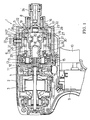
- Fig. 1 is a partial vertical section view showing an example of an impact driver.
- An impact driver 1 has a motor 3 accommodated in a body housing 2.
- a hammer case 5 accommodating a spindle 6 and a hammer 7 is incorporated as a front housing.
- An anvil 8 protrudes at the front of the hammer case 5.
- the reference number 9 denotes a switch and the reference number 10 denotes a trigger.
- a gear housing 11 is provided which axially supports a motor shaft 4 of the motor 3 so as to allow the motor shaft 4 to protrude into the hammer case 5.
- the gear housing 11 axially supports the end of the spindle 6 through a ball bearing 12.
- a pinion 13 is mounted at the top of the motor shaft 4 which is inserted coaxially with play into a hollow portion 14 formed at the end of the spindle 6.
- the motor shaft 4 engages with a plurality of planetary gears 15, 15... which are axially provided at the rear outer circumference of the spindle 6 which receives the rotation speed of the motor shaft 4 with reduction.
- the anvil 8 is axially supported at the front end of the hammer case 5 so as to rotate by means of a bearing 16.
- the spindle 6 has a small-diameter portion 17 inserted coaxially into the end face of the anvil 8 with play.
- the hammer 7 is externally provided.
- the hammer 7 is connected to the spindle 6 so as to be integrally rotatable through two steel balls 20, 20 inserted in a manner that straddle both a pair of cam grooves 18, 18 formed with a slope at the outer circumference of the spindle 6 and a pair of connecting grooves 19, 19 formed in the axial direction at the inner circumference of the hammer 7 respectively.
- the hammer 7 is pressed forward by a coil spring 21 provided externally to the spindle 6 at the rear of the hammer 7.
- a pair of engaging portions 23, 23 is provided so as to engage with a pair of arms 22, 22 extending in the radial direction at the rear end of the anvil 8.
- the reference number 24 denotes a chuck sleeve externally provided at the top of the anvil 8 for locking a driver bit and the like inserted into the anvil 8.
- a connecting sleeve 25 serving as a connecting member is accommodated so as to be movable and rotatable in the axial direction in a manner that is externally provided on the hammer 7 and the anvil 8.
- the connecting sleeve 25 has connecting teeth 26, 26... formed at its inner circumference in the axial direction with even intervals in the circumferential direction.
- the connecting teeth 26, 26... can engage with first engaging teeth 27, 27... formed at the outer circumference of the hammer 7 and second engaging teeth 28, 28... formed at the outer circumference of the arms 22, 22 of the anvil 8, respectively.
- the reference number 29 denotes a coil spring located at the rear of the connecting sleeve 25. The coil spring 29 presses the connecting sleeve 25 to a forward position where it engages with the hammer 7 and the anvil 8 simultaneously.
- a concave groove 30 is formed in the circumferential direction.
- a tip of an operating bolt 33 serving as an operating means, on which sleeves 31, 32 are externally provided and which is penetrating the hammer case 5 is inserted into the concave groove 30. Consequently, the connecting sleeve 25 is regulated its forward position by the operating bolt 33.
- an L-shaped guiding groove 34 is formed in a portion through which the operating bolt 33 penetrates in the hammer case 5.
- the guiding groove 34 consists of a first groove 35 formed in the circumferential direction of the hammer case 5 and a second groove 36 formed in the axial direction which extends from the end of first groove 35.
- the operating bolt 33 with the connecting sleeve 25, which is biased forward by the coil spring 29, can change its position in the axial direction in accordance with its position in the guiding groove 34.
- the reference number 37 denotes a curved slide plate which is positioned between the tip of the operating bolt 33 and the hammer case 5 and with which the head of the operating bolt 33 is threadedly engaged.
- the slide plate 37 slides integrally with the operating bolt 33 at the outer circumference of the hammer case 5 so as to close off the outside of the guide groove 34, thereby preventing intrusion of dust into the hammer case 5.
- the operating bolt 33 with the connecting sleeve 25 is locked at the forward position (a second slide position).
- the connecting tooth 26 of the connecting sleeve 25 engages with the first engaging tooth 27 of the hammer 7 and the second engaging tooth 28 of the anvil 8 simultaneously, whereby the hammer 7 and the anvil 8 are connected to rotate integrally through the connecting sleeve 25 (a drill mode).
- the impact driver 1 when the operating bolt 33 is locked in the engaging concave portion 38 of the first groove 35, the impact mode is selected as shown in Fig. 1 . Then, when the trigger 10 is pressed to turn ON the switch 9 in order to drive the motor 3, the rotation speed of the motor shaft 4 is transferred to the spindle 6 with reduction. As a result, the anvil 8 is rotated through the hammer 7. With this mechanism, screwing can be performed using a driver bit and the like attached at the top of the anvil 8. While this screwing, the connecting sleeve 25 engaged with the hammer 7 also rotates integrally with the spindle 6. In this case, however, the operating bolt 33 is relatively slides in the concave groove 30, so that the connecting sleeve 25 and the hammer 7 are freely rotatable not influenced by the operating bolt 33.
- the connecting sleeve 25 moves forward to connect the hammer 7 and the anvil 8 integrally, so that a torque of the spindle 6 is transferred from the hammer 7 to the anvil 8 through the connecting sleeve 25. Therefore, the anvil 8 keeps rotating at an even speed irrespective of a load on the anvil 8, so that an impact does not occur to the anvil 8 even when the hammer 7 disengages from the anvil 8.
- both boring and screwing can be conducted only with the impact driver, whereby improvement of its operability can be expected.
- the impact driver has a simple structure in which the connection status between the hammer 7 and the anvil 8 is switched using the connecting sleeve 25. Therefore, a drill mode is obtained without fail and enlargement of the hammer case 5 is prevented, and the drill mode is feasible with a low cost.
- the hammer 7 engages with the anvil 8 through the connecting sleeve 25 in an impact mode
- the hammer 7 which is connected with the connecting sleeve 25 engages with the anvil 8, whereby the mass of the hammer 7 itself which moves back and forth can be set to be smaller. As a result, vibration can be reduced in the impact mode, thereby maintaining excellent operability.
- the connecting member is formed as the connecting sleeve 25 having the connecting tooth 26 capable of engaging with the first and second engaging teeth 27, 28 formed at the outer circumference of the hammer 7 and the anvil 8.
- the operating means is formed as the operating bolt 33 inserted into the concave groove 30 provided at the outer circumference of the connecting sleeve 25 through a guide groove 34 formed in the hammer case 5. The operating bolt 33 guides the connecting sleeve 25 to a forward or backward position through its movement in the guide groove 34. In this way, the connecting member and the operating means can be easily obtained.
- the connecting sleeve is biased from backward.
- a coil spring in front of the connecting sleeve in order to press from the front.
- other elastic body such as a plate spring, may be adopted other than the coil spring.
- this kind of biasing means may be omitted as long as the operation bolt can be fixed at a predetermined slide position by modifying the shape of the guide groove or providing other stopper means.
- a pin may be adopted other than the operating bolt and it is not limited to the structure in which the axis member itself is operated.
- a rotating lever having an eccentric pin to be inserted into a concave groove of a connecting sleeve may be attached on a hammer case. With this configuration, it is possible to obtain the axial movement of the eccentric pin by rotative operation of the rotating lever.
- the connecting sleeve may be shortened in the axial direction.
- the connecting member may be located at a slide position for engaging with the anvil only, and then it moves backward to engage with the hammer and the anvil, not limited to the above-described structure in which the connecting member moves forward from a position for engaging with the hammer only.
- the connecting member may be located at a position for engaging with neither the hammer nor the anvil, and then it moves to either of two positions, which are, a position for engaging with each of the hammer or the anvil and a position for engaging with the hammer and the anvil.
Landscapes
- Engineering & Computer Science (AREA)
- Mechanical Engineering (AREA)
- Drilling And Boring (AREA)
- Percussive Tools And Related Accessories (AREA)
Description
- The present invention relates to an impact driver capable of applying rotation and the intermittent impact operation to an anvil protruding to the front of a housing.
- An impact driver has a well-known structure in which a spindle rotated by a motor is connected with a hammer through cam grooves and balls, and an anvil which is locked in the rotative direction is axially provided in front of the hammer, whereby rotation of the spindle is transferred to the anvil through the hammer. With this structure, when a load on the anvil exceeds a predetermined value, the hammer moves backward along the cam grooves to temporarily disengage from the anvil, and thereafter it moves forward by a coil spring biased to the front along the cam grooves to reengage with the anvil. By repeating the above operation, it is possible to apply the intermittent impact operation to the anvil in the rotative direction.
- The above-described impact driver is generally used for screwing with a screw or a bolt etc. Thus, when it is used for boring a shallow hole on a material to be processed, a user has to handle two separate tools in turn, which are, an electric drill and an impact driver. Consequently, it is troublesome to exchange tools and therefore usability might be reduced.
- In order to solve the above problem, Japanese Patent No.
2828640 3372345 - However, Japanese Patent No.
2828640 - Moreover, in Japanese Patent No.
3372345 EP 1 050 381 A2 , which forms the preamble of claim 1 discloses an impact rotary tool for use in an operation to tighten a bolt, a nut and a screw. - In order to solve this problem, an object of the present invention is to provide an impact driver in which selection of a drill mode is feasible with a simpler structure and a usability is excellent.
- In order to achieve the above object, in an aspect of the present invention, a connecting member is provided in a housing so as to be movable between a first slide position where the connecting member engages either a hammer or an anvil so as to rotate integrally with the hammer or the anvil and a second slide position where the connecting member engages both the hammer and the anvil to rotate integrally with both of them. Moreover, an operating means is provided in the housing for moving the connecting member to each of the two slide positions from outside of the housing.
- Further, in order to simply form the connecting member and the operating means, the connecting member is formed as a sleeve having connecting teeth in its inner circumference for engaging with engaging teeth formed at the outer circumference of the anvil and the hammer, and the operating means is formed as an axis member which is inserted into a concave groove provided at the outer circumference of the sleeve through a guide groove formed in the housing and which guides the sleeve to the slide positions through its movement in the guide groove.
- According to the aspect of the present invention, both boring and screwing can be conducted with an impact driver only, whereby improvement of its operability can be expected. In particular, the impact driver has a simple structure in which the connection status between the hammer and the anvil is switched using the connection member. Therefore, a drill mode is obtained without fail and enlargement of the housing is prevented, and the drill mode is feasible with a low cost. Moreover, when the connecting member engages with the hammer at the first slide position to select an impact mode, the hammer which is connected with the connecting member engages with the anvil, whereby the mass of the hammer itself which moves back and forth can be set to be smaller. As a result, vibration can be reduced in the impact mode, thereby maintaining excellent operability.
- Further, the connecting member and the operating means for the same can be simply formed.
-
-
Fig. 1 is a partial vertical section view of an impact driver of the first embodiment (in an impact mode). -
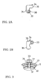
Fig. 2 is an explanation view of a guide groove.Fig. 2A shows a position of an operation bolt in the impact mode andFig. 2B shows a position of the same in a drill mode. -
Fig. 3 is a partial transverse cross section view of a hammer case showing a portion of the operation bolt. -
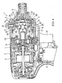
Fig. 4 is a partial vertical section view of an impact driver (in a drill mode). - Hereinafter, a preferred embodiment of the present invention will be explained with reference to the drawings.
-
Fig. 1 is a partial vertical section view showing an example of an impact driver. An impact driver 1 has amotor 3 accommodated in a body housing 2. At the front of the body housing 2, ahammer case 5 accommodating aspindle 6 and ahammer 7 is incorporated as a front housing. Ananvil 8 protrudes at the front of thehammer case 5. Thereference number 9 denotes a switch and thereference number 10 denotes a trigger. Between the body housing 2 and thehammer case 5, agear housing 11 is provided which axially supports amotor shaft 4 of themotor 3 so as to allow themotor shaft 4 to protrude into thehammer case 5. Moreover, the gear housing 11 axially supports the end of thespindle 6 through a ball bearing 12. Apinion 13 is mounted at the top of themotor shaft 4 which is inserted coaxially with play into a hollow portion 14 formed at the end of thespindle 6. In accordance with this structure, themotor shaft 4 engages with a plurality ofplanetary gears spindle 6 which receives the rotation speed of themotor shaft 4 with reduction. - The
anvil 8 is axially supported at the front end of thehammer case 5 so as to rotate by means of abearing 16. At the front end, thespindle 6 has a small-diameter portion 17 inserted coaxially into the end face of theanvil 8 with play. At the rear of the small-diameter portion 17, thehammer 7 is externally provided. Thehammer 7 is connected to thespindle 6 so as to be integrally rotatable through twosteel balls cam grooves spindle 6 and a pair of connectinggrooves hammer 7 respectively. Moreover, thehammer 7 is pressed forward by acoil spring 21 provided externally to thespindle 6 at the rear of thehammer 7. At the front surface of thehammer 7, a pair ofengaging portions arms anvil 8. When thehammer 7 is pressed forward as shown inFig. 1 , theengaging portions arms hammer 7 to be integral with theanvil 8 in the rotative direction. Thereference number 24 denotes a chuck sleeve externally provided at the top of theanvil 8 for locking a driver bit and the like inserted into theanvil 8. - In the
hammer case 5, a connectingsleeve 25 serving as a connecting member is accommodated so as to be movable and rotatable in the axial direction in a manner that is externally provided on thehammer 7 and theanvil 8. The connectingsleeve 25 has connectingteeth teeth engaging teeth hammer 7 and secondengaging teeth arms anvil 8, respectively. Thereference number 29 denotes a coil spring located at the rear of the connectingsleeve 25. Thecoil spring 29 presses the connectingsleeve 25 to a forward position where it engages with thehammer 7 and theanvil 8 simultaneously. - At the outer circumference of the connecting
sleeve 25, aconcave groove 30 is formed in the circumferential direction. A tip of anoperating bolt 33 serving as an operating means, on whichsleeves hammer case 5 is inserted into theconcave groove 30. Consequently, the connectingsleeve 25 is regulated its forward position by the operatingbolt 33. As shown inFig. 2 , in a portion through which theoperating bolt 33 penetrates in thehammer case 5, an L-shaped guidinggroove 34 is formed. The guidinggroove 34 consists of afirst groove 35 formed in the circumferential direction of thehammer case 5 and asecond groove 36 formed in the axial direction which extends from the end offirst groove 35. With this configuration, the operatingbolt 33 with the connectingsleeve 25, which is biased forward by thecoil spring 29, can change its position in the axial direction in accordance with its position in the guidinggroove 34. As shown inFig. 3 , thereference number 37 denotes a curved slide plate which is positioned between the tip of theoperating bolt 33 and thehammer case 5 and with which the head of theoperating bolt 33 is threadedly engaged. Theslide plate 37 slides integrally with the operatingbolt 33 at the outer circumference of thehammer case 5 so as to close off the outside of theguide groove 34, thereby preventing intrusion of dust into thehammer case 5. - In the above configuration, when the operating
bolt 33 is moved to the end of thefirst groove 35 in theguide groove 34 to engage with an engagingconcave portion 38 at the end of thefirst groove 35 as shown inFig. 2A , the operatingbolt 33 with the connectingsleeve 25 is locked at the backward position (a first slide position). As shown inFig. 1 , at the backward position the connectingtooth 26 of the connectingsleeve 25 engages with the first engagingtooth 27 of thehammer 7 only, whereby the connectingsleeve 25 rotates integrally with the hammer 7 (an impact mode). On the other hand, when the operatingbolt 33 is moved to the front end of thesecond groove 36 as shown inFig. 2B , the operatingbolt 33 with the connectingsleeve 25 is locked at the forward position (a second slide position). As shown inFig. 4 , at the forward position, the connectingtooth 26 of the connectingsleeve 25 engages with the first engagingtooth 27 of thehammer 7 and the second engagingtooth 28 of theanvil 8 simultaneously, whereby thehammer 7 and theanvil 8 are connected to rotate integrally through the connecting sleeve 25 (a drill mode). - In the above-structured impact driver 1, when the operating
bolt 33 is locked in the engagingconcave portion 38 of thefirst groove 35, the impact mode is selected as shown inFig. 1 . Then, when thetrigger 10 is pressed to turn ON theswitch 9 in order to drive themotor 3, the rotation speed of themotor shaft 4 is transferred to thespindle 6 with reduction. As a result, theanvil 8 is rotated through thehammer 7. With this mechanism, screwing can be performed using a driver bit and the like attached at the top of theanvil 8. While this screwing, the connectingsleeve 25 engaged with thehammer 7 also rotates integrally with thespindle 6. In this case, however, the operatingbolt 33 is relatively slides in theconcave groove 30, so that the connectingsleeve 25 and thehammer 7 are freely rotatable not influenced by the operatingbolt 33. - When screwing proceeds to a state in which a load on the
anvil 8 increases, thesteel balls cam grooves spindle 6. Consequently, thehammer 7 is moved backward against the biasing force of thecoil spring 21 until it disengages from theanvil 8. However, at the moment of this disengagement thehammer 7, which is rotating with thespindle 6, immediately moves forward again being pressed by thecoil spring 21 until the engagingportions arms anvil 8. These disengagement and reengagement of thehammer 7 with respect to theanvil 8 are mechanically repeated, which leads to the intermittent impact operation to theanvil 8 in the rotative direction. In this way, tight screwing can be conducted. It should be noted that even when thehammer 7 moves back and forth, the engagement situation of the connectingtooth 26 of the connectingsleeve 25 is maintained, so that the connectingsleeve 25 always rotates integrally with thehammer 7. - On the other hand, when the drill mode is selected by moving the
operating bolt 33 to the front end of thesecond groove 36 as shown inFig. 4 , the connectingsleeve 25 moves forward to connect thehammer 7 and theanvil 8 integrally, so that a torque of thespindle 6 is transferred from thehammer 7 to theanvil 8 through the connectingsleeve 25. Therefore, theanvil 8 keeps rotating at an even speed irrespective of a load on theanvil 8, so that an impact does not occur to theanvil 8 even when thehammer 7 disengages from theanvil 8. - In the impact driver 1, both boring and screwing can be conducted only with the impact driver, whereby improvement of its operability can be expected. In particular, the impact driver has a simple structure in which the connection status between the
hammer 7 and theanvil 8 is switched using the connectingsleeve 25. Therefore, a drill mode is obtained without fail and enlargement of thehammer case 5 is prevented, and the drill mode is feasible with a low cost. Moreover, when thehammer 7 engages with theanvil 8 through the connectingsleeve 25 in an impact mode, thehammer 7 which is connected with the connectingsleeve 25 engages with theanvil 8, whereby the mass of thehammer 7 itself which moves back and forth can be set to be smaller. As a result, vibration can be reduced in the impact mode, thereby maintaining excellent operability. - Moreover, the connecting member is formed as the connecting
sleeve 25 having the connectingtooth 26 capable of engaging with the first and second engagingteeth hammer 7 and theanvil 8. On the other hand, the operating means is formed as the operatingbolt 33 inserted into theconcave groove 30 provided at the outer circumference of the connectingsleeve 25 through aguide groove 34 formed in thehammer case 5. The operatingbolt 33 guides the connectingsleeve 25 to a forward or backward position through its movement in theguide groove 34. In this way, the connecting member and the operating means can be easily obtained. - In the embodiment, the connecting sleeve is biased from backward. Alternatively, it is acceptable to provide a coil spring in front of the connecting sleeve in order to press from the front. Moreover, other elastic body, such as a plate spring, may be adopted other than the coil spring. Further, this kind of biasing means may be omitted as long as the operation bolt can be fixed at a predetermined slide position by modifying the shape of the guide groove or providing other stopper means.
- With respect to the axis member, a pin may be adopted other than the operating bolt and it is not limited to the structure in which the axis member itself is operated. For example, a rotating lever having an eccentric pin to be inserted into a concave groove of a connecting sleeve may be attached on a hammer case. With this configuration, it is possible to obtain the axial movement of the eccentric pin by rotative operation of the rotating lever.
- With respect to the connecting member, the connecting sleeve may be shortened in the axial direction. Further, the connecting member may be located at a slide position for engaging with the anvil only, and then it moves backward to engage with the hammer and the anvil, not limited to the above-described structure in which the connecting member moves forward from a position for engaging with the hammer only. Still further, the connecting member may be located at a position for engaging with neither the hammer nor the anvil, and then it moves to either of two positions, which are, a position for engaging with each of the hammer or the anvil and a position for engaging with the hammer and the anvil.
- It is explicitly stated that all value ranges or indications of groups of entities disclose every possible intermediate value or intermediate entity for the purpose of original disclosure as well as for the purpose of restricting the claimed invention, in particular as limits of value ranges.
Claims (6)
- An impact driver(1) comprising:a motor(3) housed in a housing(2);a spindle(6) driven by the motor(3) to rotate;an anvil(8) protruding forward and supported in the housing(2) so as to be rotatable,a hammer(7) provided with the spindle (6) at the rear of the anvil(8) for engaging with the anvil(8) and transferring rotation of the spindle(6) to the anvil(8),wherein the hammer(7) engages with or disengages from the anvil (8) in accordance with a load on the anvil (8), which leads to intermittent impact operation to the anvil(8) in the rotative direction,a connecting member (25) provided in the housing(2) so as to be movable between a first slide position and a second slide position, andan operating means provided in the housing(2) for moving the connecting member to the first or second slide position from outside of the housing(2),wherein an impact mode where the impact operation occurs to the anvil(8) is obtained when the first slide position of the connecting member is selected by the operating means, and a drill mode where the impact operation is stopped irrespective of a load on the anvil(8) is obtained when the second slide position of the connecting member is selected,
characterized in that
engagement with either the hammer(7) or the anvil(8) is achieved in the first slide position in order to rotate integrally with the hammer(7) or the anvil(8) and engagement with both the hammer(7) and the anvil(8) is achieved in the second slide position in order to rotate integrally with both of them, and
engaging teeth(27, 28) are formed at the outer circumference of the anvil(8) and the hammer(7), and the connecting member is formed as a sleeve(25) having a larger diameter than the hammer(7) and the anvil(8) and provided with connecting teeth(26, 26) in its inner circumference for engaging with the engaging teeth(27, 28), and the sleeve(25) is slid in the axial direction to move to the first slide position and the second slide position. - An impact driver(1) in accordance with claim 1, characterized in that engagement of the anvil(8) and the hammer(7) is achieved by a pair of arms(22, 22) extending in the radial direction at the rear end of the anvil(8) and a pair of engaging portions(23, 23) provided at the front surface of the hammer(7).
- An impact driver(1) in accordance with claim 1 or 2, characterized in that the operating means is an axis member(33) which is inserted into a concave groove(30) provided at the outer circumference of the sleeve(25) through a guide groove(34) formed in the housing(2) and which guides the sleeve(25) to the slide positions through movement in the guide groove(34).
- An impact driver(1) in accordance with claim 3, characterized in that the axis member(33) has a slide plate(37) provided integrally for sliding on the outer circumference of the housing(2) in accordance with the operation of the axis member(33) so as to close off the outside of the guide groove(34).
- An impact driver(1) in accordance with claim 3, characterized in that the guide groove(34) is formed into an L-shape consisting of a first groove(35) provided in the circumferential direction of the housing(2) and a second groove(36) extending sequentially from the end of the first groove(35) in the longitudinal direction,
and wherein the first slide position of the sleeve(25) is selected when the axis member(33) is positioned in the first groove(35), and the second slide position of the sleeve(25) is selected when the axis member(33) is positioned in the front end of the second groove(36). - An impact driver(1) in accordance with claim 5, characterized in that a biasing means for pressing the axis member(33) with the sleeve(25) to the front end side of the second groove(36) is provided.
Applications Claiming Priority (4)
| Application Number | Priority Date | Filing Date | Title |
|---|---|---|---|
| JP2004068046 | 2004-03-10 | ||
| JP2004068046 | 2004-03-10 | ||
| JP2004349000 | 2004-12-01 | ||
| JP2004349000A JP4405900B2 (en) | 2004-03-10 | 2004-12-01 | Impact driver |
Publications (3)
| Publication Number | Publication Date |
|---|---|
| EP1574294A2 EP1574294A2 (en) | 2005-09-14 |
| EP1574294A3 EP1574294A3 (en) | 2007-06-06 |
| EP1574294B1 true EP1574294B1 (en) | 2010-07-07 |
Family
ID=34829503
Family Applications (1)
| Application Number | Title | Priority Date | Filing Date |
|---|---|---|---|
| EP05005051A Expired - Lifetime EP1574294B1 (en) | 2004-03-10 | 2005-03-08 | Impact driver |
Country Status (4)
| Country | Link |
|---|---|
| US (1) | US7124839B2 (en) |
| EP (1) | EP1574294B1 (en) |
| JP (1) | JP4405900B2 (en) |
| DE (1) | DE602005022137D1 (en) |
Cited By (3)
| Publication number | Priority date | Publication date | Assignee | Title |
|---|---|---|---|---|
| CN101786266B (en) * | 2009-01-27 | 2012-06-27 | 松下电工电动工具株式会社 | Rotary impact tool |
| CN102729222A (en) * | 2011-04-05 | 2012-10-17 | 株式会社牧田 | Power tool |
| CN103153547A (en) * | 2010-10-20 | 2013-06-12 | 罗伯特·博世有限公司 | Power drill |
Families Citing this family (112)
| Publication number | Priority date | Publication date | Assignee | Title |
|---|---|---|---|---|
| JP4291173B2 (en) * | 2004-02-10 | 2009-07-08 | 株式会社マキタ | Impact driver |
| US7308948B2 (en) * | 2004-10-28 | 2007-12-18 | Makita Corporation | Electric power tool |
| US20060213675A1 (en) * | 2005-03-24 | 2006-09-28 | Whitmire Jason P | Combination drill |
| CN101267906B (en) * | 2005-08-29 | 2010-11-03 | 迪美科技控股有限公司 | electrical tools |
| US7942211B2 (en) * | 2005-08-29 | 2011-05-17 | Demain Technology, Pty Ltd | Power tool |
| DE102005041448A1 (en) * | 2005-08-31 | 2007-03-01 | Robert Bosch Gmbh | Hammer drill, comprises manually operated switch with outer shell and sealing ring |
| JP2007068550A (en) * | 2005-09-02 | 2007-03-22 | Olympus Medical Systems Corp | Medical equipment |
| US7410007B2 (en) * | 2005-09-13 | 2008-08-12 | Eastway Fair Company Limited | Impact rotary tool with drill mode |
| JP4757043B2 (en) * | 2006-01-27 | 2011-08-24 | 株式会社マキタ | Work tools |
| EP2004362A4 (en) | 2006-03-23 | 2010-09-29 | Demain Technology Pty Ltd | A power tool guard |
| WO2008033366A2 (en) * | 2006-09-12 | 2008-03-20 | Black & Decker Inc. | Driver with external torque value indicator integrated with spindle lock and related method |
| US7578357B2 (en) * | 2006-09-12 | 2009-08-25 | Black & Decker Inc. | Driver with external torque value indicator integrated with spindle lock and related method |
| DE102007003037A1 (en) * | 2007-01-20 | 2008-07-24 | Protool Gmbh | impact wrench |
| JP2008183633A (en) * | 2007-01-26 | 2008-08-14 | Makita Corp | Hammer drill |
| EP1961522B1 (en) * | 2007-02-23 | 2015-04-08 | Robert Bosch Gmbh | Rotary power tool operable in either an impact mode or a drill mode |
| EP1970165A1 (en) * | 2007-03-12 | 2008-09-17 | Robert Bosch Gmbh | A rotary power tool operable in a first speed mode and a second speed mode |
| CN101288950B (en) * | 2007-04-18 | 2011-08-03 | 苏州宝时得电动工具有限公司 | Multifunctional power tool |
| WO2008157346A1 (en) | 2007-06-15 | 2008-12-24 | Black & Decker Inc. | Hybrid impact tool |
| CN101342693B (en) * | 2007-07-12 | 2011-08-03 | 苏州宝时得电动工具有限公司 | Power tool |
| EP2180979B1 (en) * | 2007-08-20 | 2011-06-08 | Metabowerke GmbH | Electric handheld power tool |
| CN101402190B (en) * | 2007-10-01 | 2012-04-25 | 苏州宝时得电动工具有限公司 | Dynamic tool |
| CN101407053B (en) * | 2007-10-09 | 2011-06-29 | 苏州宝时得电动工具有限公司 | Power tool |
| DE102007050307A1 (en) * | 2007-10-22 | 2009-04-23 | Robert Bosch Gmbh | Hand tool |
| US7717192B2 (en) | 2007-11-21 | 2010-05-18 | Black & Decker Inc. | Multi-mode drill with mode collar |
| US7854274B2 (en) * | 2007-11-21 | 2010-12-21 | Black & Decker Inc. | Multi-mode drill and transmission sub-assembly including a gear case cover supporting biasing |
| US7717191B2 (en) * | 2007-11-21 | 2010-05-18 | Black & Decker Inc. | Multi-mode hammer drill with shift lock |
| US7798245B2 (en) | 2007-11-21 | 2010-09-21 | Black & Decker Inc. | Multi-mode drill with an electronic switching arrangement |
| US7735575B2 (en) | 2007-11-21 | 2010-06-15 | Black & Decker Inc. | Hammer drill with hard hammer support structure |
| US7770660B2 (en) | 2007-11-21 | 2010-08-10 | Black & Decker Inc. | Mid-handle drill construction and assembly process |
| US7762349B2 (en) | 2007-11-21 | 2010-07-27 | Black & Decker Inc. | Multi-speed drill and transmission with low gear only clutch |
| TWM332537U (en) * | 2007-12-18 | 2008-05-21 | Power Network Industry Co Ltd | Switching device for output configuration |
| CN101497190B (en) * | 2008-01-31 | 2012-03-28 | 苏州宝时得电动工具有限公司 | Electric tool |
| JP5270197B2 (en) * | 2008-03-10 | 2013-08-21 | 株式会社マキタ | Impact tool |
| US20090229397A1 (en) * | 2008-03-16 | 2009-09-17 | Ting-Kuang Chen | Protection Device For Speed Shifting Mechanism |
| CN102015169B (en) * | 2008-04-22 | 2013-12-11 | 杰勒德·格兰特 | Impact mechanism |
| CN201201225Y (en) * | 2008-05-20 | 2009-03-04 | 东莞群胜粉末冶金有限公司 | Impact switching mechanism of impact drill |
| JP5176709B2 (en) * | 2008-06-13 | 2013-04-03 | 日立工機株式会社 | Rotating hammer tool |
| EP2140976B1 (en) | 2008-07-01 | 2011-11-16 | Metabowerke GmbH | Impact wrench |
| ATE554883T1 (en) * | 2008-07-01 | 2012-05-15 | Metabowerke Gmbh | IMPACT WRENCH |
| AU2009279632B2 (en) | 2008-08-06 | 2013-09-26 | Milwaukee Electric Tool Corporation | Precision torque tool |
| TWI350236B (en) * | 2008-08-20 | 2011-10-11 | Bo Shen Chen | Power tool connector with imapct and vibration function |
| US9193053B2 (en) * | 2008-09-25 | 2015-11-24 | Black & Decker Inc. | Hybrid impact tool |
| US8251158B2 (en) | 2008-11-08 | 2012-08-28 | Black & Decker Inc. | Multi-speed power tool transmission with alternative ring gear configuration |
| CN101786179B (en) * | 2009-01-23 | 2012-01-04 | 车王电子(宁波)有限公司 | Electric tool |
| US8631880B2 (en) * | 2009-04-30 | 2014-01-21 | Black & Decker Inc. | Power tool with impact mechanism |
| TWM367039U (en) * | 2009-06-17 | 2009-10-21 | Top Gearbox Industry Co Ltd | Output style-switching device |
| JP5284898B2 (en) * | 2009-07-21 | 2013-09-11 | 株式会社マキタ | Impact tool |
| CN102019608B (en) * | 2009-09-10 | 2013-07-03 | 苏州宝时得电动工具有限公司 | Power tool |
| JP5340881B2 (en) * | 2009-10-16 | 2013-11-13 | 株式会社マキタ | Impact tool |
| DE102009054931A1 (en) * | 2009-12-18 | 2011-06-22 | Robert Bosch GmbH, 70469 | Hand-held power tool with a torque coupling |
| US8460153B2 (en) * | 2009-12-23 | 2013-06-11 | Black & Decker Inc. | Hybrid impact tool with two-speed transmission |
| CN102844154B (en) * | 2010-02-19 | 2015-09-16 | 密尔沃基电动工具公司 | Percussion mechanism |
| JP5483086B2 (en) * | 2010-02-22 | 2014-05-07 | 日立工機株式会社 | Impact tools |
| US8584770B2 (en) | 2010-03-23 | 2013-11-19 | Black & Decker Inc. | Spindle bearing arrangement for a power tool |
| JP2012006101A (en) * | 2010-06-23 | 2012-01-12 | Makita Corp | Impact tool |
| CN102971113B (en) | 2010-06-30 | 2015-03-25 | 日立工机株式会社 | Impact tool |
| JP5583500B2 (en) * | 2010-07-05 | 2014-09-03 | 株式会社マキタ | Impact tool |
| DE102010031499A1 (en) * | 2010-07-19 | 2012-01-19 | Robert Bosch Gmbh | Hand tool with a mechanical percussion |
| CN102335904B (en) * | 2010-07-20 | 2014-04-16 | 苏州宝时得电动工具有限公司 | Power tool |
| CN102335907B (en) * | 2010-07-20 | 2014-04-16 | 苏州宝时得电动工具有限公司 | power tool |
| WO2012061176A2 (en) * | 2010-11-04 | 2012-05-10 | Milwaukee Electric Tool Corporation | Impact tool with adjustable clutch |
| DE102010062099A1 (en) * | 2010-11-29 | 2012-05-31 | Robert Bosch Gmbh | Hammer mechanism |
| DE102010062107A1 (en) * | 2010-11-29 | 2012-05-31 | Robert Bosch Gmbh | Hammer mechanism |
| DE102011017671A1 (en) * | 2011-04-28 | 2012-10-31 | Hilti Aktiengesellschaft | Hand tool |
| JP5468570B2 (en) * | 2011-06-17 | 2014-04-09 | 株式会社マキタ | Impact tool |
| JP2013094864A (en) * | 2011-10-31 | 2013-05-20 | Hitachi Koki Co Ltd | Impact tool |
| DE102011089910A1 (en) * | 2011-12-27 | 2013-06-27 | Robert Bosch Gmbh | Hand tool device |
| DE102011089914A1 (en) * | 2011-12-27 | 2013-06-27 | Robert Bosch Gmbh | Hand tool device |
| DE102012212417B4 (en) * | 2012-07-16 | 2017-06-08 | Robert Bosch Gmbh | switching unit |
| US9630307B2 (en) | 2012-08-22 | 2017-04-25 | Milwaukee Electric Tool Corporation | Rotary hammer |
| WO2014075165A1 (en) * | 2012-11-14 | 2014-05-22 | British Columbia Cancer Agency Branch | Cannulated hammer drill attachment |
| JP6050110B2 (en) | 2012-12-27 | 2016-12-21 | 株式会社マキタ | Impact tools |
| CN103944419B (en) * | 2013-01-17 | 2016-07-06 | 北京大风时代科技有限责任公司 | Power-type multiplication of voltage drive circuit and use the electric driver of this power-type multiplication of voltage drive circuit |
| JP2015024474A (en) * | 2013-07-26 | 2015-02-05 | 日立工機株式会社 | Impact tool |
| KR102121094B1 (en) * | 2013-08-08 | 2020-06-17 | 아틀라스 콥코 인더스트리얼 테크니크 에이비 | Torque delivering power tool with flywheel |
| EP2835198A1 (en) * | 2013-08-09 | 2015-02-11 | HILTI Aktiengesellschaft | Intuitive, adaptive spot drilling function |
| CN104608100B (en) * | 2013-11-04 | 2017-04-19 | 南京德朔实业有限公司 | Multipurpose electric tool and control method thereof |
| JP2015120206A (en) * | 2013-12-20 | 2015-07-02 | 日立工機株式会社 | Impact tool |
| CN105437129B (en) * | 2014-06-30 | 2017-04-19 | 南京德朔实业有限公司 | Torsion force output tool |
| US9908232B2 (en) * | 2014-06-30 | 2018-03-06 | Chervon (Hk) Limited | Torsion output tool |
| GB201421576D0 (en) | 2014-12-04 | 2015-01-21 | Black & Decker Inc | Drill |
| GB201421577D0 (en) * | 2014-12-04 | 2015-01-21 | Black & Decker Inc | Drill |
| DE102015201573A1 (en) * | 2015-01-29 | 2016-08-04 | Robert Bosch Gmbh | Impact device, in particular for an impact wrench |
| US10404136B2 (en) * | 2015-10-14 | 2019-09-03 | Black & Decker Inc. | Power tool with separate motor case compartment |
| US10471573B2 (en) | 2016-01-05 | 2019-11-12 | Milwaukee Electric Tool Corporation | Impact tool |
| DE102017211772A1 (en) * | 2016-07-11 | 2018-01-11 | Robert Bosch Gmbh | Hand machine tool device |
| CN109129342A (en) * | 2017-06-28 | 2019-01-04 | 苏州宝时得电动工具有限公司 | Multi-functional drill |
| JP6832509B2 (en) * | 2017-03-27 | 2021-02-24 | パナソニックIpマネジメント株式会社 | Rotary striking tool |
| US10744632B2 (en) * | 2017-11-29 | 2020-08-18 | Nanjing Chervon Industry Co., Ltd. | Power tool |
| CN108747942A (en) * | 2018-07-24 | 2018-11-06 | 苏州多维思智能科技有限公司 | High stability electric screwdriver |
| AU2019101751B4 (en) * | 2018-02-19 | 2025-11-27 | Milwaukee Electric Tool Corporation | Impact tool |
| US10654114B2 (en) * | 2018-06-08 | 2020-05-19 | Lockheed Martin Corporation | Micro-peck feed drill clutch |
| US11213934B2 (en) | 2018-07-18 | 2022-01-04 | Milwaukee Electric Tool Corporation | Impulse driver |
| WO2020132587A1 (en) * | 2018-12-21 | 2020-06-25 | Milwaukee Electric Tool Corporation | High torque impact tool |
| CN118906007A (en) * | 2019-08-16 | 2024-11-08 | 米沃奇电动工具公司 | Mode selection for power tools |
| CN211805940U (en) | 2019-09-20 | 2020-10-30 | 米沃奇电动工具公司 | Impact tool and hammer head |
| CN112720366A (en) * | 2019-10-29 | 2021-04-30 | 苏州宝时得电动工具有限公司 | Hand tool |
| CN112720367B (en) * | 2019-10-29 | 2024-04-30 | 苏州宝时得电动工具有限公司 | Hand-held tool |
| US11964375B2 (en) | 2019-11-27 | 2024-04-23 | Black & Dekcer Inc. | Power tool with multispeed transmission |
| CN110768459B (en) * | 2019-12-09 | 2021-05-14 | 深圳市大科电机有限公司 | Permanent magnet brushless direct current planetary gear speed reduction motor |
| US11724368B2 (en) * | 2020-09-28 | 2023-08-15 | Milwaukee Electric Tool Corporation | Impulse driver |
| US12325112B2 (en) | 2020-09-28 | 2025-06-10 | Milwaukee Electric Tool Corporation | Power tool with impulse assembly including a valve |
| JP2022158636A (en) * | 2021-04-02 | 2022-10-17 | 株式会社マキタ | Electric power tool and impact tool |
| JP7696237B2 (en) * | 2021-06-10 | 2025-06-20 | 株式会社マキタ | Rotary impact tool |
| JP7762058B2 (en) * | 2021-12-17 | 2025-10-29 | 株式会社マキタ | Impact tools |
| EP4234168A1 (en) * | 2022-02-28 | 2023-08-30 | Hilti Aktiengesellschaft | Impact wrench with damper |
| JP7783781B2 (en) * | 2022-05-16 | 2025-12-10 | 株式会社マキタ | Impact tools |
| JP7825526B2 (en) * | 2022-07-06 | 2026-03-06 | 株式会社マキタ | Hammer drill |
| WO2024020476A1 (en) * | 2022-07-20 | 2024-01-25 | Milwaukee Electric Tool Corporation | Outer ring drive planetary gear assembly |
| US12539590B2 (en) * | 2023-01-12 | 2026-02-03 | Milwaukee Electric Tool Corporation | Printed circuit board assembly with multiple conduction paths |
| USD1090213S1 (en) | 2023-10-26 | 2025-08-26 | Snap-On Incorporated | Tool housing |
| EP4670913A1 (en) * | 2024-06-25 | 2025-12-31 | Nanjing Chervon Industry Co., Ltd. | IMPACT WRENCH AND POWER TOOLS |
Family Cites Families (21)
| Publication number | Priority date | Publication date | Assignee | Title |
|---|---|---|---|---|
| US3736992A (en) * | 1971-07-14 | 1973-06-05 | Black & Decker Mfg Co | Control collar and bearing support for power tool shaft |
| IT1066884B (en) * | 1976-08-09 | 1985-03-12 | Star Utensili Elett | DRILL OF THE PERCUSSION TYPE |
| JPS5969808U (en) * | 1982-09-07 | 1984-05-11 | 株式会社マキタ | Vibratory device in vibrating drill |
| JP2828640B2 (en) | 1988-11-15 | 1998-11-25 | 松下電工株式会社 | Rotary impact tool |
| DE4328599C2 (en) * | 1992-08-25 | 1998-01-29 | Makita Corp | Rotary striking tool |
| DE4301610C2 (en) * | 1993-01-22 | 1996-08-14 | Bosch Gmbh Robert | Impact wrench |
| GB9304540D0 (en) * | 1993-03-05 | 1993-04-21 | Black & Decker Inc | Power tool and mechanism |
| JP3372345B2 (en) | 1993-05-26 | 2003-02-04 | 松下電工株式会社 | Impact rotary tool |
| US5531278A (en) * | 1995-07-07 | 1996-07-02 | Lin; Pi-Chu | Power drill with drill bit unit capable of providing intermittent axial impact |
| JP3424880B2 (en) * | 1995-08-18 | 2003-07-07 | 株式会社マキタ | Hammer drill |
| JP3582760B2 (en) * | 1997-04-18 | 2004-10-27 | 日立工機株式会社 | Hammer drill |
| DE19717712A1 (en) * | 1997-04-18 | 1998-10-22 | Black & Decker Inc | Hammer drill |
| US6142242A (en) * | 1999-02-15 | 2000-11-07 | Makita Corporation | Percussion driver drill, and a changeover mechanism for changing over a plurality of operating modes of an apparatus |
| JP3911905B2 (en) * | 1999-04-30 | 2007-05-09 | 松下電工株式会社 | Impact rotary tool |
| JP3688943B2 (en) * | 1999-08-26 | 2005-08-31 | 株式会社マキタ | Hammer drill |
| DE10205030A1 (en) * | 2002-02-07 | 2003-08-21 | Hilti Ag | Operating mode switching unit of a hand machine tool |
| WO2004020156A1 (en) * | 2002-08-27 | 2004-03-11 | Matsushita Electric Works, Ltd. | Electrically operated vibrating drill/driver |
| GB2394517A (en) * | 2002-10-23 | 2004-04-28 | Black & Decker Inc | Powered hammer having a spindle lock with synchronising element |
| TW554792U (en) * | 2003-01-29 | 2003-09-21 | Mobiletron Electronics Co Ltd | Function switching device of electric tool |
| TW556637U (en) * | 2003-02-24 | 2003-10-01 | Mobiletron Electronics Co Ltd | Power tool |
| US7308948B2 (en) * | 2004-10-28 | 2007-12-18 | Makita Corporation | Electric power tool |
-
2004
- 2004-12-01 JP JP2004349000A patent/JP4405900B2/en not_active Expired - Fee Related
-
2005
- 2005-03-03 US US11/070,161 patent/US7124839B2/en not_active Expired - Lifetime
- 2005-03-08 EP EP05005051A patent/EP1574294B1/en not_active Expired - Lifetime
- 2005-03-08 DE DE602005022137T patent/DE602005022137D1/en not_active Expired - Lifetime
Cited By (5)
| Publication number | Priority date | Publication date | Assignee | Title |
|---|---|---|---|---|
| CN101786266B (en) * | 2009-01-27 | 2012-06-27 | 松下电工电动工具株式会社 | Rotary impact tool |
| CN103153547A (en) * | 2010-10-20 | 2013-06-12 | 罗伯特·博世有限公司 | Power drill |
| CN103153547B (en) * | 2010-10-20 | 2016-06-08 | 罗伯特·博世有限公司 | Rig |
| CN102729222A (en) * | 2011-04-05 | 2012-10-17 | 株式会社牧田 | Power tool |
| CN102729222B (en) * | 2011-04-05 | 2014-06-04 | 株式会社牧田 | Power tool |
Also Published As
| Publication number | Publication date |
|---|---|
| US20050199404A1 (en) | 2005-09-15 |
| JP4405900B2 (en) | 2010-01-27 |
| US7124839B2 (en) | 2006-10-24 |
| EP1574294A3 (en) | 2007-06-06 |
| DE602005022137D1 (en) | 2010-08-19 |
| JP2005288682A (en) | 2005-10-20 |
| EP1574294A2 (en) | 2005-09-14 |
Similar Documents
| Publication | Publication Date | Title |
|---|---|---|
| EP1574294B1 (en) | Impact driver | |
| EP1563960B1 (en) | Impact driver having a percussion application mechanism which operation mode can be selectively switched between percussion and non-percussion mode | |
| JP4673118B2 (en) | Hammer drill equipment | |
| JP5468570B2 (en) | Impact tool | |
| EP2103390B1 (en) | Impact wrench with switching member for selecting a drill mode or an impact mode | |
| US7735575B2 (en) | Hammer drill with hard hammer support structure | |
| US6510903B2 (en) | Combination electrical hand-held tool | |
| US7712546B2 (en) | Power tool having torque limiter | |
| JP5340881B2 (en) | Impact tool | |
| JP4536179B2 (en) | Handheld power tool machine | |
| EP1759792B1 (en) | Power driver with dead spindle chucking system with sliding sleve | |
| US7669507B2 (en) | Tightening tool | |
| CN102476367B (en) | Power tool | |
| JP4552843B2 (en) | Hammer tool adapter | |
| JP4597849B2 (en) | Rotating hammer tool | |
| US7188557B2 (en) | Tightening tool | |
| CN211053606U (en) | Impact electric drill | |
| JP2009078317A (en) | Rotating hammer tool |
Legal Events
| Date | Code | Title | Description |
|---|---|---|---|
| PUAI | Public reference made under article 153(3) epc to a published international application that has entered the european phase |
Free format text: ORIGINAL CODE: 0009012 |
|
| 17P | Request for examination filed |
Effective date: 20050308 |
|
| AK | Designated contracting states |
Kind code of ref document: A2 Designated state(s): AT BE BG CH CY CZ DE DK EE ES FI FR GB GR HU IE IS IT LI LT LU MC NL PL PT RO SE SI SK TR |
|
| AX | Request for extension of the european patent |
Extension state: AL BA HR LV MK YU |
|
| PUAL | Search report despatched |
Free format text: ORIGINAL CODE: 0009013 |
|
| AK | Designated contracting states |
Kind code of ref document: A3 Designated state(s): AT BE BG CH CY CZ DE DK EE ES FI FR GB GR HU IE IS IT LI LT LU MC NL PL PT RO SE SI SK TR |
|
| AX | Request for extension of the european patent |
Extension state: AL BA HR LV MK YU |
|
| AKX | Designation fees paid |
Designated state(s): DE FR GB |
|
| 17Q | First examination report despatched |
Effective date: 20090113 |
|
| GRAP | Despatch of communication of intention to grant a patent |
Free format text: ORIGINAL CODE: EPIDOSNIGR1 |
|
| GRAS | Grant fee paid |
Free format text: ORIGINAL CODE: EPIDOSNIGR3 |
|
| GRAA | (expected) grant |
Free format text: ORIGINAL CODE: 0009210 |
|
| AK | Designated contracting states |
Kind code of ref document: B1 Designated state(s): DE FR GB |
|
| REG | Reference to a national code |
Ref country code: GB Ref legal event code: FG4D |
|
| REF | Corresponds to: |
Ref document number: 602005022137 Country of ref document: DE Date of ref document: 20100819 Kind code of ref document: P |
|
| PLBE | No opposition filed within time limit |
Free format text: ORIGINAL CODE: 0009261 |
|
| STAA | Information on the status of an ep patent application or granted ep patent |
Free format text: STATUS: NO OPPOSITION FILED WITHIN TIME LIMIT |
|
| 26N | No opposition filed |
Effective date: 20110408 |
|
| REG | Reference to a national code |
Ref country code: DE Ref legal event code: R097 Ref document number: 602005022137 Country of ref document: DE Effective date: 20110408 |
|
| REG | Reference to a national code |
Ref country code: FR Ref legal event code: PLFP Year of fee payment: 12 |
|
| REG | Reference to a national code |
Ref country code: FR Ref legal event code: PLFP Year of fee payment: 13 |
|
| REG | Reference to a national code |
Ref country code: FR Ref legal event code: PLFP Year of fee payment: 14 |
|
| PGFP | Annual fee paid to national office [announced via postgrant information from national office to epo] |
Ref country code: DE Payment date: 20240130 Year of fee payment: 20 Ref country code: GB Payment date: 20240201 Year of fee payment: 20 |
|
| PGFP | Annual fee paid to national office [announced via postgrant information from national office to epo] |
Ref country code: FR Payment date: 20240213 Year of fee payment: 20 |
|
| REG | Reference to a national code |
Ref country code: DE Ref legal event code: R071 Ref document number: 602005022137 Country of ref document: DE |
|
| REG | Reference to a national code |
Ref country code: GB Ref legal event code: PE20 Expiry date: 20250307 |
|
| PG25 | Lapsed in a contracting state [announced via postgrant information from national office to epo] |
Ref country code: GB Free format text: LAPSE BECAUSE OF EXPIRATION OF PROTECTION Effective date: 20250307 |