CN102729222B - Power tool - Google Patents
Power tool Download PDFInfo
- Publication number
- CN102729222B CN102729222B CN201210094049.9A CN201210094049A CN102729222B CN 102729222 B CN102729222 B CN 102729222B CN 201210094049 A CN201210094049 A CN 201210094049A CN 102729222 B CN102729222 B CN 102729222B
- Authority
- CN
- China
- Prior art keywords
- gear
- pin
- box
- internal gear
- cam
- Prior art date
- Legal status (The legal status is an assumption and is not a legal conclusion. Google has not performed a legal analysis and makes no representation as to the accuracy of the status listed.)
- Active
Links
Images


Classifications
-
- B—PERFORMING OPERATIONS; TRANSPORTING
- B25—HAND TOOLS; PORTABLE POWER-DRIVEN TOOLS; MANIPULATORS
- B25F—COMBINATION OR MULTI-PURPOSE TOOLS NOT OTHERWISE PROVIDED FOR; DETAILS OR COMPONENTS OF PORTABLE POWER-DRIVEN TOOLS NOT PARTICULARLY RELATED TO THE OPERATIONS PERFORMED AND NOT OTHERWISE PROVIDED FOR
- B25F5/00—Details or components of portable power-driven tools not particularly related to the operations performed and not otherwise provided for
- B25F5/001—Gearings, speed selectors, clutches or the like specially adapted for rotary tools
Abstract
The present invention provides a kind of electric tool, and the assembling of the combination and internal gear that make motor bracket and gear-box jointly carries out, to simplify the shape of gear-box and can maintain rigidity. It utilizes across the board (24) for being set to motor bracket (8), (24) be set to first gear case (9) protrusion (26), (26) mode penetrates through board (24), (24) with protrusion (26), (26) a pair of pin (28), (28), to carry out the combination of motor bracket (8) and first gear case (9), and, by making pin (28), (28) engage with the corner portion (29) of the internal gear (23A) of the first order of planetary gear reducing mechanism (20) and flange part (30) to limit the rotation of internal gear (23A) and carry out axial positioning.
Description
Technical field
The present invention relates to there is the electric tools such as the vibrations bottle opener electric drill of motor and planetary gear reducing mechanism.
Background technology
In the electric tool of vibrations bottle opener electric drill, be known to as lower device: at the front distributing planetary gear reducing gear that is accommodated in the motor in housing, the rotation of the output shaft of motor is slowed down and can export to main shaft.The assembling of this motor and planetary gear reducing mechanism adopts following structure,, is installed on the structure that the motor bracket of tubular of motor and the gear-box of the tubular of storage planetary gear reducing mechanism link that is.As this link structure, except known bayonet socket combination, be also known to example and construct as disclosed in Patent Document 1,, make pin run through respectively the intersection of the left and right of motor bracket and gear-box, and utilize the pin of left and right make motor bracket and gear-box integrated.
Patent documentation 1: No. 7066691 description of United States Patent (USP)
But, in bayonet socket closes in conjunction with such keying of, patent documentation 1, also need to assemble with the state of rotation of the internal gear at different levels that limited planetary gear reducing mechanism outside by the link of motor bracket and gear-box.This assembling is by being arranged with axial groove at the inner surface of motor bracket or gear-box, and make the projection of the periphery of being located at internal gear or ridge be embedded in that this groove carries out, the worry that causes the forming section thickness minimizing of cost increase or groove but the shape that has gear-box becomes complicated for this reason, and cause rigidity to reduce.
Summary of the invention
Therefore, the object of the present invention is to provide following electric tool, that is, by the combination of motor bracket and gear-box and the assembling of internal gear are carried out mutually jointly, can more simplify the shape of gear-box and can maintain rigidity.
For achieving the above object, the invention that technical scheme 1 is recorded is characterised in that, utilize to connect at least one pin of motor bracket and gear-box across the mode of motor bracket and gear-box, carry out the combination of motor bracket and gear-box, and, make pin engage with the internal gear of the first order of planetary gear reducing mechanism limit the rotation of internal gear and carry out axial location.
According to the formation of technical scheme 1, the invention that technical scheme 2 is recorded is characterised in that, the point symmetry position centered by the output shaft by motor arranges pair of pin.
According to the formation of technical scheme 1 or 2, the invention that technical scheme 3 is recorded is characterised in that, side at internal gear forms the chamfered section along pin, form orthogonal with chamfered section and along the radially outstanding flange part of internal gear at the rear of chamfered section, utilize pin and the butt of chamfered section to limit the rotation of internal gear, utilize pin and the butt of flange part to carry out the axial location of internal gear.
The invention of recording according to technical scheme 1, can make the combination of motor bracket and gear-box and the assembling of internal gear carry out jointly.Thereby, the shape of gear-box can be simplified and rigidity can be guaranteed.
The invention of recording according to technical scheme 2, except the effect of technical scheme 1, can make motor bracket and gear-box become one more reliably.
The invention of recording according to technical scheme 3, except the effect of technical scheme 1 or 2, can utilize a pin limit the rotation of internal gear simultaneously and carry out axial location, and structure is comparatively reasonable.
Brief description of the drawings
Fig. 1 is the longitudinal sectional view (electric drill pattern) of vibrations bottle opener electric drill.
Fig. 2 is the exploded perspective view of gear assembly.
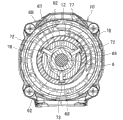
Fig. 3 is A-A line amplification view.
Fig. 4 is B-B line amplification view.
Fig. 5 is C-C line amplification view.
Fig. 6 is D-D line amplification view.
Fig. 7 is E-E line amplification view.
Fig. 8 is F-F line amplification view.
Fig. 9 is G-G line amplification view.
Figure 10 is the longitudinal sectional view (vibrations electric drill pattern) of vibrations bottle opener electric drill.
Figure 11 is H-H line amplification view.
Figure 12 is I-I line amplification view.
Figure 13 is J-J line amplification view.
Figure 14 is K-K line amplification view.
Figure 15 is L-L line amplification view.
Symbol description:
1... shake bottle opener electric drill; 2... body shell; 3... motor; 4... output shaft; 5... gear assembly; 6... main shaft; 7... drill chuck; 8... motor bracket; 9... the first gear-box; 10... the second gear-box; 11... large-diameter portion; 12... minor diameter part; 20... planetary gear reducing mechanism; 23A~23C... internal gear; 24... board; 26... teat; 28... pin; 29... chamfered section; 30... flange part; 34... coupling collar; 50... percussion mechanism; 57... the first cam; 58... the second cam; 67... slip ring; 71... slotted hole; 72... contact pin; 74... helical spring; 76... cam is switched in vibrations; 78... engaging recessed part; 79... pattern is switched ring; 80... operating portion; 85... connecting rod; 90... clutch mechanism; 91... clutch ring; 97... helical spring; 99... engagement pin; 105... keep groove; 106... rubber pin.
Detailed description of the invention
Below, based on accompanying drawing, embodiments of the present invention are described.
Fig. 1 is the longitudinal sectional view representing as the vibrations bottle opener electric drill of an example of electric tool, and Fig. 2 is its exploded perspective view, and the rear portion of vibrations bottle opener electric drill 1 in body shell 2 (is made as front by the right side of Fig. 1.Thereby) storage motor 3 there is the gear assembly 5 of forwards outstanding main shaft 6 transmits rotation from the output shaft 4 of motor 3 to main shaft 6 in the front assembling of this motor 3, be provided with the drill chuck 7 that can control with front end drill bit at the front end of main shaft 6.
Be assembled with the motor bracket 8 of axle supporting output shaft 4 in the front of motor 3, gear assembly 5 is formed by the first gear-box 9 and second gear-box 10 of tubular, wherein the first gear-box 9 links with motor bracket 8, and the second gear-box 10 is assembled in the front of this first gear-box 9 and has two sections of barrel shape of large-diameter portion 11 and minor diameter part 12.Utilize screw 14,14... by 4 boss 13 of the outstanding anterior outer peripheral face that is arranged at the first gear- box 9,13... spinning after the second gear-box 10, thereby this first, second gear- box 9,10 is mutually combined.Utilize screw 15a, 15a... diagrams such as () Fig. 5, Fig. 6 by 4 boss 15 of the rear end outer peripheral face of the outstanding large-diameter portion 11 that is arranged at the second gear- box 10,15... spinning in the front end of body shell 2, thereby by gear assembly 5 and body shell 2 combinations.
At the inside of gear assembly 5 storage planetary gear reducing mechanism 20, this planetary gear reducing mechanism 20 forms by pinion frame 21A, 21B, 21C are configured to three grades vertically, this pinion frame 21A, 21B, 21C support the multiple planetary gears 22, the 22... that revolve round the sun in internal gear 23A, 23B, 23C, and the output shaft 4 of motor 3 engages with the planetary gear 22 of the first order.
Herein, be formed with a pair of board 24,24 at the upper-lower position of motor bracket 8, this a pair of board 24,24 is forwards given prominence to and is arranged with predetermined distance respectively on left and right directions, and runs through and be provided with left and right through hole opposite each other 25 on this pair of board 24,24.On the other hand, at the upper-lower position of the rear end outer peripheral face of the first gear-box 9, be tangentially outstandingly provided with teat 26,26, the left and right width of this teat 26,26 is consistent with the interval of board 24,24, and is formed with through hole 27 at left and right directions.Also as shown in Figure 3, upper and lower teat 26,26 is embedded in respectively under the state of 24,24 of upper and lower boards, make the pair of pin 28,28 that is disposed at the point symmetry position centered by output shaft 4 connect through hole 25 and through hole 27 from left and right directions respectively, thereby motor bracket 8 and the first gear-box 9 are linked mutually.
And, be positioned at motor bracket 8 front surface first order internal gear 23A be formed with up and down the upper and lower a pair of chamfered section 29,29 consistent with the interval of pin 28 and orthogonal and to radially outstanding flange part 30,30 at its rear and chamfered section 29.Under the connecting state of motor bracket 8 and the first gear-box 9, upper and lower pin 28,28 connects the first gear-box 9 in the front of flange part 30,30 along chamfered section 29,29.Thereby internal gear 23A is because chimeric between pin 28 and chamfered section 29 is limited rotation, and be positioned at fore-and-aft direction with flange part 30 by pin 28.The 31st, the packing ring between motor bracket 8 and internal gear 23A.
In addition, in planetary gear reducing mechanism 20, the internal gear 23B of the second level can rotate and can move forward and backward vertically.At the outer peripheral face of this internal gear 23B and at first half, along circumferentially giving prominence to and be provided with multiple axial external tooth 32,32... with predetermined distance, be circumferentially formed with engagement groove 33 on latter half edge.Front portion in the first gear-box 9 maintains coupling collar 34, and this coupling collar 34 is provided with and axial internal tooth 35, the 35... of the external tooth equal number of internal gear 23B inner peripheral surface is outstanding.Chimeric by making at periphery limiting groove 37, the 37... that equally spaced outstanding circumferential ridge 36,36... and the front end inner peripheral surface at the first gear-box 9 arranging is arranged with vertically of coupling collar 34, limit this coupling collar 34 and rotate.
On the other hand, at the outer peripheral face of internal gear 23B and at latter half, speed switching ring 38 is installed.By being located at the chimeric of guiding groove 40 that projection 39,39... and the rear portion inner peripheral surface at the first gear-box 9 of outer peripheral face form vertically, 40..., make speed switch ring 38 and only can move forward and backward, and make the radially engagement groove 33 of the front end insertion internal gear 23B of the combination pin 41 of plug-in mounting of outside from each projection 39.The projection 39 that is positioned at top has rearward outstanding very long extended portion 42, on the rear end of this extended portion 42, the outstanding link sheet 43 arranging links with speed changer lever 44 via the helical spring 45,45 of front and back, this speed changer lever 44 with can before and after the mode of sliding be arranged at body shell 2.
Thereby, if speed changer lever 44 is rearward slided, speed is switched ring 38 via linking sheet 43 and retreating, and internal gear 23B also engages with the engaging tooth 46 of periphery of the pinion frame 21A that is located at the first order with the state engaging of the planetary gear 22 of the second level is constant via keeping in conjunction with pin 41.Thereby, become the fast mode of deceleration of removing the second level.On the contrary, if speed changer lever 44 is forwards slided, internal gear 23B also leaves and advances from pinion frame 21A together with speed switching ring 38, and maintenance is constant with the engagement of the planetary gear 22 of the second level, and external tooth 32 is engaged with the internal tooth 35 of coupling collar 34.Thereby, become the low-speed mode of deceleration of the performance second level.
And, now, in the inner side of the minor diameter part 12 of the second gear-box 10, percussion mechanism 50 is set, this percussion mechanism 50 is given axial vibrations to main shaft 6, at the arranged outside clutch mechanism 90 of minor diameter part 12, this clutch mechanism 90 cuts off the transmission of torque to main shaft 6 with the load of the regulation of giving main shaft 6, by handover operation described later, can select respectively following pattern: the vibrations electric drill pattern of main shaft 6 rotation limits, limit vibrations; The electric drill pattern that main shaft 6 is only rotated; Cut off the clutch mode (playing subpattern) of the transmission of torque to main shaft 6 with the load of regulation.Below, each mechanism is described.
First, in percussion mechanism 50, main shaft 6 supports at interior ball bearing 16,17 axles by front and back of minor diameter part 12, and its rear end is incorporated into and the locking cam 51 of the pinion frame 21C one of the third level by spline, and can move forward and backward vertically.The 52nd, the lid covering from the front of locking cam 51 in minor diameter part 12.
Wherein, utilize and be formed near the helical spring 54 of installing between the flange 53 in the front of main shaft 6 and ball bearing 17, under normal conditions, to main shaft 6 towards the back-up ring 55 that the rear position of ball bearing 17 is installed and the progressive position application of force of ball bearing 17 butts.The 56th, before embedding minor diameter part 12, bring in the distance piece that ball bearing 17 is positioned.
And, between the ball bearing 16,17 of main shaft 6, start to be provided with coaxially respectively the first cam 57, second cam 58 of ring-type from front.The first cam 57 is formed with radially along circumferential continuous the first cam tooth 59,59... after it, and is fixedly installed in main shaft 6.The second cam 58 with the opposed front surface of the first cam tooth 59 be formed with same shape the second cam tooth 60,60... matched in clearance insert main shaft 6, in front end periphery, be arranged with flange 61, and, also as shown in Figure 7, at its rear, outstanding being provided with along equally spaced 3 engagement projections 62 of circumferentially spaced, 62....
And, give prominence in the front of the second cam 58 and at the inner peripheral surface of minor diameter part 12 the rank portion 63 that is provided with ring-type, at the rear of the second cam 58, also maintain packing ring 66 at the front surface that is fixed on the baffle plate 64 in minor diameter part 12 via multiple steel balls 65,65... as illustrated in fig. 6.Thereby the second cam 58 has been limited axial movement between rank portion 63 and packing ring 66.
On the other hand, in minor diameter part 12 and in the outside of the second cam 58, be accommodated with the slip ring 67 with the second cam 58 roughly the same diameters.Also as shown in Figure 6,7, along circumferentially spaced equally spaced 3 restrictions projections 68,68..., to be integrally formed at this slip ring 67 to the inside and outside outstanding mode of ring diametrically, and the outstanding part laterally that respectively limits projection 68 is chimeric with the axial guiding groove 69 of inner surface that is formed at minor diameter part 12 respectively.Thus, the state that slip ring 67 can be limited to rotate can move forward and backward in minor diameter part 12.Radially run through respectively and be provided with connect apertures 70 in each restriction projection 68, outstanding part is formed as more tending to central side and the circumferential less cone-shaped of thickness to the inside.Form cam mechanism by this slip ring 67 with first, second cam 57,58.
In addition, in minor diameter part 12, running through respectively for restriction projection 68 chimeric each guiding groove 69 slotted hole 71 extending before and after being provided with, being inserted in the connect apertures 70 of restriction projection 68 at the inner end of the contact pin 72 that radially connects each slotted hole 71 of minor diameter part 12.In the periphery of minor diameter part 12 and from the rear of the outstanding contact pin 72 of slotted hole 71, packing ring 73 is being installed, and, at its rear and at the root of minor diameter part 12, helical spring 74 is installed.Thereby, because the active force of helical spring 74 puts on contact pin 72 via packing ring 73, thereby forwards to contacting pin 72 and slip ring 67 application of forces with its link.
Wherein, contacting the outside of selling 72 and the vibrations switching cam 76 that tubular is rotatably installed at minor diameter part 12, these vibrations are switched cam 76 and have been limited movement forwards by back-up ring 75, and contact is sold 72 outer end and is limited movement forwards shaking cam ridge 77 butts that enclose on week in the front end that switches cam 76.At the end edge of this cam ridge 77 and on three positions that circumferentially uniformly-spaced separate, be also formed with as illustrated in fig. 9 engaging recessed part 78, the 78... of trapezoidal shape.
Thereby, if make vibrations switch cam 76 to engaging recessed part 78 with contact pin 72 and become the first position of rotation rotation of identical phase place, contact sells 72 becomes the progressive position engaging with engaging recessed part 78.On the other hand, if make vibrations switch cam 76 to engaging recessed part 78 with contact phase place that pin 72 staggers, the second position of rotation rotation, contact pin 72 become from engaging recessed part 78 depart from and to the end edge of cam ridge 77 and then the going-back position of engagement.At the progressive position of contact pin 72, slip ring 67 also can before so that with flange 61 butts of the second cam 58, make to limit projection 68 between the engagement projections 62 of the second cam 58 and the rotation (the first sliding position) of restriction the second cam 58.On the other hand, at the going-back position of contact pin 72, slip ring 67 also retreats and makes to limit projection 68 and back out between engagement projections 62, thereby makes freely (second sliding position) of rotation of the second cam 58.
The rotation that cam 76 is switched in this vibrations is switched ring 79 and is carried out by being rotatably mounted in the pattern of large-diameter portion 11 of the second gear-box 10.This pattern is switched ring 79 and is formed as having forwardly and the operating portion 80 of large-diameter portion 11 roughly the same diameters, in having in the wings, insert in the secondary diameter of the interior interpolating unit 81 of the path of large-diameter portion 11, in the periphery of interior interpolating unit 81, to be formed with vertically three embeded slots 82,82... in the equally spaced mode of circumferentially spaced.Equally, be formed with three otch 83,83... in the phase place identical with embeded slot 82 and in the rear end of vibrations switching cam 76.
On the other hand, the front surface of the closure 18 coupling together between by the large-diameter portion of the second gear-box 10 11 and minor diameter part 12, as shown in Figure 5, be concaved with and circumferentially there is three housing recess 84, the 84... of specific length, and in each housing recess 84, there is the connecting rod 85 of two ends towards " コ " in front shape along the radial arrangement of closure 18, make the end 86 in outside be embedded in the embeded slot 82 of interior interpolating unit 81, on the other hand, make the end 87 of inner side be limited to the otch 83 of vibrations switching cam 76.Thereby, make pattern switch ring 79 rotations if control operating portion 80, cam 76 rotation simultaneously via connecting rod 85 is switched in the vibrations of inner side, thereby can make contact pin 72 and slip ring 67 move forward and backward.
Next, clutch mechanism 90 is described.
First, switch the front of ring 79 and at minor diameter part 12, the clutch ring 91 that is formed with internal thread part 92 interior week is rotatably installed in pattern, and, side therein, is provided with periphery and is formed with the spring base 93 of external thread part 94 with the state screwing with clutch ring 91.The projection 95 of this spring base 93 by making to be formed at interior week is chimeric with the axial groove 96 of periphery that is formed at minor diameter part 12, and can move forward and backward vertically with the state that has been limited rotation.In addition, internal diameter is installed than the large helical spring 97 of vibrations switching cam 76 at the rear of spring base 93 and at minor diameter part 12, the front end of helical spring 97 is held in spring base 93, on the other hand, and the rear end of helical spring 97 and packing ring 98 butts of front surface of being located at closure 18.This packing ring 98 is with the state and the front surface butt of closure 18 of 86,87 of the inside and outside ends by connecting rod 85, thus not with the mobile interference of connecting rod 85 of switching the rotation of ring 79 along with pattern.
And six roots of sensation engagement pin 99,99... equally spaced and in the mode that can move forward and backward connect closure 18 at circumferentially spaced, and make front end and packing ring 98 butts, on the other hand, make the front surface butt of the internal gear 23C of rear end and the third level.The cam projection 100 of the trapezoidal shape between engagement pin 99,100... circumferentially equally spaced with the front surface butt of internal gear 23C.
Thereby engagement pin 99 is pushed on the front surface of internal gear 23C by the active force of the helical spring 97 that transmits via packing ring 98, thereby and is circumferentially engaging the rotation of internal gear 23C is limited with cam projection 100.If rotation operated clutch ring 91, spring base 93 screw thread feeding vertically, and make helical spring 97 stretch vertically to adjust pressing force.In the front side of clutch ring 91 and at minor diameter part 12, utilize back-up ring 101 to fix buckle (click) plate 102, engage, separate the snap effect can obtain rotating operated clutch ring 91 time with multiple recesses 104, the 104... of the front surface that is formed at clutch ring 91 by the buckling piece 103 that makes buckle (click) plate 102.
On the other hand, at the front end inner peripheral surface except limiting groove 37 of the first gear-box 9, also as shown in Figure 4, start to be formed with axial maintenance groove 105,105... in the mode along circumferentially spaced predetermined distance from front end, and maintain rubber pin 106 at each maintenance groove 105.This rubber pin 106 is positioned at the outer peripheral face of coupling collar 34 of its inner side and mode and their butts of the outer peripheral face of internal gear 23C to cross over, and is compressed between the first gear-box 9 and coupling collar 34 and internal gear 23C.Thus, under internal gear 23C normality, be subject to the resistance of direction of rotation because of rubber pin 106.
And, between the housing recess 84 of closure 18, also as illustrated in fig. 8 from front matched in clearance be inserted with banking pin 107.This banking pin 107 be front end have large footpath head 108, make the pin that rear end is outstanding to the rear of closure 18 and engage with the external tooth 32 of internal gear 23C, and by between closure 18 and head 108, be installed on banking pin 107 helical spring 109 and by the application of force forwards.Pattern switch ring 79 interior interpolating unit 81 be positioned at banking pin 107 front and with head 108 butts, at the end edge of interior interpolating unit 81, be formed with otch 110, the 110... of the trapezoidal shape corresponding with the phase place of banking pin 107.; if switch the rotation operation of ring 79 by pattern; make otch 110 consistent with the phase place of banking pin 107; before banking pin 107 and then from the external tooth 32 of internal gear 23C, leave until head 108 is chimeric with otch 110; operate if switch the rotation of ring 79 by pattern the phase shifting that makes otch 110 and banking pin 107; banking pin 107 retreats to the end edge of interior interpolating unit 81 by leaving from otch 110, thereby engages with external tooth 32.Utilize this engaging, lock the rotation of internal gear 23C.
As described below, shaking as constructed as above in bottle opener electric drill 1, switch the rotation operation of ring 79 by pattern, can select three patterns.
First, become first switching position (connecting rod 85 is arranged in the position of Fig. 5 double dot dash line represented (A)) of the phase place identical with banking pin 107 at the otch 110 of pattern switching ring 79, as mentioned above, before banking pin 107 and then remove the spin locking of internal gear 23C.Now, pattern is switched ring 79 and is made vibrations switch cam 76 to engaging recessed part 78 and the second position of rotation rotation that contacts pin 72 and stagger via connecting rod 85.Thereby, the second cam 60 becomes free rotation state, internal gear 23C becomes the state that is limited rotation due to the pressing force of helical spring 97, and reach clutch mode, under this clutch mode, by the rotation operation of clutch ring 91, can change the pressing force (torque capacity) that engagement pin 99 is applied.
Under this clutch mode, if motor 3 is driven, main shaft 6 is rotated, can utilize the screwdriver head that is installed on drill chuck 7 to carry out screw fastening etc.Here, owing to by rubber pin 106, internal gear 23C being given the resistance of direction of rotation, thus in the case of the pressing force of helical spring 97 set is little, even moment apply the starting torque of motor 3, also can suppress the idle running of internal gear 23C, can not produce the early cut-off of clutch.
Load main shaft 6 being applied if screw fastening is proceeded exceedes the pressing force of the helical spring 97 of fixed annulus 23C, forwards pushing out card dowel pin 99 and relatively make it to cross cam projection 100 of the cam projection 100 of internal gear 23C, thus make internal gear 23C idle running and make screw fastening finish (clutch work).Now, even if there is the resistance being caused by rubber pin 106, internal gear 23C also can dally.In addition, even there is because of screwdriver head, thereby screw pushing retreating main shaft 6 to cause the situation of the first cam 57 and the second cam 58 butts, because the second cam 58 is in free rotation state, so can rotate together with the first cam 57.Thereby, on main shaft 6, can not produce vibrations.
Next, start postrotational the second switching position left (connecting rod 85 is the position of solid line Fig. 5 represented (B)) from clutch mode making pattern switch ring 79 from forward observation, otch 110 becomes the phase place staggering with banking pin 107 as illustrated in fig. 8, therefore on banking pin 107, retreat to the end edge of interior interpolating unit 81, and then the rotation of locking internal gear 23C.On the other hand, now, vibrations are switched cam 76 and are also positioned at as illustrated in fig. 9 engaging recessed part 78 and contact the second position of rotation that pin 72 staggers, and therefore, the second cam 58 keeps free state constant.Thereby, become electric drill pattern, no matter the size of the pressing force of helical spring 97 is how, always the rotation of internal gear 23C is locked.
If main shaft 6 is rotated under this electric drill pattern, no matter load that main shaft 6 is applied how, main shaft 6 can continue rotation.Certainly, on main shaft 6, can not produce vibrations.
And, start further left postrotational the 3rd switching position (connecting rod 85 is the represented position of (C) and the solid line position of Figure 11 of double dot dash line Fig. 5) from electric drill pattern making pattern switch ring 79, as shown in figure 14, otch 110 only further leaves from banking pin 107, the state of phase shifting does not change, so the rotation of internal gear 23C is locked.On the other hand, vibrations are switched cam 76 and are arrived engaging recessed part 78 and contact pin 72 and become the first position of rotation of identical phase place, therefore, as shown in Figure 12 and Figure 15, contact pin 72 active forces because of helical spring 74 engage with engaging recessed part 78, as shown in Figure 10 and Figure 12,13, slip ring 67 advances, thus the rotation of restriction the second cam 58.Thereby, become the vibrations electric drill pattern at going-back position the first cam 57 and second cam 58 butts of main shaft 6.
Under this vibrations electric drill pattern, if drill bit etc. is pressed on to processed material so that the state that main shaft 6 retreats make it rotation, interfere with the first cam tooth 59 of the first cam 57 and second cam tooth 60 of confined the second cam 58 of rotation of main shaft 6 one rotations, thereby produce axial vibrations on main shaft 6.In addition, because the rotation of internal gear 23C is locked, so though the load that main shaft 6 is applied how, main shaft 6 all continues rotation.
In addition, in the periphery of the large-diameter portion 11 of the second gear-box 10, show as illustrated in fig. 2 to have the selected marker 111 of each pattern, switch on ring 79 in pattern, be marked with mark 112, the 112... of three that represent each pattern.Thereby, by making mark 112 and mark 111 obtain desirable pattern to incompatible.
Like this, according to the vibrations bottle opener electric drill 1 of aforesaid way, the pair of pin 28,28 connecting by leap motor bracket 8 and the first gear-box 9 is carried out the combination of motor bracket 8 and the first gear-box 9, and, make pin 28,28 engage and limit the rotation of internal gear 23A and carry out axial location with the internal gear 23A of the first order of planetary gear reducing mechanism 20, thereby can make the combination of motor bracket 8 and the first gear-box 9 and the assembling of internal gear 23A carry out jointly mutually.Thereby, the shape of the first gear-box 9 can be simplified and rigidity can be guaranteed.
, on pin 28 point symmetry positions centered by the output shaft 4 by motor 3, be set to a pair ofly especially here, therefore, can make motor bracket 8 and the first gear-box 9 become one more reliably.
In addition, in the side of internal gear 23A, form the chamfered section 29,29 along pin 28,28, at the rear of chamfered section 29,29, form with chamfered section 29 orthogonal and to the radially outstanding flange part 30,30 of internal gear 23A, butt by pin 28 with chamfered section 29, limit the rotation of internal gear 23A, and by the butt of pin 28 and flange part 30, carry out the axial location of internal gear 23A, thereby the rotation that utilizes a pin 28 can carry out internal gear 23A limits the rational formation with axial location simultaneously.
In addition, in aforesaid way, make pin connect to realize the combination of motor bracket and gear-box at left and right directions, but also can make it above-below direction connect combination.In addition, in aforesaid way, make the teat of gear-box between the board of being located at motor bracket, make pin connect, but also can in contrast, in motor bracket, teat be set, at gear-box, board is set, be also do not have influential.Certainly, the shape of board, teat can suitably change, if in conjunction with time obtain integraty, only have so a pin to be also fine.
And the shape of motor bracket, gear-box itself is also not limited to aforesaid way.For example gear-box can not be also that two of aforesaid way and so on is cut apart structure, but both are integrally formed.
On the other hand, pin can replace chamfered section with groove with engaging of internal gear, or replaces chamfered section, flange part and pin is connected to internal gear etc. along the tangential direction of internal gear, if can be rotated restriction and positioning instant can, be not limited to aforesaid way.
And, be not limited to vibrations bottle opener electric drill as electric tool, as long as possessing the electric tool of structure of motor and the gear-box combination via motor bracket, electric screw driver, electric drill, other the type such as impact driver all can adopt the present invention.
Claims (3)
1. an electric tool, dispose the gear-box of the tubular of having received planetary gear reducing mechanism in the front of motor, and described motor and described gear-box are via being installed on the motor bracket of tubular of described motor and combination, and this electric tool is characterised in that
Utilize to connect at least one pin of described motor bracket and described gear-box across the mode of described motor bracket and described gear-box, carry out the combination of described motor bracket and described gear-box, and, described pin is engaged with the internal gear of the first order of described planetary gear reducing mechanism, limit the rotation of described internal gear and carry out axial location.
2. electric tool according to claim 1, is characterized in that,
Point symmetry position centered by the output shaft by described motor arranges a pair of described pin.
3. according to the electric tool described in claim 1 or 2, it is characterized in that,
Side at described internal gear forms the chamfered section along described pin, form orthogonal with described chamfered section and along the radially outstanding flange part of described internal gear at the rear of described chamfered section, utilize the butt of described pin and described chamfered section to limit the rotation of described internal gear, and utilize the butt of described pin and described flange part to carry out the axial location of described internal gear.
Applications Claiming Priority (2)
| Application Number | Priority Date | Filing Date | Title |
|---|---|---|---|
| JP2011-083935 | 2011-04-05 | ||
| JP2011083935A JP5649500B2 (en) | 2011-04-05 | 2011-04-05 | Electric tool |
Publications (2)
| Publication Number | Publication Date |
|---|---|
| CN102729222A CN102729222A (en) | 2012-10-17 |
| CN102729222B true CN102729222B (en) | 2014-06-04 |
Family
ID=45808222
Family Applications (1)
| Application Number | Title | Priority Date | Filing Date |
|---|---|---|---|
| CN201210094049.9A Active CN102729222B (en) | 2011-04-05 | 2012-03-31 | Power tool |
Country Status (5)
| Country | Link |
|---|---|
| US (1) | US8684882B2 (en) |
| EP (1) | EP2508302B1 (en) |
| JP (1) | JP5649500B2 (en) |
| CN (1) | CN102729222B (en) |
| RU (1) | RU2601529C2 (en) |
Families Citing this family (15)
| Publication number | Priority date | Publication date | Assignee | Title |
|---|---|---|---|---|
| DE102008041599A1 (en) | 2008-08-27 | 2010-03-04 | Robert Bosch Gmbh | Switchable transmission in a hand tool |
| JP2012218089A (en) * | 2011-04-05 | 2012-11-12 | Makita Corp | Power tool |
| JP5628079B2 (en) * | 2011-04-05 | 2014-11-19 | 株式会社マキタ | Vibration driver drill |
| JP5938652B2 (en) * | 2012-05-10 | 2016-06-22 | パナソニックIpマネジメント株式会社 | Electric tool |
| JP6013929B2 (en) * | 2013-01-22 | 2016-10-25 | 株式会社マキタ | Electric tool |
| US10040178B2 (en) | 2014-05-27 | 2018-08-07 | Makita Corporation | Power tool and rotary impact tool |
| JP6491904B2 (en) * | 2015-02-19 | 2019-03-27 | 株式会社マキタ | Electric tool |
| WO2018039343A1 (en) * | 2016-08-24 | 2018-03-01 | Cts Corporation | Modular vehicle engine component actuator |
| JP7049929B2 (en) | 2018-06-06 | 2022-04-07 | 株式会社マキタ | Power tools and electric vibration driver drills |
| US11267118B2 (en) | 2018-11-08 | 2022-03-08 | Makita Corporation | Electric power tool |
| JP7182998B2 (en) * | 2018-11-08 | 2022-12-05 | 株式会社マキタ | Electric tool |
| US11453109B2 (en) * | 2019-01-09 | 2022-09-27 | Makita Corporation | Power tool |
| JP7382197B2 (en) | 2019-01-09 | 2023-11-16 | 株式会社マキタ | Electric tool |
| JP7263155B2 (en) * | 2019-06-28 | 2023-04-24 | 株式会社マキタ | Electric tool |
| EP4059665A1 (en) * | 2020-12-21 | 2022-09-21 | Techtronic Cordless GP | Power tool with gear assembly |
Citations (4)
| Publication number | Priority date | Publication date | Assignee | Title |
|---|---|---|---|---|
| DE10149382C1 (en) * | 2001-10-06 | 2003-05-08 | Bosch Gmbh Robert | Device for switching a two-stage transmission of a power tool |
| CN1643270A (en) * | 2002-01-25 | 2005-07-20 | 布莱克-德克尔公司 | Power drill/driver |
| EP1574294B1 (en) * | 2004-03-10 | 2010-07-07 | Makita Corporation | Impact driver |
| CN201769185U (en) * | 2010-08-18 | 2011-03-23 | 宁波新港工具有限公司 | Gear box for electric tool |
Family Cites Families (13)
| Publication number | Priority date | Publication date | Assignee | Title |
|---|---|---|---|---|
| SU1009748A1 (en) * | 1981-02-03 | 1983-04-07 | Предприятие П/Я А-7332 | Portable nut or screw driver |
| SU965754A1 (en) * | 1981-03-26 | 1982-10-15 | Предприятие П/Я Р-6271 | Apparatus for unscrewing and screwing-on nuts on motor rotor shaft |
| JPS5953164A (en) * | 1982-09-20 | 1984-03-27 | 松下電工株式会社 | Electric driver |
| JPS62166971A (en) * | 1986-01-20 | 1987-07-23 | 松下電工株式会社 | Electric driver |
| SE503889C2 (en) * | 1994-10-31 | 1996-09-23 | Atlas Copco Tools Ab | Reversible nut wrench |
| JPH10329056A (en) * | 1997-05-27 | 1998-12-15 | Matsushita Electric Works Ltd | Power tool |
| JP2000320438A (en) * | 1999-05-12 | 2000-11-21 | Mitsubishi Electric Corp | Starter motor |
| US6676557B2 (en) * | 2001-01-23 | 2004-01-13 | Black & Decker Inc. | First stage clutch |
| US7066691B2 (en) | 2002-01-25 | 2006-06-27 | Black & Decker Inc. | Power drill/driver |
| JP4084319B2 (en) * | 2004-02-23 | 2008-04-30 | リョービ株式会社 | Electric tool |
| EP1970165A1 (en) * | 2007-03-12 | 2008-09-17 | Robert Bosch Gmbh | A rotary power tool operable in a first speed mode and a second speed mode |
| DE102009013108A1 (en) * | 2009-03-13 | 2010-09-16 | Metabowerke Gmbh | Electric motor driven screwing or drilling tool |
| CN102148548B (en) * | 2010-02-09 | 2015-05-06 | 德昌电机(深圳)有限公司 | Motor component used for medical appliance |
-
2011
- 2011-04-05 JP JP2011083935A patent/JP5649500B2/en active Active
-
2012
- 2012-03-01 US US13/409,761 patent/US8684882B2/en active Active
- 2012-03-01 EP EP12157743.1A patent/EP2508302B1/en active Active
- 2012-03-31 CN CN201210094049.9A patent/CN102729222B/en active Active
- 2012-04-04 RU RU2012113211/02A patent/RU2601529C2/en active
Patent Citations (4)
| Publication number | Priority date | Publication date | Assignee | Title |
|---|---|---|---|---|
| DE10149382C1 (en) * | 2001-10-06 | 2003-05-08 | Bosch Gmbh Robert | Device for switching a two-stage transmission of a power tool |
| CN1643270A (en) * | 2002-01-25 | 2005-07-20 | 布莱克-德克尔公司 | Power drill/driver |
| EP1574294B1 (en) * | 2004-03-10 | 2010-07-07 | Makita Corporation | Impact driver |
| CN201769185U (en) * | 2010-08-18 | 2011-03-23 | 宁波新港工具有限公司 | Gear box for electric tool |
Non-Patent Citations (1)
| Title |
|---|
| JP特开平10-329056A 1998.12.15 |
Also Published As
| Publication number | Publication date |
|---|---|
| RU2012113211A (en) | 2013-10-10 |
| US8684882B2 (en) | 2014-04-01 |
| EP2508302B1 (en) | 2014-01-22 |
| JP2012218088A (en) | 2012-11-12 |
| RU2601529C2 (en) | 2016-11-10 |
| JP5649500B2 (en) | 2015-01-07 |
| US20120258832A1 (en) | 2012-10-11 |
| CN102729222A (en) | 2012-10-17 |
| EP2508302A1 (en) | 2012-10-10 |
Similar Documents
| Publication | Publication Date | Title |
|---|---|---|
| CN102729222B (en) | Power tool | |
| CN102729221A (en) | Percussion driver drill | |
| CN100409984C (en) | Percussion drill | |
| CN102909681B (en) | Electric power tool | |
| CN100354074C (en) | Electric power tool | |
| EP1946895B1 (en) | Power tool | |
| CN102825583B (en) | Impact tool | |
| CN100500351C (en) | Multifunction drill | |
| CN101530991B (en) | Impact tool | |
| CN102310380B (en) | Impact tool | |
| CN104339324A (en) | Impact tool | |
| CN101143440A (en) | Electric power tool | |
| CN102829161A (en) | Electric power tool | |
| CN102909682A (en) | Electric power tool with vibration mechanism | |
| CN104646724A (en) | Multi-speed cycloidal transmission | |
| CN102729189A (en) | Power tool | |
| CN102294681B (en) | Impact tool | |
| CN103291909B (en) | Anti-misconnection protection device for automotive transmission | |
| CN202895104U (en) | Tool rotation connection rod | |
| CN210537395U (en) | Insert and plant clutch, insert and plant transmission and paddy field operation machine | |
| CN102601420A (en) | Electric tool with rotary impact function | |
| CN217993957U (en) | Pencil feeding mechanism of pencil sharpener | |
| CN202572340U (en) | Electric tool with rotating impact function | |
| CN217713524U (en) | Multi-gear power output system | |
| CN216478864U (en) | Parking and gear shifting mechanism, speed change system and vehicle |
Legal Events
| Date | Code | Title | Description |
|---|---|---|---|
| C06 | Publication | ||
| PB01 | Publication | ||
| C10 | Entry into substantive examination | ||
| SE01 | Entry into force of request for substantive examination | ||
| C14 | Grant of patent or utility model | ||
| GR01 | Patent grant |