JP5583500B2 - Impact tool - Google Patents
Impact tool Download PDFInfo
- Publication number
- JP5583500B2 JP5583500B2 JP2010153271A JP2010153271A JP5583500B2 JP 5583500 B2 JP5583500 B2 JP 5583500B2 JP 2010153271 A JP2010153271 A JP 2010153271A JP 2010153271 A JP2010153271 A JP 2010153271A JP 5583500 B2 JP5583500 B2 JP 5583500B2
- Authority
- JP
- Japan
- Prior art keywords
- spindle
- washer
- hammer
- locking
- housing
- Prior art date
- Legal status (The legal status is an assumption and is not a legal conclusion. Google has not performed a legal analysis and makes no representation as to the accuracy of the status listed.)
- Active
Links
Images


Classifications
-
- B—PERFORMING OPERATIONS; TRANSPORTING
- B25—HAND TOOLS; PORTABLE POWER-DRIVEN TOOLS; MANIPULATORS
- B25B—TOOLS OR BENCH DEVICES NOT OTHERWISE PROVIDED FOR, FOR FASTENING, CONNECTING, DISENGAGING OR HOLDING
- B25B21/00—Portable power-driven screw or nut setting or loosening tools; Attachments for drilling apparatus serving the same purpose
- B25B21/02—Portable power-driven screw or nut setting or loosening tools; Attachments for drilling apparatus serving the same purpose with means for imparting impact to screwdriver blade or nut socket
- B25B21/026—Impact clutches
-
- B—PERFORMING OPERATIONS; TRANSPORTING
- B25—HAND TOOLS; PORTABLE POWER-DRIVEN TOOLS; MANIPULATORS
- B25B—TOOLS OR BENCH DEVICES NOT OTHERWISE PROVIDED FOR, FOR FASTENING, CONNECTING, DISENGAGING OR HOLDING
- B25B21/00—Portable power-driven screw or nut setting or loosening tools; Attachments for drilling apparatus serving the same purpose
- B25B21/02—Portable power-driven screw or nut setting or loosening tools; Attachments for drilling apparatus serving the same purpose with means for imparting impact to screwdriver blade or nut socket
- B25B21/023—Portable power-driven screw or nut setting or loosening tools; Attachments for drilling apparatus serving the same purpose with means for imparting impact to screwdriver blade or nut socket for imparting an axial impact, e.g. for self-tapping screws
Description
本発明は、ハウジングの前方へ突出させたアンビルに回転打撃力を発生させるインパクトドライバ等の打撃工具に関する。 The present invention relates to an impact tool such as an impact driver that generates a rotational impact force on an anvil protruding forward of a housing.
インパクトドライバ等の打撃工具においては、ハウジング内でモータによって回転するスピンドルと、そのスピンドルの前方でハウジングに同軸で軸支され、ビットが装着される前端をハウジングの前方へ突出させたアンビルと、スピンドルの回転を回転打撃力としてアンビルに伝達する打撃機構とを備えたものが知られている(特許文献1参照)。
この打撃機構は、スピンドルへ前後移動可能に外装されるハンマーを備え、スピンドルとハンマーとのカム溝間に跨ってボールを嵌合させると共に、ハンマーの後面に形成したリング溝に前端が挿入されるコイルバネによってハンマーをアンビルと係合する前進位置に付勢することで構成されている。よって、ネジ締め等によってスピンドルが回転すると、ハンマーもボールを介して一体回転し、アンビルを回転させるが、アンビルへの負荷が高まると、ボールがカム溝に沿って後方へ転動することでハンマーがコイルバネの付勢に抗して後退する。そして、アンビルとの係合が解かれると、再びコイルバネの付勢により、ボールがカム溝に沿って前方へ転動することでハンマーが回転しながらアンビルに再係合する。このアンビルに対する係脱をハンマーが繰り返すことで間欠的な回転打撃力が発生することになる。
In an impact tool such as an impact driver, a spindle that is rotated by a motor in a housing, an anvil that is coaxially supported by the housing in front of the spindle, and has a front end protruding to the front of the housing, and a spindle There is known a striking mechanism that transmits a rotation striking force as a rotational striking force to an anvil (see Patent Document 1).
This striking mechanism includes a hammer that is mounted on the spindle so as to move back and forth, and fits the ball across the cam groove between the spindle and the hammer, and the front end is inserted into a ring groove formed on the rear surface of the hammer. The coil spring is configured to urge the hammer to an advanced position that engages with the anvil. Therefore, when the spindle rotates due to screw tightening or the like, the hammer also rotates integrally with the ball and rotates the anvil. However, when the load on the anvil increases, the ball rolls backward along the cam groove to cause the hammer to rotate. Retreats against the bias of the coil spring. When the engagement with the anvil is released, the ball rolls forward along the cam groove again by the bias of the coil spring, so that the hammer re-engages with the anvil while rotating. The hammer repeatedly repeats engagement / disengagement with respect to the anvil, thereby generating intermittent rotational striking force.
一方、この打撃工具においては、スピンドルの後部に遊星歯車のキャリア部が形成され、そのキャリア部の前方に、ハンマーを付勢するコイルバネの後端を受けるワッシャーが設けられている。このワッシャーは、コイルバネの後端が当接する外周よりも中心側が前方へ膨出してコイルバネに嵌合し、コイルバネの内径の収縮を規制するようになっている。この膨出部はハンマーの後方に位置するため、設計に当たっては、後退するハンマーが膨出部に当接しないようにハンマーのストローク範囲をワッシャーより前寄りに設定する必要があり、ひいては工具全体の軸方向の長さが長くなってしまう。 On the other hand, in this impact tool, a carrier part of the planetary gear is formed at the rear part of the spindle, and a washer for receiving the rear end of the coil spring that urges the hammer is provided in front of the carrier part. The washer is configured such that the center side bulges forward from the outer periphery with which the rear end of the coil spring abuts and is fitted to the coil spring to restrict contraction of the inner diameter of the coil spring. Since this bulge is located behind the hammer, it is necessary to set the stroke range of the hammer closer to the front of the washer so that the retracting hammer does not come into contact with the bulge. The axial length becomes long.
そこで、本発明は、コイルバネの後端を受けるワッシャーと干渉することなくハンマーの後退量を確保でき、軸方向の長さを短くしてコンパクト化を達成することができる打撃工具を提供することを目的としたものである。 Therefore, the present invention provides a striking tool that can ensure the amount of retraction of the hammer without interfering with the washer that receives the rear end of the coil spring, and can achieve compactness by reducing the axial length. It is intended.
上記目的を達成するために、請求項1に記載の発明は、ハウジング内に、モータと、そのモータの駆動で回転するスピンドルと、そのスピンドルの前方で前記ハウジングに同軸で軸支され、前端を前記ハウジングの前方へ突出させたアンビルと、前記スピンドルの回転を回転打撃力として前記アンビルに伝達する打撃機構とを備え、前記打撃機構を、前記スピンドルに外装されて前後移動可能なハンマーと、前記スピンドルとハンマーとにそれぞれ設けたカム溝間に跨って嵌合するボールと、前端が前記ハンマーの後面に形成したリング溝に挿入して前記ハンマーを前進位置に付勢するコイルバネとで形成し、前記スピンドルにおける前記コイルバネの後方に、前記モータの回転を減速する遊星歯車を保持するキャリア部を設けて、前記キャリア部の前方に前記コイルバネの後端を受けるワッシャーを配置した打撃工具であって、前記ワッシャーを、前記リング溝の内径より大きい内径を有して内周縁に前方への立ち上げ部を立設したリング状とすると共に、前記ワッシャーに係止部を設け、前記キャリア部の側面に、前記係止部が係止する被係止部を設けて、前記係止部と前記被係止部との係止によって前記ワッシャーを前記スピンドルとの同軸位置に位置決めすることを特徴とするものである。
請求項2に記載の発明は、請求項1の構成において、前記係止部を、前記ワッシャーの外周部から後方へ向けて折り曲げ形成され、前記ワッシャーの半径方向に弾性を有する複数の係止片とし、前記被係止部を、前記キャリア部の側面に形成された複数の面取部と、その面取部にそれぞれ凹設されて前記係止片が係止する凹部としたことを特徴とするものである。
請求項3に記載の発明は、ハウジング内に、モータと、そのモータの駆動で回転するスピンドルと、そのスピンドルの前方で前記ハウジングに同軸で軸支され、前端を前記ハウジングの前方へ突出させたアンビルと、前記スピンドルの回転を回転打撃力として前記アンビルに伝達する打撃機構とを備え、前記打撃機構を、前記スピンドルに外装されて前後移動可能なハンマーと、前記スピンドルとハンマーとにそれぞれ設けたカム溝間に跨って嵌合するボールと、前端が前記ハンマーの後面に形成したリング溝に挿入して前記ハンマーを前進位置に付勢するコイルバネとで形成し、前記スピンドルにおける前記コイルバネの後方に、前記モータの回転を減速する遊星歯車を保持するキャリア部を設けて、前記キャリア部の前方に前記コイルバネの後端を受けるワッシャーを配置した打撃工具であって、前記ワッシャーを、前記リング溝の内径より大きい内径を有して内周縁に前方への立ち上げ部を立設したリング状とすると共に、前記ワッシャーに係止部を設け、前記キャリア部に、前記係止部が押圧して係止する被係止部を設けて、前記係止部と前記被係止部との係止によって前記ワッシャーを前記スピンドルとの同軸位置に位置決めすることを特徴とするものである。
In order to achieve the above object, an invention according to
According to a second aspect of the present invention, in the configuration of the first aspect, the plurality of locking pieces are formed by bending the locking portion from the outer peripheral portion of the washer toward the rear, and having elasticity in the radial direction of the washer. And the to-be-latched portion is a plurality of chamfered portions formed on the side surface of the carrier portion, and a concave portion that is recessed in each of the chamfered portions and engages with the locking piece. To do.
According to a third aspect of the present invention, a motor, a spindle that is rotated by driving the motor, and a shaft that is coaxially supported by the housing in front of the spindle and having a front end projecting forward of the housing. An anvil and a striking mechanism that transmits the rotation of the spindle to the anvil as a rotational striking force, and the striking mechanism is provided on each of the hammer that is mounted on the spindle and is movable back and forth, and the spindle and the hammer. A ball that fits between the cam grooves and a coil spring whose front end is inserted into a ring groove formed on the rear surface of the hammer and urges the hammer to the forward position are formed behind the coil spring in the spindle. A carrier portion for holding a planetary gear that decelerates rotation of the motor is provided, and the coil bar is disposed in front of the carrier portion. The rear end impact tool placing the washer undergoing, the washer, with a ring-shaped erected the rising portion of the forward inner edge having an inner diameter larger than an inner diameter of the ring groove, The washer is provided with a locking portion, the carrier portion is provided with a locked portion that is pressed and locked by the locking portion, and the washer is locked by the locking portion and the locked portion. Is positioned at a position coaxial with the spindle .
本発明によれば、コイルバネの後端を受けるワッシャーと干渉することなくハンマーの後退量を確保できる。よって、軸方向の長さを短くすることができ、コンパクト化が達成可能となる。而も、コイルバネの内側のスペースを有効利用してハンマーの後退量を確保しているので、ワッシャーが径方向等に大きくなることがなく、コンパクト化の妨げにならない。
また、ワッシャーの係止部とキャリア部の被係止部との係止により、ワッシャーを位置ずれなく確実に位置決め可能となる。
According to the present invention, the amount of retraction of the hammer can be ensured without interfering with the washer that receives the rear end of the coil spring. Therefore, the axial length can be shortened, and compactness can be achieved. In addition, since the amount of retraction of the hammer is ensured by effectively using the space inside the coil spring, the washer does not increase in the radial direction and the like, and does not hinder downsizing.
Further, the washer can be reliably positioned without misalignment by the locking of the locking portion of the washer and the locked portion of the carrier portion .
以下、本発明の実施の形態を図面に基づいて説明する。
図1は、打撃工具の一例であるインパクトドライバの一部縦断面図で、インパクトドライバ1は、左右の半割ハウジング3,3を組み付けて形成され、モータ4を収容する本体ハウジング2と、その本体ハウジング2の前方(図1の右側)に組み付けられ、スピンドル7、打撃機構8、アンビル9を収容する断面釣り鐘形状のハンマーケース6とを備えてなる。本体ハウジング2におけるハンマーケース6の下面には、アンビル9の前方を照射するライトユニット10が、斜め前方を向いた姿勢で装着されている。
Hereinafter, embodiments of the present invention will be described with reference to the drawings.
FIG. 1 is a partial longitudinal sectional view of an impact driver which is an example of an impact tool. The
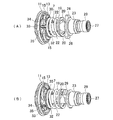
モータ4の出力軸5は、本体ハウジング2に組み付けられたギヤケース11に軸支されて、ハンマーケース6内に突出するピニオン12が嵌着されている。ハンマーケース6内において、スピンドル7は、図2にも示すように、後部に大径のキャリア部13を有し、そのキャリア部13に、インターナルギヤ14内で公転する2つの遊星歯車15,15を保持して各遊星歯車15をピニオン12に噛合させている。また、スピンドル7の後端部は、ギヤケース11に支持されるボールベアリング16によって、出力軸5と同軸で軸支されている。
An
打撃機構8は、スピンドル7の前端に外装されるハンマー17と、そのハンマー17の後面に形成されたリング溝18に前端を挿着させたコイルバネ19とを備え、ハンマー17は、スピンドル7との間に跨って嵌合するボール20,20を介してスピンドル7と連結されている。この連結は、ハンマー17の内周面に前端から後方へ向けて凹設されて後端が先細りとなる山形のカム溝21,21と、スピンドル7の外周面で先端を前方に向けて凹設されたV字状のカム溝22,22とに跨ってボール20,20が嵌合することで行われている。ハンマー17は、コイルバネ19により、ボール20が山形のカム溝21の後端とV字状のカム溝22の先端とに位置する前進位置に付勢されている。
The
アンビル9は、ハンマーケース6の前端に保持された軸受23によって中間部が軸支され、後面軸心に形成した軸受孔24に、スピンドル7の前端に突設した小径部25を嵌合させている。また、ハンマーケース6内でアンビル9の後端には、ハンマー17の前面に突設した図示しない爪が回転方向で係合する一対のフランジ26,26が放射状に延設されている。
さらに、ハンマーケース6から突出するアンビル9の前端には、図示しないビットの挿着孔27が形成されると共に、挿着孔27に挿入されたビットを抜け止め装着するボール28及びスリーブ29等を備えたチャック機構が設けられている。
The
Further, a bit insertion hole 27 (not shown) is formed at the front end of the
そして、スピンドル7のキャリア部13の前面には、コイルバネ19の後端を受けるワッシャー30が設けられている。このワッシャー30は、図3にも示すように、コイルバネ19が当接する外周部31と、その外周部31の内周縁で前方に向けて周設される立ち上げ部32とを備えたリング状で、立ち上げ部32の内径は、ハンマー17のリング溝18の内径よりも大きく形成されている。また、ワッシャー30の外周部31には、点対称位置に一対の係止片33,33が形成されている。この係止片33は、外周部31から後方へ向けて折り曲げ形成されて、ワッシャー30の半径方向に弾性を有するものとなっている。
A
一方、スピンドル7のキャリア部13の側面において係止片33,33との対応部位には、図4にも示すように、互いに平行となる面取部34,34が形成されて、各面取部34に、キャリア部13の前面にワッシャー30をセットした状態で係止片33が前方から挿入係止する凹部35がそれぞれ凹設されている。この係止片33の凹部35への係止により、ワッシャー30は、キャリア部13の前面でスピンドル7と同軸位置で、回転規制された状態で保持されることになる。これら係止片33と面取部34、凹部35がワッシャー30の位置決め手段となる。
On the other hand, on the side surface of the
以上の如く構成されたインパクトドライバ1においては、本体ハウジング2に設けた図示しないスイッチトリガーを押し込み操作してモータ4を駆動させると、出力軸5の回転が遊星歯車15,15を介してスピンドル7に伝わり、スピンドル7を回転させる。スピンドル7は、ボール20,20を介してハンマー17を回転させ、ハンマー17が係合するアンビル9を回転させるため、アンビル9の先端に装着したビットによってネジ締め等が可能となる。ネジ締めが進んでアンビル9への負荷が高まると、アンビル9に係合するハンマー17の回転とスピンドル7の回転とにずれが生じるため、ハンマー17は、ボール20,20がカム溝22,22に沿って転動することで、スピンドル7に対して相対的に回転しながらコイルバネ19の付勢に抗して後退する。
In the
そして、ハンマー17の爪がアンビル9のフランジ26,26から外れると、ハンマー17はコイルバネ19の付勢により、ボール20,20がカム溝22,22の先端に向けて転動することで回転しながら前進する。よって、爪が再びフランジ26,26に係合して回転打撃力(インパクト)を発生させる。このアンビル9への係脱をハンマー17が繰り返すことで増し締めが行われる。
また、ここでは、ハンマー17におけるリング溝18の内側がワッシャー30の立ち上げ部32とスピンドル7との間に位置するため、ハンマー17が後退する際にワッシャー30に干渉するおそれがない。よって、ワッシャー30との干渉を考慮してハンマー17を前方寄りに配置する必要がなくなる。
When the claws of the
Here, since the inside of the
このように、上記形態のインパクトドライバ1によれば、ワッシャー30を、リング溝18の内径より大きい内径を有して内周縁に前方への立ち上げ部32を周設したリング状とすると共に、キャリア部13とワッシャー30との間に、ワッシャー30をスピンドル7との同軸位置に位置決めする位置決め手段を設けたことで、コイルバネ19の後端を受けるワッシャー30と干渉することなくハンマー17の後退量を確保できる。よって、軸方向の長さを短くすることができ、コンパクト化が達成可能となる。而も、コイルバネ19の内側のスペースを有効利用してハンマー17の後退量を確保しているので、位置決め手段を設けても径方向等に大きくなることがなく、コンパクト化の妨げにならない。
Thus, according to the
特にここでは、位置決め手段を、キャリア部13の側面に形成された一対の面取部34,34と、その面取部34にそれぞれ凹設された凹部35と、ワッシャー30に形成されて凹部35に係止する一対の係止片33,33としたことで、リング状としたワッシャー30を位置ずれなく確実に位置決め可能となる。例え一方又は双方の係止片33が凹部35から逸脱することがあっても、面取部34を係止片33が押圧する格好となるため、ワッシャー30のスピンドル7に対する同軸位置は保持され、信頼性が高まる。
In particular, here, the positioning means includes a pair of
なお、立ち上げ部はワッシャーの内周縁に周設するものに限らず、周方向へ所定間隔をおいて部分的に立設する構造であっても差し支えない。
また、位置決め手段も上記形態に限らず、面取部及び係止片の数を増やしたり、面取部を省略して凹部のみを設けたりしてもよい。さらに、面取部及び凹部に代えてキャリア部の側面に所定間隔で一対の突起や突条を突設し、その突起や突条の間に係止片を係止させることもできる。
The rising portion is not limited to the one provided around the inner peripheral edge of the washer, and may be a structure that is partially provided at a predetermined interval in the circumferential direction.
Further, the positioning means is not limited to the above form, and the number of chamfered portions and locking pieces may be increased, or the chamfered portions may be omitted and only the concave portions may be provided. Furthermore, instead of the chamfered portion and the recessed portion, a pair of protrusions and protrusions can be provided at predetermined intervals on the side surface of the carrier portion, and the locking pieces can be locked between the protrusions and protrusions.
その他、例えばハウジングは本体ハウジングとハンマーケースとからなるものに限らず、本体ハウジングとハンマーケースとを一体とする等、ハウジングや打撃機構の形態等は適宜変更可能である。勿論インパクトドライバ以外に、アングルインパクトドライバやインパクトレンチ等の他の打撃工具であっても本発明は採用可能である。 In addition, for example, the housing is not limited to the main body housing and the hammer case, and the form of the housing and the striking mechanism can be changed as appropriate, for example, the main body housing and the hammer case are integrated. Of course, in addition to the impact driver, the present invention can be applied to other impact tools such as an angle impact driver and an impact wrench.
1・・インパクトドライバ、2・・本体ハウジング、4・・モータ、5・・出力軸、6・・ハンマーケース、7・・スピンドル、8・・打撃機構、9・・アンビル、13・・キャリア部、15・・遊星歯車、17・・ハンマー、18・・リング溝、19・・コイルバネ、20・・ボール、21,22・・カム溝、30・・ワッシャー、31・・外周部、32・・立ち上げ部、33・・係止片、34・・面取部、35・・凹部。
1. ・ Impact driver, 2. ・ Main body housing, 4. ・ Motor, 5. ・ Output shaft, 6. ・ Hammer case, 7. ・ Spindle, 8. ・ Blow mechanism, 9. ・ Anvil, 13. ・
Claims (3)
前記打撃機構を、前記スピンドルに外装されて前後移動可能なハンマーと、前記スピンドルとハンマーとにそれぞれ設けたカム溝間に跨って嵌合するボールと、前端が前記ハンマーの後面に形成したリング溝に挿入して前記ハンマーを前進位置に付勢するコイルバネとで形成し、前記スピンドルにおける前記コイルバネの後方に、前記モータの回転を減速する遊星歯車を保持するキャリア部を設けて、前記キャリア部の前方に前記コイルバネの後端を受けるワッシャーを配置した打撃工具であって、
前記ワッシャーを、前記リング溝の内径より大きい内径を有して内周縁に前方への立ち上げ部を立設したリング状とすると共に、前記ワッシャーに係止部を設け、前記キャリア部の側面に、前記係止部が係止する被係止部を設けて、前記係止部と前記被係止部との係止によって前記ワッシャーを前記スピンドルとの同軸位置に位置決めすることを特徴とする打撃工具。 In the housing, a motor, a spindle that rotates by driving the motor, an anvil that is coaxially supported by the housing in front of the spindle and has a front end protruding forward of the housing, and rotation of the spindle are rotated. A striking mechanism that transmits to the anvil as striking force,
A hammer that is mounted on the spindle and is movable back and forth, a ball that fits between cam grooves provided on the spindle and the hammer, and a ring groove that has a front end formed on the rear surface of the hammer. A carrier that holds a planetary gear that decelerates the rotation of the motor is provided behind the coil spring in the spindle. A striking tool in which a washer is disposed in front to receive the rear end of the coil spring,
The washer, while with the ring groove of the inner diameter erected the rising portion of the forward inner edge having a larger inner diameter ring-shaped, the engaging portion provided in the washer, the side surfaces of the carrier portions A hitting portion provided with a locked portion that is locked by the locking portion, and the washer is positioned at a coaxial position with the spindle by locking the locking portion and the locked portion; tool.
前記打撃機構を、前記スピンドルに外装されて前後移動可能なハンマーと、前記スピンドルとハンマーとにそれぞれ設けたカム溝間に跨って嵌合するボールと、前端が前記ハンマーの後面に形成したリング溝に挿入して前記ハンマーを前進位置に付勢するコイルバネとで形成し、前記スピンドルにおける前記コイルバネの後方に、前記モータの回転を減速する遊星歯車を保持するキャリア部を設けて、前記キャリア部の前方に前記コイルバネの後端を受けるワッシャーを配置した打撃工具であって、
前記ワッシャーを、前記リング溝の内径より大きい内径を有して内周縁に前方への立ち上げ部を立設したリング状とすると共に、前記ワッシャーに係止部を設け、前記キャリア部に、前記係止部が押圧して係止する被係止部を設けて、前記係止部と前記被係止部との係止によって前記ワッシャーを前記スピンドルとの同軸位置に位置決めすることを特徴とする打撃工具。 In the housing, a motor, a spindle that rotates by driving the motor, an anvil that is coaxially supported by the housing in front of the spindle and has a front end protruding forward of the housing, and rotation of the spindle are rotated. A striking mechanism that transmits to the anvil as striking force,
A hammer that is mounted on the spindle and is movable back and forth, a ball that fits between cam grooves provided on the spindle and the hammer, and a ring groove that has a front end formed on the rear surface of the hammer. A carrier that holds a planetary gear that decelerates the rotation of the motor is provided behind the coil spring in the spindle. A striking tool in which a washer is disposed in front to receive the rear end of the coil spring,
The washer has an inner diameter larger than the inner diameter of the ring groove and has a ring shape with a rising portion on the inner periphery, and a locking portion is provided on the washer. A locked portion that is pressed and locked by the locking portion is provided, and the washer is positioned at a coaxial position with the spindle by locking the locking portion and the locked portion. Blow tool.
Priority Applications (5)
| Application Number | Priority Date | Filing Date | Title |
|---|---|---|---|
| JP2010153271A JP5583500B2 (en) | 2010-07-05 | 2010-07-05 | Impact tool |
| US13/115,364 US8827003B2 (en) | 2010-07-05 | 2011-05-25 | Impact tool |
| EP20110168914 EP2404706B1 (en) | 2010-07-05 | 2011-06-07 | Impact tool |
| CN201110177496.6A CN102310380B (en) | 2010-07-05 | 2011-06-22 | Impact tool |
| RU2011127475/02A RU2011127475A (en) | 2010-07-05 | 2011-07-04 | PERCUSSION INSTRUMENT |
Applications Claiming Priority (1)
| Application Number | Priority Date | Filing Date | Title |
|---|---|---|---|
| JP2010153271A JP5583500B2 (en) | 2010-07-05 | 2010-07-05 | Impact tool |
Publications (3)
| Publication Number | Publication Date |
|---|---|
| JP2012011533A JP2012011533A (en) | 2012-01-19 |
| JP2012011533A5 JP2012011533A5 (en) | 2013-03-21 |
| JP5583500B2 true JP5583500B2 (en) | 2014-09-03 |
Family
ID=44454751
Family Applications (1)
| Application Number | Title | Priority Date | Filing Date |
|---|---|---|---|
| JP2010153271A Active JP5583500B2 (en) | 2010-07-05 | 2010-07-05 | Impact tool |
Country Status (5)
| Country | Link |
|---|---|
| US (1) | US8827003B2 (en) |
| EP (1) | EP2404706B1 (en) |
| JP (1) | JP5583500B2 (en) |
| CN (1) | CN102310380B (en) |
| RU (1) | RU2011127475A (en) |
Families Citing this family (18)
| Publication number | Priority date | Publication date | Assignee | Title |
|---|---|---|---|---|
| DE102010043099A1 (en) * | 2010-10-29 | 2012-05-03 | Robert Bosch Gmbh | Hand tool with a mechanical percussion |
| JP5825067B2 (en) * | 2011-11-18 | 2015-12-02 | マックス株式会社 | Electric tool |
| US20140091648A1 (en) | 2012-10-02 | 2014-04-03 | Makita Corporation | Electric power tool |
| US10926383B2 (en) * | 2013-03-14 | 2021-02-23 | Milwaukee Electric Tool Corporation | Impact tool |
| JP6198515B2 (en) | 2013-08-08 | 2017-09-20 | 株式会社マキタ | Impact tools |
| JP2015120206A (en) * | 2013-12-20 | 2015-07-02 | 日立工機株式会社 | Impact tool |
| GB201421576D0 (en) * | 2014-12-04 | 2015-01-21 | Black & Decker Inc | Drill |
| GB201421577D0 (en) | 2014-12-04 | 2015-01-21 | Black & Decker Inc | Drill |
| CN106393007B (en) * | 2015-07-31 | 2019-06-14 | 南京德朔实业有限公司 | Torque exports tool and its accessories apparatus |
| JP6832509B2 (en) * | 2017-03-27 | 2021-02-24 | パナソニックIpマネジメント株式会社 | Rotary striking tool |
| JP6530012B2 (en) * | 2017-06-08 | 2019-06-12 | 株式会社マキタ | Impact tool |
| AU2019221782A1 (en) | 2018-02-19 | 2020-10-08 | Milwaukee Electric Tool Corporation | Impact tool |
| US11597061B2 (en) * | 2018-12-10 | 2023-03-07 | Milwaukee Electric Tool Corporation | High torque impact tool |
| US11484997B2 (en) * | 2018-12-21 | 2022-11-01 | Milwaukee Electric Tool Corporation | High torque impact tool |
| JP7320419B2 (en) | 2019-09-27 | 2023-08-03 | 株式会社マキタ | rotary impact tool |
| JP7386027B2 (en) * | 2019-09-27 | 2023-11-24 | 株式会社マキタ | rotary impact tool |
| USD948978S1 (en) | 2020-03-17 | 2022-04-19 | Milwaukee Electric Tool Corporation | Rotary impact wrench |
| JP2023090351A (en) * | 2021-12-17 | 2023-06-29 | 株式会社マキタ | impact tool |
Family Cites Families (13)
| Publication number | Priority date | Publication date | Assignee | Title |
|---|---|---|---|---|
| JPH0831599B2 (en) * | 1985-08-19 | 1996-03-27 | セイコーエプソン株式会社 | Semiconductor device |
| JP2511323Y2 (en) * | 1990-02-09 | 1996-09-25 | 日立工機株式会社 | Impact tool |
| JP2558753Y2 (en) * | 1991-10-31 | 1998-01-14 | 株式会社マキタ | Power transmission mechanism for rotary electric tools |
| JP3402621B2 (en) * | 1992-02-21 | 2003-05-06 | 松下電工株式会社 | Impact rotary tool |
| US5269733A (en) * | 1992-05-18 | 1993-12-14 | Snap-On Tools Corporation | Power tool plastic gear train |
| JP2000006042A (en) * | 1998-06-25 | 2000-01-11 | Matsushita Electric Works Ltd | Screw fastening depth regulating device for impact turning tool |
| JP2002254336A (en) | 2001-03-02 | 2002-09-10 | Hitachi Koki Co Ltd | Power tool |
| JP2002273666A (en) * | 2001-03-19 | 2002-09-25 | Makita Corp | Rotary impact tool |
| JP3793099B2 (en) | 2002-02-12 | 2006-07-05 | 株式会社マキタ | Impact tool |
| JP4405900B2 (en) | 2004-03-10 | 2010-01-27 | 株式会社マキタ | Impact driver |
| CN101288950B (en) * | 2007-04-18 | 2011-08-03 | 苏州宝时得电动工具有限公司 | Multifunctional power tool |
| JP2009226568A (en) | 2008-03-25 | 2009-10-08 | Makita Corp | Impact tool |
| CN201208740Y (en) * | 2008-03-28 | 2009-03-18 | 南京德朔实业有限公司 | Rotating impact tool |
-
2010
- 2010-07-05 JP JP2010153271A patent/JP5583500B2/en active Active
-
2011
- 2011-05-25 US US13/115,364 patent/US8827003B2/en active Active
- 2011-06-07 EP EP20110168914 patent/EP2404706B1/en active Active
- 2011-06-22 CN CN201110177496.6A patent/CN102310380B/en active Active
- 2011-07-04 RU RU2011127475/02A patent/RU2011127475A/en not_active Application Discontinuation
Also Published As
| Publication number | Publication date |
|---|---|
| RU2011127475A (en) | 2013-01-10 |
| CN102310380B (en) | 2014-01-08 |
| JP2012011533A (en) | 2012-01-19 |
| US20120000683A1 (en) | 2012-01-05 |
| US8827003B2 (en) | 2014-09-09 |
| EP2404706B1 (en) | 2014-05-21 |
| CN102310380A (en) | 2012-01-11 |
| EP2404706A2 (en) | 2012-01-11 |
| EP2404706A3 (en) | 2013-03-20 |
Similar Documents
| Publication | Publication Date | Title |
|---|---|---|
| JP5583500B2 (en) | Impact tool | |
| US7918286B2 (en) | Impact tool | |
| JP4405900B2 (en) | Impact driver | |
| JP5468570B2 (en) | Impact tool | |
| JP4291173B2 (en) | Impact driver | |
| JP5739269B2 (en) | Electric tool with vibration mechanism | |
| JP4468786B2 (en) | Impact tools | |
| JP5744639B2 (en) | Electric tool | |
| JP6397325B2 (en) | Rotating tool | |
| JP5649500B2 (en) | Electric tool | |
| JP2011152630A (en) | Impact tool | |
| JP2018161731A (en) | Rotary impact tool | |
| JP4824812B2 (en) | Impact tools | |
| JP2017159418A (en) | Impact rotary tool | |
| JP4391921B2 (en) | Vibration drill | |
| JP2012218089A (en) | Power tool | |
| JP5284856B2 (en) | Impact tool | |
| JP2009172732A (en) | Impact rotary tool | |
| JP2012006101A (en) | Impact tool | |
| WO2018061389A1 (en) | Rotary impact tool | |
| JP2013022691A (en) | Impact rotary tool | |
| JP2019048382A5 (en) | ||
| WO2018061388A1 (en) | Rotary impact tool | |
| JP5307609B2 (en) | Impact tool | |
| WO2018061387A1 (en) | Rotary impact tool |
Legal Events
| Date | Code | Title | Description |
|---|---|---|---|
| A521 | Request for written amendment filed |
Free format text: JAPANESE INTERMEDIATE CODE: A523 Effective date: 20130201 |
|
| A621 | Written request for application examination |
Free format text: JAPANESE INTERMEDIATE CODE: A621 Effective date: 20130201 |
|
| A977 | Report on retrieval |
Free format text: JAPANESE INTERMEDIATE CODE: A971007 Effective date: 20131219 |
|
| A131 | Notification of reasons for refusal |
Free format text: JAPANESE INTERMEDIATE CODE: A131 Effective date: 20131224 |
|
| A521 | Request for written amendment filed |
Free format text: JAPANESE INTERMEDIATE CODE: A523 Effective date: 20140213 |
|
| TRDD | Decision of grant or rejection written | ||
| A01 | Written decision to grant a patent or to grant a registration (utility model) |
Free format text: JAPANESE INTERMEDIATE CODE: A01 Effective date: 20140617 |
|
| A61 | First payment of annual fees (during grant procedure) |
Free format text: JAPANESE INTERMEDIATE CODE: A61 Effective date: 20140716 |
|
| R150 | Certificate of patent or registration of utility model |
Ref document number: 5583500 Country of ref document: JP Free format text: JAPANESE INTERMEDIATE CODE: R150 |
|
| R250 | Receipt of annual fees |
Free format text: JAPANESE INTERMEDIATE CODE: R250 |
|
| R250 | Receipt of annual fees |
Free format text: JAPANESE INTERMEDIATE CODE: R250 |
|
| R250 | Receipt of annual fees |
Free format text: JAPANESE INTERMEDIATE CODE: R250 |
|
| R250 | Receipt of annual fees |
Free format text: JAPANESE INTERMEDIATE CODE: R250 |
|
| R250 | Receipt of annual fees |
Free format text: JAPANESE INTERMEDIATE CODE: R250 |
|
| R250 | Receipt of annual fees |
Free format text: JAPANESE INTERMEDIATE CODE: R250 |
|
| R250 | Receipt of annual fees |
Free format text: JAPANESE INTERMEDIATE CODE: R250 |