JP6050110B2 - Impact tools - Google Patents
Impact tools Download PDFInfo
- Publication number
- JP6050110B2 JP6050110B2 JP2012285063A JP2012285063A JP6050110B2 JP 6050110 B2 JP6050110 B2 JP 6050110B2 JP 2012285063 A JP2012285063 A JP 2012285063A JP 2012285063 A JP2012285063 A JP 2012285063A JP 6050110 B2 JP6050110 B2 JP 6050110B2
- Authority
- JP
- Japan
- Prior art keywords
- hammer
- bearing
- anvil
- spindle
- motor housing
- Prior art date
- Legal status (The legal status is an assumption and is not a legal conclusion. Google has not performed a legal analysis and makes no representation as to the accuracy of the status listed.)
- Active
Links
- 230000007246 mechanism Effects 0.000 description 11
- 230000000694 effects Effects 0.000 description 10
- 230000002093 peripheral effect Effects 0.000 description 8
- 239000000758 substrate Substances 0.000 description 8
- HBBGRARXTFLTSG-UHFFFAOYSA-N Lithium ion Chemical compound [Li+] HBBGRARXTFLTSG-UHFFFAOYSA-N 0.000 description 3
- 229910001416 lithium ion Inorganic materials 0.000 description 3
- 229910052751 metal Inorganic materials 0.000 description 3
- 239000002184 metal Substances 0.000 description 3
- 230000009467 reduction Effects 0.000 description 3
- 210000000078 claw Anatomy 0.000 description 2
- 230000002452 interceptive effect Effects 0.000 description 2
- 239000000463 material Substances 0.000 description 2
- 229920005989 resin Polymers 0.000 description 2
- 239000011347 resin Substances 0.000 description 2
- 238000004904 shortening Methods 0.000 description 2
- 238000003466 welding Methods 0.000 description 2
- XEEYBQQBJWHFJM-UHFFFAOYSA-N Iron Chemical group [Fe] XEEYBQQBJWHFJM-UHFFFAOYSA-N 0.000 description 1
- 239000004677 Nylon Substances 0.000 description 1
- 230000003139 buffering effect Effects 0.000 description 1
- 230000008859 change Effects 0.000 description 1
- 230000006835 compression Effects 0.000 description 1
- 238000007906 compression Methods 0.000 description 1
- 238000001816 cooling Methods 0.000 description 1
- 238000006073 displacement reaction Methods 0.000 description 1
- 230000017525 heat dissipation Effects 0.000 description 1
- 238000003780 insertion Methods 0.000 description 1
- 230000037431 insertion Effects 0.000 description 1
- 230000004048 modification Effects 0.000 description 1
- 238000012986 modification Methods 0.000 description 1
- 229920001778 nylon Polymers 0.000 description 1
- 230000005855 radiation Effects 0.000 description 1
- 230000004044 response Effects 0.000 description 1
- 230000001629 suppression Effects 0.000 description 1
- 229920003002 synthetic resin Polymers 0.000 description 1
- 239000000057 synthetic resin Substances 0.000 description 1
Images


Classifications
-
- B—PERFORMING OPERATIONS; TRANSPORTING
- B25—HAND TOOLS; PORTABLE POWER-DRIVEN TOOLS; MANIPULATORS
- B25B—TOOLS OR BENCH DEVICES NOT OTHERWISE PROVIDED FOR, FOR FASTENING, CONNECTING, DISENGAGING OR HOLDING
- B25B21/00—Portable power-driven screw or nut setting or loosening tools; Attachments for drilling apparatus serving the same purpose
- B25B21/02—Portable power-driven screw or nut setting or loosening tools; Attachments for drilling apparatus serving the same purpose with means for imparting impact to screwdriver blade or nut socket
- B25B21/026—Impact clutches
-
- B—PERFORMING OPERATIONS; TRANSPORTING
- B25—HAND TOOLS; PORTABLE POWER-DRIVEN TOOLS; MANIPULATORS
- B25F—COMBINATION OR MULTI-PURPOSE TOOLS NOT OTHERWISE PROVIDED FOR; DETAILS OR COMPONENTS OF PORTABLE POWER-DRIVEN TOOLS NOT PARTICULARLY RELATED TO THE OPERATIONS PERFORMED AND NOT OTHERWISE PROVIDED FOR
- B25F5/00—Details or components of portable power-driven tools not particularly related to the operations performed and not otherwise provided for
- B25F5/001—Gearings, speed selectors, clutches or the like specially adapted for rotary tools
-
- B—PERFORMING OPERATIONS; TRANSPORTING
- B25—HAND TOOLS; PORTABLE POWER-DRIVEN TOOLS; MANIPULATORS
- B25F—COMBINATION OR MULTI-PURPOSE TOOLS NOT OTHERWISE PROVIDED FOR; DETAILS OR COMPONENTS OF PORTABLE POWER-DRIVEN TOOLS NOT PARTICULARLY RELATED TO THE OPERATIONS PERFORMED AND NOT OTHERWISE PROVIDED FOR
- B25F5/00—Details or components of portable power-driven tools not particularly related to the operations performed and not otherwise provided for
- B25F5/008—Cooling means
-
- B—PERFORMING OPERATIONS; TRANSPORTING
- B25—HAND TOOLS; PORTABLE POWER-DRIVEN TOOLS; MANIPULATORS
- B25F—COMBINATION OR MULTI-PURPOSE TOOLS NOT OTHERWISE PROVIDED FOR; DETAILS OR COMPONENTS OF PORTABLE POWER-DRIVEN TOOLS NOT PARTICULARLY RELATED TO THE OPERATIONS PERFORMED AND NOT OTHERWISE PROVIDED FOR
- B25F5/00—Details or components of portable power-driven tools not particularly related to the operations performed and not otherwise provided for
- B25F5/02—Construction of casings, bodies or handles
-
- B—PERFORMING OPERATIONS; TRANSPORTING
- B25—HAND TOOLS; PORTABLE POWER-DRIVEN TOOLS; MANIPULATORS
- B25B—TOOLS OR BENCH DEVICES NOT OTHERWISE PROVIDED FOR, FOR FASTENING, CONNECTING, DISENGAGING OR HOLDING
- B25B23/00—Details of, or accessories for, spanners, wrenches, screwdrivers
- B25B23/14—Arrangement of torque limiters or torque indicators in wrenches or screwdrivers
- B25B23/1405—Arrangement of torque limiters or torque indicators in wrenches or screwdrivers for impact wrenches or screwdrivers
-
- B—PERFORMING OPERATIONS; TRANSPORTING
- B25—HAND TOOLS; PORTABLE POWER-DRIVEN TOOLS; MANIPULATORS
- B25D—PERCUSSIVE TOOLS
- B25D11/00—Portable percussive tools with electromotor or other motor drive
- B25D11/04—Portable percussive tools with electromotor or other motor drive in which the tool bit or anvil is hit by an impulse member
Description
本発明は、回転打撃動作可能であるインパクト工具に関する。 The present invention relates to an impact tool capable of rotating impact operation.
下記特許文献1に示されるように、遊星歯車機構により減速されたモータの回転力によりモータの前側のスピンドルを回転し、圧縮バネ(スプリング)により前方へ付勢された状態でスピンドル前端部に周設されたハンマにより回転力を回転打撃力に変換可能であるインパクトドライバが知られている。 As shown in Patent Document 1 below, the spindle on the front side of the motor is rotated by the rotational force of the motor decelerated by the planetary gear mechanism, and is urged forward by a compression spring (spring). There is known an impact driver capable of converting a rotational force into a rotational striking force by a provided hammer.
特許文献1のインパクトドライバでは、スピンドル後部に通される遊星歯車機構の遊星歯車の回転軸としてのピンの抜け止めを行うため、スピンドル後部の前側に、ピンを後方へ押えるワッシャが設けられている。このワッシャは、前側においてスプリングを受けており、スプリングの位置ずれを防止するため、スプリングを受ける部分のすぐ内側が前方へ膨出する形状となっている。 In the impact driver of Patent Document 1, in order to prevent the pin serving as the rotation shaft of the planetary gear of the planetary gear mechanism that is passed through the rear part of the spindle, a washer that pushes the pin rearward is provided on the front side of the rear part of the spindle. . This washer receives a spring on the front side, and in order to prevent displacement of the spring, the inside of the portion that receives the spring bulges forward.
本発明は、前後や上下の長さが従前のものに比べて、締め付けトルクを確保しつつ短く、狭い場所等において取扱い易く、又従来のピン押え用のワッシャが省略されることで、部品点数を削減し、モータハウジングの後端からアンビルの前端までの長さを短縮化することができるインパクト工具を提供することを主な目的とするものである。 The present invention, as compared with the length of the front and rear and top and bottom of the previous, shorter while securing the tightening torque, easy to handle in narrow places such as also at Rukoto washer for a conventional pin retaining is omitted, the number of parts It is a main object to provide an impact tool that can reduce the length from the rear end of the motor housing to the front end of the anvil.
上記目的を達成するために、請求項1に記載の発明は、モータと、前記モータを収容するモータハウジングと、前記モータハウジングと一体的に設けられるグリップハウジングと、前記モータハウジングの前方に配置されるハンマケースと、前記モータにより回転されるスピンドルと、前記ハンマケースの内部に収容され、前記スピンドルにより回転されるハンマと、前記ハンマケースの内部に収容され、前記ハンマにより打撃されるアンビルと、を有するインパクト工具であって、前記スピンドルに係合部が設けられており、前記係合部に係合する被係合部を有するピンが設けられており、前記ピンは、遊星歯車を保持しており、前記係合部及び前記被係合部により、前記ピンが前記ハンマ側へと移動不能になることを特徴とするものである。 In order to achieve the above object, an invention according to claim 1 is arranged in front of a motor, a motor housing that houses the motor, a grip housing that is provided integrally with the motor housing, and the motor housing. A hammer case, a spindle rotated by the motor, a hammer housed in the hammer case and rotated by the spindle, an anvil housed in the hammer case and hit by the hammer, a impact tool having has the engaging portion is provided on the spindle, which pins have a engaged portion to be engaged is provided on the engaging portion, the pin holding the planetary gears and which, by the engagement portion and the engaged portion, der which the pin is characterized by comprising immovable to the hammer side .
請求項2に記載の発明は、上記発明において、前記ハンマを付勢するためのコイルスプリングが設けられており、前記係合部及び前記被係合部は、前記コイルスプリング及び前記ハンマと干渉しない位置に配置されていることを特徴とするものである。
請求項3に記載の発明は、上記発明において、前記ピンは、遊星歯車を保持する大径部と、前記大径部よりも小径な小径部とを有し、前記係合部は、前記小径部が嵌合する凹部であることを特徴とするものである。
請求項4に記載の発明は、上記発明において、前記スピンドルに前記コイルスプリングを保持するためのバネ受け突起部が設けられており、前記ハンマの前記バネ受け突起部と対向する位置が凹んでいることを特徴とするものである。
請求項5に記載の発明は、上記発明において、前記モータの回転軸を保持可能な軸受と、前記軸受を保持し、前記ハンマケースに保持される軸受保持壁と、が設けられており、前記モータハウジングに第1の凸部が設けられており、前記軸受保持壁に第2の凸部が設けられており、前記第1の凸部の後方に前記第2の凸部が配置されており、前記第2の凸部が、前記軸受保持壁の後部であって、前記軸受の径方向外側に配置されていることを特徴とするものである。
請求項6に記載の発明は、上記発明において、前記遊星歯車と噛み合う内歯ギヤが設けられており、前記内歯ギヤは、前記ハンマケースと前方側で突き当たるように構成されており、前記軸受保持壁に、前記内歯ギヤが回転不能に設けられており、前記内歯ギヤの前記ハンマと対向する位置が凹んでいることを特徴とするものである。
請求項7に記載の発明は、上記発明において、前記ハンマケースの前部に、前記アンビルを保持するための軸受が配置されており、前記アンビルと前記ハンマケースの間にワッシャが配置されており、前記ハンマケースから前記アンビル側に延びるように突起部が設けられており、前記突起部が前記ワッシャの内径側に配置されていることを特徴とするものである。
According to a second aspect of the present invention, in the above invention, a coil spring for biasing the hammer is provided, and the engaging portion and the engaged portion do not interfere with the coil spring and the hammer. It is arranged at a position.
According to a third aspect of the present invention, in the above invention, the pin includes a large-diameter portion that holds a planetary gear, and a small-diameter portion that is smaller in diameter than the large-diameter portion, and the engaging portion is configured to have the small-diameter portion. It is a recessed part which a part fits, It is characterized by the above-mentioned.
According to a fourth aspect of the present invention, in the above invention, the spindle is provided with a spring receiving projection for holding the coil spring, and the position of the hammer facing the spring receiving projection is recessed. It is characterized by this.
According to a fifth aspect of the present invention, in the above invention, a bearing capable of holding the rotation shaft of the motor, and a bearing holding wall that holds the bearing and is held by the hammer case are provided , The motor housing is provided with a first convex portion, the bearing holding wall is provided with a second convex portion, and the second convex portion is disposed behind the first convex portion. The second convex portion is a rear portion of the bearing holding wall and is arranged on the radially outer side of the bearing.
The invention according to
The invention according to
本発明の内、請求項1に記載の発明によれば、従来のピン押え用のワッシャが省略されることで、部品点数を削減し、モータハウジングの後端からアンビルの前端までの長さを短縮化することができ、狭い場所等において極めて取扱い易いインパクト工具を提供することができる、という効果を奏する。 Of the present invention, according to the invention described in claim 1, in Rukoto washer for a conventional pin retaining is omitted, the number of components is reduced, the length from the rear end of the motor housing to the front end of the anvil The impact tool can be shortened, and an impact tool that is extremely easy to handle in a narrow place or the like can be provided.
又、請求項2に記載の発明によれば、上記発明において、上記係合部がコイルスプリング及びハンマに干渉しないようにされているため、上記効果に加えて、打撃の影響を低減して耐久性に優れた状態でモータハウジングの後端からアンビルの前端までの長さを短縮化することができる、という効果を奏する。
更に、請求項3に記載の発明によれば、上記発明において、上記係合部がピン小径部の凹部への嵌合とされているため、上記効果に加えて、モータハウジングの後端からアンビルの前端までの長さの短縮化のための上記係合部がシンプルに設けられる、という効果を奏する。
加えて、請求項4に記載の発明によれば、上記発明において、バネ受け突起部と対向するハンマ部分が凹んでいるので、上記効果に加えて、スプリングをスピンドルで直接受けることとしながらハンマの前後移動可能距離を保持し、ハンマの動作性能を維持したままモータハウジングの後端からアンビルの前端までの長さを短縮化することができる、という効果を奏する。
又、請求項5に記載の発明によれば、上記発明において、軸受保持壁の軸受保持部外側に、第1の凸部に隣接する第2の凸部が配置されているため、上記効果に加えて、軸受保持壁を強度充分に固定しながらモータハウジングの後端から前記アンビルの前端までの長さを短縮化することができる、という効果を奏する。
更に、請求項6に記載の発明によれば、上記発明において、ハンマと対向する内歯ギヤ部分が凹んでいるため、上記効果に加えて、ハンマの前後移動可能距離を保持してハンマの動作性能を維持したまま、ハンマを内歯ギアにより近付けることでモータハウジングの後端からアンビルの前端までの長さを短縮化することができる、という効果を奏する。
加えて、請求項7に記載の発明によれば、上記発明において、アンビルワッシャはアンビルの軸受ではなくハンマケース前部内に取り付けられるので、上記効果に加えて、アンビルの軸受の受け部(ローラ)の前後長さを維持してアンビルの保持を充分なものとしながら、軸受の前後長さ(ひいてはモータハウジングの後端からアンビルの前端までの長さ)を短縮化することができ、又アンビルワッシャの取り付け長さ(圧入長さ)を充分に確保することができる、という効果を奏する。
Further, according to the invention described in
Furthermore, according to the invention described in
In addition, according to the invention described in
According to the invention of
Furthermore, according to the invention described in
In addition, according to the invention described in
以下、本発明の実施の形態やその変更例を、適宜図面に基づいて説明する。
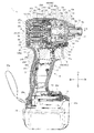
図1はネジ締め用の電動工具の一例である充電式のインパクトドライバ(回転打撃工具)1の右側面図であり、図2はインパクトドライバ1の後面図であり、図3はインパクトドライバ1の中央縦断面図であり、図4は図3の本体部の拡大図であり、図5は図3(図4)のA−A断面図であり、図6は図4のB−B断面図であり、図7は図4のC−C断面図であり、図8は図4のD−D断面図である。
インパクトドライバ1は、その外郭を形成するハウジング2を有している。尚、図1において、右が前となる。
インパクトドライバ1は、中心軸を前後方向とする筒状の本体部4と、本体部4の下部から突出するように形成されたグリップ部6を有する。
グリップ部6は、使用者が把持する部分であり、グリップ部6の基端部には、使用者による指先で引く操作が可能であるトリガ形式のスイッチレバー8が設けられている。スイッチレバー8は、スイッチ本体部8aから突出している。
Hereinafter, embodiments of the present invention and modifications thereof will be described with reference to the drawings as appropriate.
FIG. 1 is a right side view of a rechargeable impact driver (rotary impact tool) 1 as an example of an electric tool for screw tightening, FIG. 2 is a rear view of the impact driver 1, and FIG. 4 is a central longitudinal cross-sectional view, FIG. 4 is an enlarged view of the main body of FIG. 3, FIG. 5 is a cross-sectional view taken along line AA of FIG. 3 (FIG. 4), and FIG. 7 is a cross-sectional view taken along the line CC in FIG. 4, and FIG. 8 is a cross-sectional view taken along the line DD in FIG.
The impact driver 1 has a
The impact driver 1 includes a cylindrical
The
インパクトドライバ1の本体部4には、後側から順に、モータ(ブラシレスDCモータ)10、遊星歯車機構12、スピンドル14、弾性体であるコイル状のスプリング15、ハンマ16、及びアンビル18が、同軸に収納されている。
モータ10は、インパクトドライバ1の駆動源であり、その回転が遊星歯車機構12により減速された後、スピンドル14に伝達される。そして、スピンドル14の回転力がハンマ16等によって回転打撃力に変換され、適宜スピンドル14とハンマ16の間に渡されるスプリング15の緩衝を受けつつ、アンビル18に伝えられる。アンビル18は、回転打撃力を受けて軸周りに回転する部分である。
In the
The
本体部4におけるハウジング2は、モータ10を収容するモータハウジング20と、モータハウジング20の前方に配置され、ハンマ16を収容するハンマケース22を含む。
モータハウジング20は、半割筒状の左モータハウジング20a及び右モータハウジング20bと、後面となる後モータハウジング20cを含む。左モータハウジング20a及び右モータハウジング20bの各後部の上下には、吸気口20e,20eが開けられており、これらの間の後方には、それぞれ後方からネジ3を受け入れるネジボス20fが設けられている。又、後モータハウジング20cの左右には、排気口20g,20g・・が開けられている。
ハンマケース22は、前部が後部に対して縮径された筒状であり、その後部の一部がモータハウジング20の前部内に入り込んだ状態で取り付けられる。
又、モータハウジング20とハンマケース22の内側には、軸受保持壁としての皿状で金属製のベアリングリテーナ24が、これらに挟まれた状態で(ハンマケース22に保持された状態で)取り付けられている。図9にも示すベアリングリテーナ24は、中央に孔24aが開けられていると共にその孔24aの隣接部位がその外部に対して有底で低い六角柱状に窪んだ形状となっており、その窪み部24bが後へ窪む配置で、又その窪み部24bの底面が上下方向に沿う姿勢で設けられている。又、ベアリングリテーナ24の後端部(当該窪み部の後側)外縁には、これより前側に対して径方向外方へリング状に突出する外方突出リブ24cが設けられている。更に、モータハウジング20における、外方突出リブ24cの隣接位置(前側)には、モータハウジング20内面から内方へ突出する内方突出リブ20dが設けられている。ハンマケース22とベアリングリテーナ24によって、遊星歯車機構12と、ハンマケース22及びベアリングリテーナ24とが、外部からほぼ密閉された状態となる。
一方、グリップ部6におけるハウジング2は、グリップハウジング26となっている。グリップハウジング26は、モータハウジング20の下部に対して一体的に設けられている。グリップハウジング26は、それぞれ半割状である、左グリップハウジング26aと、右グリップハウジング26bを含む。左グリップハウジング26a及び右グリップハウジング26b、並びに左モータハウジング20a及び右モータハウジング20bは、ネジ3,3・・により合わせられている。
右グリップハウジング26bの上部であって、スイッチレバー8の後方には、モータ10の回転方向を切替えるスイッチである正逆切替レバー5が、本体部4とグリップ部6の境界領域において左右に貫通するように設けられている。又、スイッチレバー8の上側であって、正逆切替レバー5の前方には、前方を照射可能なライト7が設けられている。ライト7は、ここではLEDであり、スイッチレバー8と上下方向で重なるように設けられている。ライト7は、スイッチレバー8と上下方向で重なるように設けられているので、ライト7の照射方向に使用者の指等が位置せずに、ライト7の照射を妨げる事態の発生を防止し、ライト7点灯時の視認性を良好なものとすることができる。
グリップハウジング26の下端部は、その上部に対して主に前方へ広がる電池取り付け部26cとなっており、電池取り付け部26cの下方には、押しボタン28aにより着脱可能にバッテリ28が保持されている。バッテリ28は、ここでは14.4V(ボルト)のリチウムイオンバッテリである。
電池取り付け部26cの上部の前部には、表示スイッチ付き表示部26d(ここではLEDによる表示部である)が設けられている。又、電池取り付け部26cの上部の左右には、図示しないフックを取り付け可能であるフック用溝26eと、フックを始めとするネジを有する別部材を取り付け可能であるネジ穴26fが開けられている。尚、電池取り付け部26cの後部には、ストラップ26gが設けられている。又、電池取り付け部26cの内部には、回路基板51が収められている。回路基板51には、後述の各駆動コイル17に対応して設けられ、対応する駆動コイル17のスイッチングを行う、図示しない6個のスイッチング素子が搭載されている。
The
The
The
Further, a dish-shaped
On the other hand, the
A forward /
The lower end portion of the
A display unit with a
モータ10は、ブラシレスDCモータであり、固定子鉄心9と、固定子鉄心9の前後に設けられる前絶縁部材11及び後絶縁部材13と、前絶縁部材11及び後絶縁部材13を介して固定子鉄心9にそれぞれ巻かれる複数(ここでは6個)の駆動コイル17,17・・と、を有するステータ19を備える。又、前絶縁部材11には、センサ基板31がネジ21,21で固定されている。センサ基板31の後面には、ここでは3個の磁気センサ31a,31a・・(図8参照)が固定されている。更に、前絶縁部材11の前面周縁には、各駆動コイル17とセンサ基板31を電気的に接続する接点としてのコイル接続部11a,11a・・が、合計6個設けられている。
ステータ19の内部には、ロータ29が配置されている。ロータ29は、回転軸としてのロータ軸30と、ロータ軸30の周囲に配置された筒状の回転子鉄心23と、回転子鉄心23の外側に配置されており、筒状で周方向に極性を交互に変えた永久磁石25と、これらの前側(センサ基板31側)において放射状に配置された複数のセンサ用永久磁石27,27・・と、を有する。回転子鉄心23と、永久磁石25と、センサ用永久磁石27,27・・は、ロータアッセンブリ29aを構成する。ロータアッセンブリ29aは、スイッチ本体部8aの上方に配置されており、この配置によって、バランスが良く、握った際に使い易いインパクトドライバ1とすることができる。
ロータ軸30における回転子鉄心23の前側には、筒状の樹脂スリーブ35が設けられている。樹脂スリーブ35の前方には、ロータ軸30の前の軸受36が設けられている。又、軸受36の前方であって、ロータ軸30の前端部には、ピニオン37が固定されている。ロータ軸30の回転子鉄心23の後方には、金属製のインサートブッシュ39を介して冷却用のファン32が取り付けられている。インサートブッシュ39は圧入されており、ファン32のロータ軸30に対する固定力が高いものとなる。軸受36は、本体部4における上部のネジ3と、本体部4における下部(の中央)のネジ3の、それぞれの中心を結んだ直線上に配置されている。よって、ロータ軸30の振動を効果的に抑制することができる。
特に図8に示すように、センサ基板31の周縁側部には、4個の貫通孔41,41・・が開けられており、センサ基板31の周縁上部には、周方向内側に入る1個の小凹部43が設けられている。一方、前絶縁部材11の前部には、各貫通孔41や凹部43の何れかに対応する5個の前方への小突起45,45・・が設けられている。そして、各貫通孔41及び凹部43には、対応する小突起45が入っている。又、センサ基板31の周縁側部には、周方向内側に入る2個の凹部47が設けられており、各凹部47には上述のネジ21,21が入る。
ファン32は、ロータ軸30隣接部(内側)がその外部(外側)に対して前方に膨出した形状(中央部に前方へ膨出する膨出部32aを有する形状)となっている。そして、ロータ軸30の後の軸受34が、その膨出部32aの後側(その外部の内側)に一部を入れた状態で、後モータハウジング20c内面に設置されている。後モータハウジング20cには、排気口20g,20g・・が配置されており、又排気口20g,20g・・は、ファン32の径方向外側に配置されている。よって、ファン32の風は、効率的に排出される。又、排気口20g,20g・・は、ネジボス20fに受け入れられる各ネジ3の上下に配置されている。よって、開口部である排気口20g,20g・・に隣接する部位であるネジボス20fやネジ3において後モータハウジング20cが取り付けられ、後モータハウジング20cの組み付け後の強度が向上する。
The
A
A
In particular, as shown in FIG. 8, four through
The
又、主に図7や図9に示すように、ベアリングリテーナ24は、前絶縁部材11に係る2個のネジ21,21及び4個(最も上側のもの以外)の小突起45,45・・と、軸方向において重なる位置となるように(オーバーラップさせて)配置されている。このため、ネジ21,21や小突起45,45・・よりも前方にベアリングリテーナ24を配置させる場合に比べて、本体部4の前後方向の長さが短縮化される。
更に、ベアリングリテーナ24の前部外縁から前方へ突出する前方突出壁24dが設けられており、その外周面には、図示しない雄ネジ山が形成されている。一方、ハンマケース22の後端部の内周面には、図示しない雌ネジ溝が形成されている。そして、この雌ネジ溝に対して雄ネジ溝が噛み合うことにより、ベアリングリテーナ24がハンマケース22に固定される。尚、ベアリングリテーナ24の後部の窪み部24bは、六角柱状であるから、レンチ等の利用によりハンマケース22に対してベアリングリテーナ24を回転させ易く、雌ネジ溝に対して雄ネジ山を進行させ易く、よってハンマケース22にベアリングリテーナ24を取り付け易くなっている。
又、ロータ軸30の前の軸受36は、ベアリングリテーナ24の孔24aの後部に入る状態で設置されている。ベアリングリテーナ24の窪み部24bの後面(軸受36の外方)には、複数の凹み部49a,49a・・が周方向に並ぶ状態で形成されており、凹み部49a,49aの各間には、後方に立つ小壁状のリブ49bが形成されている。他方、ベアリングリテーナ24の窪み部24bの内側において、スピンドル14の後端部14aを受ける軸受40が設置されている。凹み部49a,49a・・は、軸受40の方向に位置している。この凹み部49a,49a・・、あるいはこれらとリブ49b,49b・・により、ベアリングリテーナ24の放熱が好適に行われる。尚、ベアリングリテーナ24は金属製であるため、更に放熱に適している。
加えて、ベアリングリテーナ24における軸受36よりも前方側の位置(窪み部24内の軸受36外側)には、前方へ突出する前方突出部24e,24e・・が、放射方向に沿うような筋状に複数形成されている。この前方突出部24e,24e・・によってもベアリングリテーナ24の放熱が好適に行われる。この前方突出部24e,24e・・は、軸受40の内径側に入っており、軸受40と軸方向においてオーバーラップしている。
As shown mainly in FIGS. 7 and 9, the bearing
Further, a
Further, the bearing 36 in front of the
In addition,
スピンドル14は、その後部であって後端部の前側において、中空の円盤状部14bを備えている。円盤状部14bは、スピンドル14の他の部分に対して、外方(上下左右)に突出しており、径が他の部分より長くなっている。
ベアリングリテーナ24における、円盤状部14bと対向する部分には、凹み部24f,24f・・が設けられている。各凹み部24fは、軸受40の外側まで延ばされている。これらの凹み部24f,24f・・により、ベアリングリテーナ24の放熱が好適に行われる。
The
In the bearing
スピンドル14の円盤状部14b内には、遊星歯車機構12の一部が配置されている。
遊星歯車機構12は、内歯を有する内歯ギヤ42と、内歯ギヤ42に噛み合う外歯を有する複数の遊星歯車44,44・・と、各遊星歯車44の軸である各ピン46とを含む。
内歯ギヤ42は、後部における筒状の歯部42aに対して、これより前側の前部42bが内外径とも拡径するように形成されており、この拡径により、前部42b内周側において凹部42cが設けられる。
特に図6に示されるように、前部42bには4個の凸部42d,42d・・が設けられており、ハンマケース22内側には対応する4個の凹部22c,22c・・が設けられていて、各凸部42dが、対応する凹部22cに入ることで、これらが互いに係合されている。このような係合における前後方向の長さを十分に確保するため、ハンマ16の最後退位置の外周側まで各凸部42dが達するように形成されている。
又、凹部42cは、径方向においてハンマ16外周部と同様の位置に配置されて、凹部42cにより、内歯ギヤ42におけるハンマ16と対向する位置が凹み、換言すれば、内歯ギヤ42の前部42b内径はハンマ16外径より大きく形成されて、前部42bはハンマ16と干渉しないように形成されている。内歯ギヤ42は、ベアリングリテーナ24の前部とハンマケース22の後端縁とが重なっている部位の内側において回転不能に取り付けられている。内歯ギヤ42の前面は、ハンマケース22の後端縁において後部が前部より僅かに拡径することで形成された段部22aに当たっており、内歯ギヤ42は、ハンマケース22と前方側で突き当たる。尚、歯部42aの外側であって、モータハウジング20の内側には、ベアリングリテーナ24の前方突出壁24dが入り込んでいる。
各遊星歯車44の大部分及び各ピン46は、スピンドル14の円盤状部14b内方に配置される。
各ピン46は、前端部がこれより後の部分に対して縮径するように形成されており、即ち小径部46aの後側に大径部46bが位置するようになっている。一方、スピンドル14の円盤状部14bの前面には、各ピン46の小径部46aに対応するピン孔14cが複数(ピン46の数だけ)設けられる。又、円盤状部14bの後面には、各ピン46の大径部46bの後端部に対応するピン孔14dが複数設けられる。そして、各ピン46は、小径部46aをピン孔14cに入れると共に、大径部46bの後端部をピン孔14dに入れた状態で、円盤状部14b内に設けられる。各ピン46は、小径部46aをピン孔14cに合わせることで、小径部46aと大径部46bの間の段差が円盤状部14b内面(ピン孔14cの内周縁)に当たるようになり、もってハンマ16側への移動が不能である状態となる。
各遊星歯車44は、対応するピン46の周りで回転可能である状態で、ピン46に周設される。各遊星歯車44は、外歯の一部が円盤状部14bから外方へ出るように配置されている。
A part of the
The
The
In particular, as shown in FIG. 6, the
Further, the
Most of each
Each
Each
スピンドル14の内部であって、円盤状部14bの前後には、後面から前方への穴であるスピンドル穴が設けられている。当該スピンドル穴は、その前部である前方側穴14eと、その後方に設けられ、前方側穴14eよりも大径である後方側穴14fを有する。後方側穴14fが前方側穴14eよりも大径であるので、ピニオン37を遊星歯車44,44・・に噛み合わせるためこれらの穴に入れる際に、ピニオン37が後方側穴14fに当たり難くなる。又、前方側穴14eが後方側穴14fよりも小径であるので、スピンドル14に掛かるトルクに対し耐久性を好適に持たせられる。
スピンドル穴後部(前方側穴14eの後部及び後方側穴14f)内方には、モータ10のロータ軸30の先端部が入り、ロータ軸30先端部のピニオン37には、全ての遊星歯車44と共通して噛み合う歯が形成されている。後方側穴14fの径は、ロータ軸30の軸受36の外径より大きくなっている。
又、スピンドル14の円盤状部14bの前面外縁には、前後方向に沿う低いバネ受け突起部14gが、円盤状部14bと一体的に設けられている。
バネ受け突起部14gはリング状であり、スプリング15のリング状に形成された後端部が、バネ受け突起部14gの内側に配置されていて、バネ受け突起部14gはスプリング15を受けるバネ受けとなっている。そして、スプリング15の内側に、ピン孔14dが配置されており、スプリング15の後方に、ピン46の小径部46aが配置されている。
バネ受け突起部14gは、内歯ギヤ42の内側に入っており、前後方向においてバネ受け突起部14gやスプリング15(の後端部)と内歯ギヤ42がオーバーラップしている。
バネ受け突起部14gの前端よりも後方に、ピニオン37の前端が配置される。よって、ピニオン37を短く構成することができ、ピニオン37にかかる材料費を抑制することができる。又、内歯ギヤ42の前端よりも後方に、ピニオン37の前端が配置される。よって、ピニオン37を短く構成することができ、ピニオン37にかかる材料費を抑制することができる。
スピンドル14の後端部14aを受ける軸受40の内径は、ベアリングリテーナ24により保持される軸受36の外径より大きくなっている。又、軸受40の後面は、軸受36の前面より前にあり、軸受40と軸受30は前後方向において互いにずれた状態で配置されている。よって、スピンドル14から軸受40に伝わった力が、軸受36に伝わり難くなり、軸受36やベアリングリテーナ24が長寿命になる。
A spindle hole, which is a hole from the rear surface to the front, is provided inside the
The tip of the
Further, a low
The
The
The front end of the
The inner diameter of the
一方、ハンマ16は、後面から前方へ筒状に窪む窪み16aを有しており、窪み16aには、スプリング15の前部が入っていて、窪み16aの底(前端)には、複数のボール50,50・・及びハンマワッシャ52を介して、スプリング15のリング状に形成された前端部が配置されている。
窪み16aの後端縁外側(開口部外側)には、これより前側における外側の面に対してより外側へ広がるバネ受け逃げ部16bが設けられている。バネ受け逃げ部16bとスピンドル14のバネ受け突起部14gは、筒状の本体部4の内外の方向(径方向)において同様の位置に配置されており、たとえハンマ16が後方に移動して円盤状部14b前側に隣接したとしても、バネ受け逃げ部16bがバネ受け突起部14gを避けることで、ハンマ16とスピンドル14が干渉しないようにされている。
又、窪み16aは、径方向においてピン孔14dやピン46の小径部46aと同様な位置に配置されており、たとえハンマ16が後方に移動して円盤状部14b前側に隣接したとしてもピン孔14dや小径部46aがハンマ16と干渉しない位置に配置されている。
尚、ハンマ16とスピンドル14の前部との間には、打撃時にハンマ16を主に前後方向に案内するボール54,54が介装されている。
On the other hand, the
On the outer side of the rear end edge of the
The
In addition, between the
ハンマ16前側のアンビル18は、放射方向にそれぞれ延びる一対の延設部18a,18aを、後端部に有している。
延設部18a,18aの前側には、アンビル18を軸周りに回転自在且つ軸方向に変位不能に支持するアンビル軸受60が設けられている。アンビル軸受60は、ハンマケース22の前端部内壁に取り付けられる。
又、アンビル18の後部中央には、後面から前方への穴である後穴18bが開けられており、後穴18bには、回転打撃力を伝達可能な状態で、スピンドル14の前端部が入れられている。
他方、アンビル18の前部には、図示しないビット(先端工具)を受け入れるチャック部18cが設けられている。
アンビル18の延設部18a,18aの外縁とハンマケース22の前内壁との間には、アンビル18を受ける、合成樹脂(ナイロン)製のアンビルワッシャ62が配置されている。リング状のアンビルワッシャ62の内壁のすぐ内側には、ハンマケース22の前内壁から前方へリング状に突出するワッシャ保持部22bが設けられており、アンビルワッシャ62はワッシャ保持部22bへ圧入又は保持されている。
アンビル18の後面よりも後方において、スイッチレバー8の前端が配置されている。よって、打撃を受ける部分と使用者が操作するスイッチレバー8との位置関係を適切なものとして扱い易いインパクトドライバ1とすることができる。
The
An anvil bearing 60 is provided on the front side of the extending
Further, a
On the other hand, a
An
The front end of the
このようなインパクトドライバ1の動作例を説明する。
作業者がグリップ部6(グリップハウジング26)を把持してスイッチレバー8を引くと、スイッチ本体部8aにおける切替によりバッテリ28からモータ10への給電がなされ、ロータ軸30が回転する。
ロータ軸30の回転により、ファン32が回転し、吸気口20e,20eから排気口20g,20g・・への空気の流れが形成される。この際、空気の流れによって、まず固定子鉄心9の外周が冷却される。次いで、センサ基板31の全面が冷却される。続いて、回転子鉄心23、各駆動コイル17及び固定子鉄心9の内周が冷却される。
又、ロータ軸30の回転力は、内歯ギヤ42内を自転しながら走る遊星ギア44,44・・により減速されたうえで、ピン46,46・・を介し、スピンドル14に伝わる。
スピンドル14は、アンビル18を回転させると共に、アンビル18において所定閾値以上のトルクを受けた場合にハンマ16を前後に揺動(打撃)するように案内する。打撃時には、スプリング15による緩衝作用がハンマ16(やスピンドル14)に働く。
An operation example of such an impact driver 1 will be described.
When the operator holds the grip portion 6 (grip housing 26) and pulls the
The rotation of the
Further, the rotational force of the
The
以上のインパクトドライバ1では、次にそれぞれ挙げるような単独のそれぞれの構成あるいはその組合せにより、モータハウジング20の後端からアンビル18の前端までの長さ(以下「本体部4の前後長さ」という)を短くすることができる。結果、本体部4の前後方向の長さを従前(129mm)よりも短く(それぞれの採用する構成の組合せにより、128mm以下、125mm以下、あるいは120mm以下に)することが可能となる。尚、図1〜4で表したインパクトドライバ1における本体部4の前後長さは、119.7mmである。
即ち、スピンドル14の円盤状部14bに、係合部としてのピン孔14cを設けると共に、ピン孔14cに係合する被係合部としての小径部46aを有し、遊星歯車44を保持するピン46を設け、ピン孔14c及び小径部46aにより、ピン46がハンマ16側へと移動不能になる。この構成により、従来のワッシャ102を別途ピン46の前に設けなかったとしても、ピン46のハンマ16側への移動を抑制することができ、ワッシャ102の省略を可能として、部品点数の削減を図ることができ、又その分本体部4の前後長さを短くすることができる。
更に、ピン46は、遊星歯車44を保持する大径部46bと、大径部46bよりも小径な小径部46aとを有し、ピン孔14cは、小径部46aが嵌合する凹部である。この構成により、本体部4の前後長さの短縮化等のためにワッシャ102を省略したとしても、ピン46の移動抑制をシンプルに実現することができる。
In the above impact driver 1, the length from the rear end of the
That is, the pin-shaped
Further, the
加えて、スピンドル14にスプリング15を保持するためのバネ受け突起部14gを設け、ハンマ16のバネ受け突起部14gと対向する位置を窪み16aのバネ受け逃げ部16bにより凹ませた。この構成により、スプリング15を充分に保持することができ、スプリング15とバネ受け突起部14gの干渉を防止してこれらを保護することができる。
又、モータ10のロータ軸30を保持可能な軸受36を設け、軸受36を保持し、ハンマケース22に保持される軸受保持壁としてのベアリングリテーナ24を設け、モータハウジング20に第1の凸部としての内方突出リブ20dを設け、ベアリングリテーナ24に第2の凸部としての外方突出リブ24cを設け、内方突出リブ20dの後方に外方突出リブ24cを配置し、外方突出リブ24cを、ベアリングリテーナ24の後部であって、軸受36の径方向外側に配置した。この構成により、外方突出リブ24cの後方に軸受36を配置する場合に比べてベアリングリテーナ24の前後長さを短縮化でき、もって本体部4の前後長さの短縮化を図ることができる。又、内方突出リブ20dに接触する外方突出リブ24cは依然として設けられるため、本体部4の前後長さを短縮化しても強度を維持することができる。
更に、遊星歯車44と噛み合う内歯ギヤ42を設け、内歯ギヤ42を、ハンマケース22と前方側で突き当たるように構成し、ベアリングリテーナ24に、内歯ギヤ42を回転不能に設け、内歯ギヤ42におけるハンマ16と対向する位置を凹ませた(内歯ギヤ42に凹部42cを設けた)。この構成により、ハンマ16につき、内歯ギヤ42に干渉することなく、前後方向において内歯ギヤ42とオーバーラップする位置(ハンマ16後端部が内歯ギヤ42の前部42b内側に入る位置)まで移動可能とすることができ、内歯ギヤ42に凹部42cを設けない場合と比べ、ハンマ16の移動距離を維持しながら内歯ギヤ42とハンマ16の前後間隔を狭めることができ、その分本体部4の前後長さを短縮化できる。
又更に、ハンマケース22の前部に、アンビル18を保持するための軸受60を配置し、アンビル18とハンマケース22の間にアンビルワッシャ62を配置し、ハンマケース22からアンビル18側に延びるように突起部としてのワッシャ保持部22bを設け、ワッシャ保持部22bをアンビルワッシャ62の内径側に配置した。この構成により、軸受60に突起部を設けなくてもアンビルワッシャ62を取り付けることができ、ワッシャ保持部22bの取り付け長さ(圧入長さ)を十分に確保しながら軸受60の前後長さを短縮化でき、もって本体部4の前後長さを短縮化できる。
加えて、ベアリングリテーナ24の外方突出リブ24cの内部に凹み部49a,49a・・を設けた。この構成によって、ハンマ16の前後動や回転により誘起され、ベアリングリテーナ24から受ける、径方向への回転衝撃や軸方向への軸衝撃を、効果的に緩衝することができる。
In addition, a
Further, a
Further, an
Furthermore, a
In addition, recesses 49a, 49a,... Are provided inside the outward projecting
尚、モータハウジング20は、後面となる後モータハウジング20cを含んでおり、後モータハウジング20cを他のモータハウジング20の部分(後部以外の部分)に対して独立させている。この構成により、モータハウジング20の内部空間の大きさを維持しながらモータハウジング20の後方への膨出を抑制することができ、本体部4の前後長さを短くすることができる。
又、ファン32を、径方向内側がその外側に対して前方に膨出した形状とし、ファン32に隣接する軸受34を、ファン32の膨出部32aの内側に入るように配置した。この構成により、平坦なファン32の後に軸受34を配置する場合に比べて軸受34をファン32に近付けることができ、もって本体部4の前後長さが短縮化される。
加えて、スピンドル穴14eの径を、ロータ軸30の軸受36の外径より大きくする。この構成により、スピンドル14や前後長さの短いベアリングリテーナ24の組み付け後においても、スピンドル穴14eのスペースを適宜利用することで軸受36付きのモータ10を組み付けることができ、本体部4の前後長さの短いインパクトドライバ1を容易に組み立てることができる。
又、特に図4や図5に示すように、左モータハウジング20aにはネジボス20fが設けられており、右モータハウジング20bにもネジボス20fが設けられている。各ネジボス20fは、前後方向に延びている。この2個のネジボス20f,20fに対して、合計2本のネジ3,3によって、後モータハウジング20cが固定されるようになっており、本体部4における前後方向の長さが短縮化される。更に、2本のネジ3,3に挟まれるように、軸受34,ファン32,後絶縁部材13,固定子鉄心9,ロータ軸30,永久磁石25が配置されており、このような構成によっても、本体部4における前後方向の長さを短縮化することができる。
The
Further, the
In addition, the diameter of the
In particular, as shown in FIGS. 4 and 5, the
そして、これらの構成の適宜選択のうえでの採用により、モータ10と、モータ10を収容するモータハウジング20と、モータハウジング20と一体的に設けられるグリップハウジング26と、モータハウジング20の前方に配置されるハンマケース22と、モータ10により回転されるスピンドル14と、ハンマケース22の内部に収容され、スピンドル14により回転されるハンマ16と、ハンマケース22の内部に収容され、ハンマ16により打撃されるアンビル18と、を有するインパクトドライバ1であって、モータハウジング20の後端からアンビル18の前端までの長さ(本体部4の前後長さ)を、128(あるいは125,120)mm以下としたインパクトドライバ1を構成することができる。尚、本体部4の前後長さの実用的な下限は、115mm(あるいは110mm)である。
And by adopting these configurations as appropriate, they are arranged in front of the
又、本体部4の前後長さが短縮化されることにより、グリップハウジング26の上下長さが短くても本体部4を充分に支えることが可能となる。よって、グリップハウジング26の下方にバッテリ28が保持されたインパクトドライバ1にあって、バッテリ28の下端からモータハウジング20の上端までの長さを300(あるいは250,235)mm以下として構成することができる。尚、実用的な当該長さの下限は、230mm(あるいは200mm)である。
更に、インパクトドライバ1の重さ(バッテリを含む)は、好ましくは、2.0kg(キログラム)以下、更に好ましくは1.5kg以下、あるいは1.4kg以下に構成することが可能である。
又、このようなインパクトドライバ1では、少なくとも150Nm(ニュートンメートル)のトルクを出力可能であり、より好ましくは160Nm以上のトルクを出力可能としても良く、170Nm以上のトルクを出力可能に構成することも可能である。
尚、バッテリ28の後面よりも前方側に、電池取り付け部26cの後端及びモータハウジング20の後端が配置されている。又、電池取り付け部26cの後端よりも前方側に、モータハウジング20の後端が配置されている。よって、電池取り付け部26cの後端や、モータハウジング20の後端が、作業の邪魔になり難いように構成されている。
Further, by shortening the front-rear length of the
Furthermore, the weight (including the battery) of the impact driver 1 is preferably 2.0 kg (kilograms) or less, more preferably 1.5 kg or less, or 1.4 kg or less.
Further, such an impact driver 1 can output a torque of at least 150 Nm (Newton meter), more preferably can output a torque of 160 Nm or more, and can be configured to output a torque of 170 Nm or more. Is possible.
Note that the rear end of the
このように、インパクトドライバ1の前後や上下の長さが短縮化されると、狭い場所等における衝突の発生や無理な姿勢での作業の可能性が低減された、取扱い易いインパクトドライバ1の提供が可能となる。 As described above, when the length of the impact driver 1 is shortened before and after or vertically, the impact driver 1 that is easy to handle is provided, in which the possibility of collision in a narrow place or the like and the possibility of work in an unreasonable posture is reduced. Is possible.
尚、本発明は上記形態に限定されず、例えば次のような変更を適宜施すことができる。
遊星歯車機構とスピンドルの係合に関し、ピン小径部のピン孔への挿入に代えて、あるいはこれと共に、小突起の小孔への挿入や、爪同士の係止等とする。又、底のないピン孔に代えて、有底のピン穴とすることもできる。
スピンドルのバネ受けに関し、コイルスプリングの外径側が支持されることで保持されるものに代えて、コイルスプリングの内径側を保持されるものとしたり、コイルスプリングの外径側あるいは内径側に圧入されることで保持されるものとしたり、ネジを用いてコイルスプリングがスピンドルに螺着されることで保持されるものとしたり、コイルスプリングとスピンドルが溶接されることで保持されるものとしたり、これらの組合せとしたりする。
ハンマのバネ受け逃げ部を、後方への拡径形状以外の形状により形成する。
軸受保持壁としてのベアリングリテーナにおいて外歯ギヤを保持せず、外歯ギヤは別のハウジングで保持するようにする。
アンビルワッシャの取り付けにつき、圧入に代えて、爪とその係止部による係合や、溶接等とする。
実施例においては、電池取り付け部の内部に配置される回路基板上に6個のスイッチング素子を配置する構成とした。しかし、センサ基板上に6個のスイッチング素子を配置する構成とすることも可能である。又、ファンは、前絶縁部材よりも前方に配置し、センサ基板は、後絶縁部材の後方に配置させた状態で、後絶縁部材にネジ止めすることも可能である。
バッテリは、18V(最大20V),18V,25.2V,28V,36V等の18〜36Vの任意のリチウムイオンバッテリを用いても良いし、14.4V未満あるいは36Vを超える電圧のリチウムイオンバッテリを用いても良いし、他の種類のバッテリを用いても良い。
ロータアッセンブリにおける永久磁石及びセンサ用永久磁石は、一体で構成することにより、4個の板状の永久磁石にすることも可能である。
ハンマケースに代えてギアケースを採用し、ハンマ及びアンビルを省略して、更に例えば2段階の遊星歯車機構等の減速機構部を配置して、減速機構部の出力軸をギヤケースから前方へ突出させて、先端工具を保持する先端工具保持部を出力軸の前部に固定することにより、充電式のドライバドリル又は振動ドライバドリルとすることも可能である。
ハウジングの区分の数や外歯ギヤの設置数を増減したり、バネ受け突起部の位置をより内側にしたり、スイッチレバーのスイッチの形式を変更したりする等、各種部材の数や配置、材質、大きさ、形式等を適宜変更することができる。
In addition, this invention is not limited to the said form, For example, the following changes can be given suitably.
With respect to the engagement between the planetary gear mechanism and the spindle, instead of or together with the insertion of the small pin portion of the pin into the pin hole, the small protrusion is inserted into the small hole or the claws are engaged. Moreover, it can also be set as a pin hole with a bottom instead of a pin hole without a bottom.
Regarding the spring receiver of the spindle, the inner diameter side of the coil spring is held instead of the one supported by the outer diameter side of the coil spring, or the outer diameter side or inner diameter side of the coil spring is press-fitted. It is assumed that the coil spring is held by being screwed to the spindle using a screw, the coil spring is held by welding the spindle, Or a combination.
The spring receiving relief portion of the hammer is formed by a shape other than the rearward enlarged diameter shape.
The external gear is not held in the bearing retainer as the bearing holding wall, and the external gear is held by another housing.
When the anvil washer is attached, instead of press-fitting, engagement by a claw and its engaging portion, welding, or the like is used.
In the embodiment, six switching elements are arranged on the circuit board arranged inside the battery mounting portion. However, a configuration in which six switching elements are arranged on the sensor substrate is also possible. In addition, the fan may be disposed in front of the front insulating member, and the sensor board may be screwed to the rear insulating member in a state of being disposed behind the rear insulating member.
As the battery, any lithium ion battery of 18 to 36V such as 18V (maximum 20V), 18V, 25.2V, 28V, 36V, etc. may be used, and a lithium ion battery having a voltage of less than 14.4V or more than 36V may be used. You may use and another kind of battery may be used.
The permanent magnet and the sensor permanent magnet in the rotor assembly can be made into four plate-like permanent magnets by forming them integrally.
Use a gear case instead of a hammer case, omit the hammer and anvil, and place a reduction mechanism such as a two-stage planetary gear mechanism, for example, so that the output shaft of the reduction mechanism protrudes forward from the gear case. Thus, by fixing the tip tool holding portion for holding the tip tool to the front portion of the output shaft, a rechargeable driver drill or a vibration driver drill can be provided.
Increase / decrease the number of housing sections and external gears, make the position of the spring receiving projection more inside, change the switch type of the switch lever, etc. The size, format, etc. can be changed as appropriate.
1・・インパクトドライバ(インパクト工具)、10・・モータ、14・・スピンドル、14c・・ピン孔(係合部、凹部)、14g・・バネ受け突起部、15・・スプリング(コイルスプリング)、16・・ハンマ、16b・・バネ受け逃げ部、18・・アンビル、20・・モータハウジング、20d・・内方突出リブ(第1の凸部)、22・・ハンマケース、22b・・ワッシャ保持部(突起部)、24・・ベアリングリテーナ(軸受保持壁)、24c・・外方突出リブ(第2の凸部)、26・・グリップハウジング、28・・バッテリ、30・・(モータの)ロータ軸(回転軸)、36・・(ロータ軸の)軸受、42・・内歯ギア、44・・遊星歯車、46・・ピン、46a・・小径部(被係合部)、46b・・大径部、60・・(アンビルの)軸受、62・・アンビルワッシャ。 1. ・ Impact driver (impact tool), 10 ・ ・ Motor, 14 ・ Spindle, 14c ・ ・ Pin hole (engagement part, recess), 14g ・ ・ Spring receiving projection, 15 ・ ・ Spring (coil spring), 16 .. Hammer, 16 b .. Spring receiving relief part, 18 .. Anvil, 20 .. Motor housing, 20 d .. Inward projecting rib (first convex part), 22 .. Hammer case, 22 b. Part (projection part), 24 .. bearing retainer (bearing holding wall), 24 c .. outward projecting rib (second convex part), 26 .. grip housing, 28 .. battery, 30. Rotor shaft (rotary shaft), 36 .. (rotor shaft) bearing, 42 .. Internal gear, 44 .. Planetary gear, 46 .. Pin, 46 a .. Small diameter portion (engaged portion), 46 b. Large diameter part, 60 ... Building of) bearing, 62 ... anvil washer.
Claims (7)
前記モータを収容するモータハウジングと、
前記モータハウジングと一体的に設けられるグリップハウジングと、
前記モータハウジングの前方に配置されるハンマケースと、
前記モータにより回転されるスピンドルと、
前記ハンマケースの内部に収容され、前記スピンドルにより回転されるハンマと、
前記ハンマケースの内部に収容され、前記ハンマにより打撃されるアンビルと、
を有するインパクト工具であって、
前記スピンドルに係合部が設けられており、
前記係合部に係合する被係合部を有するピンが設けられており、
前記ピンは、遊星歯車を保持しており、
前記係合部及び前記被係合部により、前記ピンが前記ハンマ側へと移動不能になる
ことを特徴とするインパクト工具。 A motor,
A motor housing that houses the motor;
A grip housing provided integrally with the motor housing;
A hammer case disposed in front of the motor housing;
A spindle rotated by the motor;
A hammer housed in the hammer case and rotated by the spindle;
An anvil housed in the hammer case and struck by the hammer;
An impact tool having
An engaging portion is provided on the spindle,
A pin to have the engaged portion to be engaged is provided on the engaging portion,
The pin holds a planetary gear,
The engagement by the engaging portion and the engaged portion, the impact tool wherein the pin is characterized by comprising immovable to the hammer side.
前記係合部及び前記被係合部は、前記コイルスプリング及び前記ハンマと干渉しない位置に配置されていることを特徴とする請求項1記載のインパクト工具。 A coil spring for biasing the hammer is provided ;
The impact tool according to claim 1, wherein the engaging portion and the engaged portion are disposed at positions that do not interfere with the coil spring and the hammer.
前記係合部は、前記小径部が嵌合する凹部であることを特徴とする請求項1又は請求項2記載のインパクト工具。 The pin has a large-diameter portion that holds the planetary gear, and a small-diameter portion that is smaller in diameter than the large-diameter portion,
The impact tool according to claim 1, wherein the engagement portion is a recess into which the small diameter portion is fitted.
前記ハンマの前記バネ受け突起部と対向する位置が凹んでいることを特徴とする請求項1から請求項3の何れかに記載のインパクト工具。 The spindle is provided with a spring receiving projection for holding the coil spring,
The impact tool according to any one of claims 1 to 3, wherein a position of the hammer facing the spring receiving protrusion is recessed .
前記軸受を保持し、前記ハンマケースに保持される軸受保持壁と、
が設けられており、
前記モータハウジングに第1の凸部が設けられており、
前記軸受保持壁に第2の凸部が設けられており、
前記第1の凸部の後方に前記第2の凸部が配置されており、
前記第2の凸部が、前記軸受保持壁の後部であって、前記軸受の径方向外側に配置されていることを特徴とする請求項1から請求項4の何れかに記載のインパクト工具。 A bearing capable of holding the rotating shaft of the motor ;
A bearing holding wall that holds the bearing and is held by the hammer case ;
Is provided ,
A first protrusion is provided on the motor housing;
A second convex portion is provided on the bearing holding wall;
The second convex portion is disposed behind the first convex portion,
5. The impact tool according to claim 1, wherein the second convex portion is a rear portion of the bearing holding wall and is disposed on a radially outer side of the bearing.
前記内歯ギヤは、前記ハンマケースと前方側で突き当たるように構成されており、
前記軸受保持壁に、前記内歯ギヤが回転不能に設けられており、
前記内歯ギヤの前記ハンマと対向する位置が凹んでいることを特徴とする請求項5に記載のインパクト工具。 An internal gear that meshes with the planetary gear is provided ,
The internal gear is configured to abut against the hammer case on the front side,
The internal gear is provided on the bearing holding wall so as not to rotate ,
The impact tool according to claim 5 , wherein a position of the internal gear facing the hammer is recessed .
前記アンビルと前記ハンマケースの間にワッシャが配置されており、
前記ハンマケースから前記アンビル側に延びるように突起部が設けられており、
前記突起部が前記ワッシャの内径側に配置されていることを特徴とする請求項1から請求項6の何れかに記載のインパクト工具。 A bearing for holding the anvil is arranged at the front of the hammer case,
A washer is disposed between the anvil and the hammer case;
Protrusions are provided to extend from the hammer case to the anvil side,
The impact tool according to any one of claims 1 to 6, wherein the protrusions are arranged on the inner diameter side of the washer.
Priority Applications (7)
| Application Number | Priority Date | Filing Date | Title |
|---|---|---|---|
| JP2012285063A JP6050110B2 (en) | 2012-12-27 | 2012-12-27 | Impact tools |
| CN201310484728.1A CN103894650B (en) | 2012-12-27 | 2013-10-16 | Percussion tool |
| US14/064,278 US9643300B2 (en) | 2012-12-27 | 2013-10-28 | Impact tool |
| DE102013021202.2A DE102013021202B4 (en) | 2012-12-27 | 2013-12-17 | striking tool |
| US15/477,388 US10213907B2 (en) | 2012-12-27 | 2017-04-03 | Impact tool |
| US16/244,356 US11045926B2 (en) | 2012-12-27 | 2019-01-10 | Impact tool |
| US17/326,724 US20210276164A1 (en) | 2012-12-27 | 2021-05-21 | Impact tool |
Applications Claiming Priority (1)
| Application Number | Priority Date | Filing Date | Title |
|---|---|---|---|
| JP2012285063A JP6050110B2 (en) | 2012-12-27 | 2012-12-27 | Impact tools |
Related Child Applications (1)
| Application Number | Title | Priority Date | Filing Date |
|---|---|---|---|
| JP2016226940A Division JP6249575B2 (en) | 2016-11-22 | 2016-11-22 | Impact tools |
Publications (3)
| Publication Number | Publication Date |
|---|---|
| JP2014124751A JP2014124751A (en) | 2014-07-07 |
| JP2014124751A5 JP2014124751A5 (en) | 2015-04-30 |
| JP6050110B2 true JP6050110B2 (en) | 2016-12-21 |
Family
ID=50928515
Family Applications (1)
| Application Number | Title | Priority Date | Filing Date |
|---|---|---|---|
| JP2012285063A Active JP6050110B2 (en) | 2012-12-27 | 2012-12-27 | Impact tools |
Country Status (4)
| Country | Link |
|---|---|
| US (4) | US9643300B2 (en) |
| JP (1) | JP6050110B2 (en) |
| CN (1) | CN103894650B (en) |
| DE (1) | DE102013021202B4 (en) |
Families Citing this family (44)
| Publication number | Priority date | Publication date | Assignee | Title |
|---|---|---|---|---|
| JP5974616B2 (en) * | 2012-04-30 | 2016-08-23 | 日立工機株式会社 | Electric tool |
| JP6050110B2 (en) * | 2012-12-27 | 2016-12-21 | 株式会社マキタ | Impact tools |
| JP6198515B2 (en) * | 2013-08-08 | 2017-09-20 | 株式会社マキタ | Impact tools |
| JP2015120206A (en) * | 2013-12-20 | 2015-07-02 | 日立工機株式会社 | Impact tool |
| WO2016031719A1 (en) * | 2014-08-29 | 2016-03-03 | 日立工機株式会社 | Electric working machine |
| DE102014116032B4 (en) | 2014-11-04 | 2022-05-25 | C. & E. Fein Gmbh | impact wrench |
| US20160158819A1 (en) * | 2014-12-03 | 2016-06-09 | Paul E. Johnson | Compact Pneumatic Auto Body Hammer with Fine Control of Impact Force |
| CN110712163B (en) | 2015-06-05 | 2021-09-24 | 英格索兰工业美国公司 | Lighting system for power tool |
| WO2016196979A1 (en) | 2015-06-05 | 2016-12-08 | Ingersoll-Rand Company | Impact tools with ring gear alignment features |
| US11260517B2 (en) | 2015-06-05 | 2022-03-01 | Ingersoll-Rand Industrial U.S., Inc. | Power tool housings |
| US10418879B2 (en) | 2015-06-05 | 2019-09-17 | Ingersoll-Rand Company | Power tool user interfaces |
| US11491616B2 (en) | 2015-06-05 | 2022-11-08 | Ingersoll-Rand Industrial U.S., Inc. | Power tools with user-selectable operational modes |
| US10615670B2 (en) | 2015-06-05 | 2020-04-07 | Ingersoll-Rand Industrial U.S., Inc. | Power tool user interfaces |
| JP6320453B2 (en) * | 2016-05-13 | 2018-05-09 | 株式会社マキタ | Electric tool set |
| DE102017211772A1 (en) * | 2016-07-11 | 2018-01-11 | Robert Bosch Gmbh | Hand machine tool device |
| DE102017211774A1 (en) | 2016-07-11 | 2018-01-11 | Robert Bosch Gmbh | Hand machine tool device |
| DE102016224226A1 (en) * | 2016-12-06 | 2018-06-07 | Robert Bosch Gmbh | Hand tool with a spindle locking device |
| JP6869739B2 (en) | 2017-02-09 | 2021-05-12 | 株式会社マキタ | Impact tool |
| JP6901898B2 (en) * | 2017-04-17 | 2021-07-14 | 株式会社マキタ | Rotating striking tool |
| JP6942515B2 (en) * | 2017-04-19 | 2021-09-29 | 株式会社マキタ | Electrical equipment |
| CN109262551B (en) * | 2017-07-18 | 2021-07-27 | 博世电动工具(中国)有限公司 | Tool holding device for electric tool and electric tool |
| EP3697575A4 (en) * | 2017-10-20 | 2021-11-17 | Milwaukee Electric Tool Corporation | Bearing retainer for a power tool |
| JP6995591B2 (en) * | 2017-11-30 | 2022-01-14 | 株式会社マキタ | Impact tool |
| US11007632B2 (en) * | 2017-12-01 | 2021-05-18 | Makita Corporation | Power tool |
| AU2019221782A1 (en) | 2018-02-19 | 2020-10-08 | Milwaukee Electric Tool Corporation | Impact tool |
| US11027404B2 (en) * | 2018-07-19 | 2021-06-08 | Milwaukee Electric Tool Corporation | Lubricant-impregnated bushing for impact tool |
| JP6761838B2 (en) * | 2018-08-30 | 2020-09-30 | 株式会社マキタ | Electric impact tool |
| EP3894136A4 (en) * | 2018-12-10 | 2023-01-11 | Milwaukee Electric Tool Corporation | High torque impact tool |
| JP7210261B2 (en) * | 2018-12-14 | 2023-01-23 | 株式会社マキタ | ELECTRIC WORKING MACHINE AND METHOD FOR MANUFACTURING STATOR IN MOTOR FOR ELECTRIC WORKING MACHINE |
| US11484997B2 (en) * | 2018-12-21 | 2022-11-01 | Milwaukee Electric Tool Corporation | High torque impact tool |
| JP6668449B2 (en) * | 2018-12-26 | 2020-03-18 | 株式会社マキタ | Impact tool |
| EP3908428A4 (en) * | 2019-01-09 | 2023-02-22 | Milwaukee Electric Tool Corporation | Rotary impact tool |
| US11198325B2 (en) * | 2019-01-14 | 2021-12-14 | Dino Paoli S.R.L. | Impact tool |
| KR20200102574A (en) | 2019-02-21 | 2020-09-01 | 계양전기 주식회사 | Electric power tool and control method of the same |
| CN112238411B (en) | 2019-07-19 | 2024-02-20 | 株式会社牧田 | Electric tool and rotary tool |
| JP7386027B2 (en) * | 2019-09-27 | 2023-11-24 | 株式会社マキタ | rotary impact tool |
| JP7320419B2 (en) | 2019-09-27 | 2023-08-03 | 株式会社マキタ | rotary impact tool |
| US11705778B2 (en) | 2019-12-19 | 2023-07-18 | Black & Decker Inc. | Power tool with compact motor assembly |
| US11509193B2 (en) | 2019-12-19 | 2022-11-22 | Black & Decker Inc. | Power tool with compact motor assembly |
| USD948978S1 (en) | 2020-03-17 | 2022-04-19 | Milwaukee Electric Tool Corporation | Rotary impact wrench |
| US11685036B2 (en) | 2020-07-27 | 2023-06-27 | Techtronic Cordless Gp | Motor mounting assembly for a power tool |
| JP7149994B2 (en) * | 2020-08-26 | 2022-10-07 | 株式会社マキタ | impact tool |
| CN115674071A (en) * | 2021-07-29 | 2023-02-03 | 株式会社牧田 | Electric tool and impact driver |
| EP4234168A1 (en) * | 2022-02-28 | 2023-08-30 | Hilti Aktiengesellschaft | Impact wrench with damper |
Family Cites Families (58)
| Publication number | Priority date | Publication date | Assignee | Title |
|---|---|---|---|---|
| US2662434A (en) * | 1952-02-28 | 1953-12-15 | Millers Falis Company | Power-operated rotary impact wrench |
| US3195702A (en) * | 1960-11-16 | 1965-07-20 | Rockwell Mfg Co | Apparatus for controlling tightness of fasteners |
| GB1282300A (en) | 1969-12-08 | 1972-07-19 | Desoutter Brothers Ltd | Improved impact wrench or screwdriver |
| JPS4981345A (en) | 1972-12-12 | 1974-08-06 | ||
| US3905429A (en) * | 1974-06-10 | 1975-09-16 | Alfred H Berger | Battery powered hand tool |
| JPS57153405U (en) | 1981-03-19 | 1982-09-27 | ||
| JPS60100107U (en) | 1983-12-16 | 1985-07-08 | 日立工機株式会社 | Fan guide for power tools |
| DE3934283A1 (en) * | 1988-10-14 | 1990-05-03 | Hitachi Koki Kk | MANUAL GEARBOX FOR AN ELECTRICALLY DRIVEN MACHINE TOOL |
| JP3402621B2 (en) | 1992-02-21 | 2003-05-06 | 松下電工株式会社 | Impact rotary tool |
| JP3568128B2 (en) * | 1994-02-25 | 2004-09-22 | 日立工機株式会社 | Rotary impact tool |
| DE19510578A1 (en) * | 1995-03-23 | 1996-09-26 | Atlas Copco Elektrowerkzeuge | Hand machine tools, in particular impact wrenches |
| JPH0911157A (en) | 1995-06-20 | 1997-01-14 | Shibaura Eng Works Co Ltd | Power tool |
| GB9802587D0 (en) * | 1998-02-07 | 1998-04-01 | Black & Decker Inc | Power tool |
| JP3559174B2 (en) * | 1998-05-25 | 2004-08-25 | リョービ株式会社 | Impact tool impact structure |
| JP3911905B2 (en) * | 1999-04-30 | 2007-05-09 | 松下電工株式会社 | Impact rotary tool |
| US6733414B2 (en) * | 2001-01-12 | 2004-05-11 | Milwaukee Electric Tool Corporation | Gear assembly for a power tool |
| JP2002254336A (en) * | 2001-03-02 | 2002-09-10 | Hitachi Koki Co Ltd | Power tool |
| JP2005074613A (en) * | 2003-09-03 | 2005-03-24 | Ryobi Ltd | Power tool |
| JP4291173B2 (en) * | 2004-02-10 | 2009-07-08 | 株式会社マキタ | Impact driver |
| JP4405900B2 (en) * | 2004-03-10 | 2010-01-27 | 株式会社マキタ | Impact driver |
| JP4326452B2 (en) * | 2004-10-26 | 2009-09-09 | パナソニック電工株式会社 | Impact tool |
| US7308948B2 (en) * | 2004-10-28 | 2007-12-18 | Makita Corporation | Electric power tool |
| JP4643298B2 (en) | 2005-02-14 | 2011-03-02 | 株式会社マキタ | Impact tool |
| AU2005330368B2 (en) * | 2005-04-13 | 2011-02-17 | Cembre S.P.A. | Impact mechanism for an impact wrench |
| US20060237205A1 (en) * | 2005-04-21 | 2006-10-26 | Eastway Fair Company Limited | Mode selector mechanism for an impact driver |
| JP4400519B2 (en) * | 2005-06-30 | 2010-01-20 | パナソニック電工株式会社 | Impact rotary tool |
| US7497275B2 (en) * | 2005-11-04 | 2009-03-03 | Black & Decker Inc. | Cordless power tool system with improved power output |
| JP4981345B2 (en) | 2006-04-18 | 2012-07-18 | 株式会社マキタ | Electric tool |
| JP4754395B2 (en) * | 2006-04-20 | 2011-08-24 | 株式会社マキタ | Screwing machine |
| JP5025999B2 (en) | 2006-06-09 | 2012-09-12 | 株式会社マキタ | DC brushless motor for electric tools |
| US7743683B2 (en) * | 2006-08-15 | 2010-06-29 | Umagination Labs, L.P. | Systems and methods of a power tool system with interchangeable functional attachments powered by a direct rotational drive |
| CN101288950B (en) * | 2007-04-18 | 2011-08-03 | 苏州宝时得电动工具有限公司 | Multifunctional power tool |
| US7588093B2 (en) * | 2007-09-05 | 2009-09-15 | Grand Gerard M | Impact mechanism |
| TWM332537U (en) * | 2007-12-18 | 2008-05-21 | Power Network Industry Co Ltd | Switching device for output configuration |
| EP3591796B1 (en) * | 2008-03-07 | 2020-09-30 | Milwaukee Electric Tool Corporation | Battery pack for use with a power tool and a non-motorized sensing tool |
| JP2009226568A (en) * | 2008-03-25 | 2009-10-08 | Makita Corp | Impact tool |
| WO2009145206A2 (en) * | 2008-05-29 | 2009-12-03 | Hitachi Koki Co., Ltd. | Electric power tool |
| US9193053B2 (en) * | 2008-09-25 | 2015-11-24 | Black & Decker Inc. | Hybrid impact tool |
| JP5420928B2 (en) | 2009-03-02 | 2014-02-19 | 株式会社マキタ | Impact tool |
| US8631880B2 (en) * | 2009-04-30 | 2014-01-21 | Black & Decker Inc. | Power tool with impact mechanism |
| JP5284898B2 (en) * | 2009-07-21 | 2013-09-11 | 株式会社マキタ | Impact tool |
| EP2338644B1 (en) * | 2009-12-18 | 2019-06-26 | Techtronic Power Tools Technology Limited | Multi-function tool system |
| US8460153B2 (en) * | 2009-12-23 | 2013-06-11 | Black & Decker Inc. | Hybrid impact tool with two-speed transmission |
| CN102770248B (en) | 2010-03-31 | 2015-11-25 | 日立工机株式会社 | Electric tool |
| JP5769385B2 (en) | 2010-05-31 | 2015-08-26 | 日立工機株式会社 | Electric tool |
| JP2012092907A (en) * | 2010-10-27 | 2012-05-17 | Ricoh Co Ltd | Planetary gear speed reducer |
| EP2635410B1 (en) | 2010-11-04 | 2016-10-12 | Milwaukee Electric Tool Corporation | Impact tool with adjustable clutch |
| US9016395B2 (en) * | 2010-11-16 | 2015-04-28 | Milwaukee Electric Tool Corporation | Impact tool |
| CN103009349A (en) | 2010-11-30 | 2013-04-03 | 日立工机株式会社 | Impact tool |
| JP5648970B2 (en) | 2010-11-30 | 2015-01-07 | 日立工機株式会社 | Impact tools |
| JP2012139783A (en) | 2010-12-28 | 2012-07-26 | Hitachi Koki Co Ltd | Power tool |
| US9120213B2 (en) * | 2011-01-21 | 2015-09-01 | Milwaukee Electric Tool Corporation | Powered ratchet wrench |
| DE102011004126A1 (en) * | 2011-02-15 | 2012-08-16 | Robert Bosch Gmbh | Hand tool with a reduction gear |
| JP5744639B2 (en) * | 2011-06-17 | 2015-07-08 | 株式会社マキタ | Electric tool |
| JP5744669B2 (en) | 2011-08-05 | 2015-07-08 | 株式会社マキタ | Electric tool |
| JP5739269B2 (en) | 2011-08-05 | 2015-06-24 | 株式会社マキタ | Electric tool with vibration mechanism |
| JP6050110B2 (en) | 2012-12-27 | 2016-12-21 | 株式会社マキタ | Impact tools |
| JP6198515B2 (en) | 2013-08-08 | 2017-09-20 | 株式会社マキタ | Impact tools |
-
2012
- 2012-12-27 JP JP2012285063A patent/JP6050110B2/en active Active
-
2013
- 2013-10-16 CN CN201310484728.1A patent/CN103894650B/en active Active
- 2013-10-28 US US14/064,278 patent/US9643300B2/en active Active
- 2013-12-17 DE DE102013021202.2A patent/DE102013021202B4/en active Active
-
2017
- 2017-04-03 US US15/477,388 patent/US10213907B2/en active Active
-
2019
- 2019-01-10 US US16/244,356 patent/US11045926B2/en active Active
-
2021
- 2021-05-21 US US17/326,724 patent/US20210276164A1/en active Pending
Also Published As
| Publication number | Publication date |
|---|---|
| US11045926B2 (en) | 2021-06-29 |
| US20170203418A1 (en) | 2017-07-20 |
| CN103894650A (en) | 2014-07-02 |
| JP2014124751A (en) | 2014-07-07 |
| US20190143491A1 (en) | 2019-05-16 |
| DE102013021202A1 (en) | 2014-07-03 |
| US10213907B2 (en) | 2019-02-26 |
| CN103894650B (en) | 2016-06-29 |
| DE102013021202B4 (en) | 2023-03-16 |
| US9643300B2 (en) | 2017-05-09 |
| US20140182869A1 (en) | 2014-07-03 |
| US20210276164A1 (en) | 2021-09-09 |
Similar Documents
| Publication | Publication Date | Title |
|---|---|---|
| JP6050110B2 (en) | Impact tools | |
| JP6320453B2 (en) | Electric tool set | |
| JP6198515B2 (en) | Impact tools | |
| US20150343617A1 (en) | Power tool and rotary impact tool | |
| US20140251650A1 (en) | Power tool and power tool accessory member | |
| JP6761838B2 (en) | Electric impact tool | |
| JP6397594B2 (en) | Impact driver, driver drill, power tool | |
| JP6539513B2 (en) | Electric driver | |
| JP2016153157A (en) | Electric power tool | |
| JP2014240114A (en) | Electric rotary tool | |
| JP6249575B2 (en) | Impact tools | |
| JP6668449B2 (en) | Impact tool | |
| JP6416664B2 (en) | Rotating hammer tool | |
| JP6462825B2 (en) | Impact tools | |
| JP2013146812A (en) | Power tool | |
| JP7426831B2 (en) | impact tools | |
| JP6615298B2 (en) | Power tools | |
| JP6126913B2 (en) | Impact tool | |
| JP6251792B2 (en) | Electric rotary tool | |
| JP2020196052A (en) | Electric tool | |
| JP6863415B2 (en) | Electric tool | |
| JP6141692B2 (en) | Electric rotary tool | |
| JP2014217910A (en) | Electric tool | |
| JP7149994B2 (en) | impact tool | |
| JP6464248B2 (en) | Electric rotary tool |
Legal Events
| Date | Code | Title | Description |
|---|---|---|---|
| A521 | Request for written amendment filed |
Free format text: JAPANESE INTERMEDIATE CODE: A523 Effective date: 20150316 |
|
| A621 | Written request for application examination |
Free format text: JAPANESE INTERMEDIATE CODE: A621 Effective date: 20150619 |
|
| A131 | Notification of reasons for refusal |
Free format text: JAPANESE INTERMEDIATE CODE: A131 Effective date: 20160517 |
|
| RD03 | Notification of appointment of power of attorney |
Free format text: JAPANESE INTERMEDIATE CODE: A7423 Effective date: 20160607 |
|
| A521 | Request for written amendment filed |
Free format text: JAPANESE INTERMEDIATE CODE: A523 Effective date: 20160704 |
|
| TRDD | Decision of grant or rejection written | ||
| A01 | Written decision to grant a patent or to grant a registration (utility model) |
Free format text: JAPANESE INTERMEDIATE CODE: A01 Effective date: 20161025 |
|
| A61 | First payment of annual fees (during grant procedure) |
Free format text: JAPANESE INTERMEDIATE CODE: A61 Effective date: 20161124 |
|
| R150 | Certificate of patent or registration of utility model |
Ref document number: 6050110 Country of ref document: JP Free format text: JAPANESE INTERMEDIATE CODE: R150 |
|
| R250 | Receipt of annual fees |
Free format text: JAPANESE INTERMEDIATE CODE: R250 |
|
| R250 | Receipt of annual fees |
Free format text: JAPANESE INTERMEDIATE CODE: R250 |
|
| R250 | Receipt of annual fees |
Free format text: JAPANESE INTERMEDIATE CODE: R250 |
|
| R250 | Receipt of annual fees |
Free format text: JAPANESE INTERMEDIATE CODE: R250 |
|
| R250 | Receipt of annual fees |
Free format text: JAPANESE INTERMEDIATE CODE: R250 |