JP2013094864A - Impact tool - Google Patents
Impact tool Download PDFInfo
- Publication number
- JP2013094864A JP2013094864A JP2011238172A JP2011238172A JP2013094864A JP 2013094864 A JP2013094864 A JP 2013094864A JP 2011238172 A JP2011238172 A JP 2011238172A JP 2011238172 A JP2011238172 A JP 2011238172A JP 2013094864 A JP2013094864 A JP 2013094864A
- Authority
- JP
- Japan
- Prior art keywords
- motor
- ring gear
- holding position
- hammer
- housing
- Prior art date
- Legal status (The legal status is an assumption and is not a legal conclusion. Google has not performed a legal analysis and makes no representation as to the accuracy of the status listed.)
- Pending
Links
- 230000007246 mechanism Effects 0.000 claims abstract description 40
- 238000001514 detection method Methods 0.000 claims description 35
- 230000008859 change Effects 0.000 claims description 3
- 230000009467 reduction Effects 0.000 description 18
- 230000002093 peripheral effect Effects 0.000 description 8
- 210000000078 claw Anatomy 0.000 description 7
- 238000000034 method Methods 0.000 description 5
- 230000008569 process Effects 0.000 description 5
- 238000010079 rubber tapping Methods 0.000 description 3
- 238000004804 winding Methods 0.000 description 3
- 239000004677 Nylon Substances 0.000 description 1
- 230000004308 accommodation Effects 0.000 description 1
- 230000005540 biological transmission Effects 0.000 description 1
- 238000010586 diagram Methods 0.000 description 1
- 230000001678 irradiating effect Effects 0.000 description 1
- 239000000463 material Substances 0.000 description 1
- 239000002184 metal Substances 0.000 description 1
- 229920001778 nylon Polymers 0.000 description 1
- 239000011347 resin Substances 0.000 description 1
- 229920005989 resin Polymers 0.000 description 1
- 238000011144 upstream manufacturing Methods 0.000 description 1
- 239000002023 wood Substances 0.000 description 1
Images


Classifications
-
- B—PERFORMING OPERATIONS; TRANSPORTING
- B25—HAND TOOLS; PORTABLE POWER-DRIVEN TOOLS; MANIPULATORS
- B25B—TOOLS OR BENCH DEVICES NOT OTHERWISE PROVIDED FOR, FOR FASTENING, CONNECTING, DISENGAGING OR HOLDING
- B25B21/00—Portable power-driven screw or nut setting or loosening tools; Attachments for drilling apparatus serving the same purpose
- B25B21/02—Portable power-driven screw or nut setting or loosening tools; Attachments for drilling apparatus serving the same purpose with means for imparting impact to screwdriver blade or nut socket
- B25B21/026—Impact clutches
-
- B—PERFORMING OPERATIONS; TRANSPORTING
- B25—HAND TOOLS; PORTABLE POWER-DRIVEN TOOLS; MANIPULATORS
- B25B—TOOLS OR BENCH DEVICES NOT OTHERWISE PROVIDED FOR, FOR FASTENING, CONNECTING, DISENGAGING OR HOLDING
- B25B21/00—Portable power-driven screw or nut setting or loosening tools; Attachments for drilling apparatus serving the same purpose
- B25B21/02—Portable power-driven screw or nut setting or loosening tools; Attachments for drilling apparatus serving the same purpose with means for imparting impact to screwdriver blade or nut socket
-
- B—PERFORMING OPERATIONS; TRANSPORTING
- B25—HAND TOOLS; PORTABLE POWER-DRIVEN TOOLS; MANIPULATORS
- B25B—TOOLS OR BENCH DEVICES NOT OTHERWISE PROVIDED FOR, FOR FASTENING, CONNECTING, DISENGAGING OR HOLDING
- B25B23/00—Details of, or accessories for, spanners, wrenches, screwdrivers
- B25B23/18—Devices for illuminating the head of the screw or the nut
Landscapes
- Engineering & Computer Science (AREA)
- Mechanical Engineering (AREA)
- Portable Power Tools In General (AREA)
- Percussive Tools And Related Accessories (AREA)
Abstract
Description
本発明はインパクト工具に関し、特にモータの回転制御により打撃力を発生させるインパクト工具に関する。 The present invention relates to an impact tool, and more particularly to an impact tool that generates a striking force by controlling rotation of a motor.
従来よりナットやボルト等のネジを締め付けるインパクト工具が知られている。このインパクト工具は、一例として、ハンマの回転衝撃力により出力軸に回転方向への打撃力を伝達する構成を備えている。この構成のインパクト工具は、モータと、モータにより駆動されるハンマと、ハンマにより打撃されると共に打撃工具を保持するアンビルとを備えている。 Conventionally, impact tools for tightening screws such as nuts and bolts are known. As an example, this impact tool has a configuration that transmits a striking force in the rotational direction to the output shaft by the rotational impact force of a hammer. The impact tool having this configuration includes a motor, a hammer driven by the motor, and an anvil which is hit by the hammer and holds the hitting tool.
インパクト工具においては、充電可能な電池から供給される電力、又は電源コードにより外部から供給される電力を利用して、ハウジング内に設置されたモータを駆動し、モータによって減速機構部を介してハンマを回転させ、回転したハンマによってアンビルを打撃することで締付を行う。より詳しくは、特許文献1に示されるように、モータとしてブラシレスモータを用い、デューティ制御によって微細時間においてモータの正逆転を繰り返すことにより、ハンマを正転・逆転させ、アンビルに打撃力を発生させている。このインパクト工具においては、デューティ制御によってモータの回転制御を行うため、先端工具が装着されるアンビルの回転数は、モータの回転数×減速機構部の減速比によって算出される。
In an impact tool, a motor installed in a housing is driven by using power supplied from a rechargeable battery or power supplied from the outside by a power cord, and the hammer is driven by the motor via a speed reduction mechanism. Tighten by rotating the and hitting the anvil with the rotated hammer. More specifically, as shown in
しかしながら、非加工部材の材質や締め付けるネジ等の種類によっては、先端工具の回転数を、より低めたり、より高めたい場合がある。よって本発明は、より広範囲で先端工具の回転数制御を行えるインパクト工具を提供することを目的とする。 However, depending on the material of the non-processed member and the type of screw to be tightened, there are cases where the rotational speed of the tip tool is desired to be lowered or increased. Therefore, an object of this invention is to provide the impact tool which can control the rotation speed of a tip tool in a wider range.
上記課題を解決するために本発明は、モータと、該モータで回転駆動されるハンマと、該ハンマにより回転打撃されると共に先端工具に打撃力を伝達するアンビルと、該モータと該ハンマとの間に介在し、それぞれリングギヤを有し、該モータの回転力を該ハンマに伝達する複数の遊星歯車機構と、該モータと該ハンマと該アンビルと該それぞれのリングギヤとを保持するハウジングと、を備え、該それぞれのリングギヤのうち、少なくとも一のリングギヤは、該ハウジングに係合して保持される保持位置と該ハウジングに非係合で該ハウジングに対して回転可能な非保持位置との間で移動可能に構成されているインパクト工具を提供する。 In order to solve the above-described problems, the present invention provides a motor, a hammer that is rotationally driven by the motor, an anvil that is rotated by the hammer and transmits a striking force to a tip tool, and the motor and the hammer. A plurality of planetary gear mechanisms, each having a ring gear, for transmitting the rotational force of the motor to the hammer, and a housing for holding the motor, the hammer, the anvil, and the respective ring gear. And at least one of the ring gears is between a holding position engaged and held with the housing and a non-holding position rotatable relative to the housing without being engaged with the housing. An impact tool configured to be movable is provided.
このような構成によると、保持位置においては、一のリングギヤを有する遊星歯車機構で減速が行われてアンビルに回転力が伝達され、非保持位置においては、一のリングギヤを有する遊星歯車機構で減速が行われずにアンビルに回転力が伝達される。即ち、保持位置と非保持位置との二水準で減速比を変更することができる。 According to such a configuration, in the holding position, the planetary gear mechanism having one ring gear is decelerated and the rotational force is transmitted to the anvil. In the non-holding position, the planetary gear mechanism having one ring gear is decelerated. Rotational force is transmitted to the anvil without being performed. In other words, the reduction ratio can be changed at two levels: a holding position and a non-holding position.
上記構成のインパクト工具において、該ハウジングは、該一のリングギヤと係合する係合部を有し、該一のリングギヤは該係合部と係合する被係合部を有し、該係合部と該被係合部とは、該保持位置において係合し、該被保持位置において係合不能となるように構成されていることが好ましい。 In the impact tool configured as described above, the housing has an engaging portion that engages with the one ring gear, and the one ring gear has an engaged portion that engages with the engaging portion, It is preferable that the portion and the engaged portion are configured to engage at the holding position and be unable to engage at the held position.
このような構成によると、保持位置において確実にリングギヤをハウジングに対して回転不能にでき、非保持位置においてリングギヤをハウジングに対して回転可能にすることができる。 According to such a configuration, the ring gear can be reliably prevented from rotating with respect to the housing at the holding position, and the ring gear can be rotated with respect to the housing at the non-holding position.
また該一のリングギヤを該保持位置と該非保持位置との間で操作可能な操作部を更に有し、該操作部は、該ハウジングの外表面に露出していることが好ましい。 Further, it is preferable to further have an operation portion capable of operating the one ring gear between the holding position and the non-holding position, and the operation portion is exposed on the outer surface of the housing.
このような構成によると、操作部により、容易にリングギヤを保持位置と非保持位置とに切り換えることができる。 According to such a configuration, the ring gear can be easily switched between the holding position and the non-holding position by the operation unit.
また該一のリングギヤは、該複数の遊星歯車機構において、該ハンマを直接回転駆動する遊星歯車機構に含まれていることが好ましい。 Preferably, the one ring gear is included in the planetary gear mechanism that directly rotates the hammer in the plurality of planetary gear mechanisms.
このような構成によると、最も回転数が低い遊星歯車機構においてリングギヤを保持位置と非保持位置とに切り換えるため、切替が容易になる。 According to such a configuration, since the ring gear is switched between the holding position and the non-holding position in the planetary gear mechanism having the lowest rotation speed, switching is facilitated.
また該モータはブラシレスモータであり、該モータの回転制御を行う制御部を更に備え、該制御部は、該一のリングギヤが該保持位置と該非保持位置とのそれぞれの位置において、該回転制御を変更可能に構成されていることが好ましい。 The motor is a brushless motor, and further includes a control unit that controls the rotation of the motor. The control unit controls the rotation of the one ring gear at each of the holding position and the non-holding position. It is preferable to be configured to be changeable.
このような構成によると、異なる減速比において打撃動作を行う際に、モータの最適な回転制御を行うことができる。 According to such a configuration, it is possible to perform optimal rotation control of the motor when performing a hitting operation at different reduction ratios.
また該保持位置と該非保持位置とにおける該一のリングギヤの位置を検出する検出装置をさらに有し、該制御部は該検出装置の検出結果に基づき該回転制御を行うことが好ましい。 Further, it is preferable to further include a detection device that detects the position of the one ring gear between the holding position and the non-holding position, and the control unit performs the rotation control based on the detection result of the detection device.
このような構成によると、制御部において保持位置と非保持位置とを容易に検出することができる。 According to such a configuration, the control unit can easily detect the holding position and the non-holding position.
本発明のインパクト工具によれば、より広範囲で先端工具の回転数制御を行うことができる。 According to the impact tool of the present invention, the rotational speed of the tip tool can be controlled in a wider range.
本発明によるインパクト工具の実施の形態について図1乃至図6を参照しながら説明する。図1に示すようにインパクト工具1は、具体的には、ボルト若しくはナット、あるいは木ねじ等のタッピングビスを締め付けるためのインパクト工具であり、主に、ハウジング2と、モータ3と、ギヤ機構4と、ハンマ5と、アンビル6と、から構成され、充電式の電池7を電源として駆動される工具である。この「ナット」及び「ボルト」は、締付開始時には回転させるための負荷がほとんどかからず、締付け完了間際に急激に負荷が大きくなるものを意味し、「タッピングビス」は、締付開始時から回転負荷が発生するものを意味する。
An embodiment of an impact tool according to the present invention will be described with reference to FIGS. As shown in FIG. 1, the
ハウジング2は、主に主ハウジング21とハンマケース22と係合部23とから構成されている。主ハウジング21は、6ナイロンから構成されている樹脂ハウジングであり、モータ3等が収容される共にハンマケース22を内蔵する胴体部21Aと、胴体部21Aから延出されるハンドル21Bとを備えており、胴体部21A及びハンドル21B内部に収容空間が画成され、後述の上下方向及び前後方向に延びる平面で二分割され略対称な分割ハウジングで構成されている。収容空間において胴体部21A内に該当する箇所には、上述のモータ3とギヤ機構4とハンマ5とアンビル6とが同軸上に一端側から他端側に向かって並んで配置されている。このモータ3とギヤ機構4とハンマ5とアンビル6とが並んでいる軸方向においてモータ3側を後側として前後方向と定義する。また前後方向と直交する方向であって胴体部21Aからハンドル21Bが延出される方向を下方向として上下方向を定義し、前後方向及び上下方向と直交し図1紙面上方を右方向として左右方向を定義する。
The
胴体部21Aにおいて、モータ3の前後位置かつ胴体部21Aの左右側面位置には、それぞれ図示せぬ排気口、吸気口が形成されている。主ハウジング21において、ハンドル21Bの下端位置には、電池7が装着されて電気的に接続される端子部24が配置されている。端子部24の上部にはモータ3の回転及び後述の照射部26の光照射を制御する制御回路部100が配置されている。ハンドル21Bの根元部分には、作業者が操作するトリガ25が設けられると共に、トリガ25及び制御回路部100に接続されモータ3への導通を制御するスイッチ部25Aが設けられている。トリガ25を操作することにより、後述のモータ駆動回路装置33への電源供給又は停止が切り替えられる。またハンドル21Bの根元であってトリガ25の上方には、モータ3の回転方向を切り替える正逆切替レバー25Bが設けられている。
In the
ハウジング2において前端であってハンマ5の下方には、制御回路部100に接続され前側(先端工具の先端側)に向けて照射するLEDを有する照射部26が設けられている。
At the front end of the
ハンマケース22は、金属製であって前端が窄まった円筒状を成しており、胴体部21A内において前端位置に配置されて、ハンマケース22の前端部分が胴体部21A前端から前方へと露出し、後端部分で胴体部21Aにモータ3と同軸的に接続され、前端部分にアンビル6を回転可能に支承する軸受22Aを有している。
The
係合部23は、図3に示されるように、冠状に構成されて外周に6個の突起が周回りに等間隔に設けられ、図2に示されるようにハンマケース22内に、後述の第二リングギヤ42Aが冠状内部に位置するように装着されており、前述の複数の突起がハンマケース22に固定されてハンマケース22に対して前後動および回転不能に構成されている。係合部23の内周面前端位置であって後述の第二リングギヤ42A外周部分の前方となる位置には、凸部23Aが設けられている。凸部23Aは係合部23内周面の周方向等間隔に並ぶと共に後方へ向かって伸びる複数の畝状の突起から構成されている。
As shown in FIG. 3, the
また係合部23の前端面には、ハンマ5と一体の後述の第二遊星キャリア42Dの後面を受けるスラストベアリング23Bが配置されている。このスラストベアリング23Bで第二遊星キャリア42Dを受けることにより、アンビル6やハンマ5で発生する軸方向の応力が後述の第一遊星歯車機構41やモータ3等に伝達されることを抑制している。
A
また胴体部21Aには、後述の第二リングギヤ42Aを前後方向に操作可能な操作部27が設けられている。操作部27は、操作ノブ27Aと、操作ノブ27Aに装着される係合部27Bと、ハイ・ロー検出部27Cとから構成されている。操作ノブ27Aは、胴体部21Aに前後動可能に支持されて胴体部21Aの上部において胴体部21A外表面に露出している。係合部27Bは、図3に示されるように、折り曲げられて略C字状に構成された針金から構成されており、C字状の両先端で後述の第二リングギヤ42Aに接続されている。図2に示されるようにハイ・ロー検出部27Cはマイクロスイッチから構成され、操作ノブ27Aの後方に配置されて操作ノブ27Aが後方へと移動したことを、感知して制御回路部100に出力している。
The
図1に示されるように、モータ3は、DCブラシレスモータであり、ステータ31と、ロータ32と、モータ駆動回路装置33とを主に備えている。ステータ31は、筒状に構成されてモータ3の外殻をなし、図示せぬコイルが形成され、外周面が主ハウジング21に保持されている。
As shown in FIG. 1, the
ロータ32は、ステータ31内に回転可能に配置され、その回転軸位置に前後方向に延びるロータシャフト32Aが同軸一体回転するように設けられている。ロータシャフト32Aおいて前端には、ファン32Bと第一ピニオンギヤ32Cとが同軸一体回転するように装着されると共にベアリング32Dが装着されて後述の枠体4Aに支承されている。またロータシャフト32Aにおいて後端には、ベアリング32Eが装着されて胴体部21Aに支承されている。これらベアリング32D、32Eによりロータシャフト32Aは回転可能に支持されている。ロータシャフト32Aと一体にファン32Bが回転することにより、図示せぬ吸気口から胴体部21A内収容空間を通り、図示せぬ排気口へと抜ける気流が形成される。
The
回路基板であるモータ駆動回路装置33は、ステータ31の後方に配置されてステータ31に固定されており、複数のスイッチング素子Q1〜Q6(図4)を備え、ステータ31の図示せぬコイルに通電してロータ32の回転を制御している。
A motor
胴体部21A内においてモータ3の前側にはギヤ機構4が配置されている。ギヤ機構4は、図2に示されるように、枠体4Aを外殻として第一遊星歯車機構41と第二遊星歯車機構42とから構成されている。
A
第一遊星歯車機構41は、第一ピニオンギヤ32C(図2)を太陽ギヤとして、図3に示されるように、第一リングギヤ41Aと、三個の第一遊星ギヤ41Bと、第一遊星キャリア41Dとを備えており、減速比が5.0になるように構成されている。第一リングギヤ41Aは冠状に構成されてその外周に複数の突起が設けられてモータ3の回転軸と同軸に配置され、複数の突起により枠体4Aに回転不能に固定されている。三個の第一遊星ギヤ41Bは、それぞれ第一ニードルローラ41Cで第一遊星キャリア41Dに対して自転可能に装着されている。第一遊星キャリア41Dは、第一遊星ギヤ41Bが装着された状態で、三個の第一遊星ギヤ41Bがそれぞれ第一リングギヤ41Aと噛合するように第一リングギヤ41A内に配置されている。また第一遊星キャリア41Dの前面には、前方に向けて突出する第二ピニオンギヤ41Eが第一遊星キャリア41Dの中心軸と同軸に配置されている。
As shown in FIG. 3, the first
第二遊星歯車機構42は、第二ピニオンギヤ41Eを太陽ギヤとして、第二リングギヤ42Aと、三個の第二遊星ギヤ42Bと、第二遊星キャリア42Dとを備えており、減速比が2.0になるように構成されている。第二リングギヤ42Aは、モータ3の回転軸と同軸に配置され、外周面の後端近傍位置に周回りに一連となる溝42aが形成され、外周面の前端位置には、前端に向けて開口し前後方向に延びる溝状の被係合部である凹部42bが形成されている。この凹部42bは、凸部23Aと係合可能に構成されている。溝42aには、略C字状を成す係合部27Bの両先端がそれぞれ挿入されている。溝42aが周回りに一連となるように形成されているため、第二リングギヤ42Aは、係合部27Bに対して回転可能かつ係合部27Bと共に前後動する。第二リングギヤ42Aが前方へ移動し凹部42bが凸部23Aと係合する位置を保持位置と定義し、第二リングギヤ42Aが後方へ移動し凹部42bが凸部23Aから離間した位置を非保持位置と定義する。尚、図1および図2においては、保持位置にある第二リングギヤ42Aを第二リングギヤ42A−1と図示し、非保持位置にある第二リングギヤ42Aを第二リングギヤ42A−2と図示している。
The second
三個の第二遊星ギヤ42Bは、それぞれ第二ニードルローラ42Cで第二遊星キャリア42Dに対して自転可能に装着されている。第二遊星キャリア42Dは、第二遊星ギヤ42Bが装着された状態で、三個の第二遊星ギヤ42Bがそれぞれ第二リングギヤ42Aと噛合するように第二リングギヤ42A内に配置されている。
The three second
また図2に示されるように、第二遊星キャリア42Dの前面には、前方に向けて突出する回転被支承部42Eが第二遊星キャリア42Dの中心軸と同軸に配置されており、回転被支承部42Eがアンビル6により回転可能に支承されている。
As shown in FIG. 2, a rotationally supported
ハンマ5は一対の爪部51A、51Aから構成されている。一対の爪部51Aはそれぞれた第二遊星キャリア42Dの前面であって回転被支承部42Eの外周位置に配置されており、ハンマ5の前端から前側に突出し、それぞれ軸周りに180°離れた位置に配置されており、軸周りに対称な形状に形成されている。
The
アンビル6は、前後方向に延びる円柱状に構成され、軸受22Aによってハンマケース22に回転可能に支承されている。アンビル6の後端には、後方に開口して前方に向けて穿設されて形成された穿孔6aを有し、穿孔6a内に回転被支承部42Eが隙間嵌めされて回転被支承部42Eを回転可能に支承している。アンビル6の前端部分には、図示せぬソケットが装着される先端工具装着部61が設けられている。
The
先端工具装着部61は、アンビル6の前端に形成された装着孔6b内に突出可能な複数のボール62と、バネにより後方に付勢されると共に、後方に付勢された状態でボール62と当接してボール62を装着孔6b内に突出させて図示せぬ先端工具と係合させる操作部63とから主に構成されている。またアンビル6の後端面には、羽根部64、64が一体に設けられている。
The tip
羽根部64、64は、それぞれアンビル6の中心軸周りに180°離れた位置に配置されており、軸周りに対称な形状に形成されて穿孔6aの外周位置に配置されており、後端が爪部51Aの前端面より後方に位置するように後方に向けてアンビル6の後端面から突出し、アンビル6の中心軸からの半径方向距離が爪部51Aの第二遊星キャリア42Dの中心軸からの半径方向距離と等しくなるように構成されている。この羽根部64に爪部51Aが周方向において当接することにより、ハンマ5からアンビル6に軸周りの回転力が伝達される。また羽根部64に爪部51Aが強接触することにより、アンビル6に回転打撃力が伝達される。
Each of the
次に、図4を用いて、制御回路部100とモータ3との関係について説明する。制御回路部100は、マイコンである演算部110と、スイッチ操作検出回路111と、印加電圧設定回路112と、回転方向設定回路113と、電流検出回路114と、回転子位置検出回路115と、回転角度検出回路116と、減速切替検出部117とを備えている。
Next, the relationship between the
スイッチ操作検出回路111は、トリガ25の押込の有無を検出し、その検出結果を演算部110へ出力する。印加電圧設定回路112は、トリガ25から出力された目標値信号に応じて、モータ駆動回路装置33のスイッチング素子Q1〜Q6を駆動するためのPWM駆動信号のPWMデューティを設定し、演算部110へ出力する。回転方向設定回路113には正逆切替レバー25Bが接続されており、先端工具装着部61の回転方向を定めている。電流検出回路114は、電池7からモータ駆動回路装置33の間の電流量を検出している。回転子位置検出回路115は、ホールIC34から出力された回転位置検出信号に基づいてモータ3のロータの回転位置を検出し、演算部110へ出力する。回転角度検出回路116は、回転子位置検出回路115の検出結果に基づき、モータ3が回転した角度を検出している。減速切替検出部117は、ハイ・ロー検出部27Cからの信号出力に基づき、第二リングギヤ42Aが保持位置にあるか非保持位置にあるかを検出している。具体的には、信号出力が入力されている場合には、非保持位置に第二リングギヤ42A−2が位置していると検出し、出力信号が入力されていない場合には、保持位置に第二リングギヤ42A−1が位置していると検出する。
The switch
演算部110は、印加電圧設定回路112からの出力に基づいてPWMデューティの目標値を算出する。また、回転子位置検出回路115からの出力に基づいて、適切に通電するステータ巻線を決定し、出力切替信号H1〜H3およびPWM駆動信号H4〜H6を生成する。PWM駆動信号H4〜H6はPWMデューティの目標値の大きさに基づいてデューティ幅が決定されて出力される。制御信号出力回路119は、演算部110で生成された出力切替信号H1〜H3及びPWM駆動信号H4〜H6をモータ駆動回路装置33に出力する。
The
また演算部110は、減速切替検出部117からの出力結果に基づき、モータ3の回転制御を、非保持位置と保持位置とに対応してそれぞれHiモードとLowモードとの二種類で行っている。これらモードについての詳細は後述する。
In addition, based on the output result from the deceleration
モータ駆動回路装置33には、電池7からの直流電力が給電される。モータ駆動回路装置33では、出力切替信号H1〜H3およびPWM駆動信号H4〜H6に基づきスイッチング素子が駆動されて、通電されるステータ巻線が決定される。さらにPWM駆動信号はPWMデューティの目標値でスイッチングされている。これにより、モータ3の三相のステータ巻線(U、V、W)に電気角120°の三相交流電圧が順に印加されることとなる。またモータ駆動回路装置33では、制御信号出力回路119を介して演算部110からの信号に基づき、ロータシャフト32Aの回転を停止するようにスイッチング素子を駆動することが可能である。
The motor
また、演算部110には、ROM等の記憶手段である記憶装置120が備えられており、記憶装置120は、後述するフローチャートにおいて、各種値を記憶する記憶手段として機能している。
In addition, the
上記構成のインパクト工具1において、先端工具としてソケットを先端工具装着部61に装着し、ボルトやナットを締結する際には、低トルク・高回転のほうが作業性が優れるため、操作ノブ27Aを操作して後側へと移動させ第二リングギヤ42Aを後方の非保持位置へと移動させる。この移動により、凸部23Aと凹部42bとの係合が解除され、第二リングギヤ42Aは非拘束状態になって中心軸周りに回転可能になる。第二リングギヤ42Aが回転可能になることにより、第二遊星歯車機構42による減速は行われず、第一ピニオンギヤ32Cの回転数を第一遊星歯車機構41で減速して出力する第二ピニオンギヤ41Eの回転数が、先端工具装着部61の回転数となる。第一遊星歯車機構41の減速比が5.0であるため、先端工具装着部61は、モータ3の回転数15000rpmに対して、15000/5=3000rpmで回転する。これにより先端工具装着部61を高速回転させることができ、ボルト・ナットを作業性よく締結することができる。
In the
また先端工具としてネジビットを先端工具装着部61に装着し、タッピングビスを締結するためには、低回転・高トルクのほうが作業性が優れるため、操作ノブ27Aを操作して前側へと移動させ第二リングギヤ42Aを前方の保持位置へと移動させる。この移動により、凸部23Aと凹部42bとが係合し、第二リングギヤ42Aは拘束状態になって回転不能になる。第二リングギヤ42Aが回転不能になることにより、第二遊星歯車機構42により、第二ピニオンギヤ41Eの回転数を更に減速して先端工具装着部61に伝達することになる。第一遊星歯車機構41は減速比が5.0であり、第二遊星歯車機構42は減速比が2.0で有るため、先端工具装着部61は、モータ3の回転数15000rpmに対して、15000/(5×2)=1500rpmで回転することができる。これにより先端工具61を高トルク・低速回転することができ、タッピングビスを作業性よく締結することができる。
Also, in order to attach a screw bit as a tip tool to the tip
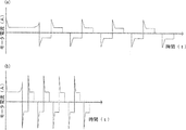
またインパクト工具1では、回転打撃力を発生させるべく、図5(a)(b)のグラフに示すように、ハンマ5を僅かに逆転させつつ正転させている。この動作は、制御回路部100によってモータ3のPWMデューティを制御することにより行われるが、例えば第二リングギヤ42Aが保持位置にある状態で最適な打撃力を発揮すべく制御回路部100でモータ3のPMWデューティを設定した状態で、第二リングギヤ42Aを非保持位置に移動させると、保持位置に第二リングギヤ42Aが配置されていた状態に比べて減速比が小さくなるため、ハンマ5を逆転させた際のハンマの回動量が大きくなる。具体的には、第二遊星歯車機構42の減速比が2.0であるため、保持位置においてハンマ5をα°逆転させる制御を行っている場合に、非保持位置で同様の制御を行うとハンマ5が2.0α°逆転することになり、好適な打撃が生じない恐れがある。よってハイ・ロー検出部27Cにより、保持位置、非保持位置を検出し、この検出結果に基づき、制御回路部100で最適なPWMデューティを設定する。
Further, in the
具体的には、図6のフローチャートに示されるように、スタートし、S01で電源を投入した後に、S02へと進み、減速切替検出を行う。具体的には、S03においてHiモードであるか否か(第二リングギヤ42Aが非保持位置にあるか否か)を判断する。
Specifically, as shown in the flowchart of FIG. 6, after starting and turning on the power in S01, the process proceeds to S02, and deceleration switching detection is performed. Specifically, in S03, it is determined whether or not the mode is the Hi mode (whether or not the
ここでS03:Noと判断された場合には、S04へと進み、演算部110において、Lowモード制御パラメータを記憶装置120から呼び出し、設定する。この設定に基づき、S05においてモータ3の正転時間T1を定め、S06においてモータ3の逆転時間T2を定め、S07においてモータ3に印加される電流閾値I1を定める。これらS05〜S07の値が定められた後にS08へ進んで、トリガ25操作によりモータ3を駆動可能な状態で待機する。
If it is determined S03: No, the process proceeds to S04, and the
次にS03:Yesと判断された場合には、S09へと進み、演算部110において、Hiモード制御パラメータを記憶装置120から呼び出し、設定する。この設定に基づき、S010においてモータ3の正転時間T1’(=T1/G1)を定め、S11においてモータ3の逆転時間T2’(=T2/G1)を定め、S12においてモータ3に印加される電流閾値I1’(=I1*G1)を定める。ここでG1は上述の第二遊星歯車機構42の減速比2.0を示している。これらS10〜S12の値が定められた後にS08へ進んで、トリガ25操作によりモータ3を駆動可能な状態で待機する。
Next, when it is determined as S03: Yes, the process proceeds to S09, and the
ハンマ5の回転角度は、モータ3におけるロータシャフト32Aの角速度が一定の場合に、回転時間に正比例し、減速比に反比例する。従って、Hiモードにおいては、Lowモードに比べて減速比が2.0倍となるが、正転時間T1’ 逆転時間T2’はそれぞれ1/2.0倍となるため、ハンマ5の回転角度は、HiモードとLowモードとにおいて等しくなる。
The rotation angle of the
またハンマ5の回転トルクは、モータ3におけるロータシャフト32Aの回転トルクが一定の場合に、減速比に正比例して大きくなる。従って、Hiモードにおいては、Lowモードに比べて回転トルクが1/2.0倍となるが、電流閾値I1’を2.0倍としてロータシャフト32Aの回転トルクが2.0倍となるため、ハンマ5の回転トルクは、HiモードとLowモードとにおいて等しくなる。
Further, the rotational torque of the
このようにT1’、T2’、I1’を設定することにより、Hiモードにおける打撃感とLowモードにおける打撃感との変化を小さくし、インパクト工具1の操作性を向上させることができる。
By setting T1 ', T2', and I1 'in this way, the change between the hit feeling in the Hi mode and the hit feeling in the Low mode can be reduced, and the operability of the
本実施の形態のインパクト工具1では、一のリングギヤである第二リングギヤ42Aを保持位置と非保持位置とに移動することにより、容易に減速比を変更することができる。またこの移動も操作部27により容易に行うことができ、容易に保持位置と非保持位置とに第二リングギヤ42Aを切り替えることができる。
In the
またモータ3はブラシレスモータであるため、その回転制御も容易であり、故に保持位置と非保持位置とにおいて、LowモードとHiモードとにモータ3の特性を切り替えて、最適な制御を行うことができる。またブラシレスモータを採用することにより、たとえばハンマ5の正転角度と逆転角度とをモータ3のホールIC34の信号と減速比とから算出し続け、ハンマ5の正転角度と逆転角度とが減速比の増加に対して反比例して減少するように、モータ3に加える正転信号及び逆転信号をフィードバック制御してもよい。このフィードバック制御によれば、より正確な打撃タイミングを得ることができ、特にモータ3の回転数が一定ではない場合に有効な制御になる。
Further, since the
また保持位置と非保持位置との検出を操作ノブ27Aの動作からハイ・ロー検出部27Cで行っているため、容易に保持位置と非保持位置とを検出することができる。なお、この検出は、直接的に第二リングギヤ42Aの位置を検出してもよい。
Further, since the holding position and the non-holding position are detected by the high /
また本実施の形態では、保持位置と非保持位置との間で移動する一のリングギヤを、モータ3を最上流としアンビル6を最下流とする動力伝達経路において、この動力伝達経路に含まれる複数の遊星歯車機構のうち、最下流に位置する第二遊星歯車機構42に設定している。第二遊星歯車機構42は、その構成にかかるギヤの回転数が、第一遊星歯車機構41の構成にかかるギヤの回転数より低いため、凸部23Aと凹部42bとの係合が容易となり、故に第二リングギヤ42Aの保持位置と非保持位置との間の移動が容易になる。
Further, in the present embodiment, one ring gear that moves between the holding position and the non-holding position is a power transmission path that includes the
また本実施の形態では、二個の遊星歯車機構を備えるインパクト工具について説明したが、これに限定されず、たとえば三個の遊星歯車機構を備えるインパクト工具にも当然適用することが可能である。また一のリングギヤでのみ減速に係る切替動作を行ったが、他のリングギヤでさらに減速に係る切替動作を行うことも可能である。 In the present embodiment, an impact tool including two planetary gear mechanisms has been described. However, the present invention is not limited to this, and can naturally be applied to an impact tool including three planetary gear mechanisms. In addition, the switching operation related to the deceleration is performed with only one ring gear, but the switching operation related to the deceleration can be performed with another ring gear.
1:インパクト工具 2:ハウジング 3:モータ 4:ギヤ機構 4A:枠体
5:ハンマ 6:アンビル 6a:穿孔 6b:装着孔 7:電池
21:主ハウジング 21A:胴体部 21B:ハンドル 22:ハンマケース
22A:軸受 23:係合部 23A:凸部 23B:スラストベアリング
24:端子部 25:トリガ 25A:スイッチ部 25B:正逆切替レバー
26:照射部 27:操作部 27A:操作ノブ 27B:係合部
27C:ハイ・ロー検出部 31:ステータ 32:ロータ 32A:ロータシャフト
32B:ファン 32C:第一ピニオンギヤ 32D:ベアリング
32E:ベアリング 33:モータ駆動回路装置 41:第一遊星歯車機構
41A:第一リングギヤ 41B:第一遊星ギヤ 41C:第一ニードルローラ
41D:第一遊星キャリア 41E:第二ピニオンギヤ 42:第二遊星歯車機構
42A:第二リングギヤ 42B:第二遊星ギヤ 42C:第二ニードルローラ
42D:第二遊星キャリア 42E:回転被支承部 42a:溝 42b:凹部
43:操作部 51A:爪部 61:先端工具装着部 62:ボール 63:操作部
64:羽根部 100:制御回路部 110:演算部 111:スイッチ操作検出回路
112:印加電圧設定回路 113:回転方向設定回路 114:電流検出回路
115:回転子位置検出回路 116:回転角度検出回路 117:減速切替検出部
119:制御信号出力回路 120:記憶装置
1: Impact tool 2: Housing 3: Motor 4:
21:
22A: Bearing 23: Engaging
24: Terminal part 25:
26: Irradiation part 27:
27C: High / Low Detection Unit 31: Stator 32:
32E: Bearing 33: Motor drive circuit device 41: First planetary gear mechanism
41A:
42A:
42D: Second
Claims (6)
該モータで回転駆動されるハンマと、
該ハンマにより回転打撃されると共に先端工具に打撃力を伝達するアンビルと、
該モータと該ハンマとの間に介在し、それぞれリングギヤを有し、該モータの回転力を該ハンマに伝達する複数の遊星歯車機構と、
該モータと該ハンマと該アンビルと該それぞれのリングギヤとを保持するハウジングと、を備え、
該それぞれのリングギヤのうち、少なくとも一のリングギヤは、該ハウジングに係合して保持される保持位置と該ハウジングに非係合で該ハウジングに対して回転可能な非保持位置との間で移動可能に構成されていることを特徴とするインパクト工具。 A motor,
A hammer driven to rotate by the motor;
An anvil which is struck by rotation with the hammer and transmits a striking force to the tip tool;
A plurality of planetary gear mechanisms interposed between the motor and the hammer, each having a ring gear, and transmitting the rotational force of the motor to the hammer;
A housing for holding the motor, the hammer, the anvil, and the respective ring gear;
Of the ring gears, at least one ring gear is movable between a holding position engaged with the housing and held and a non-holding position rotatable relative to the housing without engaging the housing. An impact tool characterized by being composed of
該一のリングギヤは該係合部と係合する被係合部を有し、
該係合部と該被係合部とは、該保持位置において係合し、該被保持位置において係合不能となるように構成されていることを特徴とする請求項1に記載のインパクト工具。 The housing has an engaging portion that engages with the one ring gear;
The one ring gear has an engaged portion that engages with the engaging portion,
2. The impact tool according to claim 1, wherein the engaging portion and the engaged portion are configured to engage at the holding position and be unable to engage at the held position. .
該操作部は、該ハウジングの外表面に露出していることを特徴とする請求項1または請求項2のいずれかに記載のインパクト工具。 An operation unit capable of operating the one ring gear between the holding position and the non-holding position;
The impact tool according to claim 1, wherein the operation portion is exposed on an outer surface of the housing.
該モータの回転制御を行う制御部を更に備え、
該制御部は、該一のリングギヤが該保持位置と該非保持位置とのそれぞれの位置において、該回転制御を変更可能に構成されていることを特徴とする請求項1乃至請求項4のいずれかに記載のインパクト工具。 The motor is a brushless motor;
A control unit for controlling the rotation of the motor;
5. The control unit according to claim 1, wherein the one ring gear is configured to be able to change the rotation control at each of the holding position and the non-holding position. Impact tool as described in
該制御部は該検出装置の検出結果に基づき該回転制御を行うことを特徴とする請求項5に記載のインパクト工具。 A detection device for detecting a position of the one ring gear in the holding position and the non-holding position;
The impact tool according to claim 5, wherein the control unit performs the rotation control based on a detection result of the detection device.
Priority Applications (5)
| Application Number | Priority Date | Filing Date | Title |
|---|---|---|---|
| JP2011238172A JP2013094864A (en) | 2011-10-31 | 2011-10-31 | Impact tool |
| PCT/JP2012/005493 WO2013065222A1 (en) | 2011-10-31 | 2012-08-30 | Impact tool |
| CN201280032258.9A CN103648723A (en) | 2011-10-31 | 2012-08-30 | Impact tool |
| DE112012004552.1T DE112012004552T5 (en) | 2011-10-31 | 2012-08-30 | impact tool |
| US14/129,924 US20140124229A1 (en) | 2011-10-31 | 2012-08-30 | Impact tool |
Applications Claiming Priority (1)
| Application Number | Priority Date | Filing Date | Title |
|---|---|---|---|
| JP2011238172A JP2013094864A (en) | 2011-10-31 | 2011-10-31 | Impact tool |
Publications (1)
| Publication Number | Publication Date |
|---|---|
| JP2013094864A true JP2013094864A (en) | 2013-05-20 |
Family
ID=46934638
Family Applications (1)
| Application Number | Title | Priority Date | Filing Date |
|---|---|---|---|
| JP2011238172A Pending JP2013094864A (en) | 2011-10-31 | 2011-10-31 | Impact tool |
Country Status (5)
| Country | Link |
|---|---|
| US (1) | US20140124229A1 (en) |
| JP (1) | JP2013094864A (en) |
| CN (1) | CN103648723A (en) |
| DE (1) | DE112012004552T5 (en) |
| WO (1) | WO2013065222A1 (en) |
Cited By (5)
| Publication number | Priority date | Publication date | Assignee | Title |
|---|---|---|---|---|
| JP2017205834A (en) * | 2016-05-18 | 2017-11-24 | 株式会社マキタ | Electric work machine |
| WO2018062609A1 (en) * | 2016-09-28 | 2018-04-05 | 계양전기 주식회사 | Tool assembly for electric power tool and electric power tool comprising same |
| JP2021024041A (en) * | 2019-08-06 | 2021-02-22 | 株式会社マキタ | Rotary tool and driver drill |
| US11673240B2 (en) | 2019-08-06 | 2023-06-13 | Makita Corporation | Driver-drill |
| US11890730B2 (en) | 2019-01-10 | 2024-02-06 | Makita Corporation | Power tool |
Families Citing this family (15)
| Publication number | Priority date | Publication date | Assignee | Title |
|---|---|---|---|---|
| US9114512B2 (en) | 2013-05-15 | 2015-08-25 | Snap-On Incorporated | Process and apparatus for locating light emitting diode in a hand tool head assembly |
| JP6245367B2 (en) * | 2014-06-30 | 2017-12-13 | 日立工機株式会社 | Impact tool |
| CN107355528A (en) * | 2016-05-10 | 2017-11-17 | 德昌电机(深圳)有限公司 | A kind of electric tool of drive device and the application drive device |
| DE102016214015B4 (en) * | 2016-07-29 | 2022-03-31 | Schaeffler Technologies AG & Co. KG | Planetary differential device and method of manufacturing the planetary differential device |
| KR101895334B1 (en) * | 2016-12-23 | 2018-09-06 | 계양전기 주식회사 | Apparatus for transmission in electric power tool |
| AU2019221782A1 (en) * | 2018-02-19 | 2020-10-08 | Milwaukee Electric Tool Corporation | Impact tool |
| US11597061B2 (en) * | 2018-12-10 | 2023-03-07 | Milwaukee Electric Tool Corporation | High torque impact tool |
| WO2020132587A1 (en) * | 2018-12-21 | 2020-06-25 | Milwaukee Electric Tool Corporation | High torque impact tool |
| CN111645036B (en) * | 2019-03-04 | 2023-09-29 | 株式会社牧田 | Work tool |
| CN211805940U (en) | 2019-09-20 | 2020-10-30 | 米沃奇电动工具公司 | Impact tool and hammer head |
| JP7320419B2 (en) | 2019-09-27 | 2023-08-03 | 株式会社マキタ | rotary impact tool |
| JP7386027B2 (en) * | 2019-09-27 | 2023-11-24 | 株式会社マキタ | rotary impact tool |
| USD948978S1 (en) | 2020-03-17 | 2022-04-19 | Milwaukee Electric Tool Corporation | Rotary impact wrench |
| JP2022158636A (en) * | 2021-04-02 | 2022-10-17 | 株式会社マキタ | Electric power tool and impact tool |
| JP2023167146A (en) * | 2022-05-11 | 2023-11-24 | 株式会社マキタ | Power tool |
Family Cites Families (38)
| Publication number | Priority date | Publication date | Assignee | Title |
|---|---|---|---|---|
| GB1404063A (en) * | 1972-05-24 | 1975-08-28 | Desoutter Brothers Ltd | Power driven rotary tool |
| JP3323686B2 (en) * | 1995-01-10 | 2002-09-09 | アスモ株式会社 | Moving object position detection device |
| US5550416A (en) * | 1995-02-09 | 1996-08-27 | Fanchang; We C. | Control mechanism of revolving speed of an electric tool |
| US5998727A (en) * | 1997-12-11 | 1999-12-07 | Roland Kabushiki Kaisha | Musical apparatus using multiple light beams to control musical tone signals |
| US6142242A (en) * | 1999-02-15 | 2000-11-07 | Makita Corporation | Percussion driver drill, and a changeover mechanism for changing over a plurality of operating modes of an apparatus |
| DE29904051U1 (en) * | 1999-03-05 | 1999-06-17 | Chung Lee Hsin Chih | Switching device for a reduction gear |
| JP3911905B2 (en) * | 1999-04-30 | 2007-05-09 | 松下電工株式会社 | Impact rotary tool |
| JP3456949B2 (en) * | 2000-06-19 | 2003-10-14 | 株式会社エスティック | Method and apparatus for controlling screw tightening device |
| US6733414B2 (en) * | 2001-01-12 | 2004-05-11 | Milwaukee Electric Tool Corporation | Gear assembly for a power tool |
| US6676557B2 (en) * | 2001-01-23 | 2004-01-13 | Black & Decker Inc. | First stage clutch |
| US6431289B1 (en) * | 2001-01-23 | 2002-08-13 | Black & Decker Inc. | Multi-speed power tool transmission |
| US7101300B2 (en) * | 2001-01-23 | 2006-09-05 | Black & Decker Inc. | Multispeed power tool transmission |
| DE10302114B4 (en) * | 2002-01-25 | 2009-02-26 | Black & Decker Inc., Newark | Hand-held, power-driven tool with simplified assembly of clutch mechanism and gearbox |
| BR0307083A (en) * | 2002-01-25 | 2004-12-28 | Black & Decker Inc | Electric Drill / Screwdriver |
| JP3740694B2 (en) * | 2002-02-22 | 2006-02-01 | 日立工機株式会社 | Electric tool |
| US6729414B2 (en) * | 2002-07-16 | 2004-05-04 | Black & Decker Inc. | Cordless drill with metal housing |
| US7044882B2 (en) * | 2003-04-03 | 2006-05-16 | Atlas Copco Electric Tools Gmbh | Switchable gearbox of a handheld power tool |
| JP4405900B2 (en) * | 2004-03-10 | 2010-01-27 | 株式会社マキタ | Impact driver |
| US7308948B2 (en) * | 2004-10-28 | 2007-12-18 | Makita Corporation | Electric power tool |
| JP4487836B2 (en) * | 2005-04-20 | 2010-06-23 | 日立工機株式会社 | Electric tool |
| US20060237205A1 (en) * | 2005-04-21 | 2006-10-26 | Eastway Fair Company Limited | Mode selector mechanism for an impact driver |
| JP4400519B2 (en) * | 2005-06-30 | 2010-01-20 | パナソニック電工株式会社 | Impact rotary tool |
| US7168503B1 (en) * | 2006-01-03 | 2007-01-30 | Mobiletron Electronics Co., Ltd. | Power hand tool |
| US7980324B2 (en) * | 2006-02-03 | 2011-07-19 | Black & Decker Inc. | Housing and gearbox for drill or driver |
| EP1970165A1 (en) * | 2007-03-12 | 2008-09-17 | Robert Bosch Gmbh | A rotary power tool operable in a first speed mode and a second speed mode |
| EP2030710B1 (en) * | 2007-08-29 | 2014-04-23 | Positec Power Tools (Suzhou) Co., Ltd. | Power tool and control system for a power tool |
| JP5360344B2 (en) * | 2007-09-21 | 2013-12-04 | 日立工機株式会社 | Electric tool |
| CN101612725B (en) * | 2008-06-26 | 2013-07-31 | 苏州宝时得电动工具有限公司 | Power tool |
| DE102008042354A1 (en) * | 2008-09-25 | 2010-04-01 | Robert Bosch Gmbh | Hand tool with a switchable gearbox |
| US8251158B2 (en) * | 2008-11-08 | 2012-08-28 | Black & Decker Inc. | Multi-speed power tool transmission with alternative ring gear configuration |
| CN101786179B (en) * | 2009-01-23 | 2012-01-04 | 车王电子(宁波)有限公司 | Electric tool |
| JP4674640B2 (en) * | 2009-01-27 | 2011-04-20 | パナソニック電工株式会社 | Impact rotary tool |
| JP5440766B2 (en) | 2009-07-29 | 2014-03-12 | 日立工機株式会社 | Impact tools |
| JP5126347B2 (en) * | 2009-11-30 | 2013-01-23 | マックス株式会社 | Rotating tool |
| US8584770B2 (en) * | 2010-03-23 | 2013-11-19 | Black & Decker Inc. | Spindle bearing arrangement for a power tool |
| JP5075233B2 (en) * | 2010-07-29 | 2012-11-21 | パナソニックEsパワーツール株式会社 | Electric tool |
| JP5686236B2 (en) * | 2010-07-30 | 2015-03-18 | 日立工機株式会社 | Electric tools and electric tools for screw tightening |
| JP5468570B2 (en) * | 2011-06-17 | 2014-04-09 | 株式会社マキタ | Impact tool |
-
2011
- 2011-10-31 JP JP2011238172A patent/JP2013094864A/en active Pending
-
2012
- 2012-08-30 CN CN201280032258.9A patent/CN103648723A/en active Pending
- 2012-08-30 WO PCT/JP2012/005493 patent/WO2013065222A1/en active Application Filing
- 2012-08-30 US US14/129,924 patent/US20140124229A1/en not_active Abandoned
- 2012-08-30 DE DE112012004552.1T patent/DE112012004552T5/en not_active Withdrawn
Cited By (7)
| Publication number | Priority date | Publication date | Assignee | Title |
|---|---|---|---|---|
| JP2017205834A (en) * | 2016-05-18 | 2017-11-24 | 株式会社マキタ | Electric work machine |
| WO2018062609A1 (en) * | 2016-09-28 | 2018-04-05 | 계양전기 주식회사 | Tool assembly for electric power tool and electric power tool comprising same |
| US11890730B2 (en) | 2019-01-10 | 2024-02-06 | Makita Corporation | Power tool |
| JP2021024041A (en) * | 2019-08-06 | 2021-02-22 | 株式会社マキタ | Rotary tool and driver drill |
| US11673240B2 (en) | 2019-08-06 | 2023-06-13 | Makita Corporation | Driver-drill |
| JP7324649B2 (en) | 2019-08-06 | 2023-08-10 | 株式会社マキタ | rotary tools and driver drills |
| US11911881B2 (en) | 2019-08-06 | 2024-02-27 | Makita Corporation | Driver-drill |
Also Published As
| Publication number | Publication date |
|---|---|
| DE112012004552T5 (en) | 2014-08-07 |
| CN103648723A (en) | 2014-03-19 |
| US20140124229A1 (en) | 2014-05-08 |
| WO2013065222A1 (en) | 2013-05-10 |
Similar Documents
| Publication | Publication Date | Title |
|---|---|---|
| JP2013094864A (en) | Impact tool | |
| WO2013136711A2 (en) | Impact tool | |
| US10040178B2 (en) | Power tool and rotary impact tool | |
| JP5769385B2 (en) | Electric tool | |
| US11780061B2 (en) | Impact tool | |
| US9950417B2 (en) | Power tool | |
| JP5483086B2 (en) | Impact tools | |
| US20140158390A1 (en) | Electric tool | |
| US20120234566A1 (en) | Impact tool | |
| JP2009285787A (en) | Electric power tool | |
| WO2017159201A1 (en) | Electrically driven tool | |
| JP2011255483A (en) | Electric tool and power tool | |
| JP5725354B2 (en) | Electric tool | |
| JP2014104541A (en) | Hand-held electric tool | |
| JP5674027B2 (en) | Tightening tool | |
| JP5534328B2 (en) | Electric tool | |
| JP2012139767A (en) | Driving tool | |
| US20230182271A1 (en) | Impact tool | |
| JP5720943B2 (en) | Impact tools | |
| JP6863415B2 (en) | Electric tool | |
| JP5561535B2 (en) | Electric tool | |
| JP2022162873A (en) | Multi-axis fastener | |
| JP2020182978A (en) | Screw fastening tool |
Legal Events
| Date | Code | Title | Description |
|---|---|---|---|
| A621 | Written request for application examination |
Free format text: JAPANESE INTERMEDIATE CODE: A621 Effective date: 20140926 |
|
| A131 | Notification of reasons for refusal |
Free format text: JAPANESE INTERMEDIATE CODE: A131 Effective date: 20150511 |
|
| A02 | Decision of refusal |
Free format text: JAPANESE INTERMEDIATE CODE: A02 Effective date: 20151005 |