WO2010050083A1 - 保護継電装置とその送信レベル制御方法 - Google Patents
保護継電装置とその送信レベル制御方法 Download PDFInfo
- Publication number
- WO2010050083A1 WO2010050083A1 PCT/JP2009/001340 JP2009001340W WO2010050083A1 WO 2010050083 A1 WO2010050083 A1 WO 2010050083A1 JP 2009001340 W JP2009001340 W JP 2009001340W WO 2010050083 A1 WO2010050083 A1 WO 2010050083A1
- Authority
- WO
- WIPO (PCT)
- Prior art keywords
- transmission
- level
- reception
- relay device
- data
- Prior art date
- Legal status (The legal status is an assumption and is not a legal conclusion. Google has not performed a legal analysis and makes no representation as to the accuracy of the status listed.)
- Ceased
Links
Images

Classifications
-
- H—ELECTRICITY
- H02—GENERATION; CONVERSION OR DISTRIBUTION OF ELECTRIC POWER
- H02H—EMERGENCY PROTECTIVE CIRCUIT ARRANGEMENTS
- H02H3/00—Emergency protective circuit arrangements for automatic disconnection directly responsive to an undesired change from normal electric working condition with or without subsequent reconnection ; integrated protection
- H02H3/26—Emergency protective circuit arrangements for automatic disconnection directly responsive to an undesired change from normal electric working condition with or without subsequent reconnection ; integrated protection responsive to difference between voltages or between currents; responsive to phase angle between voltages or between currents
- H02H3/28—Emergency protective circuit arrangements for automatic disconnection directly responsive to an undesired change from normal electric working condition with or without subsequent reconnection ; integrated protection responsive to difference between voltages or between currents; responsive to phase angle between voltages or between currents involving comparison of the voltage or current values at two spaced portions of a single system, e.g. at opposite ends of one line, at input and output of apparatus
- H02H3/30—Emergency protective circuit arrangements for automatic disconnection directly responsive to an undesired change from normal electric working condition with or without subsequent reconnection ; integrated protection responsive to difference between voltages or between currents; responsive to phase angle between voltages or between currents involving comparison of the voltage or current values at two spaced portions of a single system, e.g. at opposite ends of one line, at input and output of apparatus using pilot wires or other signalling channel
-
- H—ELECTRICITY
- H02—GENERATION; CONVERSION OR DISTRIBUTION OF ELECTRIC POWER
- H02H—EMERGENCY PROTECTIVE CIRCUIT ARRANGEMENTS
- H02H3/00—Emergency protective circuit arrangements for automatic disconnection directly responsive to an undesired change from normal electric working condition with or without subsequent reconnection ; integrated protection
- H02H3/02—Details
-
- H—ELECTRICITY
- H02—GENERATION; CONVERSION OR DISTRIBUTION OF ELECTRIC POWER
- H02H—EMERGENCY PROTECTIVE CIRCUIT ARRANGEMENTS
- H02H3/00—Emergency protective circuit arrangements for automatic disconnection directly responsive to an undesired change from normal electric working condition with or without subsequent reconnection ; integrated protection
- H02H3/26—Emergency protective circuit arrangements for automatic disconnection directly responsive to an undesired change from normal electric working condition with or without subsequent reconnection ; integrated protection responsive to difference between voltages or between currents; responsive to phase angle between voltages or between currents
- H02H3/28—Emergency protective circuit arrangements for automatic disconnection directly responsive to an undesired change from normal electric working condition with or without subsequent reconnection ; integrated protection responsive to difference between voltages or between currents; responsive to phase angle between voltages or between currents involving comparison of the voltage or current values at two spaced portions of a single system, e.g. at opposite ends of one line, at input and output of apparatus
-
- H—ELECTRICITY
- H04—ELECTRIC COMMUNICATION TECHNIQUE
- H04B—TRANSMISSION
- H04B3/00—Line transmission systems
- H04B3/02—Details
- H04B3/30—Reducing interference caused by unbalanced currents in a normally balanced line
Definitions
- the present invention relates to a protection relay device that performs an accident determination inside and outside a protection section by exchanging data between a plurality of protection relay devices using transmission.
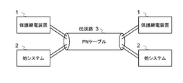
- the transmission line 3 used by the protective relay device 1 and the other system 2 is another core wire in the display line cable. Since the plurality of core wires in the display line cable are in a very close positional relationship with each other, the transmission relay 3 used by the protective relay device 1 and the other system 2 is substantially in a very close positional relationship with each other. . In such a case, it is necessary to consider, for example, adjusting the transmission level so that the transmission of the protective relay device 1 does not interfere with the transmission of another system 2 on the transmission line and cause a communication failure.
- Patent Document 2 As an example of adjusting the transmission level in a general transmission system, there are technologies described in Patent Document 2 and Patent Document 3.
- JP 2004-88920 A Japanese Patent Laid-Open No. 2005-341022 JP-A-5-30031
- the protection relay device 1 and another system 2 such as a monitoring control system are configured by using the core wire in the same display line cable 3, the influence of the transmission of the protection relay device 1. Therefore, it is necessary to reduce the transmission level of transmission of the protective relay device 1 to some extent so that communication failure does not occur in the other system 2. However, since the conditions change depending on the distance of the display line, etc., the transmission level cannot be fixed in advance.
- the method disclosed in Patent Document 2 multiplexes a transmission signal with a specific code and transmits it, calculates the attenuation from the transmission delay and line length of the signal, and adjusts the transmission level.
- the method of Patent Document 3 is a method of increasing the transmission level and increasing the reception level margin when the duty value on the receiving side is low in optical communication. Each method is intended to ensure the transmission quality of its own system, and is not intended to prevent the influence on other systems using a display line or the like.
- the present invention has been proposed in order to solve the above-described problems of the prior art, and its purpose is to transmit data transmission so as not to affect other systems using adjacent transmission paths.
- a protection relay device capable of appropriately adjusting a level and a transmission level control method thereof are provided.
- the first aspect of the protection relay device is to perform data transmission by a transmission / reception circuit through a transmission relay and a protection relay device at opposite ends across the protection target section, and an accident inside and outside the protection target section.
- the protection relay device for determining the data level immediately after establishment of data transmission through the transmission path between the reception level detection unit for detecting the reception level of the data received by the transmission / reception circuit and the protection relay device at the opposite end
- the transmission level of data transmission by the transmission / reception circuit A transmission level control unit that performs transmission level lowering control for reducing the transmission level.
- the protection relay device focuses on the fact that the transmission level and the reception level immediately after establishment of data transmission between the protection relay devices at both ends of the protection target section are generally the same between the devices. As a result, it is recalled. In other words, the conditions of the transmission line between the protective relay devices at both ends are generally the same in both directions. In particular, when a display line is used, transmission information and reception information are alternated on the same transmission line. Is transmitted. Therefore, the transmission level and the reception level for a certain period of time immediately after the establishment of data transmission between the protective relay devices at both ends are the same between the protective relay devices at both ends.
- the reception level for a certain time immediately after the establishment of data transmission between the protection relay devices at both ends is used in each protection relay device,
- the transmission level control unit can perform control to lower the transmission level.
- the transmission levels of the protective relay devices at both ends can be reduced almost simultaneously, and the influence on other systems (such as a remote monitoring control system) using adjacent transmission paths can be eliminated.
- the technique of the first mode is, in other words, from the viewpoint of data to be used, instead of using the actual data of the reception level at the counterpart device of the data transmitted from the own device, the reception level of the data received from the counterpart device is set. This is a technique used as substitute data. By using such substitute data, the timing for performing the transmission level control is limited to a certain time immediately after the transmission is established, that is, the time when the transmission level and the reception level are the same. .
- the protective relay device for determining the data the reception level detection unit for detecting the reception level of the data received by the transmission / reception circuit, and the data transmitted by the transmission / reception circuit include the data so that the received reception level of the own device is detected.
- the protection relay device is different from the first aspect in that the reception level is included in the data to be transmitted / received.
- the protection relay device according to the second aspect receives data including the reception level of the opposite protection relay device, so that each protection relay device is the counterpart device of the data transmitted by itself.
- the reception level at can be grasped. Therefore, according to the actual reception level at the counterpart device, the transmission level from the own device can be appropriately adjusted so that the level received by the counterpart device becomes a predetermined level.
- the transmission level control is different from the first mode in which the reception level of the data received from the counterpart device is used as substitute data. It is not necessary to limit the timing for performing the transmission to a certain time immediately after the transmission is established. Therefore, more appropriate transmission level control can be performed.
- the transmission level control method of the protective relay device of the present invention grasps the characteristics of the protective relay device from the viewpoint of the method.
- a protection relay device and a transmission level control method thereof capable of appropriately and automatically adjusting the transmission level of data transmission so as not to affect other systems using adjacent transmission paths. Can do.
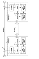
- FIG. 1 is a block diagram showing a configuration of a protective relay device according to a first embodiment to which the present invention is applied.
- protection relay devices 1 having the same configuration are installed at both ends of a transmission line 4 that is a protection target section.
- the protective relay device 1 includes an analog / digital (A / D) conversion unit 11, a calculation unit 12, a transmission / reception circuit 13, a reception level detection unit 14, and a transmission level control unit 15.
- a / D analog / digital
- the operation of the protective relay device 1 is as follows.
- the analog / digital (A / D) conversion unit 11 takes in the current of the transmission line 4 through the current transformer (CT) 5, converts the analog data of the current into digital data, and introduces it into the calculation unit 12. Is done.
- the calculation unit 12 supplies the current data at its own end to the transmission / reception circuit 13 and also captures the current data at the opposite end received by the transmission / reception circuit 13 to execute various protection calculations such as a current differential calculation.
- the transmission / reception circuit 13 transmits the current data at its own end as transmission data to the protection relay device 1 at the opposite end via the transmission path 3.
- Such handling of current data by the A / D conversion unit 11, the calculation unit 12, and the transmission / reception circuit 13 is a basic operation in the protective relay device.
- the following characteristic operations are performed.
- the reception level of the transmission data from the opposite end received by the transmission / reception circuit 13 is detected by the reception level detection unit 14, and the detected reception level is given to the transmission level control unit 15.
- the transmission level control unit 15 performs transmission level lowering control based on the difference between the detected reception level and a predetermined reception level set in advance.
- the transmission level lowering control by the transmission level control unit 15 in order to simultaneously reduce the transmission level by the protective relay device 1 at both ends, it is set in advance after data transmission with the protective relay device 1 at the opposite end is established.
- the transmission level reduction is adjusted using the detected reception level detected within the predetermined time t1.
- the detected reception level used for comparison with the predetermined reception level is within a certain time t1 after the establishment of data transmission, and adjustment of the decrease in the transmission level when the detected reception level is higher than the predetermined level is performed by data transmission. It is carried out after a lapse of a fixed time t1 after establishment.
- the specific level of specific reception is within a range (actual measurement range or prediction range) that does not substantially affect the specific transmission path 3 according to the positional relationship with the transmission path of another system, and It is appropriately selected within a range (measurement range or prediction range) in which the performance of the protective relay device 1 is not deteriorated.
- the specific fixed time t1 is set according to the time (actual measurement time or predicted time) in which the transmission level and the reception level after the establishment of data transmission are the same between apparatuses.
- the actual measurement value or the predicted value used for setting the predetermined level of reception or the predetermined time t1 can be obtained by a statistical method using actual measurement data or past data in the field.
- the transmission level control unit 15 when the reception level of a certain time immediately after the establishment of data transmission between the protection relay devices 1 at both ends is used in the mutual protection relay devices and the value is higher than a predetermined level, the transmission level control unit 15 Thus, it is possible to control to reduce the transmission level. As a result, the transmission levels of the protective relay devices 1 at both ends can be lowered almost simultaneously, and the influence on other systems (such as a remote monitoring control system) using adjacent transmission paths can be eliminated. Therefore, it is possible to provide a protective relay device and a transmission level control method thereof that can appropriately and automatically adjust the transmission level of data transmission so as not to affect other systems that use adjacent transmission paths.
- the technique of the first embodiment is different from the viewpoint of data to be used.
- the reception level of the data received from the counterpart device Is used as substitute data.
- the timing for performing the transmission level control is limited to a certain time immediately after the transmission is established, that is, the time when the transmission level and the reception level are the same. .
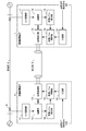
- FIG. 2 is a block diagram showing a configuration of a protective relay device according to a second embodiment to which the present invention is applied.
- the protection relay device 1 of the present embodiment includes a both-end reception level detection unit 21 instead of the reception level detection unit 14 and the transmission level control unit 15 in the protection relay device 1 shown in FIG. 1. And a transmission data / transmission level control unit 22.
- the other configuration is the same as that of the protective relay device 1 shown in FIG.
- the basic operations by the A / D conversion unit 11, the arithmetic unit 12, and the transmission / reception circuit 13 are the same as those of the protective relay device 1 shown in FIG.
- the following characteristic operation is performed.
- the reception level of transmission data from the opposite end received by the transmission / reception circuit 13 is detected by the both-end reception level detection unit 21, and the detected reception level is given to the transmission data / transmission level control unit 22.
- the transmission data / transmission level control unit 22 adds the detected reception level to the transmission data transmitted from the transmission / reception circuit 13.
- the transmission / reception circuit 13 transmits data including the reception level at its own end in addition to the current data at its own end to the protection relay device 1 at the opposite end as transmission data.
- the transmission / reception circuit 13 at the reception destination receives the transmission data from the opposite end together with the current data at the opposite end from the own end.
- the reception level at the opposite end of the transmission data is acquired.
- the reception level at the opposite end is detected by the both-end reception level detection unit 21 and given to the transmission data / transmission level control unit 22.
- the transmission data / transmission level control unit 22 performs transmission level reduction control based on the difference between the detected reception level at the opposite end and a predetermined reception level set in advance.
- the protection relay device 1 since the protection relay device 1 receives data including the reception level of the opposite protection relay device 1, each protection relay device 1 receives the reception level of the data transmitted by itself in the counterpart device. Can be grasped. Therefore, according to the actual reception level at the counterpart device, the transmission level from the own device can be appropriately adjusted so that the level received by the counterpart device becomes a predetermined level.
- the transmission is performed. There is no need to limit the timing for performing the level control to a certain time immediately after the transmission is established. Therefore, more appropriate transmission level control can be performed.
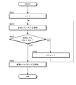
- FIG. 3 is a flowchart illustrating an example of a technique for obtaining a transmission level adjustment value using a plurality of setting values.
- m setting values S (n) as shown below are set in advance as transmission levels.
- S (n) (S1, S2, S3,..., Sm)
- the magnitude relationship between the m set values is gradually reduced as shown below. S1>S2>S3>,...> Sm
- the transmission level S (n) is selected and detected while incrementing n by 1.
- the reception level Rn is compared with the target reception level Rm.
- Increments n by one S304) and switches the transmission level to a lower setting value (S302). This switching is sequentially repeated, and when the detected reception level Rn becomes smaller than the target reception level Rm, the setting value is switched to the previous set value S (n ⁇ 1) that is one step higher than this time (S305), and the process ends.
- the step-by-step switching of the transmission level can be performed by simple selection of a preset setting value, and can be realized with a simple circuit.
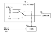
- FIG. 4 is a block diagram showing a configuration of a protective relay device according to a third embodiment to which the present invention is applied.
- the protective relay device 1 of the present embodiment is obtained by adding a contact input (DI) circuit 31 to the configuration of the protective relay device 1 shown in FIG. 1.
- DI contact input
- the protective relay device 1 of the present embodiment basic operations by the A / D conversion unit 11, the arithmetic unit 12, and the transmission / reception circuit 13, and characteristic operations by the reception level detection unit 14 and the transmission level control unit 15 Is the same as the protective relay device 1 shown in FIG. In the protective relay device 1 of the present embodiment, the following characteristic operation is further performed by the DI circuit 31.
- the transmission level control unit 15 can perform the transmission level lowering control, and the execution condition contact signal 101 is not input. Prohibits execution of transmission level lowering control by the transmission level control unit 15.
- the execution condition contact signal 101 for example, a communication failure alarm contact of an external remote monitoring control system using a transmission line adjacent to the transmission line 3, or a switch of a transmission level lowering control command by a human system It is conceivable to connect the contacts such as, and input the signal.
- Transmission level lowering control by performing transmission level lowering control on condition that the execution condition contact signal 101 is input, by inputting the execution condition contact signal 101 from any other external system or protection relay device as needed, Transmission level lowering control can be performed at an arbitrary timing.
- the transmission level lowering control can be further repeated.
- the transmission level lowering control can be performed only when the transmission level is lowered, unnecessary transmission level lowering control can be avoided. That is, it is possible to suppress a decrease in transmission level due to transmission level switching to a level at which other systems using adjacent transmission paths are not affected.
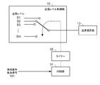
- FIG. 5 shows an image of a technique for causing the transmission level control unit 15 to perform stepwise transmission level switching by a signal from the DI circuit 31 (indicated by a broken line arrow) when the condition execution contact signal 101 is input.
- FIG. 5 shows an image of a technique for causing the transmission level control unit 15 to perform stepwise transmission level switching by a signal from the DI circuit 31 (indicated by a broken line arrow) when the condition execution contact signal 101 is input.
- FIG. 6 shows a timer 32 for confirming a predetermined time t2 when the DI circuit 31 inputs a signal from a contact that continuously closes during an alarm occurrence by the DI circuit 31 in the configuration of FIG. It is a thing.
- the transmission level is switched by one step to lower the transmission level by one step, and the execution condition contact When the input of the signal 101 is continued, the transmission level is switched by one step every fixed time t2.
- the fixed time t2 set in this case is a value obtained by performing a one-step transmission level lowering control and providing a margin for the time required to return from the alarm to the normal state when the reception level decreases. There is a need to.
- the transmission level is lowered more than necessary by switching the transmission level in one step every fixed time only during the alarm period. Can be prevented.
- the both-end reception level detection unit and the transmission data / transmission level control unit in the embodiment shown in FIG. 2 may be made independent for each function. That is, the both-end reception level detection unit can be separated and independent as individual reception level detection units for detecting the reception levels of the own end and the opposite end, and the transmission data / transmission level control unit It is also possible to separate the transmission data control unit for adding the reception level and the transmission level control unit for controlling the transmission level. Conversely, the reception level detection unit and the transmission level control unit can be integrated as a single functional unit.
Landscapes
- Engineering & Computer Science (AREA)
- Computer Networks & Wireless Communication (AREA)
- Signal Processing (AREA)
- Power Engineering (AREA)
- Emergency Protection Circuit Devices (AREA)
- Cable Transmission Systems, Equalization Of Radio And Reduction Of Echo (AREA)
Abstract
Description
図1は、本発明を適用した第1の実施形態に係る保護継電装置の構成を示すブロック図である。図1に示すように、保護対象区間である送電線4の両端に、同一の構成を有する保護継電装置1がそれぞれ設置されている。保護継電装置1は、アナログ/ディジタル(A/D)変換部11、演算部12、送受信回路13、受信レベル検出部14、送信レベル制御部15を備えている。この保護継電装置1の動作は次の通りである。
図2は、本発明を適用した第2の実施形態に係る保護継電装置の構成を示すブロック図である。図2に示すように、本実施形態の保護継電装置1は、図1に示した保護継電装置1における受信レベル検出部14、送信レベル制御部15の代わりに、両端受信レベル検出部21と、送信データ/送信レベル制御部22を備えている。なお、他の構成は図1に示した保護継電装置1と同様である。
図1、図2に示した保護継電装置1において、送信レベル制御部15または送信データ/送信レベル制御部22による具体的な送信レベル調整値の決定手法としては、例えば、検出した受信レベルと所定レベルとのレベル比率を用いる手法と、複数の設定値を用いる手法が考えられる。以下には、これらの手法について順次説明する。
検出した受信レベルをRn、予め設定された受信の所定レベル(目標値)をRm、レベル低下調整前の送信レベルをSn、調整後の送信レベルをSmとした場合に、Smを次の式(1)に示す値とする。
Sm=Sn×Rm/Rn (1)
新たな送信レベルをこの式(1)で求められるSmとすることにより、送信レベル制御を一度実施するだけで、相手装置での受信レベルを目標値であるRmに近づけることが可能となる。
図3は、複数の設定値を用いて送信レベル調整値を求める手法の一例を示すフローチャートである。この手法では、送信レベルとして、次に示すようなm個の設定値S(n)を予め設定している。
S(n)=(S1,S2,S3,…,Sm)
ここで、m個の設定値の大小関係は、次に示すように、段階的に小さくなっている。
S1>S2>S3>,…,>Sm
図4は、本発明を適用した第3の実施形態に係る保護継電装置の構成を示すブロック図である。図4に示すように、本実施形態の保護継電装置1は、図1に示した保護継電装置1の構成に、接点入力(DI:digital input)回路31を追加したものである。なお、他の構成は図1に示した保護継電装置1と同様である。
図4に示した保護継電装置1において、送信レベルとして、m個の設定値(S1,S2,S3,…,Sm)を予め設定しておき、実施条件接点信号101の入力時に、図3に示すような段階的な送信レベル切換を行うことも考えられる。
なお、本発明は、前述した実施形態に限定されるものではなく、本発明の範囲内で他にも多種多様な変形例が実施可能である。すなわち、図面に示した装置構成は本発明の実現に必要な最小限の機能構成を示す一例にすぎず、具体的なシステム構成やハードウェア構成およびソフトウェア構成は適宜選択可能である。
3…伝送路
4…送電線
5…変流器(CT)
11…A/D変換部
12…演算部
13…送受信回路
14…受信レベル検出部
15…送信レベル制御部
21…両端受信レベル検出部
22…送信データ/送信レベル制御部
31…接点入力(DI)回路
32…タイマー
Claims (8)
- 保護対象区間を挟んで対向する対向端の保護継電装置と伝送路を通じて送受信回路によりデータ伝送を実施し、当該保護対象区間内外の事故を判定する保護継電装置において、
前記送受信回路により受信したデータの受信レベルを検出する受信レベル検出部と、
前記対向端の保護継電装置との前記伝送路を通じたデータ伝送が確立した直後の、予め設定された一定時間内に検出された受信レベルを、予め設定された所定レベルと比較して、一定時間内の受信レベルが所定レベルより大きい場合に、前記送受信回路によるデータ伝送の送信レベルを低下させる送信レベル低下制御を行う送信レベル制御部
を有することを特徴とする保護継電装置。 - 保護対象区間を挟んで対向する対向端の保護継電装置と伝送路を通じて送受信回路によりデータ伝送を実施し、当該保護対象区間内外の事故を判定する保護継電装置において、
前記送受信回路により受信したデータの受信レベルを検出する受信レベル検出部と、
前記送受信回路により送信するデータが、検出した自装置の受信レベルを含むようにデータを制御する送信データ制御部と、
前記送受信回路により受信したデータ中に含まれる前記対向端の保護継電装置の受信レベルを検出する対向端受信レベル検出部と、
検出した対向端の受信レベルが予め設定された所定レベルより大きい場合に、前記送受信回路によるデータ伝送の送信レベルを低下させる送信レベル低下制御を行う送信レベル制御部
を有することを特徴とする保護継電装置。 - 前記送信レベル低下制御は、前記検出した受信レベルをRn、前記所定レベルをRmとした場合に、送信レベルをRm/Rn倍とする調整を行うものである
ことを特徴とする、請求項1または請求項2に記載の保護継電装置。 - 前記送信レベル低下制御は、前記送信レベルとして予め段階的に設定された複数の設定値を使用し、前記検出した受信レベルが前記所定レベルを下回らない範囲で最も小さくなるように、送信レベルを前記複数の設定値の中から選択するものである
ことを特徴とする、請求項1または請求項2に記載の保護継電装置。 - 予め設定された実施条件信号を入力した場合にのみ、前記送信レベル制御部による前記送信レベル低下制御の実施を可能にする実施条件信号入力部
を有することを特徴とする、請求項1または請求項2に記載の保護継電装置。 - 前記送信レベル低下制御は、前記送信レベルの設定値として予め段階的に設定された複数の設定値を使用し、前記実施条件信号入力部により前記実施条件信号が入力された場合に、送信レベルを前記複数の設定値の間で切り換えるものである
ことを特徴とする、請求項1または請求項2に記載の保護継電装置。 - 保護対象区間を挟んで対向する対向端の保護継電装置と伝送路を通じて送受信回路によりデータ伝送を実施し、当該保護対象区間内外の事故を判定する保護継電装置の送信レベル制御方法において、
前記送受信回路により受信したデータの受信レベルを検出する受信レベル検出ステップと、
前記対向端の保護継電装置との前記伝送路を通じたデータ伝送が確立した直後の、予め設定された一定時間内に検出された受信レベルを、予め設定された所定レベルと比較して、一定時間内の受信レベルが所定レベルより大きい場合に、前記送受信回路によるデータ伝送の送信レベルを低下させる送信レベル低下制御を行う送信レベル制御ステップ
を有することを特徴とする保護継電装置の送信レベル制御方法。 - 保護対象区間を挟んで対向する対向端の保護継電装置と伝送路を通じて送受信回路によりデータ伝送を実施し、当該保護対象区間内外の事故を判定する保護継電装置の送信レベル制御方法において、
前記送受信回路により受信したデータの受信レベルを検出する受信レベル検出ステップと、
前記送受信回路により送信するデータが、検出した自装置の受信レベルを含むようにデータを制御する送信データ制御ステップと、
前記送受信回路により受信したデータ中に含まれる前記対向端の保護継電装置の受信レベルを検出する対向端受信レベル検出ステップと、
検出した対向端の受信レベルが予め設定された所定レベルより大きい場合に、前記送受信回路によるデータ伝送の送信レベルを低下させる送信レベル低下制御を行う送信レベル制御ステップ
を有することを特徴とする保護継電装置の送信レベル制御方法。
Priority Applications (4)
| Application Number | Priority Date | Filing Date | Title |
|---|---|---|---|
| KR1020117008251A KR101338304B1 (ko) | 2008-10-31 | 2009-03-25 | 보호 계전 장치와 그 송신 레벨 제어 방법 |
| CN200980142786.8A CN102197560B (zh) | 2008-10-31 | 2009-03-25 | 保护继电装置和其发送电平控制方法 |
| US13/126,958 US8908780B2 (en) | 2008-10-31 | 2009-03-25 | Protective relay and method for controlling the same |
| GB1107123.0A GB2477451B (en) | 2008-10-31 | 2009-03-25 | Protective relay and method for controlling the same |
Applications Claiming Priority (2)
| Application Number | Priority Date | Filing Date | Title |
|---|---|---|---|
| JP2008-280888 | 2008-10-31 | ||
| JP2008280888A JP5284038B2 (ja) | 2008-10-31 | 2008-10-31 | 保護継電装置とその送信レベル制御方法 |
Publications (1)
| Publication Number | Publication Date |
|---|---|
| WO2010050083A1 true WO2010050083A1 (ja) | 2010-05-06 |
Family
ID=42128459
Family Applications (1)
| Application Number | Title | Priority Date | Filing Date |
|---|---|---|---|
| PCT/JP2009/001340 Ceased WO2010050083A1 (ja) | 2008-10-31 | 2009-03-25 | 保護継電装置とその送信レベル制御方法 |
Country Status (6)
| Country | Link |
|---|---|
| US (1) | US8908780B2 (ja) |
| JP (1) | JP5284038B2 (ja) |
| KR (1) | KR101338304B1 (ja) |
| CN (1) | CN102197560B (ja) |
| GB (1) | GB2477451B (ja) |
| WO (1) | WO2010050083A1 (ja) |
Citations (3)
| Publication number | Priority date | Publication date | Assignee | Title |
|---|---|---|---|---|
| JPH09284227A (ja) * | 1996-04-16 | 1997-10-31 | Fujitsu Ltd | 通信システム、親装置及び子装置 |
| JP2000165325A (ja) * | 1998-11-30 | 2000-06-16 | Nec Corp | 光通信装置の送信出力制御方式 |
| JP2002010477A (ja) * | 2000-06-21 | 2002-01-11 | Mitsubishi Electric Corp | 保護継電方式 |
Family Cites Families (17)
| Publication number | Priority date | Publication date | Assignee | Title |
|---|---|---|---|---|
| JPS5243959A (en) * | 1975-10-03 | 1977-04-06 | Tokyo Electric Power Co Inc:The | Digital differential relay device |
| JPS55153219A (en) * | 1979-05-17 | 1980-11-29 | Hitachi Electronics | Transmission monitoring system |
| JPS6084916A (ja) * | 1983-10-17 | 1985-05-14 | 株式会社東芝 | 保護継電装置 |
| JPS63157613A (ja) * | 1986-12-18 | 1988-06-30 | 三菱電機株式会社 | 搬送保護継電装置 |
| JPS63208329A (ja) * | 1987-02-24 | 1988-08-29 | Mitsubishi Electric Corp | 送受信装置 |
| JPS63245212A (ja) * | 1987-03-31 | 1988-10-12 | 株式会社東芝 | 保護継電方式 |
| JPH04112619A (ja) * | 1990-09-03 | 1992-04-14 | Hitachi Ltd | 配電系統の遮断方法、遮断装置、遮断装置の使用方法 |
| JPH0530031A (ja) | 1991-07-23 | 1993-02-05 | Koufu Nippon Denki Kk | 光通信装置 |
| JPH0669838A (ja) * | 1992-08-24 | 1994-03-11 | Mitsubishi Electric Corp | 電力線搬送方法および装置 |
| JP2993399B2 (ja) * | 1995-05-08 | 1999-12-20 | ヤマハ株式会社 | D/aコンバータ回路 |
| JP4169878B2 (ja) | 1999-08-19 | 2008-10-22 | 三菱電機株式会社 | ポイント−マルチポイント光通信システム |
| JP3812830B2 (ja) | 2002-08-27 | 2006-08-23 | 関西電力株式会社 | 電流差動保護継電装置 |
| JP2005341022A (ja) | 2004-05-25 | 2005-12-08 | Nec Saitama Ltd | 通信システム及び送受信装置並びに伝送路監視方法 |
| KR100600980B1 (ko) | 2004-10-06 | 2006-07-13 | 주식회사 팬택앤큐리텔 | 휴대용 단말기의 usb 통신 절전 장치 |
| JP4573031B2 (ja) * | 2004-12-28 | 2010-11-04 | 日本電気株式会社 | ハンドオーバー制御方法/プログラム/プログラム記録媒体、無線通信端末局/基地局/システム |
| JP2006320084A (ja) * | 2005-05-11 | 2006-11-24 | Toshiba Corp | ディジタル電流差動継電装置 |
| JP4667983B2 (ja) * | 2005-07-05 | 2011-04-13 | ソニー株式会社 | 通信装置、通信方法、電力線搬送通信システム |
-
2008
- 2008-10-31 JP JP2008280888A patent/JP5284038B2/ja not_active Expired - Fee Related
-
2009
- 2009-03-25 KR KR1020117008251A patent/KR101338304B1/ko not_active Expired - Fee Related
- 2009-03-25 GB GB1107123.0A patent/GB2477451B/en not_active Expired - Fee Related
- 2009-03-25 CN CN200980142786.8A patent/CN102197560B/zh not_active Expired - Fee Related
- 2009-03-25 WO PCT/JP2009/001340 patent/WO2010050083A1/ja not_active Ceased
- 2009-03-25 US US13/126,958 patent/US8908780B2/en not_active Expired - Fee Related
Patent Citations (3)
| Publication number | Priority date | Publication date | Assignee | Title |
|---|---|---|---|---|
| JPH09284227A (ja) * | 1996-04-16 | 1997-10-31 | Fujitsu Ltd | 通信システム、親装置及び子装置 |
| JP2000165325A (ja) * | 1998-11-30 | 2000-06-16 | Nec Corp | 光通信装置の送信出力制御方式 |
| JP2002010477A (ja) * | 2000-06-21 | 2002-01-11 | Mitsubishi Electric Corp | 保護継電方式 |
Also Published As
| Publication number | Publication date |
|---|---|
| US8908780B2 (en) | 2014-12-09 |
| JP2010110150A (ja) | 2010-05-13 |
| JP5284038B2 (ja) | 2013-09-11 |
| KR20110069062A (ko) | 2011-06-22 |
| GB201107123D0 (en) | 2011-06-08 |
| US20110211619A1 (en) | 2011-09-01 |
| KR101338304B1 (ko) | 2013-12-09 |
| CN102197560B (zh) | 2014-03-12 |
| CN102197560A (zh) | 2011-09-21 |
| GB2477451A (en) | 2011-08-03 |
| GB2477451B (en) | 2013-04-24 |
Similar Documents
| Publication | Publication Date | Title |
|---|---|---|
| CN101690350B (zh) | 移动通信终端及移动通信终端的发送功率控制方法 | |
| EP1484846B1 (en) | Power control method and power control circuit | |
| JP5284038B2 (ja) | 保護継電装置とその送信レベル制御方法 | |
| CN113473559A (zh) | 一种基于5g的专线网络切换保护系统及方法 | |
| US20090257156A1 (en) | Method of setting a ground fault trip function for a trip unit and a trip unit having a defined trip function for ground fault protection | |
| US10116387B2 (en) | Control device, optical transmission system, and method for controlling optical transmission system | |
| JPH04317511A (ja) | 送電線過負荷制御装置 | |
| JP2018111298A (ja) | 電動射出成形機の通信状態監視方法および通信状態監視画面 | |
| JP2017192276A (ja) | 地絡検出装置 | |
| EP2809048B1 (en) | Transmission method, transmission device, transmission program, and transmission system | |
| JP2002223168A (ja) | 送信電力制御方法及び送信電力制御装置 | |
| CN107949532B (zh) | 电梯的信号发送装置及电梯的信号发送方法 | |
| JP2015056672A (ja) | インターホン装置 | |
| EP3258616B1 (en) | Receiving device and signal receiving processing method | |
| JP2993561B2 (ja) | 移動通信システムにおける送信電力制御方法 | |
| KR101623759B1 (ko) | 수배전반의 기중 차단기 제어 시스템 및 방법 | |
| JP6958926B2 (ja) | アクセスポイント、通信量制御方法および通信量制御プログラム | |
| JP5505998B2 (ja) | 通信装置、経路選択方法及びプログラム | |
| JP2007288550A (ja) | 無線lanシステム | |
| EP3700095B1 (en) | Reducing interference of a malfunctioning transmitter device | |
| JP2009130536A (ja) | 回線接続装置及び通信システム | |
| JP2008252312A (ja) | 送信電力制御方法および無線通信装置 | |
| JP5717683B2 (ja) | プラントの通信制御装置 | |
| JP6851513B2 (ja) | 電子機器 | |
| KR101517403B1 (ko) | 전류제어장치 및 방법 |
Legal Events
| Date | Code | Title | Description |
|---|---|---|---|
| WWE | Wipo information: entry into national phase |
Ref document number: 200980142786.8 Country of ref document: CN |
|
| 121 | Ep: the epo has been informed by wipo that ep was designated in this application |
Ref document number: 09823200 Country of ref document: EP Kind code of ref document: A1 |
|
| ENP | Entry into the national phase |
Ref document number: 20117008251 Country of ref document: KR Kind code of ref document: A |
|
| ENP | Entry into the national phase |
Ref document number: 1107123 Country of ref document: GB Kind code of ref document: A Free format text: PCT FILING DATE = 20090325 |
|
| WWE | Wipo information: entry into national phase |
Ref document number: 1107123.0 Country of ref document: GB Ref document number: 3077/DELNP/2011 Country of ref document: IN |
|
| WWE | Wipo information: entry into national phase |
Ref document number: 13126958 Country of ref document: US |
|
| NENP | Non-entry into the national phase |
Ref country code: DE |
|
| 122 | Ep: pct application non-entry in european phase |
Ref document number: 09823200 Country of ref document: EP Kind code of ref document: A1 |