WO2010047259A1 - ラジアルタービンのスクロール構造 - Google Patents
ラジアルタービンのスクロール構造 Download PDFInfo
- Publication number
- WO2010047259A1 WO2010047259A1 PCT/JP2009/067798 JP2009067798W WO2010047259A1 WO 2010047259 A1 WO2010047259 A1 WO 2010047259A1 JP 2009067798 W JP2009067798 W JP 2009067798W WO 2010047259 A1 WO2010047259 A1 WO 2010047259A1
- Authority
- WO
- WIPO (PCT)
- Prior art keywords
- scroll
- turbine
- partition plate
- tongue
- flow
- Prior art date
Links
- 238000005192 partition Methods 0.000 claims abstract description 77
- 230000007423 decrease Effects 0.000 claims abstract description 10
- 230000000694 effects Effects 0.000 claims description 6
- 230000008646 thermal stress Effects 0.000 abstract description 6
- 230000015572 biosynthetic process Effects 0.000 abstract description 5
- 230000003247 decreasing effect Effects 0.000 abstract description 3
- 230000002093 peripheral effect Effects 0.000 description 3
- 238000011144 upstream manufacturing Methods 0.000 description 3
- 238000002485 combustion reaction Methods 0.000 description 2
- 238000013459 approach Methods 0.000 description 1
- 230000004323 axial length Effects 0.000 description 1
- 238000005266 casting Methods 0.000 description 1
- 238000000638 solvent extraction Methods 0.000 description 1
Images


Classifications
-
- F—MECHANICAL ENGINEERING; LIGHTING; HEATING; WEAPONS; BLASTING
- F01—MACHINES OR ENGINES IN GENERAL; ENGINE PLANTS IN GENERAL; STEAM ENGINES
- F01D—NON-POSITIVE DISPLACEMENT MACHINES OR ENGINES, e.g. STEAM TURBINES
- F01D9/00—Stators
- F01D9/02—Nozzles; Nozzle boxes; Stator blades; Guide conduits, e.g. individual nozzles
- F01D9/026—Scrolls for radial machines or engines
-
- F—MECHANICAL ENGINEERING; LIGHTING; HEATING; WEAPONS; BLASTING
- F05—INDEXING SCHEMES RELATING TO ENGINES OR PUMPS IN VARIOUS SUBCLASSES OF CLASSES F01-F04
- F05D—INDEXING SCHEME FOR ASPECTS RELATING TO NON-POSITIVE-DISPLACEMENT MACHINES OR ENGINES, GAS-TURBINES OR JET-PROPULSION PLANTS
- F05D2220/00—Application
- F05D2220/40—Application in turbochargers
-
- F—MECHANICAL ENGINEERING; LIGHTING; HEATING; WEAPONS; BLASTING
- F05—INDEXING SCHEMES RELATING TO ENGINES OR PUMPS IN VARIOUS SUBCLASSES OF CLASSES F01-F04
- F05D—INDEXING SCHEME FOR ASPECTS RELATING TO NON-POSITIVE-DISPLACEMENT MACHINES OR ENGINES, GAS-TURBINES OR JET-PROPULSION PLANTS
- F05D2260/00—Function
- F05D2260/94—Functionality given by mechanical stress related aspects such as low cycle fatigue [LCF] of high cycle fatigue [HCF]
- F05D2260/941—Functionality given by mechanical stress related aspects such as low cycle fatigue [LCF] of high cycle fatigue [HCF] particularly aimed at mechanical or thermal stress reduction
Definitions
- the present invention is used in an exhaust gas turbocharger of a relatively small to medium size internal combustion engine, and the working gas from the engine (internal combustion engine) is located inside the scroll from the spiral scroll formed in the turbine casing.
- the present invention relates to a scroll structure of a radial turbine configured to rotationally drive the turbine rotor by causing the turbine rotor blade to radially flow into and act on the turbine rotor blade of the turbine rotor.
- FIG. 6 is a cross-sectional view along an axial center line showing a structure of an exhaust gas turbocharger for an engine.
- reference numeral 1 denotes a turbine casing
- a spiral scroll 4 is formed in the turbine casing 1
- a gas outlet passage 5 is formed on the inner periphery of the turbine casing 1.
- a bearing housing 9 is fixed to the turbine casing 1
- a compressor housing 6 is fixed to the bearing housing 9.
- a turbine rotor is indicated by reference numeral 10, and a plurality of turbine blades 3 are fixed to the outer periphery of the turbine rotor 10 at equal intervals in the circumferential direction.
- a compressor 7 is housed in the compressor housing 6, and a diffuser 8 is provided at an air outlet of the compressor 7.
- a rotor shaft 12 connecting the turbine rotor 10 and the compressor 7 is supported by a bearing housing 9 by two bearings 11 and 11. The rotation center is indicated by 20z.
- FIGS. 7A, 7B, and 7C are a cross-sectional view and a W-W cross-sectional view (FIG. 7C) of the scroll 4 of the turbine casing 1, respectively.
- exhaust gas from the engine enters the scroll 4 and circulates along the spiral of the scroll 4 and from the end face of the outer peripheral side inlet 4 c of the turbine rotor 3, the turbine rotor 3 , And flows radially toward the center of the turbine rotor 10 to perform expansion work on the turbine rotor 10, and then axially flows out and is discharged from the gas outlet passage 5 to the outside of the machine.
- the scroll 4 is formed in a spiral shape in the turbine casing 1, but the gas of the scroll 4 is formed.
- a tongue 21 is formed on the inner periphery of the inlet, and the tongue 21 needs a thickness of at least about 3 mm because the turbine casing 1 is a casting. Therefore, when the exhaust gas flows, wake (low speed region) 30 of the tongue occurs.
- the wake 30 is thicker in the thicker portion 7B of the tongue 21 than in the case of FIG. 7A, and hence the decrease in turbine performance due to the wake 30 of the tongue 21 is also greater.
- Patent Document 1 Japanese Patent Laid-Open No. 2003-120303
- a tongue is formed on the inner periphery of the gas inlet of the scroll, and the flow passage cross-sectional area of the tongue directly downstream of The tongue thickness dimension is formed smaller in the width direction than the flow channel cross-sectional area, and the wake generated at the tongue can be reduced.
- the wake (low speed region) 30 is due to the flow of gas from the outer side to the inner side in the radial direction, and the flow of the exhaust gas toward the inner side is as shown in FIG.
- the thermal stress is increased because the thickness of the tongue 21 is small.
- the present invention avoids the flow of gas from the radially outer side toward the inner side in the vicinity of the tongue to suppress the decrease in turbine performance, and maximizes the thermal stress due to the formation of the tongue. It is an object to provide a reduced radial turbine scroll structure.
- the present invention achieves such an object, in which working gas is allowed to radially flow from a spiral scroll formed in a turbine casing into a turbine blade of a turbine rotor located inside the scroll to move the turbine gas.
- the partition plate is formed in a certain range of length on the line of the tongue formed on the inner periphery of the gas inlet or between the scroll side walls at the outlet of the tongue formed on the inner periphery of the gas inlet of the scroll.
- the present invention is characterized in that it reduces the height of the to prevent the flow of gas from radially outward to inward in the vicinity of the tongue.
- the scroll forms a partition plate in a certain range of length on the line of the tongue portion formed on the inner periphery of the gas inlet portion, and the flow of the gas in the upper space of the partition plate to the lower space It is characterized by being suppressed by a partition plate.
- the cross-sectional shape of the end portion of the partition plate is cut from the upper space side to the lower space side to form an inclined surface toward the upper space side.
- the present invention is (1) The flow area of the lower space of the partition plate is reduced in the circumferential direction to generate a throttling effect, thereby generating a gas flow from the lower space to the upper space of the partition plate. (2) The flow area of the upper space of the partition plate is not reduced, and the flow area of the lower space of the partition plate is reduced in the circumferential direction, thereby suppressing the flow of gas from the upper space to the lower space Do.
- a partition member is disposed at a predetermined length on a line of a tongue formed on the inner periphery of the gas inlet of the scroll, and the partition member has a wide passage area at the end along the circumferential direction and the tongue It is characterized in that the passage area changes in the circumferential direction so that the passage area becomes narrower as it approaches.
- the working gas is allowed to radially flow from the spiral scroll formed in the turbine casing into the turbine blade of the turbine rotor located inside the scroll and act on the turbine blade.
- a scroll structure of a radial turbine configured to rotationally drive the turbine rotor by axially flowing out, heights between scroll side walls at an outlet portion of a tongue portion formed on an inner periphery of a gas inlet portion of the scroll to reduce the passage cross-sectional area at the outlet portion of the tongue.
- the scroll in the scroll structure of the radial turbine, forms a partition plate in a certain range of length on the line of the tongue portion formed on the inner periphery of the gas inlet portion, and the gas in the upper space of the partition plate If the flow of the air into the lower space is suppressed by the partition plate, and in the invention, the partition plate is formed to project from the wall surface of the turbine casing following the shroud side of the turbine blade of the scroll, If a partition plate is projected to a certain range of length on the line of the tongue, particularly on the wall surface of the turbine casing following the shroud side of the turbine blade, the partition plate will go from the upper space side to the lower space side of the scroll Exhaust gas flow can be suppressed. Therefore, the exhaust gas flow from the upper space side to the lower space side is reduced, and the occurrence of wake can be suppressed, whereby the reduction of the turbine efficiency can be prevented.
- the opening can be formed in the partition plate, the thermal restraint due to the formation of the partition plate and the tongue can be reduced, and thus the thermal stress due to the restraint can be reduced.
- the cross-sectional shape of the end portion of the partition plate is cut from the upper space side to the lower space side to form an inclined surface facing the upper space side
- the gas flow directed inward in the radial direction causes wakes from the partition plate, but the projected area of the end portion of the partition plate with respect to the direction of the gas flow is configured by forming an inclined surface toward the upper space side at the end of the partition plate. Is reduced, which reduces wakes.
- the present invention if the flow area of the lower space of the partition plate is reduced in the circumferential direction to generate the throttling effect and generate the flow of gas from the lower space to the upper space of the partition plate, If the throttling effect is generated by decreasing the flow passage area in the lower space of the partition plate in the circumferential direction, a force acts to flow the exhaust gas from the lower space of the partition plate to the upper space, and from the upper space side It is possible to suppress the inflow toward the lower space side of the tongue.
- the flow of gas from the upper space to the lower space is achieved by reducing the flow passage area of the upper space of the partition plate and reducing the flow passage area of the lower space of the partition plate in the circumferential direction. If you suppress Since the flow passage area of the upper space of the partition plate is not reduced, the inflow toward the lower space side of the tongue from the upper space side can be suppressed.
- the partition member is disposed in a certain range of length on the line of the tongue portion formed on the inner periphery of the gas inlet portion of the scroll, and the partition member has the passage area of the end along the circumferential direction If the passage area is changed in the circumferential direction so that the passage area becomes narrower as it gets closer to the tongue, The flow of exhaust gas can be suppressed by widening the end of the tongue portion where the flow of exhaust gas is small and narrowing the passage area near the tongue where the flow of exhaust gas is the largest. Moreover, since the projection area of the passage can be reduced by the above, the wake of the tongue can be reduced.
- the passage area of the end of the partition member is wide along the circumferential direction, and the passage area is gradually narrowed, and the passage area is formed to be the narrowest when approaching the tongue.
- the height between the scroll side walls at the outlet portion of the tongue portion formed on the inner periphery of the gas inlet portion of the scroll is reduced to narrow the passage cross-sectional area at the outlet portion of the tongue portion. If By reducing the axial height of the scroll at the outlet portion of the tongue, ie by narrowing the passage cross-sectional area at the outlet portion of the tongue, preventing rapid expansion of the passage area due to the absence of the tongue, The area can be reduced smoothly to reduce the turbulence of the tongue wake, which can reduce the wake of the inner scroll of the tongue.
- FIG. 1 The structure of the scroll part of the radial turbine of the exhaust gas turbocharger concerning the 1st example of the present invention is shown, (A) is a figure seen perpendicularly to the axis of a turbine casing, (B) is AA of (A).
- FIG. It is the figure which looked at a right-angled perpendicular view of a turbine casing which shows the structure of the scroll part of the radial turbine of the exhaust gas turbocharger concerning 2nd, 3rd Example of this invention.
- FIG. (A) is a view showing a structure of a scroll portion of a radial turbine of an exhaust gas turbocharger according to a fourth embodiment of the present invention, as viewed perpendicularly to the turbine casing, (B) is an enlarged view of a Y portion in (A)
- FIG. (A) is a view showing a structure of a scroll portion of a radial turbine of an exhaust gas turbocharger according to a fifth embodiment of the present invention, as viewed in a direction perpendicular to a turbine casing,
- (B) is a view as viewed from an arrow B in (A) It is an enlarged view.
- FIG. 1 is a cross-sectional view along an axial center line showing a structure of an exhaust gas turbocharger for an engine to which the present invention is applied.
- (A), (B), (C) concerning prior art is sectional drawing of the scroll of a turbine casing.
- FIG. 6 is a cross-sectional view along an axial center line showing a structure of an exhaust gas turbocharger for an engine to which the present invention is applied.
- reference numeral 1 denotes a turbine casing
- a spiral scroll 4 is formed in the turbine casing 1
- a gas outlet passage 5 is formed on the inner periphery of the turbine casing 1.
- a bearing housing 9 is fixed to the turbine casing 1
- a compressor housing 6 is fixed to the bearing housing 9.
- a turbine rotor is indicated by reference numeral 10, and a plurality of turbine blades 3 are fixed to the outer periphery of the turbine rotor 10 at equal intervals in the circumferential direction.
- a compressor 7 is accommodated in the compressor housing 6 and a diffuser 8 is provided at an air outlet of the compressor 7.
- a rotor shaft 12 connecting the turbine rotor 10 and the compressor 7 is supported by a bearing housing 9 by two bearings 11 and 11.
- the rotation center is indicated by reference numeral 20z.
- exhaust gas from the engine enters the scroll 4 and circulates along the spiral of the scroll 4 and from the end face of the outer peripheral side inlet 4 c of the turbine rotor 3, the turbine rotor 3 , And flows radially toward the center side of the turbine rotor 10 to perform expansion work on the turbine rotor 10, and then axially flows out and is discharged from the gas / gas outlet passage 5 to the outside.
- the present invention suppresses the occurrence of such a wake and prevents the decrease in turbine efficiency due to the occurrence of the wake.
- FIG. 1 shows the structure of the scroll portion of a radial turbine of an exhaust gas turbocharger according to a first embodiment of the present invention, in which (A) is a view seen perpendicularly to the turbine casing and (B) is an example of (A). It is an AA line sectional view.
- Exhaust gas from the engine enters the scroll 4 of the turbine casing 1 and travels along the spiral of the scroll 4 while flowing into the turbine moving blade 3 from the end face of the outer peripheral side inlet 4c of the turbine moving blade 3 After flowing radially toward the center side of the rotor 10 to perform expansion work on the turbine rotor 10, it axially flows out and is discharged from the gas outlet passage 5 to the outside of the machine.
- the axis of rotation is indicated by 20z.
- the partition plate 20 is formed in a certain range of length on the line of the tongue portion 21 formed on the inner periphery of the opening 21 s. That is, as shown in FIG. 1A, the partition plate 20 is an end of the tongue 21 on the line of the tongue 21, that is, on a line extending the center of the tongue 21 at a circumferential position. It is appropriate that the angle ⁇ on the non-tongue 21 side is at least 10 ° or more from the line connecting the part and the rotation center 20z. As shown in FIG. 1A, an opening 21s is formed between the partition plate 20 and the tongue 21.
- the partition plate 20 is made of a plate material and is protruded on the wall surface of the turbine casing 1 on the shroud side 4 d of the turbine moving blade 3 of the scroll 4.
- the scroll 4 is divided into the scroll outer side 4a outside the partition plate 20 and the scroll inner side 4b inside the partition plate 20, and a portion without the partition plate 20 Is an opening 4h.
- the flow to the scroll outer side 4 a of the upper space of the partition plate 20 and the scroll inner side 4 b of the lower space of the lower space is suppressed by the partition plate 20.
- the partition plate 20 may be provided on the wall surface of the turbine casing 1 on the hub side 4 f of the turbine moving blade 3 of the scroll 4.
- the partition plate 20 is provided to protrude in a certain range of length on the line of the tongue 21, particularly on the wall surface of the turbine casing following the shroud side 4d of the turbine moving blade 3, the partition Exhaust gas flow from the scroll outer side (upper space) 4a of the scroll 4 toward the scroll inner side (lower space) 4b can be suppressed by the plate 20, whereby generation of the wake 30 (see FIG. 7) can be suppressed. Therefore, the exhaust gas flow from the scroll outer side (upper space) 4a to the scroll inner side (lower space) 4b is reduced, and as described above, the generation of the wake 30 can be suppressed, whereby the reduction of the turbine efficiency can be prevented. Further, since the opening 21s can be formed in the partition plate 20, the thermal restraint due to the formation of the partition plate 20 and the tongue 21 can be reduced, and thus the thermal stress due to the restraint can be reduced.
- FIG. 2 is a view showing a structure of a scroll portion of a radial turbine of an exhaust gas turbocharger according to second and third embodiments of the present invention, as viewed perpendicularly to a turbine casing.
- the throttling effect is generated by decreasing the flow passage area of the scroll inner side (lower space) 4b of the partition plate 20 in the circumferential direction, and partitioning from the scroll inner side (lower space) 4b. A flow of gas to the scroll outer side (upper space) 4 a of the plate 20 is generated.
- the flow passage area of the scroll outer side (upper space) 4a of the partition plate 20 is not reduced, and the flow passage area of the scroll inner side (lower space) 4b of the partition plate 20 By reducing in the direction, the flow of gas from the scroll outer side (upper space) 4a to the scroll inner side (lower space) 4b is suppressed.
- the flow passage area of the scroll outer side (upper space) 4a of the partition plate 20 is not reduced, so the flow from the scroll outer side (upper space) 4a toward the scroll inner side (lower space) 4b of the tongue 21 is performed. It can be suppressed.
- the other configuration is the same as that of the first embodiment, and the same members as those in the first embodiment are denoted by the same reference numerals.
- FIG. 3 (A) is a view showing a structure of a scroll portion of a radial turbine of an exhaust gas turbocharger according to a fourth embodiment of the present invention, as viewed in a direction perpendicular to a turbine casing, (B) is Y in (A).
- FIG. 3 (B) is a view showing a structure of a scroll portion of a radial turbine of an exhaust gas turbocharger according to a fourth embodiment of the present invention, as viewed in a direction perpendicular to a turbine casing, (B) is Y in (A).
- FIG. In the fourth embodiment of the present invention the cross-sectional shape of the end of the partition plate 20 is cut from the scroll outer side (upper space) 4a to the scroll inner side (lower space) 4b and inclined to the scroll outer side (upper space) 4a. It is configured to 20y. That is, as shown in FIG. 3B, the width S is linearly changed such that the scroll outer side (upper space) 4a has a width S1
- the gas flow from the radially inner side causes wakes from the partition plate 20.
- the inclined surface 20y toward the scroll outer side (upper space) 4a the projection area of the end of the partition plate 20 with respect to the direction of the gas flow is reduced, thereby reducing the wake.
- the remaining structure of the fourth embodiment is similar to that of the first embodiment, and the same members as those in the first embodiment are designated by the same reference numerals.
- FIG. 4 (A) shows the structure of the scroll portion of the radial turbine of the exhaust gas turbocharger according to the fifth embodiment of the present invention, as viewed in a direction perpendicular to the turbine casing, (B) shows B in (A). It is an arrow enlarged view.
- the partition member 20a is disposed in a certain range of length on the line of the tongue portion 21 formed on the inner periphery of the gas inlet portion of the scroll 4, and the partition member 20a is radially outside
- the passage width of the opening H (FIG. 4 (B)) communicating the upper space and the lower space in the radial direction is wider along the circumferential direction and the passage width at the end is wider. To change in the circumferential direction.
- the passage widths a and b are circumferential such that the passage width a becomes narrower as the passage width b at the end becomes wider and closer to the tongue 21. It is configured to change in the direction W.
- the end of the anti-tongue portion 21 with less inflow of exhaust gas is made wider (passage width b), and the passage width a in the vicinity of the tongue 21 with the largest inflow of exhaust gas is narrowed.
- the flow of exhaust gas can be suppressed.
- path can be reduced by the above, the wake of the tongue part 21 can be reduced.
- the partition member 20a has a passage width b such that the passage width b at the end is wide along the circumferential direction W and gradually narrows the passage width, and the passage width a becomes the narrowest when approaching the tongue 21. It is formed to change continuously.
- the other configuration is the same as that of the first embodiment, and the same members as those in the first embodiment are denoted by the same reference numerals.
- FIG. 5 (A) shows the structure of the scroll portion of the radial turbine of the exhaust gas turbocharger according to the sixth embodiment of the present invention, as viewed in a direction perpendicular to the turbine casing, (B) shows Z in (A). It is a perspective view from the arrow R direction with a partial enlarged view.
- the sixth embodiment of the present invention does not have a structure in which the partition plate 20 and the partition member 20a are located halfway from one wall of the scroll to the other wall as shown in the first to fifth embodiments.
- the height (H) from one wall K1 of the outlet portion 20C of the tongue 21 to the other wall K2 is squeezed to form the throttled portion M. That is, as shown in FIG.
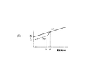
- the structure is focused on the surface B. That is, assuming that the height of the inner scroll US on the surface A on the upstream side is H1 and the height of the outlet surface B is H2, there is a relationship of H2 ⁇ H1.
- FIG. 5C shows the relationship between the axial length of the inner scroll US, that is, the height H in FIG. 5B in the circumferential direction.
- the height of the conventional inner scroll US decreases at a constant rate as shown by the solid line in FIG. 5C, but in the case of the sixth embodiment, this height decreases sharply at the tongue 21 exit portion.
- the tongue portion 21 disappears as shown by the solid line in FIG. 5D before and after the exit portion of the tongue portion 21 and the area is rapidly expanded there. The sudden change of the area can be prevented as shown by the broken line in FIG.
- the upstream side surface A of the inner scroll US is rapidly reduced at the outlet surface B, and the tip end portion of the tongue portion 21 is connected.
- the gas flow from the radially outer side to the inner side in the vicinity of the tongue portion is avoided to suppress the decrease in turbine performance, and the thermal stress due to the formation of the tongue portion is maximally reduced.
Landscapes
- Engineering & Computer Science (AREA)
- Mechanical Engineering (AREA)
- General Engineering & Computer Science (AREA)
- Supercharger (AREA)
Abstract
Description
図6において、符号1はタービンケーシングを示し、該タービンケーシング1内には渦巻き状のスクロール4が形成され、また、タービンケーシング1の内周にはガス出口通路5が形成されている。
前記タービンケーシング1には、軸受ハウジング9が固定され、該軸受ハウジング9にはコンプレッサハウジング6が固定されている。
タービンロータは符号10で示され、該タービンロータ10の外周に複数のタービン動翼3が円周方向等間隔に固着されている。
かかる排気ターボ過給機において、エンジンからの排気ガスは、前記スクロール4に入り、該スクロール4の渦巻きに沿って周回しながら、タービン動翼3の外周側入口4cの端面から該タービン動翼3に流入し、タービンロータ10の中心側に向かい半径方向に流れてタービンロータ10に膨張仕事をなした後、軸方向に流出してガス出口通路5から機外に排出される。
このため、排気ガスの流動時に舌部のウェイク(低速領域)30が発生する。該ウェイク30は、図7(A)の場合よりも、舌部21の厚い図7(B)の方が大きくなって、従って舌部21のウェイク30によるタービン性能の低下も大きくなる。
前記スクロールは、ガス入口部内周に形成される舌部のライン上の一定範囲の長さに仕切板を形成するか若しくはスクロールのガス入口部内周に形成される舌部の出口部分におけるスクロール側壁間の高さを減少させて、舌部の近傍の径方向外側から内側に向かうガスの流れを回避したことを特徴とする。
特に本発明は前記スクロールは、ガス入口部内周に形成される舌部のライン上の一定範囲の長さに仕切板を形成し、該仕切板の上部空間のガスの下部空間への流れを該仕切板で抑制したことを特徴とする。
かかる発明においては、前記仕切板を前記スクロールのタービン動翼のシュラウド側に続くタービンケーシング壁面に突設するのが好ましい。
(1)前記仕切板の下部空間の流路面積を、周方向に減少させることにより絞り効果を発生させ、前記下部空間から仕切板の上部空間へのガスの流れを生成する。
(2)前記仕切板の上部空間の流路面積を減少させず、且つ前記仕切板の下部空間の流路面積を周方向に減少させることにより、上部空間から下部空間へのガスの流れを抑制する。
前記スクロールのガス入口部内周に形成される舌部のライン上の一定範囲の長さに仕切部材を配置し、該仕切部材は、円周方向に沿って端部の通路面積が広く該舌部に近づくほど通路面積が狭くなるように通路面積が円周方向に変化するように構成したことを特徴とする。
前記舌部のライン上の一定範囲の長さに仕切板を、とくにタービン動翼のシュラウド側に続くタービンケーシング壁面に突設すれば、該仕切板によりスクロールの上部空間側から下部空間側に向かう排気ガス流を抑制できる。
従って、かかる上部空間側から下部空間側に向かう排気ガス流が低減され、ウェイクの発生を抑制でき、これによりタービン効率の低下を防止できる。
径方向内側に向かうガス流によって、仕切板からウェイクが発生するが、仕切板の端部に上部空間側に向かう傾斜面に構成することにより、ガス流の方向に対する仕切板の端部の投影面積が縮小され、これによりウェイクが低減される。
仕切板の下部空間の流路面積を、周方向に減少させることにより絞り効果を発生させれば、仕切板の下部空間から上部空間に排気ガスが流れようとする力が働き、上部空間側から舌部の下部空間側に向かう流れ込みを抑制できる。
仕切板の上部空間の流路面積を減少させないので、上部空間側から舌部の下部空間側に向かう流れ込みを抑制できる。
排気ガスの流れ込みの少ない反舌部の端部を広く、また最も排気ガスの流れ込みの大きい舌部近傍の通路面積を狭くすることにより、排気ガスの流れ込みを抑制できる。また前記により通路の投影面積を減少できるため、舌部のウェイクを低減できる。
尚、仕切部材の、円周方向に沿って端部の通路面積が広く、序々に通路面積を狭くして行き、舌部に近づくと通路面積が最も狭くなるように形成する。
舌部の出口部分におけるスクロールの軸方向の高さを減少させることで、すなわち通路断面積が舌部の出口部分において絞られることで、舌部が無くなることによる急激な通路面積の拡大を防ぎ、スムーズに面積が減少して舌部後流の乱れを低減でき、これによって舌部の内側スクロールのウェイクを低減できる。
図6において、符号1はタービンケーシングを示し、該タービンケーシング1内には渦巻き状のスクロール4が形成され、また、タービンケーシング1の内周にはガス出口通路5が形成されている。
前記タービンケーシング1には軸受ハウジング9が固定され、該軸受ハウジング9にはコンプレッサハウジング6が固定されている。
タービンロータは符号10で示され、該タービンロータ10の外周に複数のタービン動翼3が円周方向等間隔に固着されている。
本発明は、かかるウェイクの発生を抑制して、該ウェイクの発生によるタービン効率の低下を防止するものである。
エンジンからの排気ガスは、タービンケーシング1のスクロール4に入り、該スクロール4の渦巻きに沿って周回しながら、タービン動翼3の外周側入口4cの端面から該タービン動翼3に流入し、タービンロータ10の中心側に向かい半径方向に流れてタービンロータ10に膨張仕事をなした後、軸方向に流出してガス出口通路5から機外に排出される。回転軸心は20zで示す。
即ち、前記仕切板20は、図1(A)に示すように、円周方向位置において、前記舌部21のライン上、つまり舌部21中心を延長したライン上の、前記舌部21の端部と回転中心20zとを結ぶ線から反舌部21側の角θは少なくとも10°以上が妥当である。
図1(A)のように、該仕切板20と舌部21との間には、開口部21sが形成される。
かかる仕切板20を設けたことにより前記スクロール4は、該仕切板20よりも外側のスクロール外側4aと該仕切板20よりも内側のスクロール内側4bとに分けられるとともに、前記仕切板20のない部分は開口部4hとなっている。
これにより、前記仕切板20の上部空間のスクロール外側4aとガスの下部空間のスクロール内側4bへの流れを、該仕切板20で抑制している。
従って、かかるスクロール外側(上部空間)4aからスクロール内側(下部空間)4bに向かう排気ガス流が低減され、前記のように、ウェイク30の発生を抑制でき、これによりタービン効率の低下を防止できる。
また、前記仕切板20に開口部21sを形成できるため、該仕切板20及び舌部21の形成による熱拘束が少なくなり、従ってかかる拘束による熱応力が低減できる。
本発明の第2実施例では、前記仕切板20のスクロール内側(下部空間)4bの流路面積を、周方向に減少させることにより絞り効果を発生させ、前記スクロール内側(下部空間)4bから仕切板20のスクロール外側(上部空間)4aへのガスの流れを生成している。
このように構成すれば、仕切板20のスクロール内側(下部空間)4bの流路面積を、周方向に減少させることにより絞り効果を発生させれば、仕切板20のスクロール内側(下部空間)4bからスクロール外側(上部空間)4aに排気ガスが流れようとする力が働き、スクロール外側(上部空間)4a側から舌部21のスクロール内側(下部空間)4b側に、向かう流れ込みを抑制できる。
このように構成すれば、仕切板20のスクロール外側(上部空間)4aの流路面積を減少させないので、スクロール外側(上部空間)4aから舌部21のスクロール内側(下部空間)4bに向かう流れ込みを抑制できる。
第2,3実施例において、その他の構成は、前記第1実施例と同様であり、これと同一の部材は同一の符号で示す。
本発明の第4実施例では、仕切板20の、端部の断面形状をスクロール外側(上部空間)4aからスクロール内側(下部空間)4bに切断してスクロール外側(上部空間)4aに向かう傾斜面20yに構成している。即ち、図3(B)のように、スクロール外側(上部空間)4aが幅S1,スクロール内側(下部空間)4bが幅S2のように、幅Sを直線的に変化させている。
第4実施例において、その他の構成は、前記第1実施例と同様であり、これと同一の部材は同一の符号で示す。
本発明の第5実施例では、スクロール4のガス入口部内周に形成される舌部21のライン上の一定範囲の長さに仕切部材20aを配置し、該仕切部材20aは、径方向外側の上部空間と径方向内側の下部空間とを連通する開口部H(図4(B))の通路幅が円周方向に沿って端部の通路幅が広く該舌部に近づくほど通路幅が狭くなるように円周方向に変化している。すなわち図4(B)に示すように円周方向Wに沿って、端部の通路幅bが広く該舌部21に近づくほど通路幅aが狭くなるように、通路幅a、bが円周方向Wに変化するように構成している。
前記仕切部材20aは、円周方向Wに沿って端部の通路幅bが広く、序々に通路幅狭くして行き、舌部21に近づくと通路幅aが最も狭くなるように、通路幅を連続的に変化するように形成している。
第5実施例において、その他の構成は、前記第1実施例と同様であり、これと同一の部材は同一の符号で示す。
本発明の第6実施例では、前記第1実施例から第5実施例のようにスクロールの一方の壁から他方の壁に向かって途中まで仕切板20、仕切部材20aがある構造でなく、図5(B)に示すように、舌部21の出口部分20Cの一方の壁K1から他方の壁K2への高さ(H)が絞られて絞り部分Mを形成している。
すなわち、舌部21の内側に位置する内側スクロールUS、その内側スクロールUSの舌部先端側に存在する先端部20Cが図5(B)のように、舌部21出口部分において上流側面Aから出口面Bにかけて絞った構造としたものである。
即ち、上流側の面Aにおける内側スクロールUSの高さをH1とし、出口面Bの高さをH2とするとH2<H1の関係にある。
こうすることで舌部21の出口部分の前後にて、従来は、図5(D)の実線のように舌分21が無くなりそこで面積が急拡大するが、第6実施例の如く内側スクロールUSの高さを減少させることにより図5(D)の破線の如く面積の急変を防ぐことができる。
Claims (8)
- 作動ガスをタービンケーシング内に形成された渦巻状のスクロールから該スクロールの内側に位置するタービンロータのタービン動翼へと半径方向に流入させて該タービン動翼に作用させた後、軸方向に流出させることにより該タービンロータを回転駆動するように構成されたラジアルタービンのスクロール構造において、
前記スクロールは、ガス入口部内周に形成される舌部のライン上の一定範囲の長さに仕切板を形成するか若しくはスクロールのガス入口部内周に形成される舌部の出口部分におけるスクロール側壁間の高さを減少させて、舌部の近傍の径方向外側から内側に向かうガスの流れを回避したことを特徴とするラジアルタービンのスクロール構造。 - 請求項1記載のラジアルタービンのスクロール構造において、
前記スクロールは、ガス入口部内周に形成される舌部のライン上の一定範囲の長さに仕切板を形成し、該仕切板の径方向外側の上部空間のガスが径方向内側の下部空間へ流れるのを該仕切板で抑制したことを特徴とするラジアルタービンのスクロール構造。 - 前記仕切板を、前記スクロールのタービン動翼のシュラウド側に続くタービンケーシング壁面に突設したことを特徴とする請求項2記載のラジアルタービンのスクロール構造。
- 前記仕切板の端部の断面形状を上部空間側から下部空間側に切断して径内側に向かうに従って、前記スクロール内壁面との開口幅が縮小するように傾斜面に構成したことを特徴とする請求項2記載のラジアルタービンのスクロール構造。
- 前記仕切板の下部空間の流路面積を、周方向に減少させることにより絞り効果を発生させ、前記下部空間から仕切板の上部空間へのガスの流れを生成することを特徴とする請求項2記載のラジアルタービンのスクロール構造。
- 前記仕切板の上部空間の流路面積を減少させず、且つ前記仕切板の下部空間の流路面積を周方向に減少させることにより、上部空間から下部空間へのガスの流れを抑制することを特徴とする請求項5記載のラジアルタービンのスクロール構造。
- 請求項1記載のラジアルタービンのスクロール構造において、
前記スクロールのガス入口部内周に形成される舌部のライン上の一定範囲の長さに仕切部材を配置し、該仕切部材は、仕切板の径方向外側の上部空間と径方向内側の下部空間とを連通する通路幅が円周方向に沿って端部の通路幅が広く該舌部に近づくほど通路幅が狭くなるように円周方向に変化するように構成したことを特徴とするラジアルタービンのスクロール構造。 - 請求項1記載のラジアルタービンのスクロール構造において、
前記スクロールのガス入口部内周に形成される舌部の出口部分におけるスクロール側壁間の高さを減少させて、前記舌部の出口部分における通路断面積を絞るように構成したことを特徴とするラジアルタービンのスクロール構造。
Priority Applications (5)
| Application Number | Priority Date | Filing Date | Title |
|---|---|---|---|
| JP2010534778A JP5047364B2 (ja) | 2008-10-20 | 2009-10-14 | ラジアルタービンのスクロール構造 |
| CN200980107185.3A CN101960120B (zh) | 2008-10-20 | 2009-10-14 | 径流式涡轮的涡管结构 |
| KR1020107018415A KR101200627B1 (ko) | 2008-10-20 | 2009-10-14 | 래디얼 터빈의 스크롤 구조 |
| EP09821956.1A EP2249002B1 (en) | 2008-10-20 | 2009-10-14 | Radial turbine scroll structure |
| US12/867,272 US8591177B2 (en) | 2008-10-20 | 2009-10-14 | Structure of radial turbine scroll |
Applications Claiming Priority (2)
| Application Number | Priority Date | Filing Date | Title |
|---|---|---|---|
| JP2008-269466 | 2008-10-20 | ||
| JP2008269466 | 2008-10-20 |
Publications (1)
| Publication Number | Publication Date |
|---|---|
| WO2010047259A1 true WO2010047259A1 (ja) | 2010-04-29 |
Family
ID=42119300
Family Applications (1)
| Application Number | Title | Priority Date | Filing Date |
|---|---|---|---|
| PCT/JP2009/067798 WO2010047259A1 (ja) | 2008-10-20 | 2009-10-14 | ラジアルタービンのスクロール構造 |
Country Status (6)
| Country | Link |
|---|---|
| US (1) | US8591177B2 (ja) |
| EP (1) | EP2249002B1 (ja) |
| JP (1) | JP5047364B2 (ja) |
| KR (1) | KR101200627B1 (ja) |
| CN (1) | CN101960120B (ja) |
| WO (1) | WO2010047259A1 (ja) |
Cited By (6)
| Publication number | Priority date | Publication date | Assignee | Title |
|---|---|---|---|---|
| US20130266432A1 (en) * | 2010-12-28 | 2013-10-10 | Mitsubishi Heavy Industries, Ltd. | Scroll structure of centrifugal compressor |
| US20170022830A1 (en) * | 2013-12-16 | 2017-01-26 | Cummins Ltd | Turbine housing |
| US9874222B2 (en) | 2012-01-11 | 2018-01-23 | Mitsubishi Heavy Industries, Ltd. | Scroll structure of turbine housing |
| JP2018080620A (ja) * | 2016-11-15 | 2018-05-24 | 株式会社豊田中央研究所 | タービンユニット、ターボチャージャ |
| JP2018150843A (ja) * | 2017-03-10 | 2018-09-27 | 株式会社Ihi | タービンハウジング |
| US11261746B2 (en) | 2018-06-29 | 2022-03-01 | Ihi Corporation | Turbine and turbocharger |
Families Citing this family (10)
| Publication number | Priority date | Publication date | Assignee | Title |
|---|---|---|---|---|
| JP4838830B2 (ja) * | 2008-08-28 | 2011-12-14 | 三菱重工業株式会社 | 可変容量排気ガスタービンの製造方法 |
| US9206817B2 (en) | 2010-08-31 | 2015-12-08 | Nippon Soken, Inc. | Centrifugal blower |
| FR2968717B1 (fr) * | 2010-12-14 | 2014-06-13 | Faurecia Sys Echappement | Carter de turbine pour turbocompresseur, turbine et turbocompresseur correspondants. |
| JP5660878B2 (ja) * | 2010-12-20 | 2015-01-28 | 三菱重工業株式会社 | ラジアルタービンあるいは斜流タービンのスクロール部構造 |
| WO2013065154A1 (ja) * | 2011-11-02 | 2013-05-10 | トヨタ自動車 株式会社 | タービンハウジング及び排気タービン過給機 |
| CN106401669A (zh) * | 2015-07-31 | 2017-02-15 | 新乡航空工业(集团)有限公司 | 一种中间级涡轮出口流道结构 |
| DE102015014900A1 (de) * | 2015-10-22 | 2017-04-27 | GM Global Technology Operations LLC (n. d. Ges. d. Staates Delaware) | Radialturbinengehäuse |
| DE102016008273A1 (de) | 2016-03-15 | 2017-09-21 | Daimler Ag | Turbinengehäuse für eine Turbine eines Abgasturboladers |
| JP6441402B2 (ja) * | 2017-03-30 | 2018-12-19 | 株式会社ケーヒン | 遠心式送風機 |
| CN213743545U (zh) | 2019-10-14 | 2021-07-20 | 博格华纳公司 | 涡轮增压器和用于涡轮增压器的涡轮机壳体 |
Citations (3)
| Publication number | Priority date | Publication date | Assignee | Title |
|---|---|---|---|---|
| JP2002004871A (ja) * | 2000-04-19 | 2002-01-09 | Aisin Takaoka Ltd | 過給機のタービンハウジング |
| JP2003120303A (ja) | 2001-10-19 | 2003-04-23 | Mitsubishi Heavy Ind Ltd | ラジアルタービンのスクロール構造 |
| JP2007113501A (ja) * | 2005-10-21 | 2007-05-10 | Mitsubishi Heavy Ind Ltd | 排気ターボ式過給機 |
Family Cites Families (11)
| Publication number | Priority date | Publication date | Assignee | Title |
|---|---|---|---|---|
| US3687360A (en) * | 1969-11-19 | 1972-08-29 | Beloit Corp | Noise suppressing baffle discharge exit |
| JPS58162703A (ja) * | 1982-03-24 | 1983-09-27 | Nissan Motor Co Ltd | ラジアルタ−ビンのタ−ビンケ−シング製造方法 |
| DE3346472C2 (de) * | 1982-12-28 | 1991-09-12 | Nissan Motor Co., Ltd., Yokohama, Kanagawa | Radialturbine mit veränderlicher Leistung |
| US4678397A (en) * | 1983-06-15 | 1987-07-07 | Nissan Motor Co., Ltd. | Variable-capacitance radial turbine having swingable tongue member |
| US4781528A (en) * | 1987-09-09 | 1988-11-01 | Mitsubishi Jukogyo Kabushiki Kaisha | Variable capacity radial flow turbine |
| JPH0886299A (ja) * | 1994-09-16 | 1996-04-02 | Nippondenso Co Ltd | 遠心式送風機 |
| US6742989B2 (en) | 2001-10-19 | 2004-06-01 | Mitsubishi Heavy Industries, Ltd. | Structures of turbine scroll and blades |
| JP3876185B2 (ja) | 2002-04-26 | 2007-01-31 | 三菱重工業株式会社 | 可変容量タービン及びこれを用いた可変容量ターボチャージャ |
| JP2004092481A (ja) | 2002-08-30 | 2004-03-25 | Mitsubishi Heavy Ind Ltd | 可変容量タービン及びこれを備えた可変容量ターボチャージャ |
| US7269950B2 (en) * | 2004-05-05 | 2007-09-18 | Precision Industries, Inc. | Staged turbocharger |
| US7428814B2 (en) * | 2006-03-08 | 2008-09-30 | Melvin Hess Pedersen | Turbine assemblies and related systems for use with turbochargers |
-
2009
- 2009-10-14 WO PCT/JP2009/067798 patent/WO2010047259A1/ja active Application Filing
- 2009-10-14 US US12/867,272 patent/US8591177B2/en active Active
- 2009-10-14 EP EP09821956.1A patent/EP2249002B1/en active Active
- 2009-10-14 CN CN200980107185.3A patent/CN101960120B/zh active Active
- 2009-10-14 JP JP2010534778A patent/JP5047364B2/ja active Active
- 2009-10-14 KR KR1020107018415A patent/KR101200627B1/ko active IP Right Grant
Patent Citations (3)
| Publication number | Priority date | Publication date | Assignee | Title |
|---|---|---|---|---|
| JP2002004871A (ja) * | 2000-04-19 | 2002-01-09 | Aisin Takaoka Ltd | 過給機のタービンハウジング |
| JP2003120303A (ja) | 2001-10-19 | 2003-04-23 | Mitsubishi Heavy Ind Ltd | ラジアルタービンのスクロール構造 |
| JP2007113501A (ja) * | 2005-10-21 | 2007-05-10 | Mitsubishi Heavy Ind Ltd | 排気ターボ式過給機 |
Non-Patent Citations (1)
| Title |
|---|
| See also references of EP2249002A4 |
Cited By (8)
| Publication number | Priority date | Publication date | Assignee | Title |
|---|---|---|---|---|
| US20130266432A1 (en) * | 2010-12-28 | 2013-10-10 | Mitsubishi Heavy Industries, Ltd. | Scroll structure of centrifugal compressor |
| US9541094B2 (en) * | 2010-12-28 | 2017-01-10 | Mitsubishi Heavy Industries, Ltd. | Scroll structure of centrifugal compressor |
| US9874222B2 (en) | 2012-01-11 | 2018-01-23 | Mitsubishi Heavy Industries, Ltd. | Scroll structure of turbine housing |
| US20170022830A1 (en) * | 2013-12-16 | 2017-01-26 | Cummins Ltd | Turbine housing |
| US10487676B2 (en) * | 2013-12-16 | 2019-11-26 | Cummins Ltd. | Turbine housing |
| JP2018080620A (ja) * | 2016-11-15 | 2018-05-24 | 株式会社豊田中央研究所 | タービンユニット、ターボチャージャ |
| JP2018150843A (ja) * | 2017-03-10 | 2018-09-27 | 株式会社Ihi | タービンハウジング |
| US11261746B2 (en) | 2018-06-29 | 2022-03-01 | Ihi Corporation | Turbine and turbocharger |
Also Published As
| Publication number | Publication date |
|---|---|
| JPWO2010047259A1 (ja) | 2012-03-22 |
| KR101200627B1 (ko) | 2012-11-12 |
| KR20100117082A (ko) | 2010-11-02 |
| US20110008162A1 (en) | 2011-01-13 |
| JP5047364B2 (ja) | 2012-10-10 |
| CN101960120B (zh) | 2013-03-06 |
| EP2249002B1 (en) | 2018-10-03 |
| EP2249002A4 (en) | 2017-10-11 |
| CN101960120A (zh) | 2011-01-26 |
| US8591177B2 (en) | 2013-11-26 |
| EP2249002A1 (en) | 2010-11-10 |
Similar Documents
| Publication | Publication Date | Title |
|---|---|---|
| WO2010047259A1 (ja) | ラジアルタービンのスクロール構造 | |
| EP1304445B1 (en) | Structure of radial turbine scroll and blades | |
| JP5221985B2 (ja) | 遠心圧縮機 | |
| JP5433560B2 (ja) | タービンスクロール部構造 | |
| WO2011007467A1 (ja) | インペラおよび回転機械 | |
| JP2009281197A (ja) | 斜流タービン | |
| JP2007127108A (ja) | 排気ターボ過給機のコンプレッサ | |
| JP2001289050A (ja) | 可変容量ターボ過給機 | |
| US20100040458A1 (en) | Axial fan casing design with circumferentially spaced wedges | |
| JP2009047043A (ja) | 軸流タービン | |
| JP5936710B2 (ja) | 可変容量型排気ターボ過給機 | |
| JP6265353B2 (ja) | 開閉弁装置、及び回転機械 | |
| WO2011007466A1 (ja) | インペラおよび回転機械 | |
| JP3534728B2 (ja) | ラジアルタービンのスクロール構造 | |
| JP2011132810A (ja) | ラジアルタービンの動翼 | |
| WO2018116394A1 (ja) | ターボチャージャ及びターボチャージャのノズルベーン並びにタービン | |
| JP5427900B2 (ja) | 斜流タービン | |
| JP2009074542A (ja) | 可変容量ターボチャージャ | |
| JP6200350B2 (ja) | ラジアルタービン又は斜流タービン | |
| JP6864119B2 (ja) | タービン及びターボチャージャ | |
| JP2005299573A (ja) | 風力機械のディフューザおよび斜流圧縮機のディフューザ、ディフューザ | |
| WO2023203813A1 (ja) | 遠心圧縮機 | |
| JP6759463B2 (ja) | ターボチャージャ用タービン及びターボチャージャ | |
| JP2008163761A (ja) | ラジアルタービン | |
| JP2009236121A (ja) | 斜流圧縮機のディフューザ |
Legal Events
| Date | Code | Title | Description |
|---|---|---|---|
| WWE | Wipo information: entry into national phase |
Ref document number: 200980107185.3 Country of ref document: CN |
|
| 121 | Ep: the epo has been informed by wipo that ep was designated in this application |
Ref document number: 09821956 Country of ref document: EP Kind code of ref document: A1 |
|
| WWE | Wipo information: entry into national phase |
Ref document number: 2010534778 Country of ref document: JP |
|
| WWE | Wipo information: entry into national phase |
Ref document number: 2009821956 Country of ref document: EP |
|
| ENP | Entry into the national phase |
Ref document number: 20107018415 Country of ref document: KR Kind code of ref document: A |
|
| WWE | Wipo information: entry into national phase |
Ref document number: 12867272 Country of ref document: US |
|
| NENP | Non-entry into the national phase |
Ref country code: DE |