WO2010044148A1 - 内燃機関の制御装置 - Google Patents
内燃機関の制御装置 Download PDFInfo
- Publication number
- WO2010044148A1 WO2010044148A1 PCT/JP2008/068650 JP2008068650W WO2010044148A1 WO 2010044148 A1 WO2010044148 A1 WO 2010044148A1 JP 2008068650 W JP2008068650 W JP 2008068650W WO 2010044148 A1 WO2010044148 A1 WO 2010044148A1
- Authority
- WO
- WIPO (PCT)
- Prior art keywords
- air
- fuel ratio
- internal combustion
- combustion engine
- amount
- Prior art date
Links
Images


Classifications
-
- F—MECHANICAL ENGINEERING; LIGHTING; HEATING; WEAPONS; BLASTING
- F02—COMBUSTION ENGINES; HOT-GAS OR COMBUSTION-PRODUCT ENGINE PLANTS
- F02D—CONTROLLING COMBUSTION ENGINES
- F02D41/00—Electrical control of supply of combustible mixture or its constituents
- F02D41/30—Controlling fuel injection
- F02D41/3011—Controlling fuel injection according to or using specific or several modes of combustion
- F02D41/3017—Controlling fuel injection according to or using specific or several modes of combustion characterised by the mode(s) being used
- F02D41/3023—Controlling fuel injection according to or using specific or several modes of combustion characterised by the mode(s) being used a mode being the stratified charge spark-ignited mode
-
- F—MECHANICAL ENGINEERING; LIGHTING; HEATING; WEAPONS; BLASTING
- F02—COMBUSTION ENGINES; HOT-GAS OR COMBUSTION-PRODUCT ENGINE PLANTS
- F02D—CONTROLLING COMBUSTION ENGINES
- F02D41/00—Electrical control of supply of combustible mixture or its constituents
- F02D41/02—Circuit arrangements for generating control signals
- F02D41/14—Introducing closed-loop corrections
-
- F—MECHANICAL ENGINEERING; LIGHTING; HEATING; WEAPONS; BLASTING
- F02—COMBUSTION ENGINES; HOT-GAS OR COMBUSTION-PRODUCT ENGINE PLANTS
- F02D—CONTROLLING COMBUSTION ENGINES
- F02D37/00—Non-electrical conjoint control of two or more functions of engines, not otherwise provided for
- F02D37/02—Non-electrical conjoint control of two or more functions of engines, not otherwise provided for one of the functions being ignition
-
- F—MECHANICAL ENGINEERING; LIGHTING; HEATING; WEAPONS; BLASTING
- F02—COMBUSTION ENGINES; HOT-GAS OR COMBUSTION-PRODUCT ENGINE PLANTS
- F02D—CONTROLLING COMBUSTION ENGINES
- F02D41/00—Electrical control of supply of combustible mixture or its constituents
- F02D41/0002—Controlling intake air
-
- F—MECHANICAL ENGINEERING; LIGHTING; HEATING; WEAPONS; BLASTING
- F02—COMBUSTION ENGINES; HOT-GAS OR COMBUSTION-PRODUCT ENGINE PLANTS
- F02D—CONTROLLING COMBUSTION ENGINES
- F02D41/00—Electrical control of supply of combustible mixture or its constituents
- F02D41/02—Circuit arrangements for generating control signals
- F02D41/04—Introducing corrections for particular operating conditions
-
- F—MECHANICAL ENGINEERING; LIGHTING; HEATING; WEAPONS; BLASTING
- F02—COMBUSTION ENGINES; HOT-GAS OR COMBUSTION-PRODUCT ENGINE PLANTS
- F02D—CONTROLLING COMBUSTION ENGINES
- F02D41/00—Electrical control of supply of combustible mixture or its constituents
- F02D41/30—Controlling fuel injection
-
- F—MECHANICAL ENGINEERING; LIGHTING; HEATING; WEAPONS; BLASTING
- F02—COMBUSTION ENGINES; HOT-GAS OR COMBUSTION-PRODUCT ENGINE PLANTS
- F02D—CONTROLLING COMBUSTION ENGINES
- F02D41/00—Electrical control of supply of combustible mixture or its constituents
- F02D41/30—Controlling fuel injection
- F02D41/38—Controlling fuel injection of the high pressure type
- F02D41/40—Controlling fuel injection of the high pressure type with means for controlling injection timing or duration
-
- F—MECHANICAL ENGINEERING; LIGHTING; HEATING; WEAPONS; BLASTING
- F02—COMBUSTION ENGINES; HOT-GAS OR COMBUSTION-PRODUCT ENGINE PLANTS
- F02D—CONTROLLING COMBUSTION ENGINES
- F02D43/00—Conjoint electrical control of two or more functions, e.g. ignition, fuel-air mixture, recirculation, supercharging or exhaust-gas treatment
-
- F—MECHANICAL ENGINEERING; LIGHTING; HEATING; WEAPONS; BLASTING
- F02—COMBUSTION ENGINES; HOT-GAS OR COMBUSTION-PRODUCT ENGINE PLANTS
- F02D—CONTROLLING COMBUSTION ENGINES
- F02D41/00—Electrical control of supply of combustible mixture or its constituents
- F02D41/02—Circuit arrangements for generating control signals
- F02D41/14—Introducing closed-loop corrections
- F02D41/1401—Introducing closed-loop corrections characterised by the control or regulation method
- F02D2041/1433—Introducing closed-loop corrections characterised by the control or regulation method using a model or simulation of the system
- F02D2041/1434—Inverse model
-
- F—MECHANICAL ENGINEERING; LIGHTING; HEATING; WEAPONS; BLASTING
- F02—COMBUSTION ENGINES; HOT-GAS OR COMBUSTION-PRODUCT ENGINE PLANTS
- F02D—CONTROLLING COMBUSTION ENGINES
- F02D2250/00—Engine control related to specific problems or objectives
- F02D2250/18—Control of the engine output torque
-
- F—MECHANICAL ENGINEERING; LIGHTING; HEATING; WEAPONS; BLASTING
- F02—COMBUSTION ENGINES; HOT-GAS OR COMBUSTION-PRODUCT ENGINE PLANTS
- F02D—CONTROLLING COMBUSTION ENGINES
- F02D41/00—Electrical control of supply of combustible mixture or its constituents
- F02D41/30—Controlling fuel injection
- F02D41/3011—Controlling fuel injection according to or using specific or several modes of combustion
- F02D41/3017—Controlling fuel injection according to or using specific or several modes of combustion characterised by the mode(s) being used
- F02D41/3023—Controlling fuel injection according to or using specific or several modes of combustion characterised by the mode(s) being used a mode being the stratified charge spark-ignited mode
- F02D41/3029—Controlling fuel injection according to or using specific or several modes of combustion characterised by the mode(s) being used a mode being the stratified charge spark-ignited mode further comprising a homogeneous charge spark-ignited mode
-
- Y—GENERAL TAGGING OF NEW TECHNOLOGICAL DEVELOPMENTS; GENERAL TAGGING OF CROSS-SECTIONAL TECHNOLOGIES SPANNING OVER SEVERAL SECTIONS OF THE IPC; TECHNICAL SUBJECTS COVERED BY FORMER USPC CROSS-REFERENCE ART COLLECTIONS [XRACs] AND DIGESTS
- Y02—TECHNOLOGIES OR APPLICATIONS FOR MITIGATION OR ADAPTATION AGAINST CLIMATE CHANGE
- Y02T—CLIMATE CHANGE MITIGATION TECHNOLOGIES RELATED TO TRANSPORTATION
- Y02T10/00—Road transport of goods or passengers
- Y02T10/10—Internal combustion engine [ICE] based vehicles
- Y02T10/40—Engine management systems
Definitions
- the present invention relates to a control device for an internal combustion engine, and more particularly to a control device for an internal combustion engine in which the air-fuel ratio in the vicinity of a spark plug and the air-fuel ratio in the entire cylinder are different.
- the required indicated torque requested by the driver is calculated based on the accelerator opening, and the target air-fuel ratio is determined inside the control device. Then, the required indicated torque is corrected by the torque efficiency with respect to the ignition timing and the torque efficiency with respect to the target air-fuel ratio, and the target throttle opening is determined based on the target air amount obtained from the corrected torque. Further, the intake air delay correction amount is calculated from the target air amount and the engine speed, and the ignition timing retardation amount is calculated from the estimated torque determined from the intake delay correction amount and the above-described correction torque, and the basic amount determined from the in-cylinder air amount.
- the final ignition timing is determined from the ignition timing and the ignition timing retardation amount. Further, the target fuel injection amount is determined from the in-cylinder air amount and the target air-fuel ratio. That is, Japanese Patent Laid-Open No. 2003-301766 discloses a throttle opening, an ignition timing, and a fuel injection so as to realize both the requested indicated torque that is a request from the driver and the target air-fuel ratio that is a request in the control device. A technique of setting three types of manipulated variables is disclosed.
- homogeneous combustion and stratified combustion are known as combustion modes of an air-fuel mixture in an internal combustion engine.
- Homogeneous combustion is a combustion mode in which air and fuel are mixed homogeneously in a cylinder and burned.
- stratified combustion is a combustion mode in which a thick air-fuel mixture layer is formed in the vicinity of the spark plug, and a thin air-fuel mixture is formed around it to burn.
- the air-fuel ratio in the vicinity of the spark plug matches the air-fuel ratio (average air-fuel ratio) in the entire cylinder.
- fuel collects in the vicinity of the spark plug, so that the air-fuel ratio of the combustion gas there differs from the air-fuel ratio in the entire cylinder.
- the technique described in Japanese Patent Application Laid-Open No. 2003-301766 is considered to be based on an internal combustion engine that performs homogeneous combustion.
- torque control can be performed with three types of actuator operation amounts of throttle opening, ignition timing, and fuel injection amount as in the technique described in Japanese Patent Laid-Open No. 2003-301766.
- the torque can be controlled by the intake air amount, the ignition timing, and the combustion air-fuel ratio, but in the case of homogeneous combustion, the air-fuel ratio in the vicinity of the spark plug matches the air-fuel ratio in the entire cylinder. Therefore, the intake air amount is determined by the throttle opening, and the air-fuel ratio of the entire cylinder is determined by the intake air amount and the fuel injection amount, whereby the torque can be controlled by them.
- torque-ignition timing characteristics the relationship between torque and ignition timing (hereinafter referred to as torque-ignition timing characteristics) is It will be different.
- the required indicated torque is a requirement relating to drivability
- the target air-fuel ratio is a requirement relating to exhaust gas.
- Both drivability and exhaust gas are functions of the internal combustion engine. In addition to these functions, there are various functions of the internal combustion engine such as fuel consumption and knock. Then, there is a request for each function. For example, if the function is fuel consumption, there is a request to increase combustion efficiency and a request to reduce pump loss. Further, if the function is exhaust gas, there is a demand for increasing the exhaust gas temperature and a demand for promoting the reaction in the catalyst.
- the internal combustion engine has various functions, and there are various demands having different dimensions for each function.
- the technique described in Japanese Patent Application Laid-Open No. 2003-301766 only fulfills some of the requirements, and there is still room for improvement in order to meet various requirements of the internal combustion engine.
- the present invention has been made in view of the above-described problems.
- requests regarding various functions of the internal combustion engine are required for the operation of each actuator. It is an object of the present invention to provide a control device for an internal combustion engine that accurately reflects these requirements and can appropriately realize those requirements.
- the control device and method for an internal combustion engine of the present invention controls an internal combustion engine in which the air-fuel ratio in the vicinity of the spark plug and the air-fuel ratio in the entire cylinder are different.
- Such an internal combustion engine includes an internal combustion engine such as stratified combustion that burns with intentionally non-uniform air-fuel ratio distribution in the cylinder.
- an internal combustion engine that results in non-uniformity in the air-fuel ratio distribution in the cylinder depending on the operating state is included in the control object of the present invention.
- three physical quantities, torque, efficiency, and air-fuel ratio are used as control quantities for the internal combustion engine. Then, at least a part of the requests related to the function of the internal combustion engine is aggregated into these three types of physical quantities, so that a target value for each controlled variable is set.
- the output of the internal combustion engine includes heat and exhaust gas in addition to the torque, and various functions of the internal combustion engine are determined by the entire output. Torque, efficiency, and air-fuel ratio are three factors that determine the output of the internal combustion engine. Therefore, if at least a part of the requests related to various functions of the internal combustion engine is aggregated into the three types of physical quantities to obtain the control amount target value, these requests can be appropriately reflected in the output of the internal combustion engine.
- the three operation amounts of the opening amount of the intake air amount adjusting valve, the ignition timing, and the fuel injection amount are set.
- the amount of intake air in the cylinder can be adjusted by manipulating the opening of the intake air amount adjustment valve, the efficiency can be mainly controlled by manipulating the ignition timing, and the fuel injection amount can be mainly manipulated.
- the air-fuel ratio of the entire cylinder can be controlled.
- the fourth operation amount that can adjust the in-cylinder air-fuel ratio distribution is further provided. Is set.
- the torque can be controlled by adjusting the intake air amount, the efficiency, and the air-fuel ratio by the three kinds of manipulated variables.
- the air-fuel ratio in the vicinity of the spark plug and the air-fuel ratio in the entire cylinder are different, it is difficult to accurately control the torque only with the intake air amount, the efficiency, and the air-fuel ratio in the entire cylinder.
- the fourth operation amount includes the fuel injection timing into the cylinder.
- the fourth operation amount includes the valve timing of the intake valve adjusted by the valve timing variable mechanism, the valve opening degree of the swirl control valve or the tumble control valve, and the like. According to these manipulated variables, it is possible to adjust the transport speed when a rich air-fuel ratio gas mass generated by fuel injection in the cylinder or sucked from the intake port reaches the vicinity of the spark plug. .
- the set four types of operation amounts are output to the actuators to be operated.
- the opening of the intake air amount adjustment valve as the operation amount is output to the intake air amount adjustment valve.
- the intake air amount adjusting valve in the present invention includes an intake valve having a variable lift amount or operating angle.
- the ignition timing as the operation amount is output to the ignition device, and the fuel injection amount as the operation amount is output to the fuel injection device.
- the fuel injection device may inject fuel directly into the cylinder, or may inject fuel into the intake port. Alternatively, a part of the fuel may be injected into the intake port and the remaining fuel may be directly injected into the cylinder.
- the fourth operation amount is output to the fuel injection device together with the fuel injection amount, for example, when it is the fuel injection timing.
- the fuel injection device in this case is a device that can inject at least part of the fuel directly into the cylinder.
- it may be output to an actuator such as an intake valve timing variable mechanism, a swirl control valve, or a tumble control valve.
- the means for setting each operation amount generates a target value of the air-fuel ratio in the vicinity of the spark plug according to a predetermined rule, and the torque, efficiency, and air-fuel ratio 3
- Each manipulated variable is calculated from each target value of the control amount of the seed and the target value of the air-fuel ratio in the vicinity of the generated spark plug. Since the air-fuel ratio in the vicinity of the spark plug affects the torque-ignition timing characteristics, accurate torque control can be performed by generating the target value internally and using it for calculation of each manipulated variable.
- the means for setting each operation amount has a target value of the air-fuel ratio in the vicinity of the spark plug as a fixed value. By calculating each manipulated variable using this fixed value, the air-fuel ratio in the vicinity of the spark plug can be controlled to a constant air-fuel ratio.
- the means for setting each operation amount has a target value of the air-fuel ratio in the vicinity of the spark plug as a fixed value for each operating state of the internal combustion engine.
- the means for setting each operation amount previously defines a target correspondence between the air-fuel ratio in the entire cylinder and the air-fuel ratio in the vicinity of the spark plug. Using this target correspondence relationship, the air-fuel ratio target value near the spark plug is determined from the target value of the air-fuel ratio, which is the control amount, and each manipulated variable is calculated. It is possible to control to an optimal air-fuel ratio corresponding to the air-fuel ratio. According to this, the accuracy of torque control can be further increased.
- the means for setting each manipulated variable first adjusts the intake air amount based on the target values of the three control amounts of torque, efficiency, and air-fuel ratio.
- Three types of manipulated variables are calculated: valve opening, ignition timing, and fuel injection amount.
- the combustion air-fuel ratio required to realize the target values of the three control amounts of torque, efficiency, and air-fuel ratio under these three operation amounts is calculated as the target value of the air-fuel ratio in the vicinity of the spark plug.
- the fourth operation amount is calculated using the target value of the air-fuel ratio in the vicinity of the spark plug thus calculated.
- the combustion air is compensated so as to compensate for the deviation between each control value that can actually be realized and each target value.
- a target value of the fuel ratio is set, and finally the fourth manipulated variable is determined.
- the means for setting each manipulated variable first adjusts the intake air amount based on the target values of the three control amounts of torque, efficiency, and air-fuel ratio.
- the valve opening, ignition timing and fuel injection amount are calculated.
- the fourth operation amount is calculated from the fuel injection amount as the operation amount and the target value of the air-fuel ratio in the vicinity of the spark plug. That is, the direct calculation from the target values of the three control amounts of torque, efficiency, and air-fuel ratio is the three manipulated variables of the intake air amount adjustment valve opening, ignition timing, and fuel injection amount.
- the operation amount is calculated from the fuel injection amount and the target value of the air-fuel ratio of the combustion gas near the fire plug.
- Embodiment 1 of this invention It is a block diagram which shows the structure of the control apparatus of the internal combustion engine as Embodiment 1 of this invention. It is a block diagram which shows the structure of the implementation
- Throttle 4 Ignition device 6 Fuel injection device 8 Swirl control valve 10 Function request generation unit 12, 14, 16 Request output element 20 Target value setting unit 22 Torque adjustment element 24 Efficiency adjustment element 26 A / F adjustment element 30 Realization part 40 Realization Unit 302 conversion unit 304 target combustion A / F setting unit 312 conversion unit 314 target combustion A / F setting unit 316 conversion unit 322 conversion unit 324 target combustion A / F setting unit 326 conversion unit 402 conversion unit 404 target combustion A / F setting Part
- Embodiment 1 FIG. Embodiment 1 of the present invention will be described with reference to FIGS.
- the internal combustion engine according to the present embodiment is an internal combustion engine that performs operation by stratified combustion.
- a throttle 2 as an intake air amount adjustment valve
- an ignition device 4 for adjusting the ignition timing
- a fuel injection device 6 for directly injecting fuel into the cylinder.
- the specifications of the internal combustion engine according to the present embodiment are common to the second and third embodiments described later.
- control device of the present embodiment is configured as shown in the block diagram of FIG. In FIG. 1, each element of the control device is indicated by a block, and signal transmission (main) between the blocks is indicated by an arrow.
- signal transmission (main) between the blocks is indicated by an arrow.
- the control device is roughly composed of three parts 10, 20, and 30.
- the function request generator 10 is positioned at the top.
- a target value setting unit 20 is provided below the function request generation unit 10
- an implementation unit 30 is provided below the target value setting unit 20.
- Each of the actuators 2, 4, 6 described above is connected to the realization unit 30.
- various signals flow in the control device.
- An example of such a signal is a signal including information (hereinafter referred to as engine information) regarding the operating condition and operating state of the internal combustion engine.
- the engine information includes the engine speed, the output value of the throttle opening sensor, the output value of the air-fuel ratio sensor, the current actual ignition timing, the coolant temperature, the valve timings of the intake and exhaust valves, and the like.
- the function request generation unit 10 includes a plurality of request output elements 12, 14, and 16.
- the request output elements 12, 14, and 16 are provided for each function of the internal combustion engine.
- the functions of the internal combustion engine include drivability, exhaust gas, fuel consumption, noise, vibration, and the like. These can be rephrased as performance required for an internal combustion engine.
- the contents of the request output elements arranged in the function request generator 10 differ depending on what is required of the internal combustion engine and what is given priority.
- the required output element 12 is provided corresponding to the function relating to drivability
- the required output element 14 is provided corresponding to the function relating to exhaust gas
- the required output element 16 corresponding to the function relating to fuel consumption. Is provided.
- Requirement output elements 12, 14, and 16 digitize and output a request regarding the function of the internal combustion engine. Since the operation amounts of the actuators 2, 4, 6 are determined by calculation, it is possible to reflect the function request on the operation amounts of the actuators 2, 4, 6 by digitizing the request.
- three types of torque, efficiency, and A / F are used as physical quantities used for expressing function requirements. This is because requirements regarding various functions of the internal combustion engine such as drivability, exhaust gas, and fuel consumption can be expressed by any physical quantity of torque, efficiency, and A / F.
- the efficiency corresponds to the conversion efficiency of thermal energy that can be converted into torque, and is a dimensionless parameter that is set on the basis of when the ignition timing is MBT.
- the request output element 12 outputs a request related to drivability as a request value expressed by torque and efficiency.
- the request output element 14 outputs a request regarding exhaust gas as a required value expressed by efficiency or A / F.
- the request output element 16 outputs a request regarding fuel efficiency as a required value expressed in terms of efficiency and A / F.
- the request value output from each request output element 12, 14, 16 is not limited to one for each physical quantity. For example, from the request output element 12, not only the torque requested from the driver, but also the torque required from various devices related to vehicle control are output at the same time. The same applies to efficiency and A / F.
- the target value setting unit 20 sets a target value for the control amount of the internal combustion engine.
- the control device of the present embodiment uses the above-described torque, efficiency, and A / F as control amounts for the internal combustion engine.
- requirements regarding various functions of the internal combustion engine can be expressed by any physical quantity of torque, efficiency, and A / F, and the torque, efficiency, and A / F determine the output of the internal combustion engine.
- the output of the internal combustion engine here includes heat and exhaust gas in addition to torque, and various functions of the internal combustion engine such as drivability, exhaust gas, and fuel consumption are determined based on the entire output. Therefore, by making the three physical quantities of torque, efficiency, and A / F to be control amounts of the internal combustion engine, it becomes possible to accurately reflect the function request on the output of the internal combustion engine.
- the target value setting unit 20 aggregates a plurality of function requests output from the function request generating unit 10 and sets a target value for each control amount.
- the target value setting unit 20 is provided with arbitration units 22, 24, and 26 for each control amount.
- the torque arbitration unit 22 aggregates the request values expressed by the torque to adjust to one torque request value, and sets the torque request value as a torque target value that is a control amount.
- the efficiency arbitration unit 24 aggregates the request values expressed by the efficiency and mediates them to one efficiency request value, and sets the efficiency request value as a target value of the efficiency that is the control amount.
- the A / F arbitration unit 26 aggregates the request values expressed in A / F and arbitrates them into one A / F request value, and the A / F request value is a target value of A / F that is a control amount.
- Set as. Arbitration is a process of determining a numerical value with the highest satisfaction as a whole in view of the priority of each function request and the relationship between function requests.
- Each mediation unit 22, 24, 26 performs mediation according to a predetermined rule.
- the rule here is a calculation rule for obtaining one numerical value from a plurality of numerical values, for example, maximum value selection, minimum value selection, average, or superposition, and the plurality of calculation rules are appropriately combined. It can also be. However, it is up to the design to decide what rule, and the content of the rule used for mediation is not limited.
- the realization unit 30 calculates the operation amounts of the actuators 2, 4, 6 necessary to realize the target values of the three control amounts of torque, efficiency, and A / F set by the target value setting unit 20. To do.
- the operation amount calculated by the realization unit 30 includes a throttle opening for operating the throttle 2, an ignition timing for operating the ignition device 4, a fuel injection amount and a fuel injection for operating the fuel injection device 6. It's time.
- the control device of the present embodiment uses the fuel injection timing as the operation amount in addition to the throttle opening, the ignition timing, and the fuel injection amount. If the fuel injection timing is changed, the flow of fuel spray in the cylinder also changes, and the concentration of the rich air-fuel mixture calculated around the spark plug also changes. Therefore, by using the fuel injection timing as one of the manipulated variables, the actual combustion A / F can be adjusted separately from the A / F of the entire cylinder.
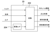
- FIG. 2 is a block diagram showing the configuration of the realization unit 30.
- the realization unit 30 includes a target combustion A / F setting unit 304.
- the target combustion A / F setting unit 304 has the target value of the combustion A / F as a fixed value.
- the combustion A / F is an important torque influence factor that affects the torque-ignition timing characteristics, but the combustion A / F is not used as a control amount.
- the A / F for the entire cylinder is used as the control amount. Accurate torque control becomes possible by generating the target value of the combustion A / F in the realization unit 30 and using it for calculating the actuator operation amount.
- the realization unit 30 uses the conversion unit 302 to calculate each operation amount.
- the conversion unit 302 is an inverse model of the internal combustion engine according to the present embodiment, and includes a plurality of statistical models and physical models represented by maps and functions.
- the conversion unit 302 receives the target values of the three control amounts of torque, efficiency, and A / F, and the target value of the combustion A / F. Then, four types of operation amounts converted from these target values, that is, the throttle opening, the ignition timing, the fuel injection amount, and the fuel injection timing are output from the conversion unit 302. Note that engine information such as the engine speed is referred to in the conversion process in the conversion unit 302.
- various operations of the control device can be realized by a program that is read into a memory and executed by a control device as a computer.
- This program a Using the three physical quantities of torque, efficiency, and air-fuel ratio as the control quantity of the internal combustion engine, the target value of each control quantity is set by aggregating at least part of the requests related to the function of the internal combustion engine into these three physical quantities.
- Step b Based on the target values of the three control amounts of torque, efficiency, and air-fuel ratio, the three manipulated variables of throttle opening, ignition timing, and fuel injection amount and the distribution of the air-fuel ratio in the cylinder can be adjusted.
- Setting a fuel injection timing as a fourth operation amount that can be performed;
- It consists of codes for performing the step of outputting the set four types of operation amounts to the actuators to be operated.
- This program can be stored in a recording medium such as a ROM and provided in the control device.
- the target value setting unit 20 corresponds to “target value setting means” of the present invention
- the realization unit 30 corresponds to “operation amount setting means” and “operation amount output means” of the present invention. 2 is equivalent to the “operation amount setting means” in the second and third embodiments of the present invention.
- the target value of the combustion A / F is a fixed value
- the target combustion A / F setting unit 304 has the target value of the combustion A / F as a fixed value for each operating state of the internal combustion engine. It may be. According to this, the accuracy of torque control can be improved by realizing the optimum combustion A / F according to the operating state of the internal combustion engine.
- the realization unit 30 having the configuration shown in FIG. 2 corresponds to the “operation amount setting means” according to the second and fourth aspects of the present invention.
- a target correspondence relationship between the A / F in the entire cylinder and the actual combustion A / F is set in advance, and the target combustion A / F setting unit 304 determines the combustion A from the target value of A / F that is the control amount.
- the target value of / F may be determined. According to this, the accuracy of torque control can be improved by realizing the optimum combustion A / F according to the target value of A / F in the entire cylinder.
- the realization unit 30 having the configuration shown in FIG. 2 corresponds to the “operation amount setting means” according to the second and fifth aspects of the present invention.
- Embodiment 2 FIG. Next, a second embodiment of the present invention will be described with reference to FIGS.
- FIG. 1 The overall configuration of the control device of the present embodiment is shown in the block diagram of FIG. 1 as in the first embodiment.
- the difference between the control device of the present embodiment and the control device of the first embodiment is in the configuration and function of the realization unit 30 which is one element constituting the control device.
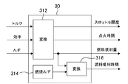
- FIG. 3 is a block diagram showing the configuration of the realization unit 30 according to this exemplary embodiment.
- the realization unit 30 includes a conversion unit 312, a conversion unit 316, and a target combustion A / F setting unit 314.
- the conversion unit 302 corresponds to an inverse model of the internal combustion engine.
- the conversion unit 312 and the conversion unit 316 constitute an inverse model of the internal combustion engine.
- the target combustion A / F setting unit 314 has a target value of the combustion A / F as a fixed value.
- the realization unit 30 first calculates the three operation amounts of the throttle opening, the ignition timing, and the fuel injection amount by the conversion unit 312 among the necessary four operation amounts.
- the conversion unit 312 receives the target values for the three control amounts of torque, efficiency, and A / F. Then, the three types of operation amounts converted from these target values are output from the conversion unit 312.
- the remaining operation amount, that is, the fuel injection timing is calculated by the conversion unit 316.
- the conversion unit 316 receives the fuel injection amount calculated by the conversion unit 312 and the target value of the combustion A / F. Then, the fuel injection timing converted from the fuel injection amount and the target value of the combustion A / F is output from the conversion unit 316.
- engine information such as engine speed is referred to in the conversion processing in each of the conversion units 312 and 316.
- each operation amount is calculated according to the procedure shown in the flowchart of FIG.
- various requests relating to the function of the internal combustion engine such as drivability, exhaust gas or fuel consumption, are collected into three control amounts of torque, efficiency and A / F. This process is performed by the target value setting unit 20.
- the three control amounts are converted into throttle opening (TA), ignition timing (SA), and fuel injection amount. This process is performed by the conversion unit 312 which is an element of the implementation unit 30.
- step S130 fuel injection is performed based on engine information such as the target value of combustion A / F set by the target combustion A / F setting unit 314, the fuel injection amount calculated by the conversion unit 312 and the engine speed.
- the time is derived.
- This processing is performed by the conversion unit 316 that is an element of the implementation unit 30.
- the operation amounts calculated by the realization unit 30, that is, the throttle opening (TA), the ignition timing (SA), the fuel injection amount, and the fuel injection timing are set in the actuators 2, 4, and 6.
- the control device performs the calculation of the throttle opening, the ignition timing and the fuel injection amount separately from the calculation of the fuel injection timing.
- each target value of the controlled variable is converted into four types including the fuel injection timing, while avoiding complication of calculation processing necessary for conversion of the controlled variable into the manipulated variable. It is possible to accurately reflect the amount of operation.
- the target value of the combustion A / F is a fixed value
- the target combustion A / F setting unit 314 has the target value of the combustion A / F as a fixed value for each operating state of the internal combustion engine. It may be. Or you may make it determine the target value of combustion A / F from the target value of A / F which is control amount.
- Embodiment 3 FIG. Next, a third embodiment of the present invention will be described with reference to FIGS.
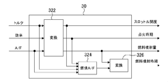
- FIG. 5 is a block diagram showing the configuration of the realizing unit 30 according to the present embodiment.
- the realization unit 30 includes a conversion unit 322, a conversion unit 326, and a target combustion A / F setting unit 324.
- the conversion unit 302 corresponds to the inverse model of the internal combustion engine.
- the conversion unit 322, the conversion unit 326, and the target combustion A / F setting unit 324 are all included in the internal combustion engine.
- An inverse model is constructed.
- the realization unit 30 first calculates three types of operation amounts of the throttle opening, the ignition timing, and the fuel injection amount among the necessary four types of operation amounts by the conversion unit 322. Each target value of the three types of control amounts of torque, efficiency, and A / F is input to the conversion unit 322. Then, the three types of operation amounts converted from these target values are output from the conversion unit 322. The remaining operation amount, that is, the fuel injection timing is calculated by the conversion unit 326.
- the conversion unit 326 receives the fuel injection amount calculated by the conversion unit 322 and the target value of the combustion A / F. The fuel injection timing converted from the fuel injection amount and the target value of the combustion A / F is output from the conversion unit 326.
- engine information such as engine speed is referred to in the conversion processing in each of the conversion units 322 and 326.
- the target value of the combustion A / F is a variable.
- the target combustion A / F setting unit 324 receives torque and A / F as control amounts, and throttle opening and ignition timing as operation amounts.
- the target combustion A / F setting unit 324 calculates a target value for the combustion A / F from these input values.
- the target combustion A / F setting unit 324 has a torque-ignition timing characteristic map as shown in FIG. This map is prepared for each torque influence factor (other than the ignition timing and fuel injection timing) such as the intake air amount and A / F.
- the target combustion A / F setting unit 324 first calculates the intake air amount from the throttle opening, and selects a torque-ignition timing characteristic map based on the intake air amount, A / F, and the like. As shown in FIG. 6, a plurality of torque-ignition timing characteristic curves are set in each map. These torque-ignition timing characteristic curves are set for each combustion A / F. This is because if the actual combustion A / F is different, the combustion speed is also different, and as a result, the torque-ignition timing characteristics are different.
- the target combustion A / F setting unit 324 specifies a torque-ignition timing characteristic curve capable of realizing both the desired torque Tk and the desired ignition timing SAk in the selected map. Then, the combustion A / F at which the specified torque-ignition timing characteristic curve is obtained is set as the target value of the combustion A / F.
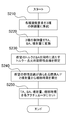
- each operation amount is calculated according to the procedure shown in the flowchart of FIG.
- various requirements relating to the function of the internal combustion engine such as drivability, exhaust gas, or fuel consumption, are collected into three control amounts of torque, efficiency, and A / F. This process is performed by the target value setting unit 20.
- the three control amounts are converted into throttle opening (TA), ignition timing (SA), and fuel injection amount. This process is performed by the conversion unit 322, which is an element of the implementation unit 30.
- a torque-ignition timing characteristic curve that satisfies the desired torque and the ignition timing at the same time is specified using the map shown in FIG.
- the combustion A / F at which the specified torque-ignition timing characteristic curve is obtained is set as the target value of the combustion A / F.
- the fuel injection timing is derived from the target value of the combustion A / F set by the target combustion A / F setting unit 324 and the fuel injection amount calculated by the conversion unit 322. This process is performed by the conversion unit 326, which is an element of the implementation unit 30.
- step S250 the operation amounts calculated by the realization unit 30, that is, the throttle opening (TA), the ignition timing (SA), the fuel injection amount, and the fuel injection timing are set in the actuators 2, 4, and 6.
- the control device of the present embodiment first determines the throttle opening, the ignition timing, and the fuel injection amount from the target values of the three types of control amounts.
- the throttle opening By determining the throttle opening, the intake air amount is determined, and the A / F of the entire cylinder, which is one of the control amounts, is determined from the intake air amount and the fuel injection amount. Further, the efficiency which is one of the control amounts is determined by the ignition timing.
- the torque which is the remaining control amount, depends on the actual combustion A / F.
- the control device of the present embodiment specifies a torque-ignition timing characteristic curve corresponding to a desired torque and ignition timing, and sets the combustion A / F that can obtain the characteristic curve as a target value of the combustion A / F. .
- the three control amounts of torque, efficiency and A / F are determined based on the previously determined three operation amounts.
- Each target value can be realized. That is, according to the control device of the present embodiment, the three control amounts of torque, efficiency, and A / F can be made to follow each target value with high accuracy simultaneously under any operating condition.
- the realization unit 30 having the configuration shown in FIG. 5 corresponds to the “operation amount setting means” according to the sixth and seventh aspects of the present invention.
- the map shown in FIG. 6 does not consider the difference in the actual air-fuel mixture amount.
- the target value of the combustion A / F is set with higher accuracy, it may be made into a three-dimensional map that takes into account the influence of the actual air-fuel mixture amount.
- the target value of the combustion A / F derived from the map shown in FIG. 6 may be corrected using a map or coefficient that has been obtained in advance through experiments or the like.
- FIG. A fourth embodiment of the present invention will be described with reference to FIGS.
- the internal combustion engine according to the present embodiment is an internal combustion engine that performs operation by stratified combustion.
- a throttle 2 as an intake air amount adjustment valve
- an ignition device 4 for adjusting ignition timing
- a fuel injection device 6 for directly injecting fuel into the cylinder
- a swirl flow in the cylinder A swirl control valve (hereinafter referred to as SCV) 8 is provided.
- control device of the present embodiment is configured as shown in the block diagram of FIG. In FIG. 8, each element of the control device is indicated by a block, and signal transmission (main) between the blocks is indicated by an arrow.
- signal transmission (main) between the blocks is indicated by an arrow.
- the control device is roughly composed of three parts 10, 20, and 40.
- the function request generator 10 is positioned at the top.
- a target value setting unit 20 is provided below the function request generation unit 10, and an implementation unit 40 is provided below that.
- Each of the actuators 2, 4, 6, 8 is connected to the realization unit 40.
- Each configuration of the function request generation unit 10 and the target value setting unit 20 and the contents of the processing performed there are the same as those according to the first embodiment. Below, the structure of the implementation
- the realization part 40 is the operation amount of each actuator 2, 4, 6, 8 required in order to implement
- the operation amount calculated by the realization unit 40 includes the throttle opening for operating the throttle 2, the ignition timing for operating the ignition device 4, the fuel injection amount for operating the fuel injection device 6, and the SCV8. SCV opening for operation.
- the fuel injection timing is also an operation amount, in this embodiment, it is not included in the operation amount calculated from the three control amounts of torque, efficiency, and A / F.
- the fuel injection timing is set to a predetermined timing suitable for realizing stratified combustion.
- the SCV opening is used as the manipulated variable in addition to the throttle opening, the ignition timing, and the fuel injection amount.
- the swirl flow in the cylinder can be adjusted by manipulating the SCV opening. If the swirl flow changes, the transport speed when the dense A / F gas mass generated by the fuel injection reaches the vicinity of the spark plug also changes. Therefore, by using the SCV opening as one of the manipulated variables, the A / F in the vicinity of the spark plug, that is, the actual combustion A / F can be adjusted separately from the A / F in the entire cylinder.
- FIG. 9 is a block diagram showing the configuration of the realization unit 40.
- the realization unit 40 includes a target combustion A / F setting unit 404.
- the target combustion A / F setting unit 404 has a target value of the combustion A / F as a fixed value.
- the combustion A / F is an important torque influence factor that affects the torque-ignition timing characteristics, but the combustion A / F is not used as a control amount.
- the A / F for the entire cylinder is used as the control amount. Accurate torque control becomes possible by generating the target value of the combustion A / F in the realization unit 40 and using it for calculating the actuator operation amount.
- the realization unit 40 uses the conversion unit 402 to calculate each operation amount.
- the conversion unit 402 is an inverse model of the internal combustion engine according to the present embodiment, and includes a plurality of statistical models and physical models represented by maps and functions.
- the conversion unit 402 receives the target values of the three control amounts of torque, efficiency, and A / F and the target value of the combustion A / F. Then, four types of operation amounts converted from these target values, that is, the throttle opening, the ignition timing, the fuel injection amount, and the SCV opening are output from the conversion unit 402. It should be noted that engine information such as engine speed and fuel injection timing is referred to for conversion processing in the conversion unit 402.
- the configuration of the realization unit 40 according to the present embodiment may be changed to the configuration shown in the block diagram of FIG. 3 or FIG. A configuration as shown in the block diagram of FIG. However, in that case, what is calculated from the realization unit 40 is not the fuel injection timing but the SCV opening.
- target value setting means “operation amount setting means” and “operation amount output means” according to the present invention are embodied. It is only an example of a configuration that the means can take. All configurations capable of realizing the functions of “target value setting means”, “operation amount setting means”, and “operation amount output means” according to the present invention are included in the scope of each means.
- the throttle is used as the intake air amount adjustment valve in the above-described embodiment
- an intake valve with a variable mechanism that can continuously convert the lift amount or the operating angle may be used. In this case, the lift amount or the operating angle becomes the operation amount of the intake air amount adjustment valve.
- the “fourth operation amount” according to the present invention is not limited to the fuel injection timing and the SCV opening as long as the operation amount can adjust the air-fuel ratio distribution in the cylinder.
- the valve opening degree can be used as the fourth operation amount.
- the valve timing of the intake valve adjusted by the valve timing variable mechanism can also be used as the fourth operation amount. According to these manipulated variables, similarly to the SCV opening, the transport speed when a rich air-fuel ratio gas mass reaches the vicinity of the spark plug can be adjusted.
- control device and method of the internal combustion engine of the present invention is an internal combustion engine in which the A / F in the vicinity of the spark plug and the A / F in the entire cylinder are different.
- Such an internal combustion engine includes an internal combustion engine that burns with intentionally non-uniform A / F distribution in the cylinder, but the operation by stratified combustion according to the above-described embodiments is merely one example. Moreover, even if the internal combustion engine performs homogeneous combustion, an internal combustion engine that results in non-uniformity in the in-cylinder A / F distribution depending on the operating state is included in the control object of the present invention.
- the A / F distribution in the cylinder may be uneven, and it is not always true that the A / F in the vicinity of the spark plug matches the A / F in the entire cylinder. Absent. Since the A / F in the vicinity of the spark plug affects the torque-ignition timing characteristics, the accuracy of the torque control can be improved by adjusting the A / F distribution in the cylinder by the fourth operation amount.
Landscapes
- Engineering & Computer Science (AREA)
- Chemical & Material Sciences (AREA)
- Combustion & Propulsion (AREA)
- Mechanical Engineering (AREA)
- General Engineering & Computer Science (AREA)
- Combined Controls Of Internal Combustion Engines (AREA)
- Electrical Control Of Ignition Timing (AREA)
- Electrical Control Of Air Or Fuel Supplied To Internal-Combustion Engine (AREA)
- Output Control And Ontrol Of Special Type Engine (AREA)
Abstract
Description
4 点火装置
6 燃料噴射装置
8 スワールコントロールバルブ
10 機能要求発生部
12,14,16 要求出力要素
20 目標値設定部
22 トルク調停要素
24 効率調停要素
26 A/F調停要素
30 実現部
40 実現部
302 変換部
304 目標燃焼A/F設定部
312 変換部
314 目標燃焼A/F設定部
316 変換部
322 変換部
324 目標燃焼A/F設定部
326 変換部
402 変換部
404 目標燃焼A/F設定部
本発明の実施の形態1について図1及び図2を用いて説明する。
a.トルク、効率及び空燃比の3種の物理量を内燃機関の制御量として用い、内燃機関の機能に関する要求の少なくとも一部をこれら3種の物理量に集約することよって各制御量の目標値を設定するステップ
b.トルク、効率及び空燃比の3種の制御量の各目標値に基づいて、スロットル開度、点火時期及び燃料噴射量の3種の操作量と、筒内の空燃比の分布を調整することができる第4の操作量としての燃料噴射時期を設定するステップ
c.設定した4種の操作量をそれぞれ操作対象となるアクチュエータへ出力するステップ
を行うためのコードから構成されている。このプログラムはROM等の記録媒体に格納して制御装置に備えることができる。
次に、本発明の実施の形態2について図1,図3及び図4を用いて説明する。
次に、本発明の実施の形態3について図1,図5乃至図7を用いて説明する。
本発明の実施の形態4について図8及び図9を用いて説明する。
本発明は上述の実施の形態には限定されない。上述の実施の形態には、本発明にかかる「目標値設定手段」や「操作量設定手段」や「操作量出力手段」が具現化されているが、そこに開示されている構成はこれらの手段が採り得る構成の一例にすぎない。本発明にかかる「目標値設定手段」や「操作量設定手段」や「操作量出力手段」の機能を実現することが可能な全ての構成がそれら各手段の範囲に含まれる。
Claims (16)
- 点火プラグ近傍の空燃比と筒内全体の空燃比とが異なる内燃機関の制御装置であって、前記内燃機関を複数のアクチュエータの操作によって制御する制御装置において、
トルク、効率及び空燃比の3種の物理量を前記内燃機関の制御量として用い、前記内燃機関の機能に関する要求の少なくとも一部を前記3種の物理量に集約することによって各制御量の目標値を設定する目標値設定手段と、
トルク、効率及び空燃比の3種の制御量の各目標値に基づいて、吸気量調整弁の開度、点火時期及び燃料噴射量の3種の操作量と、筒内の空燃比分布を調整することができる第4の操作量とを設定する操作量設定手段と、
設定した前記4種の操作量をそれぞれ操作対象となるアクチュエータへ出力する操作量出力手段と、
を備えることを特徴とする内燃機関の制御装置。 - 前記操作量設定手段は、所定の規則に従って点火プラグ近傍の空燃比の目標値を生成し、前記3種の制御量の各目標値と生成した点火プラグ近傍の空燃比の目標値とから各操作量を算出することを特徴とする請求項1記載の内燃機関の制御装置。
- 前記操作量設定手段は、点火プラグ近傍の空燃比の目標値を固定値として持っていることを特徴とする請求項2記載の内燃機関の制御装置。
- 前記操作量設定手段は、点火プラグ近傍の空燃比の目標値を前記内燃機関の運転状態毎に固定値として持っていることを特徴とする請求項3記載の内燃機関の制御装置。
- 前記操作量設定手段は、予め設定された筒内全体の空燃比と点火プラグ近傍の空燃比との目標対応関係に基づき、制御量である空燃比の目標値から点火プラグ近傍の空燃比の目標値を決定することを特徴とする請求項2記載の内燃機関の制御装置。
- 前記操作量設定手段は、前記3種の制御量の各目標値に基づいて吸気量調整弁の開度、点火時期及び燃料噴射量の3種の操作量を算出し、前記3種の操作量のもとで前記3種の制御量の各目標値を実現するために必要な燃焼空燃比を点火プラグ近傍の空燃比の目標値として算出することを特徴とする請求項2記載の内燃機関の制御装置。
- 前記操作量設定手段は、前記3種の制御量の各目標値に基づいて吸気量調整弁の開度、点火時期及び燃料噴射量を算出し、燃料噴射量と点火プラグ近傍の空燃比の目標値とから前記第4の操作量を算出することを特徴とする請求項2乃至6の何れか1項に記載の内燃機関の制御装置。
- 前記操作量設定手段は、前記第4の操作量として燃料噴射時期を設定することを特徴とする請求項1乃至7の何れか1項に記載の内燃機関の制御装置。
- 点火プラグ近傍の空燃比と筒内全体の空燃比とが異なる内燃機関を複数のアクチュエータの操作によって制御する方法であって、
トルク、効率及び空燃比の3種の物理量を前記内燃機関の制御量として用い、前記内燃機関の機能に関する要求の少なくとも一部を前記3種の物理量に集約することよって各制御量の目標値を設定するステップと、
トルク、効率及び空燃比の3種の制御量の各目標値に基づいて、吸気量調整弁の開度、点火時期及び燃料噴射量の3種の操作量と、筒内の空燃比の分布を調整することができる第4の操作量とを設定するステップと、
設定した前記4種の操作量をそれぞれ操作対象となるアクチュエータへ出力するステップと、
を実行することを特徴とする内燃機関の制御方法。 - 前記の操作量を設定するステップでは、所定の規則に従って点火プラグ近傍の空燃比の目標値を生成し、前記3種の制御量の各目標値と生成した点火プラグ近傍の空燃比の目標値とから各操作量を算出することを特徴とする請求項9記載の内燃機関の制御方法。
- 前記の操作量を設定するステップでは、点火プラグ近傍の空燃比の目標値として予め容易された固定値を使用することを特徴とする請求項10記載の内燃機関の制御方法。
- 前記の操作量を設定するステップでは、点火プラグ近傍の空燃比の目標値として前記内燃機関の運転状態毎に予め用意された固定値を使用することを特徴とする請求項11記載の内燃機関の制御方法。
- 前記の操作量を設定するステップでは、予め設定された筒内全体の空燃比と点火プラグ近傍の空燃比との目標対応関係に基づき、制御量である空燃比の目標値から点火プラグ近傍の空燃比の目標値を決定することを特徴とする請求項10記載の内燃機関の制御方法。
- 前記の操作量を設定するステップでは、前記3種の制御量の各目標値に基づいて吸気量調整弁の開度、点火時期及び燃料噴射量の3種の操作量を算出し、前記3種の操作量のもとで前記3種の制御量の各目標値を実現するために必要な燃焼空燃比を点火プラグ近傍の空燃比の目標値として算出することを特徴とする請求項2記載の内燃機関の制御方法。
- 前記の操作量を設定するステップでは、前記3種の制御量の各目標値に基づいて吸気量調整弁の開度、点火時期及び燃料噴射量を算出し、燃料噴射量と点火プラグ近傍の空燃比の目標値とから前記第4の操作量を算出することを特徴とする請求項10乃至14の何れか1項に記載の内燃機関の制御方法。
- 前記の操作量を設定するステップでは、前記第4の操作量として燃料噴射時期を設定することを特徴とする請求項9乃至15の何れか1項に記載の内燃機関の制御方法。
Priority Applications (7)
| Application Number | Priority Date | Filing Date | Title |
|---|---|---|---|
| PCT/JP2008/068650 WO2010044148A1 (ja) | 2008-10-15 | 2008-10-15 | 内燃機関の制御装置 |
| EP08876720.7A EP2336530B1 (en) | 2008-10-15 | 2008-10-15 | Control device for internal combustion engine |
| KR1020127012962A KR20120073344A (ko) | 2008-10-15 | 2008-10-15 | 내연 기관의 제어 장치 |
| US12/672,375 US9163578B2 (en) | 2008-10-15 | 2008-10-15 | Control device for internal combustion engine |
| KR1020107003711A KR101266764B1 (ko) | 2008-10-15 | 2008-10-15 | 내연 기관의 제어 장치 |
| CN2008801025367A CN101779027B (zh) | 2008-10-15 | 2008-10-15 | 内燃机的控制装置 |
| JP2010504343A JP4905588B2 (ja) | 2008-10-15 | 2008-10-15 | 内燃機関の制御装置 |
Applications Claiming Priority (1)
| Application Number | Priority Date | Filing Date | Title |
|---|---|---|---|
| PCT/JP2008/068650 WO2010044148A1 (ja) | 2008-10-15 | 2008-10-15 | 内燃機関の制御装置 |
Publications (1)
| Publication Number | Publication Date |
|---|---|
| WO2010044148A1 true WO2010044148A1 (ja) | 2010-04-22 |
Family
ID=42106326
Family Applications (1)
| Application Number | Title | Priority Date | Filing Date |
|---|---|---|---|
| PCT/JP2008/068650 WO2010044148A1 (ja) | 2008-10-15 | 2008-10-15 | 内燃機関の制御装置 |
Country Status (6)
| Country | Link |
|---|---|
| US (1) | US9163578B2 (ja) |
| EP (1) | EP2336530B1 (ja) |
| JP (1) | JP4905588B2 (ja) |
| KR (2) | KR101266764B1 (ja) |
| CN (1) | CN101779027B (ja) |
| WO (1) | WO2010044148A1 (ja) |
Cited By (1)
| Publication number | Priority date | Publication date | Assignee | Title |
|---|---|---|---|---|
| EP2565433A1 (en) * | 2010-04-27 | 2013-03-06 | Toyota Jidosha Kabushiki Kaisha | Control device for internal combustion engine |
Families Citing this family (7)
| Publication number | Priority date | Publication date | Assignee | Title |
|---|---|---|---|---|
| JP4832542B2 (ja) * | 2009-03-18 | 2011-12-07 | 本田技研工業株式会社 | 内燃機関の制御装置 |
| WO2012042610A1 (ja) * | 2010-09-29 | 2012-04-05 | トヨタ自動車株式会社 | 内燃機関の制御装置 |
| JP5786880B2 (ja) * | 2013-03-14 | 2015-09-30 | トヨタ自動車株式会社 | 内燃機関の制御装置 |
| JP5811128B2 (ja) | 2013-03-29 | 2015-11-11 | トヨタ自動車株式会社 | 内燃機関の制御装置 |
| KR102478116B1 (ko) * | 2016-06-21 | 2022-12-16 | 현대자동차주식회사 | 차량의 공연비 제어방법 |
| JP2020012431A (ja) * | 2018-07-19 | 2020-01-23 | トヨタ自動車株式会社 | 内燃機関の制御装置 |
| CN114876656B (zh) * | 2022-04-18 | 2023-04-25 | 东风柳州汽车有限公司 | 改善动力不足的控制方法、装置、设备及存储介质 |
Citations (4)
| Publication number | Priority date | Publication date | Assignee | Title |
|---|---|---|---|---|
| JP2000310135A (ja) * | 1999-04-28 | 2000-11-07 | Honda Motor Co Ltd | 内燃機関の空燃比制御装置 |
| JP2002332886A (ja) * | 2001-05-01 | 2002-11-22 | Toyota Motor Corp | 内燃機関の燃料噴射制御装置 |
| JP2003301766A (ja) * | 2002-04-09 | 2003-10-24 | Denso Corp | 内燃機関のトルク制御装置 |
| JP2008231986A (ja) * | 2007-03-19 | 2008-10-02 | Toyota Motor Corp | トルクディマンド型の内燃機関の制御装置 |
Family Cites Families (15)
| Publication number | Priority date | Publication date | Assignee | Title |
|---|---|---|---|---|
| JPS60163731A (ja) * | 1984-02-07 | 1985-08-26 | Nissan Motor Co Ltd | 車速制御装置 |
| JP3030226B2 (ja) * | 1995-03-27 | 2000-04-10 | マツダ株式会社 | 自動車用リーンバーンエンジン |
| DE19612150A1 (de) | 1996-03-27 | 1997-10-02 | Bosch Gmbh Robert | Steuereinrichtung für eine Benzin-Brennkraftmaschine mit Direkteinspritzung |
| JP3695493B2 (ja) * | 1996-11-12 | 2005-09-14 | 三菱自動車工業株式会社 | 筒内噴射内燃機関の制御装置 |
| JP3233039B2 (ja) * | 1996-08-28 | 2001-11-26 | 三菱自動車工業株式会社 | 筒内噴射型火花点火式内燃エンジンの制御装置 |
| JPH11182299A (ja) * | 1997-12-15 | 1999-07-06 | Nissan Motor Co Ltd | エンジンのトルク制御装置 |
| JPH11343911A (ja) * | 1998-03-31 | 1999-12-14 | Mazda Motor Corp | 筒内噴射式エンジンの燃料制御装置 |
| JP3911912B2 (ja) * | 1999-06-23 | 2007-05-09 | 株式会社日立製作所 | エンジン制御システム及び制御方法 |
| US6497212B2 (en) * | 2000-02-10 | 2002-12-24 | Denso Corporation | Control apparatus for a cylinder injection type internal combustion engine capable of suppressing undesirable torque shock |
| JP4253986B2 (ja) * | 2000-03-03 | 2009-04-15 | マツダ株式会社 | 筒内噴射式エンジンの制御装置 |
| EP1199469B1 (en) * | 2000-10-20 | 2010-01-06 | Nissan Motor Company, Limited | Enhanced engine response to torque demand during cold-start and catalyst warm-up |
| JP2002339789A (ja) * | 2001-05-16 | 2002-11-27 | Mazda Motor Corp | 火花点火式直噴エンジンの制御装置および燃料噴射時期設定方法 |
| JP2003222039A (ja) * | 2002-01-30 | 2003-08-08 | Mazda Motor Corp | エンジンの制御装置 |
| EP1431555B1 (en) * | 2002-12-20 | 2014-01-22 | Honda Motor Co., Ltd. | Control system and method for internal combustion engine |
| US6912989B2 (en) * | 2003-04-30 | 2005-07-05 | Nissan Motor Co., Ltd. | Fuel injection control device for a direct fuel injection engine |
-
2008
- 2008-10-15 WO PCT/JP2008/068650 patent/WO2010044148A1/ja active Application Filing
- 2008-10-15 JP JP2010504343A patent/JP4905588B2/ja not_active Expired - Fee Related
- 2008-10-15 EP EP08876720.7A patent/EP2336530B1/en not_active Not-in-force
- 2008-10-15 KR KR1020107003711A patent/KR101266764B1/ko active IP Right Grant
- 2008-10-15 US US12/672,375 patent/US9163578B2/en not_active Expired - Fee Related
- 2008-10-15 CN CN2008801025367A patent/CN101779027B/zh not_active Expired - Fee Related
- 2008-10-15 KR KR1020127012962A patent/KR20120073344A/ko not_active Application Discontinuation
Patent Citations (4)
| Publication number | Priority date | Publication date | Assignee | Title |
|---|---|---|---|---|
| JP2000310135A (ja) * | 1999-04-28 | 2000-11-07 | Honda Motor Co Ltd | 内燃機関の空燃比制御装置 |
| JP2002332886A (ja) * | 2001-05-01 | 2002-11-22 | Toyota Motor Corp | 内燃機関の燃料噴射制御装置 |
| JP2003301766A (ja) * | 2002-04-09 | 2003-10-24 | Denso Corp | 内燃機関のトルク制御装置 |
| JP2008231986A (ja) * | 2007-03-19 | 2008-10-02 | Toyota Motor Corp | トルクディマンド型の内燃機関の制御装置 |
Non-Patent Citations (1)
| Title |
|---|
| See also references of EP2336530A4 * |
Cited By (2)
| Publication number | Priority date | Publication date | Assignee | Title |
|---|---|---|---|---|
| EP2565433A1 (en) * | 2010-04-27 | 2013-03-06 | Toyota Jidosha Kabushiki Kaisha | Control device for internal combustion engine |
| EP2565433A4 (en) * | 2010-04-27 | 2013-04-17 | Toyota Motor Co Ltd | CONTROL DEVICE FOR INTERNAL COMBUSTION ENGINE |
Also Published As
| Publication number | Publication date |
|---|---|
| EP2336530A1 (en) | 2011-06-22 |
| EP2336530A4 (en) | 2015-07-29 |
| CN101779027A (zh) | 2010-07-14 |
| US20110098905A1 (en) | 2011-04-28 |
| KR101266764B1 (ko) | 2013-05-28 |
| KR20100083123A (ko) | 2010-07-21 |
| EP2336530B1 (en) | 2018-11-21 |
| JP4905588B2 (ja) | 2012-03-28 |
| JPWO2010044148A1 (ja) | 2012-03-08 |
| US9163578B2 (en) | 2015-10-20 |
| KR20120073344A (ko) | 2012-07-04 |
| CN101779027B (zh) | 2013-12-11 |
Similar Documents
| Publication | Publication Date | Title |
|---|---|---|
| JP4905588B2 (ja) | 内燃機関の制御装置 | |
| RU2451809C1 (ru) | Устройство управления для двигателя внутреннего сгорания | |
| JP4893553B2 (ja) | 内燃機関の制御装置 | |
| JP6041050B2 (ja) | 内燃機関の制御装置 | |
| JP2009019504A (ja) | エンジンの制御方法並びに制御装置 | |
| US9976497B2 (en) | Control device for internal combustion engine | |
| JP4453091B2 (ja) | エンジンの制御装置 | |
| JP7359011B2 (ja) | 内燃機関の制御装置 | |
| JP5278606B2 (ja) | 内燃機関の制御装置 | |
| KR101262198B1 (ko) | 작동 모드를 변화시킬 때 내연기관을 제어하기 위한 방법및 장치 | |
| JP5644733B2 (ja) | エンジンの制御装置 | |
| JP5708812B2 (ja) | 内燃機関の制御装置 | |
| JP2010223122A (ja) | 内燃機関の制御装置 | |
| JP3931708B2 (ja) | 内燃機関のトルク制御装置 | |
| JP2004286037A (ja) | 内燃機関の燃料噴射制御装置 | |
| JP2015117604A (ja) | 内燃機関の制御装置 | |
| JP2007270663A (ja) | 内燃機関の特性パラメータの定常値を求める方法 | |
| JP2002227682A (ja) | 内燃機関の燃料噴射制御装置 | |
| JP2017194062A (ja) | 内燃機関を駆動するための方法及び装置 |
Legal Events
| Date | Code | Title | Description |
|---|---|---|---|
| WWE | Wipo information: entry into national phase |
Ref document number: 200880102536.7 Country of ref document: CN |
|
| WWE | Wipo information: entry into national phase |
Ref document number: 2010504343 Country of ref document: JP |
|
| WWE | Wipo information: entry into national phase |
Ref document number: 2008876720 Country of ref document: EP |
|
| ENP | Entry into the national phase |
Ref document number: 20107003711 Country of ref document: KR Kind code of ref document: A |
|
| 121 | Ep: the epo has been informed by wipo that ep was designated in this application |
Ref document number: 08876720 Country of ref document: EP Kind code of ref document: A1 |
|
| WWE | Wipo information: entry into national phase |
Ref document number: 12672375 Country of ref document: US |
|
| NENP | Non-entry into the national phase |
Ref country code: DE |