WO2010029974A1 - インクジェットヘッドおよびインクジェットヘッド装置 - Google Patents
インクジェットヘッドおよびインクジェットヘッド装置 Download PDFInfo
- Publication number
- WO2010029974A1 WO2010029974A1 PCT/JP2009/065854 JP2009065854W WO2010029974A1 WO 2010029974 A1 WO2010029974 A1 WO 2010029974A1 JP 2009065854 W JP2009065854 W JP 2009065854W WO 2010029974 A1 WO2010029974 A1 WO 2010029974A1
- Authority
- WO
- WIPO (PCT)
- Prior art keywords
- ink
- groove
- inkjet head
- common ink
- ink groove
- Prior art date
- Legal status (The legal status is an assumption and is not a legal conclusion. Google has not performed a legal analysis and makes no representation as to the accuracy of the status listed.)
- Ceased
Links
Images











Classifications
-
- B—PERFORMING OPERATIONS; TRANSPORTING
- B41—PRINTING; LINING MACHINES; TYPEWRITERS; STAMPS
- B41J—TYPEWRITERS; SELECTIVE PRINTING MECHANISMS, i.e. MECHANISMS PRINTING OTHERWISE THAN FROM A FORME; CORRECTION OF TYPOGRAPHICAL ERRORS
- B41J2/00—Typewriters or selective printing mechanisms characterised by the printing or marking process for which they are designed
- B41J2/005—Typewriters or selective printing mechanisms characterised by the printing or marking process for which they are designed characterised by bringing liquid or particles selectively into contact with a printing material
- B41J2/01—Ink jet
- B41J2/135—Nozzles
- B41J2/14—Structure thereof only for on-demand ink jet heads
- B41J2/14201—Structure of print heads with piezoelectric elements
- B41J2/14209—Structure of print heads with piezoelectric elements of finger type, chamber walls consisting integrally of piezoelectric material
-
- B—PERFORMING OPERATIONS; TRANSPORTING
- B41—PRINTING; LINING MACHINES; TYPEWRITERS; STAMPS
- B41J—TYPEWRITERS; SELECTIVE PRINTING MECHANISMS, i.e. MECHANISMS PRINTING OTHERWISE THAN FROM A FORME; CORRECTION OF TYPOGRAPHICAL ERRORS
- B41J2/00—Typewriters or selective printing mechanisms characterised by the printing or marking process for which they are designed
- B41J2/005—Typewriters or selective printing mechanisms characterised by the printing or marking process for which they are designed characterised by bringing liquid or particles selectively into contact with a printing material
- B41J2/01—Ink jet
- B41J2/135—Nozzles
- B41J2/14—Structure thereof only for on-demand ink jet heads
- B41J2002/14419—Manifold
-
- B—PERFORMING OPERATIONS; TRANSPORTING
- B41—PRINTING; LINING MACHINES; TYPEWRITERS; STAMPS
- B41J—TYPEWRITERS; SELECTIVE PRINTING MECHANISMS, i.e. MECHANISMS PRINTING OTHERWISE THAN FROM A FORME; CORRECTION OF TYPOGRAPHICAL ERRORS
- B41J2202/00—Embodiments of or processes related to ink-jet or thermal heads
- B41J2202/01—Embodiments of or processes related to ink-jet heads
- B41J2202/07—Embodiments of or processes related to ink-jet heads dealing with air bubbles
-
- B—PERFORMING OPERATIONS; TRANSPORTING
- B41—PRINTING; LINING MACHINES; TYPEWRITERS; STAMPS
- B41J—TYPEWRITERS; SELECTIVE PRINTING MECHANISMS, i.e. MECHANISMS PRINTING OTHERWISE THAN FROM A FORME; CORRECTION OF TYPOGRAPHICAL ERRORS
- B41J2202/00—Embodiments of or processes related to ink-jet or thermal heads
- B41J2202/01—Embodiments of or processes related to ink-jet heads
- B41J2202/11—Embodiments of or processes related to ink-jet heads characterised by specific geometrical characteristics
-
- B—PERFORMING OPERATIONS; TRANSPORTING
- B41—PRINTING; LINING MACHINES; TYPEWRITERS; STAMPS
- B41J—TYPEWRITERS; SELECTIVE PRINTING MECHANISMS, i.e. MECHANISMS PRINTING OTHERWISE THAN FROM A FORME; CORRECTION OF TYPOGRAPHICAL ERRORS
- B41J2202/00—Embodiments of or processes related to ink-jet or thermal heads
- B41J2202/01—Embodiments of or processes related to ink-jet heads
- B41J2202/12—Embodiments of or processes related to ink-jet heads with ink circulating through the whole print head
Definitions
- the present invention relates to an inkjet head (used in a printer or the like) and an inkjet head device.
- non-impact printing devices such as an ink jet method that can easily cope with colorization and multi-gradation are rapidly spreading in place of impact printing devices in printers.
- an ink jet head as an ink ejecting apparatus used for this, a drop-on-demand type in which only ink droplets necessary for printing are ejected is attracting attention because of its excellent ejection efficiency and ease of cost reduction. Yes.
- the drop-on-demand type is mainly the Kayser method or the thermal jet method.
- the Kaiser method has a drawback that it is difficult to reduce the size and is not suitable for high density.
- the thermal jet method is suitable for increasing the density, the ink is heated with a heater to generate bubbles in the ink and ejected using the energy of the bubbles.
- the heat resistance of the ink is required, and it is difficult to extend the life of the heater, and the energy efficiency is poor, so that the power consumption increases.
- an ink jet method using shear mode deformation of a piezoelectric material uses an electrode formed on both sides of an ink channel wall made of piezoelectric material (hereinafter referred to as “channel wall”) to generate an electric field in a direction perpendicular to the polarization direction of the piezoelectric material.
- the channel wall is deformed in the share mode, and ink droplets are ejected by utilizing the pressure wave fluctuation generated at that time, which is suitable for increasing the density of the nozzles, reducing the power consumption, and increasing the driving frequency.
- ink jet heads utilizing this shear mode deformation for industrial purposes has become active.
- wiring is drawn by discharging a conductive material as ink
- a color filter is manufactured by discharging inks of R, G, and B colors, or thermosetting or ultraviolet (UV) curable ink.
- UV ultraviolet
- inks are used.
- highly volatile ink containing an organic solvent strongly acidic / strongly alkaline ink, ink containing pigments and resin components, ink containing fine particles such as beads, and ink combining these. It is done.
- ink containing fine particles such as beads fine particles are precipitated or floated due to a difference in specific gravity between the ink solvent and the contained fine particles, which may cause uneven distribution of the fine particle concentration in the ink.
- the distribution is biased, the number of fine particles contained in the droplets at the time of ejection varies, resulting in product performance deterioration and defect occurrence.
- Patent Document 1 There is a technique described in International Publication WO95 / 31335 (Patent Document 1) as a technique for circulating and stirring ink to the nearest nozzle hole.
- the pressure generating chamber is a space in which a nozzle plate having nozzle holes on the front side and a diaphragm on the rear side are arranged.
- Two common ink chambers are arranged on both sides of the pressure generation chamber so as to sandwich the pressure generation chamber, and these two common ink chambers communicate with the pressure generation chamber.
- This apparatus has a structure capable of supplying ink from one common ink chamber to the other common ink chamber via a pressure generating chamber.
- FIG. 4 of Patent Document 1 shows the entire recording apparatus including the ink jet head.
- ink is replenished from the ink cartridge to the sub tank via the ink jet head. It is also possible to return the ink to the ink cartridge via the ink jet head by utilizing the water head difference. In the recording apparatus of Patent Document 1, the ink is circulated in this way.
- Patent Document 2 proposes an ink jet head that utilizes shear mode deformation of a piezoelectric material in the wall portion of the groove-shaped pressure generating chamber.
- Patent Document 3 describes an ink jet head having a structure in which a common groove for supplying / discharging ink is processed from the back surface of a substrate.
- One type of inkjet head is a stacked type. This is to assemble the structure of the ink jet head by overlapping each member while aligning them, and an example thereof is described in Japanese Patent Laid-Open No. 6-183029 (Patent Document 4).
- Patent Document 5 a method for circulating and stirring ink to the immediate vicinity of the nozzle hole and eliminating air bubbles is described in Japanese Patent No. 3161095 (Patent Document 5).
- the multilayer ink jet head includes a vibrator unit in which a vibrator is attached to a base, a flow path component member, a diaphragm forming member, a pressure generation chamber, It is composed of five members: a spacer for forming a gap to be formed and a nozzle plate having nozzle holes. These members are assembled by aligning and overlapping each other. In order to achieve high landing accuracy and uniform ejection performance in an inkjet head, the relative positional accuracy of the nozzle hole and the drive unit is extremely important, and the center of the nozzle hole matches the center of the ink path in the drive unit. Must be placed. Therefore, these five members are required to be aligned with high accuracy.
- the ink jet head of Patent Document 4 uses a laminated piezoelectric element in order to ensure the amount of displacement, and the number of parts constituting the ink jet head itself is large. In such a case, it is not suitable for miniaturization and leads to an increase in cost.
- This ink jet head is assembled by housing a piezoelectric substrate having a plurality of grooves in a manifold having an oval recess and covering a nozzle plate having a plurality of nozzle holes.
- the following grooves are formed in the piezoelectric substrate used in the ink jet head of Patent Document 2.
- An electrode is formed on the inner wall of the groove A serving as the pressure generating chamber. When a voltage is applied from the outside, the groove serving as the pressure generating chamber is deformed in the shear mode, and ink is ejected from the nozzle.
- the second groove there is a groove B that is electrically connected to the groove A serving as each pressure generating chamber described above.
- An electrode is also formed on the inner wall of the groove B.
- this R-shaped portion is a portion that is not necessary, but it is generated when the R of the blade is transferred when the dicing machine or the like is processed to connect grooves having different groove depths. Since the radius of the blade is very large with respect to each groove, the area occupied by the R-shaped portion in the piezoelectric substrate is very large, and the presence of the R-shaped portion leads to an increase in size of the piezoelectric substrate.
- the third groove there is a groove C formed so as to be orthogonal to the groove A serving as a pressure generating chamber, and a portion surrounded by the groove C and the nozzle plate is a common ink chamber. Since the common ink chamber serves to supply ink to each pressure generation chamber, the common ink chamber needs to intersect with a plurality of pressure generation chambers. Further, since the common ink chamber needs to supply a sufficient amount of ink, the volume should be sufficiently large. In order to increase the volume of the common ink chamber, there is means for increasing the width of the groove C or increasing the depth. However, if the depth is deeper than the groove A serving as the pressure generating chamber, the grooves A and B Can not be made deeper than the groove A. Therefore, it is necessary to increase the width, but increasing the width of the groove C increases the size of the piezoelectric substrate.
- the piezoelectric substrate necessary for the ink jet head is enlarged in the configuration of Patent Document 2, and the material cost increases because the piezoelectric substrate is expensive.
- the ink jet head described in Patent Document 3 has a structure in which a common groove (common ink chamber) for supplying / discharging ink is processed from the back surface of the substrate.
- a common groove common ink chamber
- the depth of the common ink chamber can be increased. This leads to lowering the flow path resistance of the common ink chamber, and therefore has the advantage that the ink circulation in the ink jet head can be made smoother.
- the region contributing to ink ejection is formed by piezoelectric ceramics.
- the side wall is configured by insulating ceramics. Therefore, when the piezoelectric ceramic that is part of the side wall is deformed to eject ink, both ends of the piezoelectric ceramic on the side wall are bonded to insulating ceramics and the like, so that the deformation is hindered. The discharge efficiency is reduced.
- variations in the thickness of the adhesive also affect variations in deformation of the piezoelectric ceramics. Therefore, it is expected that the discharge characteristics vary for each channel.
- a difference in level may occur due to different processing characteristics between the adhesive portion, the piezoelectric ceramic, and the insulating ceramic. Due to this step, conduction may not be obtained at the time of electrode formation, and there is a problem in reliability.
- Patent Document 5 discloses a method for stirring and excluding bubbles. This patent document 5 is demonstrated using FIG. FIG. 13 shows a state where the nozzle plate 802 provided with the nozzle holes is removed.
- this inkjet head 800 there is a pressure generation chamber 822 between the first reservoir 820 and the second reservoir 821, and ink supply ports 823 and 824 are provided at one ends of the reservoirs 820 and 821, respectively.
- an ink discharge port (not shown) is provided at the other end opposite to one end of the ink supply ports 823 and 824, respectively.
- the cross-sectional areas of the reservoirs 820 and 821 are reduced from the ink supply ports 823 and 824 toward the ink discharge ports (not shown). As a result, even when a pressure loss occurs with respect to the ink flow generated by supplying ink to each pressure generating chamber 822, the cross-sectional area near the ink discharge port is small, so that the flow velocity is not reduced. Ink can be circulated.
- the supply ports 823 and 824 and the discharge port can be circulated while being held at both ends of the open end of the pressure generating chamber 822.
- the supply ports 823 and 824 There is a complicated configuration with a plurality of discharge ports, and there is a problem that the cost including the solenoid valve communicating with each of the discharge ports is high and the maintenance sequence is complicated.
- the ink discharge port and the mixed gas bubble discharge port are made the same, the bubble continues to be mixed up to the ink tank communicating with the discharge port without removing only the bubble mixed in the flow path. As a result, the ink deteriorates due to air bubbles.
- the ink does not actively flow into the pressure generation chambers 822, and most of the ink supply ports 823 and 824.
- the amount of ink ejected is supplied from the first and second reservoirs 820 and 821, but the supply to each pressure generating chamber 822 is not actively performed beyond the amount supplied, so that the ink is discharged. There is a problem that sufficient circulation is not achieved.
- an object of the present invention is to provide an ink jet head and an ink jet head device that can reliably prevent air bubble trapping while preventing ink from staying in the ink groove.
- the inkjet head of the present invention is A piezoelectric substrate having a plurality of individual ink grooves extending in one direction and opening at both ends, and wherein the plurality of individual ink grooves are arranged in parallel in the other direction perpendicular to the one direction;
- the piezoelectric substrate is attached and has a first common ink groove communicating with the plurality of individual ink grooves on one end side of the plurality of individual ink grooves, and the plurality of individual inks on the other end side of the plurality of individual ink grooves.
- a nozzle plate arranged to cover the plurality of individual ink grooves, the first common ink groove and the second common ink groove from above;
- the main body portion communicates with the first common ink groove to supply ink to the first common ink groove, and communicates with the second common ink groove to supply ink from the second common ink groove.
- the nozzle plate has a nozzle hole at a position corresponding to the individual ink groove,
- the bubble discharge port communicating with the first common ink groove is provided so as to be located on the outer side in the other direction with respect to the individual ink groove at the extreme end in the other direction.
- the main body communicates with the first common ink groove and supplies the first common ink groove with ink, and communicates with the second common ink groove.
- a second flow path port for discharging ink from the second common ink groove, so that when ink flows from the first flow path port to the second flow path port, the ink passes other than the individual ink grooves.
- the bubble discharge port communicating with the first common ink groove is provided so as to be located outside the outermost individual ink groove in the other direction. Therefore, air bubbles that try to stay outside the outermost individual ink groove in the first common ink groove can be discharged from the bubble discharge port, and bubble trapping can be reliably prevented.
- the nozzle plate defines a plurality of individual ink chambers together with the plurality of individual ink grooves, defines a first common ink chamber together with the first common ink grooves, and the second.
- a second common ink chamber is defined along with the common ink groove.
- At least one of the bubble discharge ports is formed on the nozzle plate.
- the inkjet head of this embodiment since at least one of the bubble discharge ports is formed in the nozzle plate, a differential pressure generated during maintenance of nozzle clogging is automatically generated in the bubble discharge port. By being applied, it is possible to easily and reliably discharge bubbles from the first common ink chamber without requiring a new maintenance member or the like. Thereby, it is possible to provide an ink jet head which does not cause bubble trapping or ink retention easily and reliably.
- the bubble discharge port is formed on the inner surface of the first common ink groove of the main body.
- the bubble discharge port is formed on the inner surface of the first common ink groove of the main body, so that the nozzle plate is temporarily provided with the bubble discharge port.
- At least one of the bubble discharge ports is formed on a bottom surface of the main body portion facing the nozzle plate in the first common ink groove.
- At least one of the bubble discharge ports is formed on the bottom surface of the main body portion facing the nozzle plate in the first common ink groove.
- At least one of the bubble discharge ports has a circular shape.
- the ink jet head of this embodiment since at least one of the bubble discharge ports has a circular shape, the meniscus is difficult to collapse and is stable, and the air suction phenomenon from the bubble discharge port due to the meniscus breakage or the bubbles Unintentional ink discharge from the discharge port can be prevented.
- ink when ink is not ejected from the ink jet head, it is known to apply a negative pressure to the inside of the ink jet head so that the ink does not sag from the nozzle hole. If too much negative pressure is applied, air is sucked from the nozzle holes, so that an appropriate negative pressure is selected according to the size of the nozzle holes and the type of ink, so that the meniscus in the nozzle holes is kept constant.
- At least one hole diameter of the bubble discharge port is smaller than at least one hole diameter of the nozzle hole.
- the meniscus is maintained more firmly than the nozzle hole.
- the meniscus can be stabilized while having a sufficient margin against the negative pressure applied to the inside of the inkjet head, and unintentional ink discharge can be reliably prevented.
- the area at the position where the first plane intersects the center of the first flow path port is as follows.
- the first plane is larger (continuously or stepwise) than the area where the first plane intersects the outermost individual ink groove in the other direction.
- the area at the position where the first plane intersects the center of the first flow path port is the first plane.
- the bubbles mixed into the first common ink chamber from the first flow path port initially have the high flow resistance. After hitting the end of the piezoelectric substrate without passing through the groove, it moves to the end in the other direction far from the first flow path port and tries to stay there, but the bubbles are in the individual ink grooves on the end. When moving to the position, the bubbles can be passed through the individual ink grooves by pushing into the end region while changing the shape of the bubbles.
- the flow passage cross-sectional area of the first common ink chamber on the endmost individual ink groove side is reduced, the air bubbles moving toward the endmost individual ink groove side can be reliably transferred to the bubble discharge port. Therefore, it is possible to reliably prevent bubbles from remaining in the first common ink chamber.
- the first plane is the first flow path port in the width of the first common ink groove on the plane parallel to the plane including the one direction and the other direction. Is wider (continuously or stepwise) than the width at the position where the first plane intersects the endmost individual ink groove in the other direction.
- the first plane is the first flow path port in the width of the first common ink groove on the plane parallel to the plane including the one direction and the other direction.
- the width at the position intersecting the center of the first ink is larger than the width at the position where the first plane intersects the endmost individual ink groove in the other direction.
- the side surface of the groove can be formed narrower toward the end of the individual ink groove than the first channel port.
- the side surface of the first common ink groove can guide the bubble to the bubble discharge port while pressing the bubble against the piezoelectric substrate as it moves to the individual ink groove position on the end side, and the bubble in the first common ink chamber Can be reliably prevented.
- the depth at the position where the first plane intersects the center of the first flow path port in the depth of the first common ink groove on the plane orthogonal to the one direction is as follows: It is larger (continuously or stepwise) than the depth at the position where the first plane intersects the outermost individual ink groove in the other direction.
- the depth at the position where the first plane intersects the center of the first flow path port is: Since the first plane is larger than the depth at the position where it intersects with the endmost individual ink groove in the other direction, the bottom surface of the first common ink groove facing the nozzle plate is located farthest from the first flow path port. It can be formed shallower toward the end of the individual ink groove.
- the nozzle plate moves as the bubbles move to the individual ink groove positions on the end side by the bottom surface of the first common ink groove.
- the air bubbles can be surely discharged from the bubble discharge port by bringing the bubbles into contact with the bubble discharge port.
- At least a part of the bottom surface of the first common ink groove facing the nozzle plate is formed in a concave curved surface.
- the nozzle hole is disposed downward (gravity direction) and ink is ejected downward.
- the bubbles are subjected to buoyancy and are pressed against the bottom surface of the first common ink groove on the opposite side to the gravitational direction, the bubbles are not trapped by a plane or a step, and the bubbles are not trapped in the first common ink groove. It is possible to prevent remaining on the bottom surface.
- At least a part of the side surface of the first common ink groove facing the end of the individual ink groove is formed in a concave curved surface.
- the side surface of the first common ink groove since at least a part of the side surface of the first common ink groove is formed in a concave curved surface, the side surface of the first common ink groove causes bubbles to be formed on the end side.
- air bubbles When guided so as to be pressed against the piezoelectric substrate as it moves to the individual ink groove position, air bubbles are prevented from remaining on the side surface of the first common ink groove without being trapped by a plane or corner. be able to.
- the nozzle plate does not have a nozzle hole at a position corresponding to the individual ink groove at the end.
- the nozzle plate does not have a nozzle hole at a position corresponding to the outermost individual ink groove, and therefore, an excess when the nozzle plate is bonded to the piezoelectric substrate.
- Only the outermost individual ink groove such as an adhesive or surplus adhesive when the main body is bonded to the piezoelectric substrate, increases the amount of adhesive, and the outermost individual ink groove serves as an ink discharge channel.
- the above-mentioned endmost individual ink groove that causes unstable ejection is not used for ink ejection, and reliability can be improved.
- the boundary surface between the side surface of the first common ink groove facing the end of the individual ink groove and the bottom surface of the first common ink groove facing the nozzle plate is provided. At least a part is formed in a concave curved surface.
- At least a part of the boundary surface between the side surface of the first common ink groove and the bottom surface of the first common ink groove is formed in a concave curved surface. Bubbles can be discharged without causing bubbles to stay on the surface.
- the main body portion includes a plurality of members.
- the main body portion is composed of a plurality of members, so that the cost for producing the members can be reduced. Moreover, it can be prevented by sealing the adhesive in a state where the adhesive sealing is insufficient due to the complicated shape, and leakage of the ink flow path can be reliably prevented.
- the piezoelectric substrate is bonded and fixed to the main body portion through an elastic adhesive.
- the elastic adhesive refers to an adhesive having a hardness of 70 or less in Shore D units.
- Shore D units For example, “PM100” manufactured by Cemedine, “3065E” manufactured by ThreeBond, and Shin-Etsu Chemical Co., Ltd. "SIFEL610".
- the piezoelectric substrate is bonded and fixed to the main body portion via an elastic adhesive, even if the piezoelectric substrate and the main body portion are made of different materials,
- the elastic adhesive can absorb the difference in thermal expansion between the piezoelectric substrate and the main body, and can prevent a decrease in reliability of temperature change.
- the elastic adhesive is not used, considering the cost, if the main body portion is formed using a metal or resin, the main body portion has a difference in thermal expansion coefficient from the piezoelectric substrate that is a ceramic. As a result, the material breaks down or leaks.
- the main body portion has a first flow path portion in which the first flow path port is an open end, and a filter is communicated with the first flow path portion.
- the filter since the filter is communicated with the first flow path portion, not only the bubbles are prevented from remaining by preventing dust from being mixed into the ink jet head, It is also possible to prevent a decrease in the reliability of non-ejection occurrence due to dust.
- the piezoelectric substrate and the main body are formed of the same material.
- the piezoelectric substrate and the main body are formed of the same material, the reliability of temperature change due to the difference in linear expansion coefficient between the piezoelectric substrate and the main body is determined. It is possible to prevent a decrease in sex.
- the ink jet head device of the present invention is characterized by comprising the above ink jet head.
- the inkjet head device of the present invention since the inkjet head is provided, the ejection reliability can be improved.
- the main body communicates with the first common ink chamber so as to supply ink to the first common ink chamber and the second common ink chamber.
- a second channel opening for discharging ink from the second common ink chamber, and a bubble discharge port communicating with the first common ink chamber is located in the other direction rather than the individual ink groove at the extreme end in the other direction. It is provided so that it may be located outside. As a result, it is possible to reliably prevent trapping of bubbles in the ink jet head while preventing the ink from staying in the individual ink grooves in the ink jet head.
- the inkjet head device of the present invention since the inkjet head is provided, the ejection reliability can be improved.
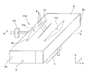
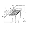
- FIG. 1 is a perspective view showing a first embodiment of an inkjet head of the present invention.
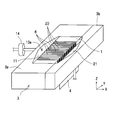
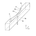
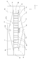
- FIG. 2 is a cross-sectional view taken along the line A-A ′ of FIG. 1. It is a perspective view of the inkjet head which shows the state which removed the nozzle plate. It is a perspective view of a piezoelectric substrate and a flexible cable. It is a top view of the inkjet head which shows the state which removed the nozzle plate. It is an enlarged view which shows the state which the fillet of the adhesive agent generate
- FIG. 1 is a perspective view showing a first embodiment of an ink jet head according to the present invention.
- FIG. 2 is a cross-sectional view taken along the line AA ′ in FIG.
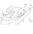
- FIG. 3 shows a state where the nozzle plate of the inkjet head is removed.
- the inkjet head 100 includes a piezoelectric substrate 1, a nozzle plate 2, and a main body 3.
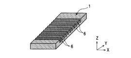
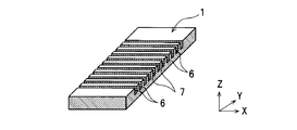
- the piezoelectric substrate 1 has a plurality of individual ink grooves 6 separated from each other by a partition wall 20 and provided with electrodes on the inner wall on the upper surface.
- Each individual ink groove 6 extends in one direction (X-axis direction) and is open at both ends.
- the plurality of individual ink grooves 6 are arranged in parallel with an interval in the other direction (Y-axis direction) orthogonal to the one direction. For the sake of clarity, the number and depth of the individual ink grooves 6 are not accurately illustrated.
- the length of the one direction (X-axis direction) of the piezoelectric substrate 1 is the length of the individual ink groove 6, for example, when the length of the individual ink groove 6 is 5 mm, the piezoelectric substrate The length in one direction (X-axis direction) of 1 may be 5 mm. The length of the piezoelectric substrate 1 in the other direction (Y-axis direction) varies depending on the number, width, and pitch of the individual ink grooves 6.
- two piezoelectric materials whose polarization directions are opposite to each other at the approximate center in the depth direction of the individual ink groove 6 are bonded in advance with an adhesive.
- an adhesive For example, a thin plate of 0.15 mm and a thick plate of 1.85 mm are pasted together.
- the thin plate portion and the thick plate portion of the individual ink groove 6 are deformed in opposite directions, thereby being an area surrounded by the individual ink groove 6 and the nozzle plate 2. Ink is ejected by changing the volume of the pressure generating chamber.
- the main body 3 has a recess, and the piezoelectric substrate 1 is attached to the recess.
- the piezoelectric substrate 1 is bonded and fixed to the main body 3 via an elastic adhesive.
- the elastic adhesive refers to an adhesive having a hardness of 70 or less in Shore D units.
- PM100 manufactured by Cemedine
- 3065E manufactured by ThreeBond
- SIFEL610 Shin-Etsu Chemical Co., Ltd.
- the main body 3 includes a first member 3a and a second member 3b.
- the main body 3 has a first common ink groove 11 and a second common ink groove 21.
- the first common ink groove 11 communicates with the plurality of individual ink grooves 6 on one end side of the plurality of individual ink grooves 6.
- the second common ink groove 21 communicates with the plurality of individual ink grooves 6 on the other end side of the plurality of individual ink grooves 6.
- the nozzle plate 2 is arranged so as to cover the plurality of individual ink grooves 6, the first common ink groove 11, and the second common ink groove 21 from above, and a plurality of individual inks together with the plurality of individual ink grooves 6.
- a chamber 6 a is defined, a first common ink chamber 11 a is defined together with the first common ink groove 11, and a second common ink chamber 21 a is defined together with the second common ink groove 21. That is, the nozzle plate 2 is sized to seal the recess of the main body 3.
- the nozzle plate 2 has nozzle holes 8 at positions corresponding to the individual ink grooves 6.
- the nozzle plate 2 is provided with two bubble discharge ports 18 communicating with the first common ink chamber 11a, as indicated by phantom lines.
- the contact surface side end of the nozzle plate 2 of the main body 3 needs not to protrude beyond the contact surface side end of the nozzle plate 2 in the partition wall 20 of the piezoelectric substrate 1. This is because the end of the main body 3 and the end of the partition wall 20 are bonded to the nozzle plate 2 at the same time. If the end of the main body 3 protrudes, the nozzle plate 2 is lifted by the main body 3, and the nozzle plate 2 cannot be bonded to the end of the partition wall 20, that is, the individual ink chambers. An area 6a in the communication state is generated. If there is an area communicating with the individual ink chamber 6a, ink flows back and forth, and ink cannot be ejected efficiently, resulting in a decrease in speed.
- the main body 3 has a first channel port 13a communicating with the first common ink chamber 11a and a second channel port 13b communicating with the second common ink chamber 21a. Each of the first flow path port 13a and the second flow path port 13b is provided.
- the first flow path port 13a is an inlet for supplying ink to the first common ink chamber 11a
- the second flow path port 13b is a flow of ink for discharging ink from the second common ink chamber 21a. It is an exit.
- the main body 3 includes therein a first flow path portion 5a in which the first flow path port 13a is an open end and a second flow path section 5b in which the second flow path port 13b is an open end.
- the first flow path part 5a and the second flow path part 5b are linear.
- the inner surfaces of the cross sections of the first flow path part 5a and the second flow path part 5b have curved surfaces. That is, the inner surfaces of the cross sections of the first flow path portion 5a and the second flow path portion 5b are formed in a circular shape.
- the cross-sectional areas of the first flow path portion 5a and the second flow path portion 5b are larger than the cross-sectional areas of the individual ink chambers 6a.
- ink is supplied from a supply tank (not shown) to the first common ink chamber 11a via the first flow path portion 5a.
- the ink passes through the individual ink chambers 6a, flows into the second common ink chamber 21a, and flows to the waste liquid tank through the second flow path portion 5b.
- the partition wall 20 is sheared and deformed by the voltage applied to the electrode of the individual ink groove 6, the volume of the individual ink chamber 6 a is deformed, and the ink is ejected from the nozzle hole 8.
- the inkjet head 100 is used, for example, such that the nozzle hole 8 is disposed downward (gravity direction) and ink is ejected downward from the nozzle hole 8. That is, the inkjet head 100 is used with the Z-axis direction facing downward.
- the nozzle hole 8 is located at the center of the individual ink groove 6 in the longitudinal direction (X-axis direction). This is because when the nozzle hole 8 is positioned at the center in the longitudinal direction of the individual ink groove 6, when a voltage is applied to the individual ink groove 6 by an external voltage application mechanism, the pressure wave generated by the individual ink groove 6. The propagation efficiency is the best. As a result, ink can be ejected at a low ejection voltage.
- the nozzle plate 2 does not have the nozzle hole 8 at a position corresponding to the endmost individual ink groove 6 in the other direction (Y-axis direction).
- the individual ink grooves 6 (dummy grooves) without the nozzle holes 8 are not limited to one at both ends. However, if the flow resistance is different from other ink grooves, the ink does not flow on average in each ink groove, so the ink groove without nozzle holes has the same flow resistance as the ink groove with nozzle holes, that is, The same channel cross-sectional area and the same channel length are required.
- the piezoelectric substrate 1 has an electrode lead portion 9 formed on one side surface portion (end surface portion) thereof.
- the electrode lead portion 9 is electrically connected to the electrode 7 provided on the inner surface of the individual ink groove 6.
- a flexible cable 4 is connected to the electrode lead-out portion 9.
- the electrode 7 and the electrode lead-out portion 9 are indicated by oblique lines.
- the flexible cable 4 is located on the joint surface between the first member 3a and the second member 3b. That is, the joint surface of the second member 3b has a recess into which the flexible cable 4 is fitted.
- the voltage is applied to the electrode lead-out portion 9 from the outside via the flexible cable 4.
- the applied voltage is transmitted to the electrode 7 of the individual ink groove 6 that is electrically connected to the electrode lead-out portion 9. Due to the voltage applied to the electrode 7, the wall surface of the individual ink groove 6 of the piezoelectric substrate 1 is sheared and deformed, the volume of the individual ink chamber 6 a is deformed, and the ejected ink is ejected from the nozzle hole 8.
- the bubble discharge port 18 is located on the outer side in the other direction from the outermost individual ink groove 6 (dummy groove 6b) in the other direction (Y direction). All of the bubble outlets 18 are circular. All the hole diameters of the bubble discharge ports 18 are smaller than all the hole diameters of the nozzle holes 8.
- the first common ink chamber 11a and the second common ink chamber 21a have a space to a position outside the outermost individual ink groove 6.
- the reason for this is that, as shown in FIG. 5B, when bonding the main body 3 and the piezoelectric substrate 1 with an adhesive, it is necessary to apply a sufficient adhesive to prevent insufficient sealing. is there. Therefore, there is a problem that a fillet 17 (shown by hatching) due to an adhesive is generated between the main body 3 and the piezoelectric substrate 1.
- the individual ink grooves 6 are filled with the adhesive because the adhesive is successively sucked into the individual ink grooves 6 due to capillary action.
- the ink groove 6 cannot be used as a pressure generation chamber.
- the first plane S1 in the area where the first plane S1 perpendicular to the other direction (Y-axis direction) and the first common ink chamber 11a intersect, the first plane S1 is the center of the first flow path port 13a. Is larger than the area at the position where the first flat surface S1 intersects the extreme individual ink groove 6 (dummy groove 6b) in the other direction. That is, this area decreases stepwise or continuously from the first flow path port 13a to the dummy groove 6b.
- the area at the position where the second plane S2 intersects the center of the second flow path port 13b is The area of the second plane S2 is larger than the area at the position where it intersects with the individual ink groove 6 (dummy groove 6b) at the end in the other direction. That is, this area decreases stepwise or continuously from the second flow path port 13b to the dummy groove 6b.
- At least a part of the side surface 11b of the first common ink groove 11 facing the end of the individual ink groove 6 is formed as a concave curved surface.
- At least a part of the side surface 21b of the second common ink groove 21 facing the end of the individual ink groove 6 is formed as a concave curved surface.
- the first common ink groove 11 has a width L in the one direction on a plane parallel to a plane including the one direction (X-axis direction) and the other direction (Y-axis direction).
- the width at the position where one plane S1 intersects the center of the first flow path port 13a is larger than the width at the position where the first plane S1 intersects the individual ink groove 6 (dummy groove 6b) at the extreme end in the other direction. . That is, the width L is reduced stepwise or continuously from the first flow path port 13a to the dummy groove 6b.
- the second plane S2 is the first plane.
- the width at the position intersecting the center of the two flow path ports 13b is larger than the width at the position where the second plane S2 intersects the extreme individual ink groove 6 (dummy groove 6b) in the other direction. That is, the width L is reduced stepwise or continuously from the second flow path port 13b to the dummy groove 6b.
- the flow path resistance from the flow path port to the opening end of the ink groove has a large difference between the ink groove at the center and the ink groove at the end.
- the position of the meniscus in the nozzle hole changes, and variations in ink grooves occur in the discharge speed and discharge volume.
- the shape of the common ink chamber is preferably a shape that takes into account the flow path resistance of each ink groove.
- the bubble outlet 18 is preferably equal to or smaller than the nozzle hole and further circular.
- negative pressure is always applied to the inside of the ink jet head so that the ink does not fall from the nozzle hole.
- air is sucked in from the nozzle holes, so that an appropriate negative pressure is selected according to the size of the nozzle holes and the type of ink, so that the meniscus in the nozzle holes is kept constant.
- the bubble discharge port 18 since the bubble discharge port 18 has a circular shape, the meniscus is not easily collapsed and stabilized, and air suction from the bubble discharge port 18 due to the meniscus breakage or unintentional ink discharge from the bubble discharge port 18 is prevented.
- the second plane S2 is the second channel port 13b.
- the depth at the position that intersects the center is the same as the depth at the position where the second plane S2 intersects with the individual ink groove 6 (dummy groove 6b) at the extreme end in the other direction.
- the depth at the position where the first plane S1 intersects the center of the first flow path port 13a is the depth described above.
- the first plane S1 has the same depth as that at the position where it intersects with the endmost individual ink groove 6 (dummy groove 6b) in the other direction.
- At least a part of the boundary surface between the side surface 11b of the first common ink groove 11 and the bottom surface 11c of the first common ink groove 11 facing the nozzle plate 2 is a concave curved surface. Is formed. At least a part of the boundary surface between the side surface 21b of the second common ink groove 21 and the bottom surface 21c of the second common ink groove 21 facing the nozzle plate 2 is formed as a concave curved surface.
- the first flow path port 13a is located at the approximate center in the other direction (Y-axis direction) of the first common ink groove 11, and the second flow path port 13b is The second common ink groove 21 is located approximately at the center in the other direction.
- the second flow path port 13 b is located on the bottom surface 21 c of the second common ink groove 21.
- a filter 14 communicates with the first flow path portion 5a.
- the shortest distance between the bottom surface 21 c of the second common ink groove 21 and the nozzle plate 2 is larger than the shortest distance between the bottom surface of the individual ink groove 6 and the nozzle plate 2.
- the shortest distance between the bottom surface 11 c of the first common ink groove 11 and the nozzle plate 2 is equal to or smaller than the shortest distance between the bottom surface of the individual ink groove 6 and the nozzle plate 2.
- the bubbles 15 indicated by oblique lines enter the first common ink chamber 11a through the first flow path port 13a.
- the flow path resistance in the flow path of the individual ink groove 6 is higher than the flow path in the first common ink chamber 11a. Even if it hits, it does not enter the individual ink groove 6.
- the side surface 11b of the first common ink groove 11 is a smooth shape having a curved surface, the bubble 15 pushed into the opening end 16 is not caught by the side surface 11b, and the bubble 15 is trapped. Can be prevented.
- the first flow path port 13a is positioned at a substantially central portion in the Y direction of the first common ink groove 11, the bubbles 15 are distributed to the individual ink grooves 6 at the extreme end without any deviation, and the above-mentioned efficiency is improved. Bubbles 15 can be discharged.
- the width of the first common ink groove 11 in the X-axis direction is continuously reduced from the first flow path port 13a to the dummy groove 6b. That is, the shape of the side surface 11b of the first common ink groove 11 is a shape that is guided so as to be pressed against the opening end 16 as the bubble 15 moves toward the dummy groove 6b. As a result, the bubbles 15 can be guided to a portion of the first common ink chamber 11a outside the most individual ink groove 6b, and the bubbles 15 can be passed through the individual ink grooves 6. it can.
- the second flow path port 13b is larger than the flow path cross-sectional area of the individual ink grooves 6.
- the bubbles 15 trapped in the portion outside the outermost individual ink groove 6 b in the first common ink chamber 11 a continue to be trapped without passing through the individual ink groove 6.
- the ink jet head in this state is pressurized on the first common ink chamber 11a side or forcibly sucked from the ink ejection direction side, and the pressure difference between the first common ink chamber 11a and the atmospheric pressure. As a result, the ink can be discharged from the nozzle hole 8 and the bubble 15 can be discharged from the bubble discharge port 18.
- a groove forming step is performed. That is, a plurality of individual ink grooves 6 are formed by scanning the dicing blade on the piezoelectric substrate 1 that is an actuator member a plurality of times in a fixed direction (X-axis direction).
- the piezoelectric substrate 1 having a size of 5 mm ⁇ 50 mm and a thickness of 2 mm was used.
- the depth of the individual ink grooves 6 was about 300 ⁇ m, the width was 100 ⁇ m, the pitch of the individual ink grooves 6 was about 200 ⁇ m, and the number of individual ink grooves 6 was 200.
- the width of the individual ink groove 6 can be changed by the thickness of the dicing blade to be used, and the depth of the individual ink groove 6 can be changed by changing the cutting amount of the dicing blade.
- a conductive film forming step is performed. That is, a conductive film to be an electrode is formed on the inner wall of the individual ink groove 6 of the piezoelectric substrate 1, and a conductive film to be an electrode lead portion is formed on the side surface of the piezoelectric substrate 1.
- the film thickness on the inner wall of the copper individual ink groove 6 was formed to be 0.5 ⁇ m at the thinnest portion.
- the hatched portion is a portion where a conductive film is formed.
- the conductive film is formed on the entire surface except the surface on the back side of the surface on which the individual ink grooves 6 of the piezoelectric substrate 1 are formed. It is formed. At this time, the thickness of the copper film formed on the side surface of the piezoelectric substrate 1 where the individual ink grooves 6 are opened was 1 ⁇ m. The film thickness of copper formed on the inner wall of the individual ink groove 6 is different from the film thickness of copper formed on the side surface of the piezoelectric substrate 1 where the individual ink groove 6 is opened. This is due to differences in surroundings.
- a removal process is performed. That is, the unnecessary conductive film on the surface where the individual ink grooves 6 of the piezoelectric substrate 1 are formed is removed.
- This removal step can be performed, for example, by scanning the upper surface of the piezoelectric substrate 1 a plurality of times with a dicing blade. At this time, it is preferable that the surface of the piezoelectric substrate 1 is slightly ground with a dicing blade so that the individual ink grooves 6 adjacent to each other on the surface of the piezoelectric substrate 1 where the individual ink grooves 6 are formed are reliably insulated.
- an electrode 7 is formed on the inner wall of the individual ink groove 6, and a conductive film is formed on the side surface of the piezoelectric substrate 1.
- a separation step is performed. That is, the separation groove 12 is formed by scanning the conductive film formed on the side surface of the piezoelectric substrate 1 with a dicing blade a plurality of times in a fixed direction (Z-axis direction). By this separation step, electrode lead portions 9 corresponding to the individual ink grooves 6 are formed.
- the electrode 7 formed on the inner wall of the individual ink groove 6 and the electrode lead-out portion 9 are electrically connected on the side surface of the piezoelectric substrate 1 where the individual ink groove 6 opens.
- the separation process is performed on the side surface of the piezoelectric substrate 1 where the individual ink grooves 6 are opened, with the depth of the separation grooves 12 being 10 ⁇ m and the width being 50 ⁇ m. Further, the portion where the separation groove 12 is formed is between the individual ink grooves 6 and is located at a position where no electrical conduction is established between the adjacent individual ink grooves 6. Such a separation process was performed on both sides of the side surface of the piezoelectric substrate 1 where the individual ink grooves 6 are open.
- the piezoelectric substrate 1 becomes symmetrical, so that the direction is not mistaken in the subsequent process. Further, when the electrode lead portion 9 on one side is damaged, the yield can be improved because the electrode lead portion 9 on the opposite side can be used.
- a conductive member is connected to the electrode lead portion 9 of the piezoelectric substrate 1 processed in this way.
- the flexible cable 4 is used as the conductive member, and the connection with the electrode lead-out portion 9 is an ACF connection.
- the other end of the flexible cable 4 is connected to an external voltage application mechanism directly or via another member in order to eject ink.
- the reason why the flexible cable is used as the conductive member is that the flexible cable is easy to be deformed and can be easily used in the process in the subsequent process and can suppress a decrease in yield. There is no.
- the piezoelectric substrate 1 is bonded to the first member 3a of the main body 3.
- An elastic adhesive was applied to the bonding surface between the first member 3 a and the piezoelectric substrate 1 and pressed against the piezoelectric substrate 1.
- the connecting portion between the flexible cable 4 and the electrode lead-out portion 9 is a common ink chamber. It becomes the composition which becomes the outside.
- the nozzle plate 2 is adhered so as to cover the individual ink grooves 6 to complete the ink jet head.
- the main body 3 has the first common ink groove 11 communicating with the plurality of individual ink grooves 6 on one end side of the plurality of individual ink grooves 6 and the plurality of individual inks.
- a second common ink groove 21 communicating with the plurality of individual ink grooves 6 is provided on the other end side of the groove 6. Therefore, by appropriately adjusting the width and depth of the first common ink groove 11 and the second common ink groove 21, the flow resistance of the first common ink groove 11 and the second common ink groove 21 is reduced. Compared to the flow path resistance of the individual ink chamber 6a, it can be made sufficiently small, and the ink flow through the individual ink chamber 6a in the ink jet head can be easily promoted. In addition, the number of ink jet heads that can be obtained from one wafer-like piezoelectric substrate 1 (so-called “number of picks”) is not affected at all.
- the main body 3 communicates with the first common ink chamber 11a to supply ink to the first common ink chamber 11a, and communicates with the second common ink chamber 21a. And a second channel port 13b for discharging ink from the second common ink chamber 21a. Therefore, when the ink flows from the first flow path port 13a to the second flow path port 13b, the ink does not have a flow path that passes through other than the individual ink grooves 6 so that the ink flows through the individual ink grooves 6. As a result, the stagnation of ink in the individual ink groove 6 can be prevented.
- the bubble discharge port 18 communicating with the first common ink chamber 11a is provided so as to be located outside the outermost individual ink groove 6 in the other direction, the first The bubbles 15 that try to stay outside the outermost individual ink groove 6 in the common ink chamber 11a can be discharged from the bubble discharge port 18, and the trapping of the bubbles 15 can be reliably prevented.
- the discharge parameter becomes unstable or causes non-discharge due to the unintended bubble 15 flowing.
- all of the bubble discharge ports 18 are formed in the nozzle plate 2. For this reason, the differential pressure generated during maintenance of nozzle clogging is automatically applied to the bubble discharge port 18, so that a simple maintenance member or the like is not required, so that the first common ink chamber 11 a can be easily removed. It is possible to reliably discharge the bubbles 15. As a result, it is possible to provide an inkjet head that does not cause trapping of the bubbles 15 or ink stagnation in a simple and reliable manner. It should be noted that at least one of the bubble discharge ports 18 may be formed in the nozzle plate 2.
- the bubble discharge ports 18 have a circular shape, the meniscus is not easily collapsed and is stable, and an air suction phenomenon from the bubble discharge port 18 due to the meniscus breakage or an unintended ink from the bubble discharge port 18. Emission can be prevented. Note that at least one of the bubble discharge ports 18 may be circular.
- ink when ink is not ejected from the ink jet head, it is well known to apply a negative pressure to the inside of the ink jet head so that the ink does not sag from the nozzle holes 8. If too much negative pressure is applied, air will be sucked from the nozzle hole 8, so that a suitable negative pressure is selected according to the size of the nozzle hole 8 and the type of ink, so that the meniscus in the nozzle hole 8 is kept constant. It is.
- all the hole diameters of the bubble discharge port 18 are smaller than all the hole diameters of the nozzle hole 8. Therefore, compared with the nozzle hole 8, the meniscus can be maintained more firmly, and the meniscus can be stabilized while having a sufficient margin against the negative pressure applied to the inside of the inkjet head, which is not intended. Ink discharge can be reliably prevented. In addition, it is sufficient that at least one hole diameter of the bubble discharge port 18 is smaller than at least one hole diameter of the nozzle hole 8.
- the area where the first plane S1 and the first common ink chamber 11a intersect is the first plane S1 is the other. It is larger than the area at the position where it intersects the individual ink groove 6 at the extreme end in the direction.
- the bubbles 15 mixed into the first common ink chamber 11a from the first flow path port 13a do not first pass through the individual ink grooves 6 having a high flow resistance, but hit the end of the piezoelectric substrate 1.
- the bubble 15 moves to the position of the individual ink groove 6 on the end portion side, it moves toward the end portion in the other direction far from the first flow path port 13a.
- the area at the position where the second plane S2 intersects the center of the second flow path port 13b is larger than the area at the position where the second plane S2 intersects the individual ink groove 6 at the extreme end in the other direction. Therefore, the bubbles 15 flowing into the second common ink chamber 21a through the first common ink chamber 11a and the individual ink grooves 6 are guided in the direction of the second flow path port 13b having a large cross-sectional area. It will move. As a result, the bubbles 15 can be effectively discharged in the second common ink chamber 21a, and the bubbles 15 can be prevented from remaining.
- the side surface 11b of the first common ink groove 11 is formed in a concave curved surface.
- the side surface 21b of the second common ink groove 21 is formed in a concave curved surface. For this reason, when the bubble 15 is guided by the side surface 21b of the second common ink groove 21 so as to be pressed against the piezoelectric substrate 1 as it moves to the position of the individual ink groove 6 on the end side, it is flat or square when guided. It is possible to prevent the bubbles 15 from remaining on the side surface 21b of the second common ink groove 21 without being trapped.
- first plane S1 intersects the center of the first flow path port 13a in the width L in the one direction of the first common ink groove 11 on a plane parallel to the plane including the one direction and the other direction.
- the width at the position is larger than the width at the position where the first plane S1 intersects the individual ink groove 6 at the extreme end in the other direction.
- the side surface 11b of the first common ink groove 11 facing the end of the individual ink groove 6 can be formed narrower toward the end of the individual ink groove 6 than the first flow path port 13a.
- the side surface 11b of the first common ink groove 11 can guide the bubble 15 to the bubble discharge port 18 while pressing the bubble 15 against the piezoelectric substrate as it moves to the position of the individual ink groove 6 on the end side. It is possible to reliably prevent the bubbles 15 from remaining in the common ink chamber 11a.
- the second plane S2 intersects the center of the second flow path port 13b in the width L in the one direction of the second common ink groove 21 on a plane parallel to the plane including the one direction and the other direction.
- the width at the position is larger than the width at the position where the second plane S2 intersects the individual ink groove 6 at the extreme end in the other direction.
- the bubbles 15 can be guided in the direction of the second flow path port 13b by the side surface 21b of the second common ink groove 21, and the bubbles 15 can be reliably discharged in the second common ink chamber 21a.
- the flow path portion 5a and the second flow path portion 5b is linear, it is possible to prevent the bubbles 15 from being trapped.
- the flow path portion is formed in a polygonal line shape or a stepped shape, the bubbles 15 are trapped in the place, and the unintended bubbles 15 flow to cause unstable discharge.
- the inner surface of the cross section in at least one of the first flow path part 5a and the second flow path part 5b has a curved surface, it is possible to prevent the bubbles 15 from being trapped.
- the flow path portion is formed in a flat surface or a square shape, the bubbles 15 are trapped in the place, and the unintended bubbles 15 flow to cause unstable discharge.
- the inner surface of the cross section of at least one of the first flow path portion 5a and the second flow path portion 5b is formed in a circular shape, the flow path portion can be easily processed, and the trap of the bubbles 15 can be obtained. Can be reliably prevented.
- the cross-sectional areas of the first flow path portion 5a and the second flow path portion 5b are larger than the cross-sectional areas of the individual ink chambers 6a. Therefore, the bubbles 15 that have flowed into the common ink chambers through the individual ink chambers 6a have the same size and are smoothly discharged through the flow passage openings.
- the nozzle plate 2 does not have the nozzle hole 8 at a position corresponding to the outermost individual ink groove 6. For this reason, many bubbles 15 pass through the outermost individual ink groove 6, but the outermost individual ink groove 6 that becomes unstable when the bubble 15 passes is used for ink discharge. The reliability can be improved. Further, only the outermost individual ink groove 6 such as an excess adhesive when the nozzle plate 2 is adhered to the piezoelectric substrate 1 or an excess adhesive when the main body 3 is adhered to the piezoelectric substrate 1 is adhered. There is a possibility that the amount of the agent increases, and the above-mentioned endmost individual ink groove 6 cannot be used as an ink discharge flow path. However, the above-described endmost individual ink groove 6 that becomes unstable ejection is not used for ink ejection, and the reliability can be improved.
- the main body 3 is composed of a plurality of members, the cost for producing the members can be reduced. Moreover, it can be prevented by sealing the adhesive in a state where the adhesive sealing is insufficient due to the complicated shape, and leakage of the ink flow path can be reliably prevented.
- the piezoelectric substrate 1 is bonded and fixed to the main body 3 via an elastic adhesive, even if the piezoelectric substrate 1 and the main body 3 are made of different materials, the elastic adhesive The difference in thermal expansion between the piezoelectric substrate 1 and the main body 3 can be absorbed to prevent the reliability of temperature change from being lowered.
- the elastic adhesive is not used, if the main body 3 is formed using metal or resin in consideration of cost, the main body 3 is thermally expanded with the piezoelectric substrate 1 which is ceramic. The difference in coefficient increases, causing member destruction and leakage.
- first flow path port 13 a is positioned at the approximate center of the first common ink groove 11 in the other direction
- the second flow path port 13 b is approximately the other direction of the second common ink groove 21. Located in the center. Therefore, the air bubbles 15 mixed into the common ink chamber through the supply-side channel port of the first channel port 13a and the second channel port 13b are not biased, and the individual ink grooves at both extreme ends in the other direction are not biased. 6 can be passed, and the bubbles 15 can be efficiently discharged.
- the shortest distance between the bottom surface 21c of the second common ink groove 21 facing the nozzle plate 2 and the nozzle plate 2 is the bottom surface of the individual ink groove 6 facing the nozzle plate 2 and the nozzle plate. It is larger than the shortest distance between the two. Therefore, when the nozzle hole 8 is disposed downward (gravity direction) and ink is ejected downward, the bubbles 15 receive buoyancy and the bottom surface of the individual ink groove 6 and the bottom surface 21c of the second common ink groove 21 are received. Move along.
- the bottom surface 21c of the second common ink groove 21 is located on the buoyancy direction side with respect to the bottom surface of the individual ink groove 6, the bubbles 15 that have passed through the individual ink chamber 6a become the second common ink. After being discharged into the chamber 21a, backflow can be prevented.
- the shortest distance between the bottom surface 11c of the first common ink groove 11 facing the nozzle plate 2 and the nozzle plate 2 is the bottom surface of the individual ink groove 6 facing the nozzle plate 2 and the nozzle plate. It is equal to or smaller than the shortest distance between the two. Therefore, when the nozzle hole 8 is disposed downward (gravity direction) and ink is ejected downward, the bubbles 15 receive buoyancy and the bottom surface 11c of the first common ink groove 11 and the bottom surface of the individual ink groove 6 are detected. Move along.
- the air bubbles 15 are not retained in the first common ink chamber 11a. Therefore, the ink can be discharged to the individual ink chamber 6a.
- the nozzle hole 8 is disposed downward (gravity direction) so that the ink is directed downward. In the case of discharging to the bubble 15, the bubble 15 receives buoyancy and contacts the bottom surface 21 c of the second common ink groove 21.
- the buoyancy direction received by the mixed bubbles 15 is the same as the direction of the outlet, the bubbles 15 can be efficiently discharged from the second common ink chamber 21a.
- the filter 14 since the filter 14 is communicated with the first flow path portion 5a, the filter 14 is disposed on the inlet side to prevent the bubbles 15 from remaining by preventing dust from being mixed into the inkjet head. In addition to preventing, it is possible to prevent a decrease in reliability of non-ejection occurrence due to dust.
- the conductive film forming step is performed by a sputtering method, it has been confirmed that a similar conductive film can be formed by an ion plating method or an electroless plating method.
- the ion plating method can form a conductive film with good adhesion
- the electroless plating method forms a conductive film with a small film thickness variation even on the piezoelectric substrate 1 on which a plurality of complicated groove shapes are formed. can do.
- the vapor phase growth method and the vapor deposition method are not suitable because the substrate surface temperature of the piezoelectric substrate 1 tends to increase.
- the removal step is performed after the conductive film formation step.
- a portion where the conductive film is not desired to be formed is covered with a resist material in advance to form the conductive film.
- the resist material may be peeled off after the process.
- the separation groove 12 is formed by the dicing blade, but machining other than the dicing blade such as a wire saw may be performed. Furthermore, not the separation by the dicing blade, the ejection performance similar to the ink jet head separated by the dicing blade is also applied to the ink jet head in which the unnecessary portion of the conductive film is removed by YAG laser irradiation and the electrode lead portion 9 is formed. It was confirmed that it has circulation performance. Regarding the type of laser, it was not necessary to be a YAG laser, and it was confirmed that, for example, the electrode lead-out portion 9 can be formed by separating the conductive film on the side surface of the piezoelectric substrate 1 using a CO2 laser or an excimer laser. .
- connection method between the electrode lead-out portion 9 and the conductive member is ACF connection in this embodiment.
- the connection method is not limited to this, and it was confirmed that the connection can be achieved using a conductive paste such as silver paste or solder.
- a conductive paste such as silver paste or solder.
- the conductive paste or solder applied to the electrode lead-out portion 9 may flow into the groove 6. Therefore, the length obtained by subtracting the depth of the groove 6 from the thickness of the piezoelectric substrate 1. That is, it is preferable to use a conductive paste or solder only when the length capable of connecting a conductive member such as the flexible cable 4 to the electrode lead portion 9 is at least 1.5 mm.
- steps described in the present embodiment are the minimum necessary steps, and steps other than those described above may be added as necessary.
- a step of machining a groove as a mark for making a processing reference somewhere on the piezoelectric substrate 1 or a step of covering the electrode 7 with a protective film when the electrode 7 corrodes due to contact with ink is added. May be.
- the piezoelectric substrate 1 and the main body 3 may be formed of the same material, and a decrease in reliability of temperature change due to a difference in linear expansion coefficient between the piezoelectric substrate 1 and the main body 3 can be prevented.
- FIG. 9 shows a second embodiment of the inkjet head of the present invention. The difference from the first embodiment will be described. In the second embodiment, the shapes of the first common ink groove and the second common ink groove are different. Since other structures are the same as those of the first embodiment, description thereof is omitted.
- At least a part of the bottom surface 11c of the first common ink groove 11 is formed in a concave curved surface.
- At least a part of the bottom surface 21c of the second common ink groove 21 is formed in a concave curved surface.
- the depth at the position where the first plane S1 intersects the center of the first flow path port 13a is larger than the depth at the position where the first plane S1 intersects the individual ink groove 6 (dummy groove 6b) at the extreme end in the other direction (Y-axis direction). That is, this depth decreases stepwise or continuously from the first flow path port 13a to the dummy groove 6b.
- the depth at the position where the second plane S2 intersects the center of the second flow path port 13b is the above-described depth.
- the second plane S2 is larger than the depth at the position where it intersects the extreme individual ink groove 6 (dummy groove 6b) in the other direction. That is, this depth decreases stepwise or continuously from the second flow path port 13b to the dummy groove 6b.
- the nozzle hole 8 is disposed downward (in the direction of gravity) so that the ink is directed downward.
- the bubbles 15 are subjected to buoyancy and are pressed against the bottom surface 11c of the first common ink groove 11 on the opposite side in the direction of gravity, the bubbles 15 are not trapped by a flat surface or a step. Remaining at the bottom surface 11c of the first common ink groove 11 can be prevented.
- the bottom surface 21c of the second common ink groove 21 is formed in a concave curved surface. Therefore, when the nozzle hole 8 is arranged downward (gravity direction) and ink is ejected downward, the bubbles 15 are pressed against the bottom surface 21c of the second common ink groove 21 on the opposite side of the gravity direction due to buoyancy. Sometimes, it is possible to prevent the bubbles 15 from remaining on the bottom surface 21c of the second common ink groove 21 without being trapped by a plane or a step.
- the depth at the position where the first plane S1 intersects the center of the first flow path port 13a is the first plane S1. Is greater than the depth at the position where it intersects the individual ink groove 6 at the extreme end in the other direction. For this reason, the bottom surface 11c of the first common ink groove 11 facing the nozzle plate 2 can be formed shallower toward the end of the individual ink groove 6 than the first flow path port 13a.
- the nozzle hole 8 is disposed downward (gravity direction) and ink is ejected downward, the bubble 15 is moved to the ink groove position on the end side by the bottom surface 11c of the first common ink groove 11.
- the air bubbles 15 can be surely discharged from the air bubble outlet 18 by bringing the air bubbles 15 into contact with the air bubble outlet 18.
- the depth at the position where the second plane S2 intersects the center of the second flow path port 13b is the second plane S2. Is greater than the depth at the position where it intersects the individual ink groove 6 at the extreme end in the other direction. Therefore, the bottom surface 21c of the second common ink groove 21 facing the nozzle plate 2 can be formed shallower toward the individual ink groove 6 side, which is the endmost than the second flow path port 13b.
- the bubble 15 can be guided toward the second flow path port 13b by the bottom surface 21c of the second common ink groove 21.
- the bubbles 15 can be reliably discharged in the second common ink chamber 21a.
- FIG. 10 shows a third embodiment of the ink jet head of the present invention. The difference from the first embodiment will be described. In the third embodiment, the shapes of the first common ink groove and the second common ink groove are different. Since other structures are the same as those of the first embodiment, description thereof is omitted.
- At least a part of the side surface 11b and the bottom surface 11c of the first common ink groove 11 is formed in a concave curved surface.
- At least a part of the side surface 21b and the bottom surface 21c of the second common ink groove 21 is formed as a concave curved surface.
- the shapes of the first common ink groove and the second common ink groove of the inkjet head 400 are the same as the shapes of the first common ink groove and the second common ink groove of the inkjet head 100 of the first embodiment.
- This is a shape obtained by adding the shapes of the first common ink groove and the second common ink groove of the inkjet head 300 of the second embodiment.
- the third embodiment has the effects of the first embodiment and the effects of the second embodiment.
- FIG. 11 shows a fourth embodiment of the inkjet head of the present invention. The difference from the first embodiment will be described. In the fourth embodiment, the position of the bubble discharge port is different. Since other structures are the same as those of the first embodiment, description thereof is omitted.
- the bubble discharge port 18 is formed on the inner surface of the first common ink groove 11 of the main body 3. All of the bubble discharge ports 18 are formed on the bottom surface of the main body 3 facing the nozzle plate 2 in the first common ink groove 11.
- the bubble discharge port 18 is formed on the inner surface of the first common ink groove 11 of the main body 3.
- the nozzle plate 2 is affected by ink adhesion to the nozzle plate 2 and damage to the bubble discharge port 18 during maintenance of the nozzle plate 2 as if the nozzle plate 2 had the bubble discharge port 18. Accordingly, it is possible to stably discharge the bubbles 15 trapped from the bubble discharge port 18 and discharge the staying ink.
- all of the bubble discharge ports 18 are formed on the bottom surface of the main body 3 facing the nozzle plate 2 in the first common ink groove 11. For this reason, when the nozzle holes of the nozzle plate 2 are arranged in the direction of gravity and the bubbles 15 mixed in the first common ink chamber 11a are discharged, the bubble discharge port 18 is in the direction in which the bubbles 15 are subjected to buoyancy. Thus, the bubbles 15 can be discharged efficiently and smoothly. Note that at least one of the bubble discharge ports 18 may be formed on the bottom surface of the main body 3 that faces the nozzle plate 2 in the first common ink groove 11.
- FIG. 12 shows an embodiment of the inkjet head device of the present invention.
- This inkjet head device is, for example, a printer.
- the ink jet head device 700 includes the ink jet head 600 according to any one of the first to fifth embodiments.
- the inkjet head device 700 includes a box body 703, a sheet guide 704 attached to the box body 703, and a holding shaft 705 attached to the box body 703.
- the inkjet head 600 is attached to the holding shaft 705 so as to be able to travel in the direction of the arrow.
- a conveyance roller (not shown), an ink supply / discharge unit, and a control unit are attached.
- the control unit receives image data transmitted from an image processing apparatus such as a computer (not shown), and controls the members to perform printing.
- the inkjet head device 700 receives and processes image data transmitted from an external information processing device (such as a computer or a digital camera), and prints and outputs the image on a printing sheet made of paper, plastic, or the like. .
- an external information processing device such as a computer or a digital camera
- the inkjet head device having the above-described configuration, since the inkjet head 600 is provided, the ejection reliability can be improved.
- the piezoelectric substrate and the main body portion may be formed of a single member that is integrally connected, thereby reducing the cost of labor of combining a plurality of members and due to the difference in linear expansion coefficient between the plurality of members. A decrease in reliability of temperature change can be prevented.
- the main body portion may be an integral type, or may be formed of three or more members. Further, the number, size, and shape of the bubble outlets can be changed depending on the amount and size of the bubbles to be mixed.
Landscapes
- Particle Formation And Scattering Control In Inkjet Printers (AREA)
Abstract
本体部3は、複数の個別インク溝6と連通する第1共通インク溝11および第2共通インク溝21を有する。本体部3は、第1共通インク室11aに連通するインク供給用の第1流路口13aと、第2共通インク室21aに連通するインク排出用の第2流路口13bとを有する。第1共通インク室11aに連通する気泡排出口18が、Y方向の最端の個別インク溝6bよりもY方向の外側に位置するように、設けられている。
Description
この発明は、(プリンター等に用いられる)インクジェットヘッドおよびインクジェットヘッド装置に関する。
近年、プリンターにおいては、インパクト印字装置に代わって、カラー化、多階調化に対応しやすいインクジェット方式などのノンインパクト印字装置が急速に普及している。これに用いるインク噴射装置としてのインクジェットヘッドとしては、特に、印字に必要なインク滴のみを噴射するというドロップ・オン・デマンド型が、噴射効率の良さ、低コスト化の容易さなどから注目されている。ドロップ・オン・デマンド型としては、カイザー(Kyser)方式やサーマルジェット方式が主流となっている。
しかし、カイザー方式は、小型化が困難で高密度化に不向きであるという欠点を有していた。また、サーマルジェット方式は、高密度化には適しているものの、ヒータでインクを加熱してインク内にバブル(泡)を生じさせて、そのバブルのエネルギーを利用して噴射させる方式であるため、インクの耐熱性が要求され、また、ヒータの長寿命化も困難であり、エネルギー効率が悪いため、消費電力も大きくなるという問題を有していた。
このような各方式の欠点を解決するものとして、圧電材料のシェアモード変形を利用したインクジェット方式が提案されている。この方式は、圧電材料からなるインクチャンネルの壁(以下、「チャンネル壁」という。)の両側面に形成した電極を用いて、圧電材料の分極方向と直交する方向に電界を生じさせることで、シェアモードでチャンネル壁を変形させ、その際に生じる圧力波変動を利用してインク滴を吐出するものであり、ノズルの高密度化、低消費電力化、高駆動周波数化に適している。
最近はこのシェアモード変形を利用したインクジェットヘッドを産業用途に利用することが盛んに行われるようになり始めている。たとえば、インクとして導電材料を吐出させることによって配線を描画したり、R,G,Bの各色のインクを吐出させることによってカラーフィルタを作製したり、熱硬化性または紫外線(UV)硬化性のインクを吐出させることによって、マイクロレンズやスペーサなどのような3次元構造物を作製したり、といった応用が進められている。
産業用途においては特に、ノズルの高密度化により高精細に吐出させるという要求の他に、液晶画面の大画面化に伴い、ノズルの低密度化への要求も現れ始めている。産業用途のインクジェットヘッドの利用と民生品のプリンターとしてのインクジェットヘッドの利用とを比較したとき、異なる点としては要求精度の厳しさを挙げることができる。産業用途の方が民生よりもはるかに厳しい精度での動作を要求される。産業用途では、指定されたアドレスに規定量の液滴を着弾させることが要求され、着弾精度、液滴量のコントロールを厳しく要求される。したがって、1つのインクジェットヘッドの中において、本来吐出可能であるべきインクチャンネルが気泡、ダストの混入等の何らかの障害によって吐出不可能となってしまうことは、それが民生用途では問題にならないレベルの発生率であっても、産業用途としてインクジェットヘッドを利用する際には重大な問題となる。
また、このように多岐にわたるインクジェット応用分野の発展に伴い、使用されるインクも多種多様になっている。たとえば、有機溶剤を含有して揮発性の高いインクや、強酸性・強アルカリ性のインク、顔料や樹脂成分を含むインク、ビーズなどの微粒子を含有するインク、さらにはこれらを複合したインクなどが挙げられる。中でもビーズなどの微粒子を含有するインクは、インクの溶媒と含有される微粒子の比重差により、微粒子が沈殿または浮遊し、インク中の微粒子濃度に分布の偏在が引き起こされるおそれがある。分布が偏った場合、吐出時の液滴中に含まれる微粒子数にばらつきが生じてしまい、製品の性能劣化、不良発生をもたらす。このような事態を回避するためには、インクタンク内、インクジェットヘッド内でインクを循環、撹拌させることによって微粒子の沈殿を防止する必要がある。さらに厳密には、吐出時の液滴中に含まれる微粒子数を安定させて吐出させるためには、上述のインクの循環、撹拌はインクがノズル孔の直近にある時点においてもなされることが重要である。また、循環、攪拌をしながらも、吐出するインク体積を一定にするためには各ノズル孔にかかる負圧状態を一定に保つ必要がある。
ノズル孔直近までインクを循環、撹拌させるための技術として、国際公開WO95/31335(特許文献1)に記載されたものがある。特許文献1の第2図、第3図に示されたインクジェットヘッドでは、圧力発生室は、前側にノズル孔を有するノズル板、後ろ側に振動板を配置された空間である。この圧力発生室を挟むように圧力発生室の両側に2つの共通インク室が配置されており、これら2つの共通インク室は圧力発生室に連通している。この装置では、一方の共通インク室から他方の共通インク室へ圧力発生室を介してインクを供給できる構造となっている。このインクジェットヘッドにおいては、ノズル孔のある圧力発生室自体がインクの通り道となるため、ノズル孔の直近までインクを循環することが可能である。また、特許文献1の第4図では、上記インクジェットヘッドを備える記録装置の全体が示されており、この記録装置では、インクカートリッジからインクジェットヘッドを経由してサブタンクへとインクを補充する一方、サブタンクからインクジェットヘッドを経由してインクカートリッジへと水頭差を利用してインクを戻すことも可能となっている。特許文献1の記録装置では、このようにしてインクを循環させている。
また、特開2006-142509号公報(特許文献2)に記載されたインクジェットヘッドでは、圧電基板の表面に互いに平行な2本の溝として2つの共通インク室が設けられている。これら2つの共通インク室の間に挟まれ、なおかつこれら2つの共通インク室の両方に連通するように、多数の溝状の圧力発生室が設けられている。特許文献2に提案されているのは、この溝状圧力発生室の壁部分の圧電材料のシェアモード変形を利用したインクジェットヘッドである。
また、特開2004-1368号公報(特許文献3)には、インクの供給/排出のための共通溝を基板裏面から加工した構造のインクジェットヘッドが記載されている。
インクジェットヘッドのひとつの方式として積層型というものがある。これは各部材を位置合わせしながら重ね合わせることによってインクジェットヘッドの構造を組み立てるものであり、その一例は、特開平6-183029号公報(特許文献4)に記載されている。
また、ノズル孔直近までインクを循環、撹拌させ、なおかつ気泡を排除するための方式が、特許第3161095号公報(特許文献5)に記載されている。
上述したように特許文献1に記載の記録装置では、インクカートリッジとサブタンクとの間でインクがやりとりされる際に、その流通の途上でインクは一方の共通インク室から他方の共通インク室へと圧力発生室を介して供給されるため、ノズル孔直近までインクを循環することが可能であるが、このインクジェットヘッドは積層型のインクジェットヘッドであるという欠点がある。
積層型のインクジェットヘッドは、特許文献4に記載されているように、基台に振動子を取り付けたものである振動子ユニットと、流路構成部材と、振動板形成部材と、圧力発生室となるべき間隙を形成するためのスペーサと、ノズル孔を有するノズル板との5つの部材から構成されている。これらの部材をそれぞれ位置合わせし、重ね合わせることによって組み立てられている。インクジェットヘッドにおいて高い着弾精度と均一な吐出性能を実現するためには、ノズル孔と駆動部の相対位置精度がきわめて重要であり、ノズル孔の中心と駆動部におけるインクの通り道の中心とが合って配置されている必要がある。したがって、これら5つの部材はそれぞれについて高精度な位置合わせが要求される。つまり1つのインクジェットヘッドを作製するためにはこのような高精度な位置合わせを4回繰り返す必要があり、歩留まりの低下を招く。また、特許文献4のインクジェットヘッドは、変位量を確保するため積層型の圧電素子を用いており、かつ、インクジェットヘッドを構成する部品点数自体が多い。このような場合、小型化に適していないとともにコストの増大につながる。
これに対し、非積層型のインクジェットヘッドの例として、特許文献2に記載のシェアモード型のインクジェットヘッドが挙げられる。このインクジェットヘッドは、複数の溝を形成した圧電基板を、長円形の凹部を有するマニホールドに収め、複数個のノズル孔を有するノズルプレートを被せることによって組み立てられている。
この特許文献2のインクジェットヘッドで用いられている圧電基板には次のような溝が形成されている。まず、第1の溝として、ノズルプレートを被せることによって圧力発生室となる複数の平行な溝Aがある。この圧力発生室となる溝Aの内壁には電極が形成されており、外部から電圧が印加されることによりこの圧力発生室となる溝がシェアモード変形しノズルからインクを吐出する。
次に、第2の溝として、前述した各圧力発生室となる溝Aに電気的に接続している溝Bがある。この溝Bの内壁にも電極が形成されており、溝Bと外部の電圧印加機構を電気的に接続することにより、溝Bを介して圧力発生室となる溝Aと電圧を印加することができる。外部の電圧印加機構と電気的に接続するために、またインク漏れを抑制するために、溝Bの深さは圧力発生室となる溝Aに対して非常に浅い必要がある。このため溝Bは溝AとR形状部を介してつながっている。本来、このR形状部は必要のない部分であるが、ダイシングマシン等で溝深さの異なる溝同士を接続するように加工する際に、ブレードのRが転写されることで発生してしまう。ブレードの半径は、各溝に対して非常に大きいため、このR形状部が圧電基板に占める領域は非常に大きく、このR形状部の存在が圧電基板の大型化を招く。
さらに、第3の溝として、圧力発生室となる溝Aと直交するように形成された溝Cがあり、溝Cとノズルプレートにより囲まれた部分が共通インク室となる。共通インク室は、各圧力発生室にインクを供給する働きがあるため、共通インク室は複数の圧力発生室と交わるようにする必要がある。また、共通インク室は十分な量のインクを供給する必要があるため、その容積は十分大きいほうがよい。共通インク室の容積を大きくするためには、溝Cの幅を広げるか、深さを深くする手段があるが、深さを圧力発生室となる溝Aよりも深くすると溝Aと溝Bとを電気的に分断してしまうため、溝Aよりも深くすることができない。そこで幅を広げる必要があるが、溝Cの幅を広げることにより圧電基板は大型化してしまう。
これらの結果により特許文献2の構成ではインクジェットヘッドに必要な圧電基板は大型化し、圧電基板は高価なため材料費の増大が発生してしまう。
また、これに対し、特許文献3に記載のインクジェットヘッドは、インクの供給/排出用の共通溝(共通インク室)を基板裏面から加工した構造であるので、特許文献2に記載のインクジェットヘッドに比べて共通インク室の深さを深くすることができる。これは共通インク室の流路抵抗を下げることにつながるので、インクジェットヘッド内のインクの循環をより円滑にすることができるという利点がある。
しかし、特許文献3に記載のインクジェットヘッドは基板に形成された溝の側壁の一部のみを圧電セラミクスで形成している構成となっているため、吐出性能および信頼性に問題がある。
この構成においては、圧力発生室の側壁のうちインク吐出に寄与する領域は圧電セラミクスで形成されているが、それ以外の領域では側壁は絶縁性のセラミクスなどで構成されている。したがって、側壁の一部である圧電セラミクスが、インクを吐出させるために変形する場合、側壁の圧電セラミクスの両端は絶縁性のセラミクスなどに接着されているので、変形を阻害され、その結果、インクの吐出効率が低下する。また、絶縁性のセラミクスなどに圧電セラミクスを接着している場合、接着剤の厚みばらつきによっても圧電セラミクスの変形ばらつきに影響を及ぼす。したがって、チャンネルごとに吐出特性がばらつくことが予想される。さらに、溝を加工する場合、接着剤部と圧電セラミクスと絶縁性のセラミクスとでは加工特性が異なることにより、段差が生じる場合がある。この段差により電極形成時に導通が得られない場合があり、信頼性に問題がある。
前述した通り、インクジェットヘッドの中において、本来吐出可能であるべきチャンネルが気泡、ダストの混入等の何らかの障害によって吐出不可能となってしまう問題を回避する目的として、ノズル孔直近までインクを循環、撹拌させ、なおかつ気泡を排除するための方式が特許文献5に示されている。この特許文献5を、図13を用いて説明する。なお、図13では、ノズル孔が設けられたノズルプレート802を取り外した状態を示す。
このインクジェットヘッド800において、第1のリザーバ820と第2のリザーバ821との間に圧力発生室822があり、かつ各リザーバ820,821の一端に、それぞれインク供給口823,824を設け、さらに、各リザーバ820,821内においてインク供給口823,824の一端と反対側の他端に、インク排出口(図示しない)をそれぞれ設けている。
各インク供給口823,824から、図示しない各インク排出口へ向かって各リザーバ820,821は、断面積が小さくなっている。これにより、各圧力発生室822へインクを供給することで発生するインク流に対し、圧力損失が発生した場合においても、インク排出口に近い方の断面積が小さいことによって、流速を落とすことなくインクを循環させることができる。
しかしながら、この構成では、供給口823,824と排出口を圧力発生室822の開口端両端に持ちつつ循環することは出来るのであるが、一つのインクジェットヘッド800に対して、供給口823,824と排出口をそれぞれ複数もつ複雑な構成となり、それぞれと連通する電磁弁など含めてコストが高く、かつメンテナンスシーケンスが複雑となる問題がある。
また、インクの排出口と混入した気泡の排出口を同じにしていることにより、流路に混入した気泡のみを抜くことなしに、その排出口と連通しているインクタンクまで気泡が混在し続けることにより、気泡混在によるインクの劣化が発生してしまう。
さらに、各圧力発生室822よりも、リザーバ820,821の断面積がはるかに大きいことにより、インクは積極的に各各圧力発生室822へ流入することはなく、ほとんどがインク供給口823,824から同じリザーバ820,821内にあるインク排出口へ流れる。インクを吐出した分は、第1,第2の各リザーバ820,821から供給されるが、その供給分以上に各圧力発生室822への供給が、積極的には行われないことにより、インクの十分な循環が達成されない問題がある。
そこで、この発明の課題は、インク溝でのインクの滞留を防止しつつ、気泡のトラップを確実に防止できるインクジェットヘッドおよびインクジェットヘッド装置を提供することにある。
上記課題を解決するため、この発明のインクジェットヘッドは、
一方向に延在して両端が開口する複数の個別インク溝を有すると共にこの複数の個別インク溝が上記一方向に直交する他方向に互いに間隔をおいて平行に配列された圧電基板と、
この圧電基板が取り付けられ、上記複数の個別インク溝の一端側において上記複数の個別インク溝と連通する第1共通インク溝を有すると共に上記複数の個別インク溝の他端側において上記複数の個別インク溝と連通する第2共通インク溝を有する本体部と、
上記複数の個別インク溝、上記第1共通インク溝および上記第2共通インク溝を上側から覆うように配置されるノズルプレートと
を備え、
上記本体部は、上記第1共通インク溝に連通して上記第1共通インク溝にインクを供給する第1流路口と、上記第2共通インク溝に連通して上記第2共通インク溝からインクを排出する第2流路口とを有し、上記ノズルプレートは、上記個別インク溝に対応する位置にノズル孔を有し、
上記第1共通インク溝に連通する気泡排出口が、上記他方向の最端の個別インク溝よりも上記他方向の外側に位置するように、設けられていることを特徴としている。
一方向に延在して両端が開口する複数の個別インク溝を有すると共にこの複数の個別インク溝が上記一方向に直交する他方向に互いに間隔をおいて平行に配列された圧電基板と、
この圧電基板が取り付けられ、上記複数の個別インク溝の一端側において上記複数の個別インク溝と連通する第1共通インク溝を有すると共に上記複数の個別インク溝の他端側において上記複数の個別インク溝と連通する第2共通インク溝を有する本体部と、
上記複数の個別インク溝、上記第1共通インク溝および上記第2共通インク溝を上側から覆うように配置されるノズルプレートと
を備え、
上記本体部は、上記第1共通インク溝に連通して上記第1共通インク溝にインクを供給する第1流路口と、上記第2共通インク溝に連通して上記第2共通インク溝からインクを排出する第2流路口とを有し、上記ノズルプレートは、上記個別インク溝に対応する位置にノズル孔を有し、
上記第1共通インク溝に連通する気泡排出口が、上記他方向の最端の個別インク溝よりも上記他方向の外側に位置するように、設けられていることを特徴としている。
この発明のインクジェットヘッドによれば、上記本体部は、上記第1共通インク溝に連通して上記第1共通インク溝にインクを供給する第1流路口と、上記第2共通インク溝に連通して上記第2共通インク溝からインクを排出する第2流路口とを有しているので、インクが上記第1流路口から上記第2流路口まで流れる際、インクが上記個別インク溝以外を通る流路を持たないことにより、インクを上記個別インク溝に流すことができて、上記個別インク溝でのインクの滞留を防止できる。
また、上記第1共通インク溝に連通する気泡排出口が、上記他方向の最端の個別インク溝よりも上記他方向の外側に位置するように、設けられている。そのため、上記第1共通インク溝における上記最端の個別インク溝よりも外側の部分に留まろうとする気泡を、上記気泡排出口から排出できて、気泡のトラップを確実に防止できる。
つまり、気泡がトラップされている場合、意図しない気泡が流れてくることにより吐出パラメータが不安定になったり、不吐出の原因となったりしていたが、第1共通インク溝内に気泡が残存することを防止することにより、吐出中に意図しない気泡が流れてくることを防止した、吐出信頼性の高いインクジェットヘッドを提供することが可能となる。
したがって、インクジェットヘッド内の個別インク溝でのインクの滞留を防止しつつ、インクジェットヘッド内での気泡のトラップを確実に防止できるインクジェットヘッドを実現できる。
また、一実施形態のインクジェットヘッドでは、上記ノズルプレートは、上記複数の個別インク溝と共に複数の個別インク室を定義し、上記第1共通インク溝と共に第1共通インク室を定義し、上記第2共通インク溝と共に第2共通インク室を定義する。
また、一実施形態のインクジェットヘッドでは、上記気泡排出口の少なくとも一つは、上記ノズルプレートに形成されている。
この実施形態のインクジェットヘッドによれば、上記気泡排出口の少なくとも一つは、上記ノズルプレートに形成されているので、ノズル詰まりのメンテナンス時に発生される差圧が自動的に上記気泡排出口にもかけられることで、新たなメンテナンス部材などを必要とすることなく、簡便に上記第1共通インク室から確実に気泡を排出することが可能となる。これにより、簡便かつ確実に気泡のトラップやインク滞留の発生しないインクジェットヘッドを提供することができる。
また、一実施形態のインクジェットヘッドでは、上記気泡排出口は、上記本体部の上記第1共通インク溝の内面に形成されている。
この実施形態のインクジェットヘッドによれば、上記気泡排出口は、上記本体部の上記第1共通インク溝の内面に形成されているので、仮に上記ノズルプレートに上記気泡排出口がある場合のように、ノズルプレートのインク付着や、ノズルプレートメンテナンス時における上記気泡排出口へのダメージなどに影響を受けることなく、安定的に上記気泡排出口からトラップされた気泡の排出、滞留インクの排出を行うことが可能となる。
また、一実施形態のインクジェットヘッドでは、上記気泡排出口の少なくとも一つは、上記本体部の上記第1共通インク溝における上記ノズルプレートと対向する底面に形成されている。
この実施形態のインクジェットヘッドによれば、上記気泡排出口の少なくとも一つは、上記本体部の上記第1共通インク溝における上記ノズルプレートと対向する底面に形成されているので、上記ノズルプレートの上記ノズル孔を重力方向に配置して、上記第1共通インク室に混入した気泡を排出する際、気泡が浮力をうける方向に上記気泡排出口があることで、効率良くスムーズに気泡を排出することが可能となる。
また、一実施形態のインクジェットヘッドでは、上記気泡排出口の少なくとも一つは、円形状である。
この実施形態のインクジェットヘッドによれば、上記気泡排出口の少なくとも一つは、円形状であるので、メニスカスが崩れにくく安定し、メニスカスの破壊による上記気泡排出口からの空気吸い込み現象や、上記気泡排出口からの意図しないインク排出を防止することができる。
なお、インクジェットヘッドにおいてインクを吐出しない場合は、インクがノズル孔からたれてこないようにインクジェットヘッド内部に対して負圧にかけることは、公知である。負圧をかけすぎるとノズル孔から空気を吸い込んでしまうため、ノズル孔の大きさやインクの種類に合わせて適切な負圧が選択されることで、ノズル孔におけるメニスカスが一定に保たれる。
また、一実施形態のインクジェットヘッドでは、上記気泡排出口の少なくとも一つの孔径は、上記ノズル孔の少なくとも一つの孔径よりも、小さい。
この実施形態のインクジェットヘッドによれば、上記気泡排出口の少なくとも一つの孔径は、上記ノズル孔の少なくとも一つの孔径よりも、小さいので、上記ノズル孔と比較して、メニスカスをより強固に維持することが可能となり、インクジェットヘッド内部にかかる負圧に対し十分なマージンを持ちつつ、メニスカスを安定させることができて、意図しないインク排出を確実に防止することが可能となる。
また、一実施形態のインクジェットヘッドでは、上記他方向に直交する第1平面と上記第1共通インク室とが交わる面積において、上記第1平面が上記第1流路口の中心に交わる位置における面積が、上記第1平面が上記他方向の最端の個別インク溝に交わる位置における面積よりも、(連続的にまたは段階的に)大きい。
この実施形態のインクジェットヘッドによれば、上記第1平面と上記第1共通インク室とが交わる面積において、上記第1平面が上記第1流路口の中心に交わる位置における面積が、上記第1平面が上記他方向の最端の個別インク溝に交わる位置における面積よりも、大きいので、上記第1流路口から上記第1共通インク室に混入した気泡は、最初、流路抵抗が高い上記個別インク溝を通らず、上記圧電基板端部にぶつかった後、上記第1流路口から遠い上記他方向の端部側へ移動しその場所で留まろうとするが、気泡が端部側の個別インク溝位置へ移動する際に、気泡の形状を変化させながら、端部の領域に押し込むことによって、個別インク溝へ気泡を通すことが可能となる。さらに、上記最端の個別インク溝側の上記第1共通インク室の流路断面積が小さくなっていることで、上記最端の個別インク溝側へ移動する気泡を確実に上記気泡排出口へ導くことができ、上記第1共通インク室内に気泡が残存することを確実に防止することができる。
また、一実施形態のインクジェットヘッドでは、上記一方向および上記他方向を含む平面に平行な平面上における上記第1共通インク溝の上記一方向の幅において、上記第1平面が上記第1流路口の中心に交わる位置における幅が、上記第1平面が上記他方向の最端の個別インク溝に交わる位置における幅よりも、(連続的にまたは段階的に)大きい。
この実施形態のインクジェットヘッドによれば、上記一方向および上記他方向を含む平面に平行な平面上における上記第1共通インク溝の上記一方向の幅において、上記第1平面が上記第1流路口の中心に交わる位置における幅が、上記第1平面が上記他方向の最端の個別インク溝に交わる位置における幅よりも、大きいので、上記個別インク溝の端部に対向する上記第1共通インク溝の側面を、上記第1流路口よりも最端の個別インク溝側へ、狭く形成することができる。
このため、上記第1共通インク溝の側面によって、気泡を、端部側の個別インク溝位置へ移動するにつれて圧電基板に押し付けながら上記気泡排出口までガイドできて、上記第1共通インク室内における気泡の残存を確実に防止できる。
また、一実施形態のインクジェットヘッドでは、上記一方向に直交する平面上における上記第1共通インク溝の深さにおいて、上記第1平面が上記第1流路口の中心に交わる位置における深さが、上記第1平面が上記他方向の最端の個別インク溝に交わる位置における深さよりも、(連続的にまたは段階的に)大きい。
この実施形態のインクジェットヘッドによれば、上記一方向に直交する平面上における上記第1共通インク溝の深さにおいて、上記第1平面が上記第1流路口の中心に交わる位置における深さが、上記第1平面が上記他方向の最端の個別インク溝に交わる位置における深さよりも、大きいので、上記ノズルプレートに対向する上記第1共通インク溝の底面を、上記第1流路口よりも最端の個別インク溝側へ、浅く形成することができる。
このため、ノズル孔を下向き(重力方向)に配置してインクを下向きに吐出する場合、上記第1共通インク溝の底面によって、気泡を、端部側の個別インク溝位置へ移動するにつれてノズルプレートに押し付けるように、ガイドできて、気泡を上記気泡排出口に接触させて、上記気泡排出口から確実に気泡を排出することが可能となる。
また、一実施形態のインクジェットヘッドでは、上記ノズルプレートに対向する上記第1共通インク溝の底面の少なくとも一部は、凹曲面に形成されている。
この実施形態のインクジェットヘッドによれば、上記第1共通インク溝の底面の少なくとも一部は、凹曲面に形成されているので、ノズル孔を下向き(重力方向)に配置してインクを下向きに吐出する場合、気泡が、浮力を受けて重力方向の反対側の上記第1共通インク溝の底面に押しつけられるときに、平面や段差等でトラップされることなく、気泡が上記第1共通インク溝の底面にて残存することを防止することができる。
また、一実施形態のインクジェットヘッドでは、上記個別インク溝の端部に対向する上記第1共通インク溝の側面の少なくとも一部は、凹曲面に形成されている。
この実施形態のインクジェットヘッドによれば、上記第1共通インク溝の側面の少なくとも一部は、凹曲面に形成されているので、上記第1共通インク溝の側面によって、気泡が、端部側の個別インク溝位置へ移動するにつれて圧電基板に押し付けられるように、ガイドされるときに、平面や角でトラップされることなく、気泡が上記第1共通インク溝の側面にて残存することを防止することができる。
また、一実施形態のインクジェットヘッドでは、上記ノズルプレートは、上記最端の個別インク溝に対応する位置に、ノズル孔を有していない。
この実施形態のインクジェットヘッドによれば、上記ノズルプレートは、上記最端の個別インク溝に対応する位置に、ノズル孔を有していないので、上記ノズルプレートを上記圧電基板に接着する際の余剰接着剤や、上記圧電基板に上記本体部を接着する際の余剰接着剤など、上記最端の個別インク溝のみ接着剤が多くなってしまい、上記最端の個別インク溝をインク吐出流路として使用できない可能性があるが、不安定な吐出になる上記最端の個別インク溝を、インク吐出に使用することが無くて、信頼性を向上できる。
また、一実施形態のインクジェットヘッドでは、上記個別インク溝の端部に対向する上記第1共通インク溝の側面と上記ノズルプレートに対向する上記第1共通インク溝の底面との間の境界面の少なくとも一部は、凹曲面に形成されている。
この実施形態のインクジェットヘッドによれば、上記第1共通インク溝の側面と上記第1共通インク溝の底面との間の境界面の少なくとも一部は、凹曲面に形成されているので、上記境界面に気泡を滞留させることなく気泡を排出することができる。
また、一実施形態のインクジェットヘッドでは、上記本体部は、複数の部材からなる。
この実施形態のインクジェットヘッドによれば、上記本体部は、複数の部材からなるので、部材作製のコストダウンを行うことができる。また、複雑な形状によって接着剤封止が不十分になる点を分解した状態で接着剤封止することで防止できて、インク流路のリークなどを確実に防止できる。
また、一実施形態のインクジェットヘッドでは、上記圧電基板は、弾性接着剤を介して、上記本体部に接着固定されている。
ここで、上記弾性接着剤とは、硬度がショアーDの単位で70以下の接着剤をいい、例えば、セメダイン社製の「PM100」や、スリーボンド社製の「3065E」や、信越化学工業社性の「SIFEL610」である。
この実施形態のインクジェットヘッドによれば、上記圧電基板は、弾性接着剤を介して、上記本体部に接着固定されているので、上記圧電基板と上記本体部とが異素材であっても、上記弾性接着剤によって、上記圧電基板および上記本体部の熱膨張の差を吸収して、温度変化の信頼性の低下を防止できる。これに対して、上記弾性接着剤を用いない場合、コストを考慮して、上記本体部を金属や樹脂を用いて形成すると、上記本体部は、セラミクスである圧電基板との熱膨張係数の差が大きくなって、部材破壊やリーク発生が起こる。
また、一実施形態のインクジェットヘッドでは、上記本体部は、上記第1流路口が開口端である第1流路部を有し、上記第1流路部には、フィルターが連通されている。
この実施形態のインクジェットヘッドによれば、上記第1流路部には、フィルターが連通されているので、インクジェットヘッド内へのダストの混入を防ぐことにより、気泡の残存を防止するのみではなく、ダスト起因による不吐出発生の信頼性低下も防止することができる。
また、一実施形態のインクジェットヘッドでは、上記圧電基板と上記本体部とは、同じ材質で形成されている。
この実施形態のインクジェットヘッドによれば、上記圧電基板と上記本体部とは、同じ材質で形成されているので、上記圧電基板と上記本体部との間の線膨張係数の差による温度変化の信頼性の低下を防止できる。
また、この発明のインクジェットヘッド装置は、上記インクジェットヘッドを備えることを特徴としている。
この発明のインクジェットヘッド装置によれば、上記インクジェットヘッドを備えているので、吐出信頼性を向上できる。
この発明のインクジェットヘッドによれば、上記本体部は、上記第1共通インク室に連通して上記第1共通インク室にインクを供給する第1流路口と、上記第2共通インク室に連通して上記第2共通インク室からインクを排出する第2流路口とを有し、上記第1共通インク室に連通する気泡排出口が、上記他方向の最端の個別インク溝よりも上記他方向の外側に位置するように設けられている。その結果、インクジェットヘッド内の個別インク溝でのインクの滞留を防止しつつ、インクジェットヘッド内での気泡のトラップを確実に防止できる。
この発明のインクジェットヘッド装置によれば、上記インクジェットヘッドを備えているので、吐出信頼性を向上できる。
以下、この発明を図示の実施の形態により詳細に説明する。
(第1の実施形態)
図1は、この発明のインクジェットヘッドの第1実施形態である斜視図を示している。図2は、図1におけるA-A’断面図を示す。図3は、インクジェットヘッドのノズルプレートを外した状態を示す。図1~図3に示すように、このインクジェットヘッド100は、圧電基板1とノズルプレート2と本体部3とを備える。
図1は、この発明のインクジェットヘッドの第1実施形態である斜視図を示している。図2は、図1におけるA-A’断面図を示す。図3は、インクジェットヘッドのノズルプレートを外した状態を示す。図1~図3に示すように、このインクジェットヘッド100は、圧電基板1とノズルプレート2と本体部3とを備える。
上記圧電基板1は、隔壁20によって互いに隔てられ、かつ内壁に電極が設けられた複数の個別インク溝6を上面に有する。各個別インク溝6は、一方向(X軸方向)に延在して両端が開口している。上記複数の個別インク溝6は、上記一方向に直交する他方向(Y軸方向)に互いに間隔をおいて平行に配列されている。なお、分かりやすくするため、個別インク溝6の数や深さ等は、正確に図示してはいない。
上記圧電基板1の上記一方向(X軸方向)の長さは、上記個別インク溝6の長さであるため、例えば、上記個別インク溝6の長さが5mmの場合には、上記圧電基板1の上記一方向(X軸方向)の長さは5mmあればよい。上記圧電基板1の上記他方向(Y軸方向)の長さは、上記個別インク溝6の数や幅やピッチによって異なる。
上記圧電基板1には、上記個別インク溝6の深さ方向における略中央にて分極方向が相反する2枚の圧電材料があらかじめ接着剤で貼りあわされている。例えば、0.15mmの薄板と、1.85mmの厚板とが、貼りあわされている。この構成により、外部より電圧を印加した際に、個別インク溝6の薄板部分と厚板部分とが反対方向に変形することにより、個別インク溝6とノズルプレート2とで囲まれた領域である圧力発生室の容積を変えることによって、インクを吐出する。
上記本体部3は、凹部を有し、この凹部に、上記圧電基板1が取り付けられる。上記圧電基板1は、弾性接着剤を介して、上記本体部3に接着固定されている。ここで、上記弾性接着剤とは、硬度がショアーDの単位で70以下の接着剤をいい、例えば、セメダイン社製の「PM100」や、スリーボンド社製の「3065E」や、信越化学工業社性の「SIFEL610」である。
上記本体部3は、第1部材3aと第2部材3bとからなる。上記本体部3は、第1共通インク溝11および第2共通インク溝21を有する。上記第1共通インク溝11は、上記複数の個別インク溝6の一端側において上記複数の個別インク溝6と連通する。上記第2共通インク溝21は、上記複数の個別インク溝6の他端側において上記複数の個別インク溝6と連通する。
上記ノズルプレート2は、上記複数の個別インク溝6、上記第1共通インク溝11および上記第2共通インク溝21を上側から覆うように配置され、上記複数の個別インク溝6と共に複数の個別インク室6aを定義し、上記第1共通インク溝11と共に第1共通インク室11aを定義し、上記第2共通インク溝21と共に第2共通インク室21aを定義する。つまり、上記ノズルプレート2は、上記本体部3の凹部を密閉する大きさである。
上記ノズルプレート2は、上記個別インク溝6に対応する位置にノズル孔8を有する。上記ノズルプレート2には、仮想線に示すように、上記第1共通インク室11aに連通する気泡排出口18が、2つ設けられている。
上記本体部3の上記ノズルプレート2の接触面側端部は、上記圧電基板1の上記隔壁20における上記ノズルプレート2の接触面側端部よりも、突出していない必要がある。これは、上記本体部3の端部と上記隔壁20の端部とが、同時に、上記ノズルプレート2に接着するためである。もし、上記本体部3の端部が突出していた場合、上記ノズルプレート2が上記本体部3によって持ち上げられて、上記ノズルプレート2が上記隔壁20の端部に接着できない、つまり、上記個別インク室6aの連通状態の領域が発生する。そして、上記個別インク室6aに連通した領域があると、インクが行き来することで、効率良くインクを吐出できず速度低下等の原因になる。
上記本体部3は、上記第1共通インク室11aに連通する第1流路口13aと、上記第2共通インク室21aに連通する第2流路口13bとを有する。上記第1流路口13aおよび上記第2流路口13bは、それぞれ、一つ設けられている。上記第1流路口13aは、上記第1共通インク室11aにインクを供給するインクの流入口であり、上記第2流路口13bは、上記第2共通インク室21aからインクを排出するインクの流出口である。上記本体部3は、この内部に、上記第1流路口13aが開口端である第1流路部5aと、上記第2流路口13bが開口端である第2流路部5bとを有する。
上記第1流路部5aおよび上記第2流路部5bは、直線状である。上記第1流路部5aおよび上記第2流路部5bの横断面の内面は、曲面を有する。つまり、上記第1流路部5aおよび上記第2流路部5bの横断面の内面は、円形に形成されている。上記第1流路部5aおよび上記第2流路部5bのそれぞれの横断面積は、上記各個別インク室6aの横断面積よりも、大きい。
そして、上記インクジェットヘッド100では、(図示しない)供給タンクから上記第1流路部5aを介して上記第1共通インク室11aにインクが供給される。このインクは、上記各個別インク室6aを通って、上記第2共通インク室21aに流入し、上記第2流路部5bを介して廃液タンクへ流れる。
一方、インクの吐出において、上記個別インク溝6の電極に印加された電圧により、上記隔壁20が剪断変形し、上記個別インク室6aの容積が変形して、上記ノズル孔8からインクが吐出される。
ここで、上記インクジェットヘッド100は、例えば、上記ノズル孔8を下向き(重力方向)に配置して上記ノズル孔8からインクを下向きに吐出するように、使用される。つまり、上記インクジェットヘッド100は、Z軸方向を下向きにして、使用される。
上記ノズル孔8は、上記個別インク溝6の長手方向(X軸方向)における中心に位置する。これは、上記ノズル孔8が上記個別インク溝6の長手方向における中心に位置したときが、外部電圧印加機構により上記個別インク溝6に電圧を印加した際に、上記個別インク溝6による圧力波の伝搬効率が最良となる。その結果、低い吐出電圧でインクを吐出できるからである。
上記ノズルプレート2は、他方向(Y軸方向)の最端の個別インク溝6に対応する位置に、ノズル孔8を有していない。なお、このノズル孔8のない個別インク溝6(ダミー溝)は、両端1本ずつに限ったものではない。ただ、他のインク溝と流路抵抗が異なる形状であると、各インク溝において平均的にインクが流れなくなるため、ノズル孔のないインク溝もノズル孔のあるインク溝と同じ流路抵抗、つまり同じ流路断面積、かつ同じ流路長さである必要がある。
図4に示すように、上記圧電基板1は、この一方の側面部分(端面部分)に、電極引出し部9が形成されている。この電極引出し部9は、上記個別インク溝6の内面に設けられた電極7に、電気的に接続している。上記電極引出し部9には、フレキシブルケーブル4が接続されている。なお、図4中、上記電極7および上記電極引出し部9を、斜線にて、示している。
上記フレキシブルケーブル4は、図2に示すように、上記第1部材3aと上記第2部材3bとの接合面に位置している。つまり、上記第2部材3bの接合面には、上記フレキシブルケーブル4を嵌め込む凹部を有する。
上記電極引き出し部9は、外部から上記フレキシブルケーブル4を介して、電圧を印加される。印加された電圧は、上記電極引き出し部9と導通している上記個別インク溝6の電極7に伝わる。この電極7に印加された電圧により、上記圧電基板1の上記個別インク溝6の壁面が剪断変形し、上記個別インク室6aの容積が変形して、押し出されたインクがノズル孔8から吐出される。
図5Aに示すように、上記気泡排出口18は、上記他方向(Y方向)の上記最端の個別インク溝6(ダミー溝6b)よりも、上記他方向の外側に位置している。上記気泡排出口18の全ては、円形状である。上記気泡排出口18の全ての孔径は、上記ノズル孔8の全ての孔径よりも、小さい。
上記第1共通インク室11aおよび上記第2共通インク室21aは、上記最端の個別インク溝6よりも外側の位置まで空間を有する。この理由として、図5Bに示すように、上記本体部3と上記圧電基板1とを接着剤にて接着する際に、封止不十分を防止するために十分な接着剤を塗布する必要性がある。よって、上記本体部3と上記圧電基板1との間に接着剤による(ハッチングで示す)フィレット17が発生する問題がある。
仮に、フィレット17が、個別インク溝6に接触した場合、毛管現象により、接着剤が次々に個別インク溝6の内部に吸引されることで、個別インク溝6を接着剤で埋めてしまい、個別インク溝6を圧力発生室として使用できなくなってしまう。
さらに、その接着剤が埋まった個別インク溝6の開口端部で形成されたフィレット17が、隣接する個別インク溝6と接触することで、同様な毛管現象が発生する。結果として、隣接する個別インク溝6にも次々と接着剤が埋まっていってしまう虞がある。
この問題を防止するため、上記本体部3における上記圧電基板1との接触面は、上記最端の個別インク溝6bよりさらに外側に、配置する必要がある。
図5Aに示すように、上記他方向(Y軸方向)に直交する第1平面S1と上記第1共通インク室11aとが交わる面積において、上記第1平面S1が上記第1流路口13aの中心に交わる位置における面積が、上記第1平面S1が上記他方向の最端の個別インク溝6(ダミー溝6b)に交わる位置における面積よりも、大きい。つまり、この面積は、上記第1流路口13aから上記ダミー溝6bへ、段階的にまたは連続的に小さくなる。
上記他方向(Y軸方向)に直交する第2平面S2と上記第2共通インク室21aとが交わる面積において、上記第2平面S2が上記第2流路口13bの中心に交わる位置における面積が、上記第2平面S2が上記他方向の最端の個別インク溝6(ダミー溝6b)に交わる位置における面積よりも、大きい。つまり、この面積は、上記第2流路口13bから上記ダミー溝6bへ、段階的にまたは連続的に小さくなる。
上記個別インク溝6の端部に対向する上記第1共通インク溝11の側面11bの少なくとも一部は、凹曲面に形成されている。上記個別インク溝6の端部に対向する上記第2共通インク溝21の側面21bの少なくとも一部は、凹曲面に形成されている。
具体的に述べると、上記一方向(X軸方向)および上記他方向(Y軸方向)を含む平面に平行な平面上における上記第1共通インク溝11の上記一方向の幅Lにおいて、上記第1平面S1が上記第1流路口13aの中心に交わる位置における幅が、上記第1平面S1が上記他方向の最端の個別インク溝6(ダミー溝6b)に交わる位置における幅よりも、大きい。つまり、この幅Lは、上記第1流路口13aから上記ダミー溝6bへ、段階的にまたは連続的に小さくなる。
上記一方向(X軸方向)および上記他方向(Y軸方向)を含む平面に平行な平面上における上記第2共通インク溝21の上記一方向の幅Lにおいて、上記第2平面S2が上記第2流路口13bの中心に交わる位置における幅が、上記第2平面S2が上記他方向の最端の個別インク溝6(ダミー溝6b)に交わる位置における幅よりも、大きい。つまり、この幅Lは、上記第2流路口13bから上記ダミー溝6bへ、段階的にまたは連続的に小さくなる。
ここで、各インク溝による流路抵抗と比較して、流路口からインク溝の開口端までの流路抵抗が、中央部のインク溝と端部のインク溝の間で大きな差があると、ノズル孔におけるメニスカスの位置が変わり、吐出速度や吐出体積に、インク溝間のばらつきが発生する。
インク溝の流路抵抗に対し、共通インク室の形状によるインク溝間の流路抵抗差を、1/10以下程度にすると、元からインク溝の間に存在する吐出特性ばらつきに埋もれる程度になる。このため、共通インク室の形状については、各インク溝の流路抵抗を考慮した形状とすることが好ましい。
また、上記気泡排出口18については、ノズル孔より同等かそれより小さく、さらには円形であることが好ましい。インクジェットヘッドにおいて、インクを吐出しない場合は、インクがノズル孔からたれてこないようにインクジェットヘッド内部に対して常に負圧にかけられている。しかしながら、負圧をかけすぎるとノズル孔から空気を吸い込んでしまうため、ノズル孔の大きさやインクの種類に合わせて適切な負圧が選択されることで、ノズル孔におけるメニスカスが一定に保たれる。本構成では、気泡排出口18が円形状であることより、メニスカスが崩れにくく安定にして、メニスカスの破壊による気泡排出口18からの空気吸い込み現象や、気泡排出口18からの意図しないインク排出を防止することができる。さらに、気泡排出口18をノズル孔より同等か小さい孔径とすることで、ノズル孔やインク種に対して適宜選択された負圧に対して十分なマージンを持った状態で安定したメニスカスを維持することができる。
図5Aと図6に示すように、上記一方向(X軸方向)に直交する平面上における上記第2共通インク溝21の深さDにおいて、上記第2平面S2が上記第2流路口13bの中心に交わる位置における深さが、上記第2平面S2が上記他方向の最端の個別インク溝6(ダミー溝6b)に交わる位置における深さと同じである。
上記一方向(X軸方向)に直交する平面上における上記第1共通インク溝11の深さDにおいて、上記第1平面S1が上記第1流路口13aの中心に交わる位置における深さが、上記第1平面S1が上記他方向の最端の個別インク溝6(ダミー溝6b)に交わる位置における深さと同じである。
図2に示すように、上記第1共通インク溝11の側面11bと上記ノズルプレート2に対向する上記第1共通インク溝11の底面11cとの間の境界面の少なくとも一部は、凹曲面に形成されている。上記第2共通インク溝21の側面21bと上記ノズルプレート2に対向する上記第2共通インク溝21の底面21cとの間の境界面の少なくとも一部は、凹曲面に形成されている。
図2と図5Aに示すように、上記第1流路口13aは、上記第1共通インク溝11における上記他方向(Y軸方向)の略中央に、位置し、上記第2流路口13bは、上記第2共通インク溝21における上記他方向の略中央に、位置する。上記第2流路口13bは、上記第2共通インク溝21の底面21cに位置している。上記第1流路部5aには、フィルター14が連通されている。
上記第2共通インク溝21の底面21cと上記ノズルプレート2との間の最短距離は、上記個別インク溝6の底面と上記ノズルプレート2との間の最短距離よりも、大きい。上記第1共通インク溝11の底面11cと上記ノズルプレート2との間の最短距離は、上記個別インク溝6の底面と上記ノズルプレート2との間の最短距離と同等か小さい。
次に、上記構成のインクジェットヘッドに気泡が混入した場合の気泡の動きについて、図7A~図7Eを用いて説明する。
まず、図7Aに示すように、斜線にて示す気泡15が、上記第1流路口13aを通って、上記第1共通インク室11aに、混入する。
その後、図7Bに示すように、上記第1共通インク室11a内流路より上記個別インク溝6の流路における流路抵抗が高いため、上記気泡15は、上記個別インク溝6の開口端16にぶつかった状態でも、上記個別インク溝6内部に入らない。
そして、図7Cに示すように、上述の流路抵抗の差により、上記気泡15は、上記第1流路口13aから遠い、最端の個別インク溝6(ダミー溝6b)の開口端16へ移動する。
その後、図7Dに示すように、上記気泡15は、そのまま、最端の個別インク溝6の開口端16へ押されていく。
この際、上記第1共通インク溝11の側面11bは、曲面を有する滑らかな形状であることより、上記開口端16に押し込まれる気泡15が、上記側面11bで引っかかることなく、上記気泡15のトラップを防止できる。
また、上記第1流路口13aが、上記第1共通インク溝11のY方向の略中央部に位置することによって、上記気泡15を偏り無く最端の個別インク溝6へ分配し、効率良く上記気泡15を排出することができる。
さらに、上記第1共通インク溝11のX軸方向の幅は、上記第1流路口13aから上記ダミー溝6bへ、連続的に小さくなっている。つまり、上記第1共通インク溝11の側面11bの形状は、上記気泡15が上記ダミー溝6b側へ動くにつれて上記開口端16に押し付けられるようにガイドされる形状となっている。これにより、上記気泡15を、上記第1共通インク室11aにおける上記最端の個別インク溝6bよりも外側の部分に導くことができると共に、上記気泡15を、上記個別インク溝6へ通すことができる。
そして、図7Eに示すように、上記個別インク溝6を通って上記第2共通インク室21aへ排出された気泡15は、上記第2共通インク溝21の側面21bにぶつかって、ガイドされるように上記第2流路口13bへ向かう。このとき、上記気泡15は、上記個別インク溝6を抜けてきた大きさのままで一つの気泡を形成するため、上記第2流路口13bは、上記個別インク溝6における流路断面積より大きい流路断面積を持つことで、スムーズに上記気泡15を排出することができる。
しかしながら、上記第1共通インク室11aにおける上記最端の個別インク溝6bよりも外側の部分にトラップされた気泡15は、個別インク溝6を通ることなく、トラップされ続ける。この状態のインクジェットヘッドに対して、上記第1共通インク室11a側を加圧するか、もしくはインク吐出方向側から強制的に吸引し、上記第1共通インク室11aと大気圧との間において差圧を生じさせることで、上記ノズル孔8からインクを排出すると共に、上記気泡排出口18から上記気泡15を排出することができる。
次に、上記構成のインクジェットヘッドの製造方法について説明する。
まず、図8Aに示すように、溝形成工程を行う。つまり、アクチュエータ部材である圧電基板1にダイシングブレードを複数回一定方向(X軸方向)に走査して複数の個別インク溝6を形成する。ここで、圧電基板1の大きさは、5mm×50mmであり厚さは2mmのものを使用した。個別インク溝6の深さは、およそ300μm、幅は100μmとし、個別インク溝6のピッチは、約200μmで、個別インク溝6の数は、200本とした。個別インク溝6の幅は、使用するダイシングブレードの厚みで変えることができ、個別インク溝6の深さは、ダイシングブレードの切り込み量を変えることにより変更することができる。
その後、図8Bに示すように、導電膜形成工程を行う。つまり、圧電基板1の個別インク溝6の内壁に、電極となる導電膜を形成し、圧電基板1の側面に、電極引き出し部となる導電膜を形成する。
この実施の形態では、銅をスパッタ法により成膜した。このとき成膜した銅の個別インク溝6の内壁における膜厚は、もっとも薄い部分で0.5μmとなるようにした。なお、斜線部が導電膜を形成した部分である。
この実施形態におけるスパッタ法による導電膜形成工程では、圧電基板1の個別インク溝6を形成した面の裏側の面を除く全面に導電膜が形成されるため、目的以外の部分にも導電膜が形成される。このとき、圧電基板1の個別インク溝6が開口する側面に成膜された銅の厚みは1μmであった。個別インク溝6の内壁に成膜された銅の膜厚と、個別インク溝6が開口する圧電基板1の側面に成膜された銅の膜厚とが、異なるのは、形状による銅のつきまわりの差によるものである。
そして、図8Cに示すように、除去工程を行う。つまり、圧電基板1の個別インク溝6を形成した面における不要な導電膜を除去する。この除去工程では、例えば、圧電基板1の上部表面をダイシングブレードで複数回走査することで行うことができる。このとき、圧電基板1の個別インク溝6形成面において隣接する個別インク溝6同士が確実に絶縁するように、ダイシングブレードにより圧電基板1の表面もわずかに研削することが好ましい。除去工程後の圧電基板1には、個別インク溝6の内壁に電極7と、圧電基板1の側面に導電膜とが、形成される。
その後、図8Dに示すように、分離工程を行う。つまり、圧電基板1の側面に形成されている導電膜に対してダイシングブレードを複数回一定方向(Z軸方向)に走査して、分離溝12を形成する。この分離工程により、個別インク溝6にそれぞれ対応した電極引き出し部9を形成する。
このとき、図4に示すように、個別インク溝6の内壁に形成された電極7と電極引き出し部9とは、個別インク溝6が開口する圧電基板1の側面において電気的に接続されている。この実施形態では、分離溝12の深さを10μm、幅を50μmとして、個別インク溝6が開口する圧電基板1の側面にそれぞれ分離工程を行った。また、分離溝12を形成した部分は、個別インク溝6の間であり、隣接する個別インク溝6の間で電気的に導通することがない位置としている。このような分離工程を、個別インク溝6が開口する圧電基板1の側面の両側に行った。両側に分離工程を行うことにより、圧電基板1は対称形となるため、後工程において方向を間違うことはない。また、片側の電極引き出し部9に損傷があった場合には、反対側の電極引き出し部9を使用することができるため歩留まりを向上できる。
このようにして加工を施した圧電基板1の電極引き出し部9に、導電部材を接続する。図4に示すように、この実施の形態では、導電部材としてフレキシブルケーブル4を用い、電極引き出し部9との接続はACF接続を用いた。フレキシブルケーブル4の他方の端部は、インクを吐出するために、直接または他部材を介して、外部電圧印加機構と接続される。本実施形態において、導電部材としてフレキシブルケーブルを使用するのは、フレキシブルケーブルは変形が容易であるため後工程においてプロセス上使用しやすく歩留まりの低下を抑制できるからであるが、必ずしもフレキシブルケーブルである必要はない。
そして、図8Fに示すように、本体部3の第1部材3aに圧電基板1を接着する。第1部材3aと圧電基板1との接着面に弾性接着剤を塗布して圧電基板1に押し当てた。
その後、図3に示すように、第1部材3aと第2部材3bとの接着面に、同様に、弾性接着剤を塗布して、第1部材3aに第2部材3bを押し当てた。この状態を室温にて24時間保持して接着した。
第2部材3bには、フレキシブルケーブル4と電極引き出し部9との接続部分がインクに曝されないようにカバーが設けられているため、フレキシブルケーブル4と電極引き出し部9との接続部は共通インク室の外側となる構成になっている。このようにカバーを設けることにより、導電性インクを使用する際にも、導電性インクとフレキシブルケーブル4と電極引き出し部9との接続部とが接していないため電気的に短絡することがない。
その後、図1に示すように、個別インク溝6を覆うようにノズルプレート2を接着してインクジェットヘッドを完成する。
上記構成のインクジェットヘッドによれば、上記本体部3は、上記複数の個別インク溝6の一端側において上記複数の個別インク溝6と連通する第1共通インク溝11を有すると共に上記複数の個別インク溝6の他端側において上記複数の個別インク溝6と連通する第2共通インク溝21を有する。よって、上記第1共通インク溝11や上記第2共通インク溝21の幅や深さを適宜調整することにより、上記第1共通インク溝11や上記第2共通インク溝21の流路抵抗を、上記個別インク室6aの流路抵抗に比べ、充分小さくできて、インクジェットヘッド内において上記個別インク室6aを経由したインク流れを、容易に促進できる。また、1枚のウエハ状の圧電基板1から取得することができるインクジェットヘッドの数(いわゆる「取れ数」)になんら影響を及ぼさない。
また、上記本体部3は、上記第1共通インク室11aに連通して上記第1共通インク室11aにインクを供給する第1流路口13aと、上記第2共通インク室21aに連通して上記第2共通インク室21aからインクを排出する第2流路口13bとを有している。そのため、インクが上記第1流路口13aから上記第2流路口13bまで流れる際、インクが上記個別インク溝6以外を通る流路を持たないことにより、インクを上記個別インク溝6に流すことができて、上記個別インク溝6でのインクの滞留を防止できる。
また、上記第1共通インク室11aに連通する気泡排出口18が、上記他方向の最端の個別インク溝6よりも上記他方向の外側に位置するように、設けられているので、上記第1共通インク室11aにおける上記最端の個別インク溝6よりも外側の部分に留まろうとする気泡15を、上記気泡排出口18から排出できて、気泡15のトラップを確実に防止できる。
つまり、気泡15がトラップされている場合、意図しない気泡15が流れてくることにより吐出パラメータが不安定になったり、不吐出の原因となったりしていた。しかし、第1共通インク室11a内に気泡15が残存することを防止することにより、吐出中に意図しない気泡15が流れてくることを防止した、吐出信頼性の高いインクジェットヘッドを提供することが可能となる。
したがって、インクジェットヘッド内の個別インク溝6でのインクの滞留を防止しつつ、インクジェットヘッド内での気泡15のトラップを確実に防止できるインクジェットヘッドを実現できる。
また、上記気泡排出口18の全ては、上記ノズルプレート2に形成されている。そのため、ノズル詰まりのメンテナンス時に発生される差圧が自動的に上記気泡排出口18にもかけられることで、新たなメンテナンス部材などを必要とすることなく、簡便に上記第1共通インク室11aから確実に気泡15を排出することが可能となる。これにより、簡便かつ確実に気泡15のトラップやインク滞留の発生しないインクジェットヘッドを提供することができる。なお、上記気泡排出口18の少なくとも一つが、上記ノズルプレート2に形成されていればよい。
また、上記気泡排出口18の全ては、円形状であるので、メニスカスが崩れにくく安定し、メニスカスの破壊による上記気泡排出口18からの空気吸い込み現象や、上記気泡排出口18からの意図しないインク排出を防止することができる。なお、上記気泡排出口18の少なくとも一つが、円形状であればよい。
なお、インクジェットヘッドにおいてインクを吐出しない場合は、インクがノズル孔8からたれてこないようにインクジェットヘッド内部に対して負圧にかけることは、公知である。負圧をかけすぎるとノズル孔8から空気を吸い込んでしまうため、ノズル孔8の大きさやインクの種類に合わせて適切な負圧が選択されることで、ノズル孔8におけるメニスカスが一定に保たれる。
また、上記気泡排出口18の全ての孔径は、上記ノズル孔8の全ての孔径よりも、小さい。そのため、上記ノズル孔8と比較して、メニスカスをより強固に維持することが可能となり、インクジェットヘッド内部にかかる負圧に対し十分なマージンを持ちつつ、メニスカスを安定させることができて、意図しないインク排出を確実に防止することが可能となる。なお、上記気泡排出口18の少なくとも一つの孔径が、上記ノズル孔8の少なくとも一つの孔径よりも、小さければよい。
また、上記第1平面S1と上記第1共通インク室11aとが交わる面積において、上記第1平面S1が上記第1流路口13aの中心に交わる位置における面積が、上記第1平面S1が上記他方向の最端の個別インク溝6に交わる位置における面積よりも、大きい。その結果、上記第1流路口13aから上記第1共通インク室11aに混入した気泡15は、最初、流路抵抗が高い上記個別インク溝6を通らず、上記圧電基板1端部にぶつかった後、上記第1流路口13aから遠い上記他方向の端部側へ移動しその場所で留まろうとするが、気泡15が端部側の個別インク溝6位置へ移動する際に、気泡15の形状を変化させながら、端部の領域に押し込むことによって、個別インク溝6へ気泡15を通すことが可能となる。さらに、上記最端の個別インク溝6側の上記第1共通インク室11aの流路断面積が小さくなっていることで、上記最端の個別インク溝6側へ移動する気泡15を確実に上記気泡排出口18へ導くことができ、上記第1共通インク室11a内に気泡15が残存することを確実に防止することができる。
また、上記第2平面S2が上記第2流路口13bの中心に交わる位置における面積が、上記第2平面S2が上記他方向の最端の個別インク溝6に交わる位置における面積よりも、大きい。そのため、上記第1共通インク室11aおよび上記個別インク溝6を通って上記第2共通インク室21aへ流入した気泡15は、断面積の大きい上記第2流路口13bの方向へガイドされるように動くことになる。その結果、第2共通インク室21a内において効果的に気泡15を排出することができ、気泡15の残存を防止することができる。
また、上記第1共通インク溝11の側面11bの少なくとも一部は、凹曲面に形成されている。その結果、上記第1共通インク溝11の側面11bによって、気泡15が、端部側の個別インク溝6位置へ移動するにつれて圧電基板1に押し付けられるように、ガイドされるときに、平面や角でトラップされることなく、気泡15が上記第1共通インク溝11の側面11bにて残存することを防止することができる。
また、上記第2共通インク溝21の側面21bの少なくとも一部は、凹曲面に形成されている。そのため、上記第2共通インク溝21の側面21bによって、気泡15が、端部側の個別インク溝6位置へ移動するにつれて圧電基板1に押し付けられるように、ガイドされるときに、平面や角でトラップされることなく、気泡15が上記第2共通インク溝21の側面21bにて残存することを防止することができる。
また、上記第1共通インク溝11の側面11bと上記第1共通インク溝11の底面11cとの間の境界面の少なくとも一部は、凹曲面に形成されているので、上記境界面に気泡15を滞留させることなく気泡15を排出することができる。
また、上記第2共通インク溝21の側面21bと上記第2共通インク溝21の底面21cとの間の境界面の少なくとも一部は、凹曲面に形成されているので、上記境界面に気泡15を滞留させることなく気泡15を排出することができる。
また、上記一方向および上記他方向を含む平面に平行な平面上における上記第1共通インク溝11の上記一方向の幅Lにおいて、上記第1平面S1が上記第1流路口13aの中心に交わる位置における幅が、上記第1平面S1が上記他方向の最端の個別インク溝6に交わる位置における幅よりも、大きい。その結果、上記個別インク溝6の端部に対向する上記第1共通インク溝11の側面11bを、上記第1流路口13aよりも最端の個別インク溝6側へ、狭く形成することができる。
このため、上記第1共通インク溝11の側面11bによって、気泡15を、端部側の個別インク溝6位置へ移動するにつれて圧電基板に押し付けながら上記気泡排出口18までガイドできて、上記第1共通インク室11a内における気泡15の残存を確実に防止できる。
また、上記一方向および上記他方向を含む平面に平行な平面上における上記第2共通インク溝21の上記一方向の幅Lにおいて、上記第2平面S2が上記第2流路口13bの中心に交わる位置における幅が、上記第2平面S2が上記他方向の最端の個別インク溝6に交わる位置における幅よりも、大きい。その結果、上記個別インク溝6の端部に対向する上記第2共通インク溝21の側面21bを、上記第2流路口13bよりも最端の個別インク溝6側へ、狭く形成することができる。
このため、上記第2共通インク溝21の側面21bによって、気泡15を上記第2流路口13bの方向へガイドできて、上記第2共通インク室21a内において気泡15を確実に排出できる。
また、上記第1流路部5aおよび上記第2流路部5bの少なくとも一方は、直線状であるので、気泡15がトラップされることを防止できる。これに対して、流路部が、折れ線形状や段差形状などに形成されている場合、その場所に気泡15がトラップされ、意図しない気泡15が流れてくることで不安定吐出の原因となる。
また、上記第1流路部5aおよび上記第2流路部5bの少なくとも一方における横断面の内面は、曲面を有するので、気泡15がトラップされることを防止できる。これに対して、流路部が、平面や角形状などに形成されている場合、その場所に気泡15がトラップされ、意図しない気泡15が流れてくることで不安定吐出の原因となる。
また、上記第1流路部5aおよび上記第2流路部5bの少なくとも一方における横断面の内面は、円形に形成されているので、流路部の加工がしやすく、かつ、気泡15のトラップを確実に防止できる。
また、上記第1流路部5aおよび上記第2流路部5bのそれぞれの横断面積は、上記各個別インク室6aの横断面積よりも、大きい。そのため、上記各個別インク室6aを通って上記共通インク室に流入した気泡15は、そのままの大きさで、流路口を通ってスムーズに排出される。
また、上記ノズルプレート2は、上記最端の個別インク溝6に対応する位置に、ノズル孔8を有していない。そのため、多くの気泡15は、上記最端の個別インク溝6を通過することになるが、気泡15通過時に不安定な吐出になる上記最端の個別インク溝6を、インク吐出に使用することが無くて、信頼性を向上できる。また、上記ノズルプレート2を上記圧電基板1に接着する際の余剰接着剤や、上記圧電基板1に上記本体部3を接着する際の余剰接着剤など、上記最端の個別インク溝6のみ接着剤が多くなってしまい、上記最端の個別インク溝6をインク吐出流路として使用できない可能性がある。しかし、不安定な吐出になる上記最端の個別インク溝6を、インク吐出に使用することが無くて、信頼性を向上できる。
また、上記本体部3は、複数の部材からなるので、部材作製のコストダウンを行うことができる。また、複雑な形状によって接着剤封止が不十分になる点を分解した状態で接着剤封止することで防止できて、インク流路のリークなどを確実に防止できる。
また、上記圧電基板1は、弾性接着剤を介して、上記本体部3に接着固定されているので、上記圧電基板1と上記本体部3とが異素材であっても、上記弾性接着剤によって、上記圧電基板1および上記本体部3の熱膨張の差を吸収して、温度変化の信頼性の低下を防止できる。これに対して、上記弾性接着剤を用いない場合、コストを考慮して、上記本体部3を金属や樹脂を用いて形成すると、上記本体部3は、セラミクスである圧電基板1との熱膨張係数の差が大きくなって、部材破壊やリーク発生が起こる。
また、上記第1流路口13aは、上記第1共通インク溝11における上記他方向の略中央に、位置し、上記第2流路口13bは、上記第2共通インク溝21における上記他方向の略中央に、位置する。そのため、上記第1流路口13aおよび上記第2流路口13bのうちの供給側の流路口を通って共通インク室に混入した気泡15を、偏り無く、上記他方向の両最端の個別インク溝6を通すことができて、効率良く気泡15を排出することができる。
また、上記ノズルプレート2に対向する上記第2共通インク溝21の底面21cと上記ノズルプレート2との間の最短距離は、上記ノズルプレート2に対向する上記個別インク溝6の底面と上記ノズルプレート2との間の最短距離よりも、大きい。そのため、ノズル孔8を下向き(重力方向)に配置してインクを下向きに吐出する場合、気泡15が、浮力を受けて、上記個別インク溝6の底面および上記第2共通インク溝21の底面21cに沿って動く。
このとき、上記第2共通インク溝21の底面21cが、上記個別インク溝6の底面よりも、浮力方向側に位置するため、上記個別インク室6aを通った気泡15が、上記第2共通インク室21aに排出された後、逆流することを防止することができる。
また、上記ノズルプレート2に対向する上記第1共通インク溝11の底面11cと上記ノズルプレート2との間の最短距離は、上記ノズルプレート2に対向する上記個別インク溝6の底面と上記ノズルプレート2との間の最短距離と同等か小さい。そのため、ノズル孔8を下向き(重力方向)に配置してインクを下向きに吐出する場合、気泡15が、浮力を受けて、上記第1共通インク溝11の底面11cおよび上記個別インク溝6の底面に沿って動く。
このとき、上記個別インク溝6の底面が、上記第1共通インク溝11の底面11cよりも、浮力方向側に位置するため、上記第1共通インク室11aに気泡15を滞留させることなく、効果的に上記個別インク室6aへ排出することができる。
また、上記第2流路口13bは、上記ノズルプレート2に対向する上記第2共通インク溝21の底面21cに位置しているので、ノズル孔8を下向き(重力方向)に配置してインクを下向きに吐出する場合、気泡15が、浮力を受けて、上記第2共通インク溝21の底面21cに接触する。
このとき、混入した気泡15が受ける浮力方向と排出される流出口の方向とを同じにしているので、上記第2共通インク室21aから効率よく気泡15を排出することができる。
また、上記第1流路部5aには、フィルター14が連通されているので、上記フィルター14は流入口側に配置され、インクジェットヘッド内へのダストの混入を防ぐことにより、気泡15の残存を防止するのみではなく、ダスト起因による不吐出発生の信頼性低下も防止することができる。
なお、本実施の形態では、電極として銅を使用したが、導電性材料ならば何でもよい。さらに、導電膜形成工程をスパッタ法により行っているが、イオンプレーティング法や無電解めっき法でも、同様の導電膜を形成することができることを確認している。イオンプレーティング法は密着力良く導電膜を形成することができ、無電解めっき法では、複数の複雑な溝形状が形成されている圧電基板1に対しても少ない膜厚ばらつきで導電膜を形成することができる。一方、気相成長法や蒸着法は、圧電基板1の基板表面温度が上がりやすいため適していないことが分かった。これは、圧電材料の圧電特性が高温において劣化してしまうことによるものである。イオンプレーティング法、無電解めっき法を導電膜形成工程に用いて形成したインクジェットヘッドでも、スパッタ法で導電膜形成を行ったインクジェットヘッドと同等の吐出性能を有することを確認した。
また、本実施形態では、導電膜形成工程の後に除去工程を行ったが、導電膜形成工程の前にレジスト材料などで予め導電膜を成膜したくない部分を被覆しておき、導電膜形成工程後にレジスト材料を剥離して分離してもよい。
また、分離工程において、ダイシングブレードによる分離溝12の形成を行っているが、ワイヤーソーなどのダイシングブレード以外の機械加工でもよい。さらには、ダイシングブレードによる分離ではなく、YAGレーザー照射により不要な部分の導電膜を除去して、電極引き出し部9を形成したインクジェットヘッドについても、ダイシングブレードで分離したインクジェットヘッドと同様の吐出性能、循環性能を持つことを確認した。レーザーの種類に関しては、YAGレーザーである必要はなく、例えば、CO2レーザーやエキシマレーザーを用いて、圧電基板1の側面の導電膜を分離して電極引き出し部9を形成することができることを確認した。
また、電極引き出し部9と導電部材の接続方法は、本実施形態ではACF接続により行ったが、これに限るものではなく、銀ペーストやハンダなどの導電性ペーストを用いても接続できることを確認した。しかしながら、圧電基板1の厚さが薄いときには電極引き出し部9に塗布した導電性ペーストやハンダが溝6に流入する虞があるため、圧電基板1の厚さから溝6の深さを差し引いた長さ、つまり、電極引き出し部9にフレキシブルケーブル4などの導電部材を接続することができる長さがすくなくとも1.5mm以上のときにのみ導電性ペーストやハンダを用いることが好ましい。
また、本実施の形態に記載した工程は必要最小限の工程であり、必要に応じて前述した以外の工程を追加していてもよい。例えば圧電基板1のどこかに加工の基準とするための目印として溝を加工する工程や、電極7がインクに接することで腐食する場合などには電極7を保護膜で覆うような工程を追加してもよい。
また、圧電基板1と本体部3とは、同じ材質で形成してもよく、圧電基板1と本体部3との間の線膨張係数の差による温度変化の信頼性の低下を防止できる。
(第2実施形態)
図9は、この発明のインクジェットヘッドの第2実施形態を示している。上記第1実施形態と相違する点を説明すると、この第2実施形態では、第1共通インク溝および第2共通インク溝の形状が相違する。なお、その他の構造は、上記第1実施形態と同じであるため、その説明を省略する。
図9は、この発明のインクジェットヘッドの第2実施形態を示している。上記第1実施形態と相違する点を説明すると、この第2実施形態では、第1共通インク溝および第2共通インク溝の形状が相違する。なお、その他の構造は、上記第1実施形態と同じであるため、その説明を省略する。
つまり、この第2の実施形態のインクジェットヘッド300において、第1共通インク溝11の底面11cの少なくとも一部は、凹曲面に形成されている。第2共通インク溝21の底面21cの少なくとも一部は、凹曲面に形成されている。
具体的に述べると、上記一方向(X軸方向)に直交する平面上における上記第1共通インク溝11の深さにおいて、第1平面S1が第1流路口13aの中心に交わる位置における深さが、第1平面S1が上記他方向(Y軸方向)の最端の個別インク溝6(ダミー溝6b)に交わる位置における深さよりも、大きい。つまり、この深さは、上記第1流路口13aから上記ダミー溝6bへ、段階的にまたは連続的に小さくなる。
上記一方向に直交する平面上における上記第2共通インク溝21の深さ(図6の深さD)において、第2平面S2が第2流路口13bの中心に交わる位置における深さが、上記第2平面S2が上記他方向の最端の個別インク溝6(ダミー溝6b)に交わる位置における深さよりも、大きい。つまり、この深さは、上記第2流路口13bから上記ダミー溝6bへ、段階的にまたは連続的に小さくなる。
上記構成のインクジェットヘッドによれば、上記第1共通インク溝11の底面11cの少なくとも一部は、凹曲面に形成されているので、ノズル孔8を下向き(重力方向)に配置してインクを下向きに吐出する場合、気泡15が、浮力を受けて重力方向の反対側の上記第1共通インク溝11の底面11cに押しつけられるときに、平面や段差等でトラップされることなく、気泡15が上記第1共通インク溝11の底面11cにて残存することを防止することができる。
また、上記第2共通インク溝21の底面21cの少なくとも一部は、凹曲面に形成されている。そのため、ノズル孔8を下向き(重力方向)に配置してインクを下向きに吐出する場合、気泡15が、浮力を受けて重力方向の反対側の上記第2共通インク溝21の底面21cに押しつけられるときに、平面や段差等でトラップされることなく、気泡15が上記第2共通インク溝21の底面21cにて残存することを防止することができる。
また、上記一方向に直交する平面上における上記第1共通インク溝11の深さにおいて、上記第1平面S1が上記第1流路口13aの中心に交わる位置における深さが、上記第1平面S1が上記他方向の最端の個別インク溝6に交わる位置における深さよりも、大きい。そのため、上記ノズルプレート2に対向する上記第1共通インク溝11の底面11cを、上記第1流路口13aよりも最端の個別インク溝6側へ、浅く形成することができる。
このため、ノズル孔8を下向き(重力方向)に配置してインクを下向きに吐出する場合、上記第1共通インク溝11の底面11cによって、気泡15を、端部側のインク溝位置へ移動するにつれてノズルプレート2に押し付けるように、ガイドできて、気泡15を上記気泡排出口18に接触させて、上記気泡排出口18から確実に気泡15を排出することが可能となる。
また、上記一方向に直交する平面上における上記第2共通インク溝21の深さにおいて、上記第2平面S2が上記第2流路口13bの中心に交わる位置における深さが、上記第2平面S2が上記他方向の最端の個別インク溝6に交わる位置における深さよりも、大きい。そのため、上記ノズルプレート2に対向する上記第2共通インク溝21の底面21cを、上記第2流路口13bよりも最端の個別インク溝6側へ、浅く形成することができる。
このため、ノズル孔8を下向き(重力方向)に配置してインクを下向きに吐出する場合、上記第2共通インク溝21の底面21cによって、気泡15を上記第2流路口13bの方向へガイドできて、上記第2共通インク室21a内において気泡15を確実に排出できる。
(第3実施形態)
図10は、この発明のインクジェットヘッドの第3実施形態を示している。上記第1実施形態と相違する点を説明すると、この第3実施形態では、第1共通インク溝および第2共通インク溝の形状が相違する。なお、その他の構造は、上記第1実施形態と同じであるため、その説明を省略する。
図10は、この発明のインクジェットヘッドの第3実施形態を示している。上記第1実施形態と相違する点を説明すると、この第3実施形態では、第1共通インク溝および第2共通インク溝の形状が相違する。なお、その他の構造は、上記第1実施形態と同じであるため、その説明を省略する。
つまり、この第3の実施形態のインクジェットヘッド400において、第1共通インク溝11の側面11bおよび底面11cの少なくとも一部は、凹曲面に形成されている。第2共通インク溝21の側面21bおよび底面21cの少なくとも一部は、凹曲面に形成されている。
要するに、このインクジェットヘッド400の第1共通インク溝および第2共通インク溝の形状は、上記第1の実施形態のインクジェットヘッド100の第1共通インク溝および第2共通インク溝の形状と、上記第2の実施形態のインクジェットヘッド300の第1共通インク溝および第2共通インク溝の形状とを、加えた形状である。
したがって、この第3実施形態では、上記第1の実施形態の効果と上記第2の実施形態の効果とを有する。
(第4実施形態)
図11は、この発明のインクジェットヘッドの第4実施形態を示している。上記第1実施形態と相違する点を説明すると、この第4実施形態では、気泡排出口の位置が相違する。なお、その他の構造は、上記第1実施形態と同じであるため、その説明を省略する。
図11は、この発明のインクジェットヘッドの第4実施形態を示している。上記第1実施形態と相違する点を説明すると、この第4実施形態では、気泡排出口の位置が相違する。なお、その他の構造は、上記第1実施形態と同じであるため、その説明を省略する。
つまり、この第4の実施形態のインクジェットヘッド500において、上記気泡排出口18は、上記本体部3の上記第1共通インク溝11の内面に形成されている。上記気泡排出口18の全ては、上記本体部3の上記第1共通インク溝11における上記ノズルプレート2と対向する底面に形成されている。
したがって、上記気泡排出口18は、上記本体部3の上記第1共通インク溝11の内面に形成されている。その結果、仮に上記ノズルプレート2に上記気泡排出口18がある場合のように、ノズルプレート2のインク付着や、ノズルプレート2のメンテナンス時における上記気泡排出口18へのダメージなどに影響を受けることなく、安定的に上記気泡排出口18からトラップされた気泡15の排出、滞留インクの排出を行うことが可能となる。
また、上記気泡排出口18の全ては、上記本体部3の上記第1共通インク溝11における上記ノズルプレート2と対向する底面に形成されている。そのため、上記ノズルプレート2の上記ノズル孔を重力方向に配置して、上記第1共通インク室11aに混入した気泡15を排出する際、気泡15が浮力をうける方向に上記気泡排出口18があることで、効率良くスムーズに気泡15を排出することが可能となる。なお、上記気泡排出口18の少なくとも一つが、上記本体部3の上記第1共通インク溝11における上記ノズルプレート2と対向する底面に形成されていればよい。
(第5実施形態)
図12は、この発明のインクジェットヘッド装置の一実施形態を示している。このインクジェットヘッド装置は、例えば、プリンターである。このインクジェットヘッド装置700は、上記第1~上記第5の実施形態の何れか一つのインクジェットヘッド600を有する。
図12は、この発明のインクジェットヘッド装置の一実施形態を示している。このインクジェットヘッド装置は、例えば、プリンターである。このインクジェットヘッド装置700は、上記第1~上記第5の実施形態の何れか一つのインクジェットヘッド600を有する。
このインクジェットヘッド装置700は、箱体703と、この箱体703に取り付けられたシートガイド704と、この箱体703内に取り付けられた保持シャフト705とを有する。この保持シャフト705には、上記インクジェットヘッド600が、矢印方向に走行可能に取り付けられている。上記箱体703内には、(図示しない)搬送ローラ、インク供給排出部および制御部が、取り付けられている。この制御部は、(図示しない)コンピューター等の画像処理装置から送信される画像データを受信し、上記部材を制御して、印刷を行なう。
そして、このインクジェットヘッド装置700は、外部の情報処理機器(コンピューターやデジタルカメラ等)から送信される画像データを受信処理し、紙やプラスティック等からなる印刷用のシートに画像を印刷して出力する。
上記構成のインクジェットヘッド装置によれば、上記インクジェットヘッド600を備えているので、吐出信頼性を向上できる。
なお、この発明は上述の実施形態に限定されない。例えば、圧電基板と本体部とは、一体に連なった一つの部材で形成されてもよく、複数の部材の組み合わせの手間によるコスト削減をし、かつ、複数の部材間の線膨張係数の差による温度変化の信頼性の低下を防止できる。また、本体部は、一体型でもよく、または、3つ以上の部材から形成されていてもよい。また、気泡排出口の数量や大きさや形状は、混入する気泡の量や大きさなどによって、変更自由である。
1 圧電基板
2 ノズルプレート
3 本体部
3a 第1部材
3b 第2部材
4 フレキシブルケーブル
5a 第1流路部
5b 第2流路部
6 個別インク溝
6a 個別インク室
6b ダミー溝(最端のインク溝)
7 電極
8 ノズル孔
9 電極引き出し部
11 第1共通インク溝
11a 第1共通インク室
11b 側面
11c 底面
12 分離溝
13a 第1流路口
13b 第2流路口
14 フィルター
15 気泡
16 開口端
17 フィレット
18 気泡排出口
20 隔壁
21 第2共通インク溝
21a 第2共通インク室
21b 側面
21c 底面
100,300,400,500,600 インクジェットヘッド
700 インクジェットヘッド装置
S1 第1平面
S2 第2平面
2 ノズルプレート
3 本体部
3a 第1部材
3b 第2部材
4 フレキシブルケーブル
5a 第1流路部
5b 第2流路部
6 個別インク溝
6a 個別インク室
6b ダミー溝(最端のインク溝)
7 電極
8 ノズル孔
9 電極引き出し部
11 第1共通インク溝
11a 第1共通インク室
11b 側面
11c 底面
12 分離溝
13a 第1流路口
13b 第2流路口
14 フィルター
15 気泡
16 開口端
17 フィレット
18 気泡排出口
20 隔壁
21 第2共通インク溝
21a 第2共通インク室
21b 側面
21c 底面
100,300,400,500,600 インクジェットヘッド
700 インクジェットヘッド装置
S1 第1平面
S2 第2平面
Claims (19)
- 一方向に延在して両端が開口する複数の個別インク溝を有すると共にこの複数の個別インク溝が上記一方向に直交する他方向に互いに間隔をおいて平行に配列された圧電基板と、
この圧電基板が取り付けられ、上記複数の個別インク溝の一端側において上記複数の個別インク溝と連通する第1共通インク溝を有すると共に上記複数の個別インク溝の他端側において上記複数の個別インク溝と連通する第2共通インク溝を有する本体部と、
上記複数の個別インク溝、上記第1共通インク溝および上記第2共通インク溝を上側から覆うように配置されるノズルプレートと
を備え、
上記本体部は、上記第1共通インク溝に連通して上記第1共通インク溝にインクを供給する第1流路口と、上記第2共通インク溝に連通して上記第2共通インク溝からインクを排出する第2流路口とを有し、上記ノズルプレートは、上記個別インク溝に対応する位置にノズル孔を有し、
上記第1共通インク溝に連通する気泡排出口が、上記他方向の最端の個別インク溝よりも上記他方向の外側に位置するように、設けられていることを特徴とするインクジェットヘッド。 - 請求項1に記載のインクジェットヘッドにおいて、
上記ノズルプレートは、上記複数の個別インク溝と共に複数の個別インク室を定義し、上記第1共通インク溝と共に第1共通インク室を定義し、上記第2共通インク溝と共に第2共通インク室を定義することを特徴とするインクジェットヘッド。 - 請求項1に記載のインクジェットヘッドにおいて、
上記気泡排出口の少なくとも一つは、上記ノズルプレートに形成されていることを特徴とするインクジェットヘッド。 - 請求項1に記載のインクジェットヘッドにおいて、
上記気泡排出口は、上記本体部の上記第1共通インク溝の内面に形成されていることを特徴とするインクジェットヘッド。 - 請求項1に記載のインクジェットヘッドにおいて、
上記気泡排出口の少なくとも一つは、上記本体部の上記第1共通インク溝における上記ノズルプレートと対向する底面に形成されていることを特徴とするインクジェットヘッド。 - 請求項1に記載のインクジェットヘッドにおいて、
上記気泡排出口の少なくとも一つは、円形状であることを特徴とするインクジェットヘッド。 - 請求項1に記載のインクジェットヘッドにおいて、
上記気泡排出口の少なくとも一つの孔径は、上記ノズル孔の少なくとも一つの孔径よりも、小さいことを特徴とするインクジェットヘッド。 - 請求項2に記載のインクジェットヘッドにおいて、
上記他方向に直交する第1平面と上記第1共通インク室とが交わる面積において、上記第1平面が上記第1流路口の中心に交わる位置における面積が、上記第1平面が上記他方向の最端の個別インク溝に交わる位置における面積よりも、大きいことを特徴とするインクジェットヘッド。 - 請求項8に記載のインクジェットヘッドにおいて、
上記一方向および上記他方向を含む平面に平行な平面上における上記第1共通インク溝の上記一方向の幅において、上記第1平面が上記第1流路口の中心に交わる位置における幅が、上記第1平面が上記他方向の最端の個別インク溝に交わる位置における幅よりも、大きいことを特徴とするインクジェットヘッド。 - 請求項8または9に記載のインクジェットヘッドにおいて、
上記一方向に直交する平面上における上記第1共通インク溝の深さにおいて、上記第1平面が上記第1流路口の中心に交わる位置における深さが、上記第1平面が上記他方向の最端の個別インク溝に交わる位置における深さよりも、大きいことを特徴とするインクジェットヘッド。 - 請求項1に記載のインクジェットヘッドにおいて、
上記ノズルプレートに対向する上記第1共通インク溝の底面の少なくとも一部は、凹曲面に形成されていることを特徴とするインクジェットヘッド。 - 請求項1に記載のインクジェットヘッドにおいて、
上記個別インク溝の端部に対向する上記第1共通インク溝の側面の少なくとも一部は、凹曲面に形成されていることを特徴とするインクジェットヘッド。 - 請求項1に記載のインクジェットヘッドにおいて、
上記ノズルプレートは、上記最端の個別インク溝に対応する位置に、ノズル孔を有していないことを特徴とするインクジェットヘッド。 - 請求項1に記載のインクジェットヘッドにおいて、
上記個別インク溝の端部に対向する上記第1共通インク溝の側面と上記ノズルプレートに対向する上記第1共通インク溝の底面との間の境界面の少なくとも一部は、凹曲面に形成されていることを特徴とするインクジェットヘッド。 - 請求項1に記載のインクジェットヘッドにおいて、
上記本体部は、複数の部材からなることを特徴とするインクジェットヘッド。 - 請求項1に記載のインクジェットヘッドにおいて、
上記圧電基板は、弾性接着剤を介して、上記本体部に接着固定されていることを特徴とするインクジェットヘッド。 - 請求項1に記載のインクジェットヘッドにおいて、
上記本体部は、上記第1流路口が開口端である第1流路部を有し、
上記第1流路部には、フィルターが連通されていることを特徴とするインクジェットヘッド。 - 請求項1に記載のインクジェットヘッドにおいて、
上記圧電基板と上記本体部とは、同じ材質で形成されていることを特徴とするインクジェットヘッド。 - 請求項1に記載のインクジェットヘッドを備えるインクジェットヘッド装置。
Applications Claiming Priority (2)
| Application Number | Priority Date | Filing Date | Title |
|---|---|---|---|
| JP2008234909A JP2010064431A (ja) | 2008-09-12 | 2008-09-12 | インクジェットヘッドおよびインクジェットヘッド装置 |
| JP2008-234909 | 2008-09-12 |
Publications (1)
| Publication Number | Publication Date |
|---|---|
| WO2010029974A1 true WO2010029974A1 (ja) | 2010-03-18 |
Family
ID=42005224
Family Applications (1)
| Application Number | Title | Priority Date | Filing Date |
|---|---|---|---|
| PCT/JP2009/065854 Ceased WO2010029974A1 (ja) | 2008-09-12 | 2009-09-10 | インクジェットヘッドおよびインクジェットヘッド装置 |
Country Status (2)
| Country | Link |
|---|---|
| JP (1) | JP2010064431A (ja) |
| WO (1) | WO2010029974A1 (ja) |
Cited By (1)
| Publication number | Priority date | Publication date | Assignee | Title |
|---|---|---|---|---|
| WO2015079223A3 (en) * | 2013-11-26 | 2015-07-23 | Xaar Technology Limited | Droplet deposition apparatus and method for manufacturing the same |
Families Citing this family (4)
| Publication number | Priority date | Publication date | Assignee | Title |
|---|---|---|---|---|
| JP2011207172A (ja) * | 2010-03-30 | 2011-10-20 | Sharp Corp | インクジェットヘッド |
| US9031025B2 (en) | 2010-07-21 | 2015-05-12 | Panasonic Intellectual Property Corporation Of America | Base station, terminal, search space setting method and decoding method |
| JP5761501B2 (ja) * | 2011-04-05 | 2015-08-12 | セイコーエプソン株式会社 | 液体噴射ヘッド及び液体噴射装置並びに液体噴射ヘッドの製造方法 |
| GB2527804B (en) * | 2014-07-02 | 2016-07-27 | Xaar Technology Ltd | Droplet deposition apparatus |
Citations (9)
| Publication number | Priority date | Publication date | Assignee | Title |
|---|---|---|---|---|
| JPH05229116A (ja) * | 1992-02-25 | 1993-09-07 | Citizen Watch Co Ltd | インクジェットヘッド |
| JPH0994952A (ja) * | 1995-09-28 | 1997-04-08 | Seikosha Co Ltd | インクジェットヘッド |
| JPH10114081A (ja) * | 1996-10-15 | 1998-05-06 | Seiko Epson Corp | インクジェット式記録装置 |
| JP2001277503A (ja) * | 2000-04-04 | 2001-10-09 | Konica Corp | インクジェットヘッド |
| JP2007075998A (ja) * | 2005-09-09 | 2007-03-29 | Toshiba Tec Corp | インクジェットヘッド |
| JP2007125807A (ja) * | 2005-11-04 | 2007-05-24 | Brother Ind Ltd | インクジェットヘッド |
| JP2007168220A (ja) * | 2005-12-21 | 2007-07-05 | Sii Printek Inc | インクジェットヘッド及びインクジェット式記録装置 |
| JP2007313761A (ja) * | 2006-05-26 | 2007-12-06 | Ricoh Co Ltd | 液体吐出ヘッド、液体カートリッジ、液体吐出装置、画像形成装置 |
| JP2008207349A (ja) * | 2007-02-23 | 2008-09-11 | Sii Printek Inc | ヘッドチップユニット |
Family Cites Families (5)
| Publication number | Priority date | Publication date | Assignee | Title |
|---|---|---|---|---|
| JP3552024B2 (ja) * | 1998-12-14 | 2004-08-11 | セイコーエプソン株式会社 | インクジェット式記録ヘッド |
| JP2007307774A (ja) * | 2006-05-17 | 2007-11-29 | Ricoh Co Ltd | 液体吐出ヘッド、液体吐出装置、画像形成装置 |
| JP4841349B2 (ja) * | 2006-07-29 | 2011-12-21 | 株式会社リコー | 液体吐出ヘッドユニット、画像形成装置 |
| JP4286302B2 (ja) * | 2007-05-14 | 2009-06-24 | シャープ株式会社 | インクジェットヘッドおよびその製造方法 |
| JP2008284739A (ja) * | 2007-05-16 | 2008-11-27 | Sharp Corp | インクジェットヘッドおよびその製造方法 |
-
2008
- 2008-09-12 JP JP2008234909A patent/JP2010064431A/ja active Pending
-
2009
- 2009-09-10 WO PCT/JP2009/065854 patent/WO2010029974A1/ja not_active Ceased
Patent Citations (9)
| Publication number | Priority date | Publication date | Assignee | Title |
|---|---|---|---|---|
| JPH05229116A (ja) * | 1992-02-25 | 1993-09-07 | Citizen Watch Co Ltd | インクジェットヘッド |
| JPH0994952A (ja) * | 1995-09-28 | 1997-04-08 | Seikosha Co Ltd | インクジェットヘッド |
| JPH10114081A (ja) * | 1996-10-15 | 1998-05-06 | Seiko Epson Corp | インクジェット式記録装置 |
| JP2001277503A (ja) * | 2000-04-04 | 2001-10-09 | Konica Corp | インクジェットヘッド |
| JP2007075998A (ja) * | 2005-09-09 | 2007-03-29 | Toshiba Tec Corp | インクジェットヘッド |
| JP2007125807A (ja) * | 2005-11-04 | 2007-05-24 | Brother Ind Ltd | インクジェットヘッド |
| JP2007168220A (ja) * | 2005-12-21 | 2007-07-05 | Sii Printek Inc | インクジェットヘッド及びインクジェット式記録装置 |
| JP2007313761A (ja) * | 2006-05-26 | 2007-12-06 | Ricoh Co Ltd | 液体吐出ヘッド、液体カートリッジ、液体吐出装置、画像形成装置 |
| JP2008207349A (ja) * | 2007-02-23 | 2008-09-11 | Sii Printek Inc | ヘッドチップユニット |
Cited By (7)
| Publication number | Priority date | Publication date | Assignee | Title |
|---|---|---|---|---|
| WO2015079223A3 (en) * | 2013-11-26 | 2015-07-23 | Xaar Technology Limited | Droplet deposition apparatus and method for manufacturing the same |
| CN105934348A (zh) * | 2013-11-26 | 2016-09-07 | 萨尔技术有限公司 | 微滴沉积装置以及制造该装置的方法 |
| US9566786B2 (en) | 2013-11-26 | 2017-02-14 | Xaar Technology Limited | Droplet deposition apparatus and method for manufacturing the same |
| US9895886B2 (en) | 2013-11-26 | 2018-02-20 | Xaar Technology Limited | Droplet deposition apparatus and method for manufacturing the same |
| CN105934348B (zh) * | 2013-11-26 | 2018-09-28 | 赛尔科技有限公司 | 微滴沉积装置以及制造该装置的方法 |
| CN109263281A (zh) * | 2013-11-26 | 2019-01-25 | 赛尔科技有限公司 | 微滴沉积装置以及制造该装置的方法 |
| CN109263281B (zh) * | 2013-11-26 | 2020-10-20 | 赛尔科技有限公司 | 微滴沉积装置以及制造该装置的方法 |
Also Published As
| Publication number | Publication date |
|---|---|
| JP2010064431A (ja) | 2010-03-25 |
Similar Documents
| Publication | Publication Date | Title |
|---|---|---|
| JP4286302B2 (ja) | インクジェットヘッドおよびその製造方法 | |
| JP5100243B2 (ja) | 液体吐出ヘッド | |
| JP5437773B2 (ja) | 液体噴射ヘッド、液体噴射装置及び液体噴射ヘッドの製造方法 | |
| JP4934603B2 (ja) | インクジェットヘッドおよびその製造方法 | |
| JP6767666B2 (ja) | 液体噴射ヘッド及び液体噴射装置並びに液体噴射装置の製造方法 | |
| US9855748B2 (en) | Liquid jet head and liquid jet apparatus | |
| JP2011131533A (ja) | 液体噴射ヘッド及び液体噴射装置 | |
| JP2002248771A (ja) | インクジェットヘッドおよびその製造方法、インクジェット記録装置 | |
| JP4995470B2 (ja) | インクジェットヘッドおよびインクジェット記録装置 | |
| WO2010029974A1 (ja) | インクジェットヘッドおよびインクジェットヘッド装置 | |
| JP2009083118A (ja) | インクジェットヘッド | |
| JPH0858089A (ja) | インクジェット記録装置 | |
| US8113633B2 (en) | Liquid ejecting head and liquid ejecting apparatus having same | |
| JP2010284908A (ja) | インクジェットヘッドおよびその製造方法 | |
| JP4370349B2 (ja) | インクジェットヘッドおよびその製造方法 | |
| JP2011167846A (ja) | インクジェットヘッドおよびその製造方法 | |
| JP2011025657A (ja) | インクジェットヘッド及びインクジェットヘッドの製造方法 | |
| JP3596865B2 (ja) | インクジェットヘッドおよびその製造方法 | |
| JP2008284739A (ja) | インクジェットヘッドおよびその製造方法 | |
| JP2009096041A (ja) | インクジェットヘッドおよびインクジェットヘッド装置 | |
| JP2010194801A (ja) | インクジェットヘッド | |
| JP4595659B2 (ja) | 液滴噴射装置及びその製造方法 | |
| JP6631781B2 (ja) | 流路部材の製造方法 | |
| JP4835828B2 (ja) | 液体噴射ヘッドの製造方法 | |
| JP2018069675A (ja) | 液体噴射ヘッド及び液体噴射装置 |
Legal Events
| Date | Code | Title | Description |
|---|---|---|---|
| 121 | Ep: the epo has been informed by wipo that ep was designated in this application |
Ref document number: 09813120 Country of ref document: EP Kind code of ref document: A1 |
|
| NENP | Non-entry into the national phase |
Ref country code: DE |
|
| 122 | Ep: pct application non-entry in european phase |
Ref document number: 09813120 Country of ref document: EP Kind code of ref document: A1 |