WO2010023721A1 - Ponシステムおよび冗長化方法 - Google Patents
Ponシステムおよび冗長化方法 Download PDFInfo
- Publication number
- WO2010023721A1 WO2010023721A1 PCT/JP2008/065174 JP2008065174W WO2010023721A1 WO 2010023721 A1 WO2010023721 A1 WO 2010023721A1 JP 2008065174 W JP2008065174 W JP 2008065174W WO 2010023721 A1 WO2010023721 A1 WO 2010023721A1
- Authority
- WO
- WIPO (PCT)
- Prior art keywords
- pon
- subscriber accommodation
- station line
- accommodation device
- subscriber
- Prior art date
Links
- 238000000034 method Methods 0.000 title claims abstract description 25
- 230000003287 optical effect Effects 0.000 claims abstract description 58
- 238000004891 communication Methods 0.000 claims abstract description 47
- 230000005540 biological transmission Effects 0.000 claims abstract description 25
- 230000000903 blocking effect Effects 0.000 claims abstract description 13
- 230000004308 accommodation Effects 0.000 claims description 53
- 238000012545 processing Methods 0.000 claims description 31
- 238000001914 filtration Methods 0.000 claims 6
- 238000012790 confirmation Methods 0.000 claims 2
- 238000010586 diagram Methods 0.000 description 12
- 239000000835 fiber Substances 0.000 description 9
- 238000011144 upstream manufacturing Methods 0.000 description 8
- 238000012544 monitoring process Methods 0.000 description 4
- 239000013307 optical fiber Substances 0.000 description 4
- 230000000694 effects Effects 0.000 description 3
- 230000007547 defect Effects 0.000 description 1
- 238000001514 detection method Methods 0.000 description 1
- 238000012423 maintenance Methods 0.000 description 1
- 238000007726 management method Methods 0.000 description 1
- 238000004519 manufacturing process Methods 0.000 description 1
- 229940046166 oligodeoxynucleotide Drugs 0.000 description 1
Images

Classifications
-
- H—ELECTRICITY
- H04—ELECTRIC COMMUNICATION TECHNIQUE
- H04B—TRANSMISSION
- H04B10/00—Transmission systems employing electromagnetic waves other than radio-waves, e.g. infrared, visible or ultraviolet light, or employing corpuscular radiation, e.g. quantum communication
- H04B10/03—Arrangements for fault recovery
-
- H—ELECTRICITY
- H04—ELECTRIC COMMUNICATION TECHNIQUE
- H04L—TRANSMISSION OF DIGITAL INFORMATION, e.g. TELEGRAPHIC COMMUNICATION
- H04L12/00—Data switching networks
- H04L12/28—Data switching networks characterised by path configuration, e.g. LAN [Local Area Networks] or WAN [Wide Area Networks]
- H04L12/44—Star or tree networks
-
- H—ELECTRICITY
- H04—ELECTRIC COMMUNICATION TECHNIQUE
- H04B—TRANSMISSION
- H04B10/00—Transmission systems employing electromagnetic waves other than radio-waves, e.g. infrared, visible or ultraviolet light, or employing corpuscular radiation, e.g. quantum communication
- H04B10/25—Arrangements specific to fibre transmission
- H04B10/2581—Multimode transmission
-
- H—ELECTRICITY
- H04—ELECTRIC COMMUNICATION TECHNIQUE
- H04J—MULTIPLEX COMMUNICATION
- H04J14/00—Optical multiplex systems
- H04J14/02—Wavelength-division multiplex systems
- H04J14/0227—Operation, administration, maintenance or provisioning [OAMP] of WDM networks, e.g. media access, routing or wavelength allocation
- H04J14/0241—Wavelength allocation for communications one-to-one, e.g. unicasting wavelengths
- H04J14/0242—Wavelength allocation for communications one-to-one, e.g. unicasting wavelengths in WDM-PON
- H04J14/0245—Wavelength allocation for communications one-to-one, e.g. unicasting wavelengths in WDM-PON for downstream transmission, e.g. optical line terminal [OLT] to ONU
- H04J14/0247—Sharing one wavelength for at least a group of ONUs
-
- H—ELECTRICITY
- H04—ELECTRIC COMMUNICATION TECHNIQUE
- H04J—MULTIPLEX COMMUNICATION
- H04J14/00—Optical multiplex systems
- H04J14/02—Wavelength-division multiplex systems
- H04J14/0227—Operation, administration, maintenance or provisioning [OAMP] of WDM networks, e.g. media access, routing or wavelength allocation
- H04J14/0241—Wavelength allocation for communications one-to-one, e.g. unicasting wavelengths
- H04J14/0242—Wavelength allocation for communications one-to-one, e.g. unicasting wavelengths in WDM-PON
- H04J14/0249—Wavelength allocation for communications one-to-one, e.g. unicasting wavelengths in WDM-PON for upstream transmission, e.g. ONU-to-OLT or ONU-to-ONU
- H04J14/0252—Sharing one wavelength for at least a group of ONUs, e.g. for transmissions from-ONU-to-OLT or from-ONU-to-ONU
-
- H—ELECTRICITY
- H04—ELECTRIC COMMUNICATION TECHNIQUE
- H04J—MULTIPLEX COMMUNICATION
- H04J14/00—Optical multiplex systems
- H04J14/02—Wavelength-division multiplex systems
- H04J14/0287—Protection in WDM systems
- H04J14/0289—Optical multiplex section protection
- H04J14/029—Dedicated protection at the optical multiplex section (1+1)
-
- H—ELECTRICITY
- H04—ELECTRIC COMMUNICATION TECHNIQUE
- H04L—TRANSMISSION OF DIGITAL INFORMATION, e.g. TELEGRAPHIC COMMUNICATION
- H04L12/00—Data switching networks
- H04L12/28—Data switching networks characterised by path configuration, e.g. LAN [Local Area Networks] or WAN [Wide Area Networks]
- H04L12/40—Bus networks
- H04L12/407—Bus networks with decentralised control
- H04L12/413—Bus networks with decentralised control with random access, e.g. carrier-sense multiple-access with collision detection [CSMA-CD]
Definitions
- the present invention relates to a PON (Passive Optical Network) system and a redundancy method in the PON system.
- PON Passive Optical Network
- a GE-PON (Gigabit Ethernet (registered trademark) Passive Optical Network) system described in IEEE (Institute of Electrical and Electronics Engineers, Inc.) 802.3ah TM branches one optical fiber by a splitter which is a passive element.
- ONUs Optical Network Units
- FTTH Fiber To The Home
- FTTB Fiber To The Building
- the following non-patent document 1 describes the PON termination and trunk lines on the OLT (Optical Line Terminal) side A method of duplexing the fiber (Type B) and a method of completely making the PON section redundant (Type C) are recommended.
- Type B uses a 2: N splitter to make one optical interface redundant, and the 2: N splitter and the OLT are made redundant, which prevents failures such as OLT interface failure and trunk fiber disconnection. It is valid.
- Type C requires redundant ONUs with two 1: N splitters and two optical interfaces, but because the PON section is completely redundant, OLT interface failure, trunk / branch fiber disconnection, ONU interface It is effective for more types of failures such as failures.
- the present invention has been made in view of the above, and an object of the present invention is to obtain a PON system and a redundancy method that can reduce costs and achieve high reliability.
- the present invention provides a station line termination apparatus including n system termination processing units from a first system to an n-th (natural number of 2 or more) system, PON system comprising: a subscriber accommodation device; and an optical splitter for branching a line for each system of the station line termination device to a line connected to the subscriber accommodation device, wherein the station line termination device is a system
- the transmission to the subscriber accommodation device is performed using optical signals of different wavelengths for each, and the communication time is allocated in time division for each system for the data transmitted from the subscriber accommodation device, or Selecting a system for performing data transmission for each subscriber accommodation device, and transmitting data using an optical signal having a wavelength corresponding to the selected system, and the subscriber accommodation device is a line branched by the optical splitter.
- An i-th blocking filter that removes components other than the predetermined wavelength band determined corresponding to the i (natural number from 1 to n) -th system from the received optical signal and uses the result as the i-th signal;
- An i-th PON processing means for terminating the i-th signal and transmitting data in a communication time zone assigned to the i-th system based on an assignment result of the station line termination device.
- the subscriber premises equipment has two or more ONUs, and in upstream communication, the same wavelength is assigned to all the systems, and the systems A and B are multiplexed by the TDMA system.
- communication since communication is performed at different wavelengths for each system, there is an effect that costs can be reduced and high reliability can be realized.
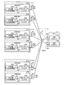
- FIG. 1 is a diagram showing a configuration example of a first embodiment of a PON system according to the present invention.
- FIG. 2 is a diagram illustrating a configuration example of a PON system in a case where a subscriber who implements duplexing and a subscriber who does not implement duplexing coexist.
- FIG. 3 is a diagram illustrating an example of a switching sequence from the A system to the B system.
- FIG. 4 is a diagram showing a configuration example of the second embodiment of the PON system according to the present invention.
- FIG. 5 is a diagram showing a configuration example of the third embodiment of the PON system according to the present invention.
- FIG. 6 is a diagram illustrating a configuration example of the PON system in the case where different wavelengths are used in the A system and the B system.
- 1,7 OLT 2 ODN 3 Splitter 4 Optical fiber 5-1 to 5-N, 6-1 to 6-N Subscriber premises equipment 8, 9-1 to 9-N L2SW 11a, 71a A series PON-LT 11b, 71b B system PON-LT 51a A series ONU 51b B system ONU 52a, 52b ONU side PON processing unit 53a, 53b, 72a, 72b Blocking filter 73a, 73b OLT side PON processing unit 101 uplink communication 102 A system downlink communication 103 B system downlink communication 104 A system uplink communication 105 B system uplink communication
- FIG. 1 is a diagram showing a configuration example of a first embodiment of a PON system according to the present invention.
- the PON system of this embodiment includes an OLT 1, an ODN (Optical Distribution Network) 2, a splitter 3 that is a 2: M optical splitter existing in the ODN 2, and the same subscriber's home.
- the subscriber premises devices 5-1 to 5-N (N is the number of subscribers), which is a group of installed devices, are connected between the OLT and the ODN, and the subscriber premises devices 5-1 to 5-N And an optical fiber 4 for connecting the ODNs.
- the subscriber premises apparatus 5-1 includes two systems of ONUs, an A-system ONU 51a and a B-system ONU 51b.
- the A-system ONU 51a includes an ONU-side PON processing unit 52a that performs user data termination processing, and a blocking filter 53a that blocks user data other than a specific wavelength (wavelength corresponding to the A-system).
- the B-system ONU 51b includes an ONU-side PON processing unit 52b that performs user data termination processing, and a blocking filter 53b that blocks user data other than a specific wavelength (wavelength corresponding to the B-system).
- the OLT 1 also includes an A-system PON-LT 11a that is an A-system PON-LT and a B-system PON-LT 11b that is a B-system PON-LT.
- the transmission method from the subscriber premises equipment 5-1 to 5-N to the OLT 1 is the upstream direction, and the transmission direction from the OLT 1 to the subscriber premises equipment 5-1 to 5-N is the same. It is defined as the down direction. 1 indicates uplink communication performed using the wavelength ⁇ up, the A-system downlink communication 102 indicates downlink communication performed using the wavelength ⁇ 1, and the B-system downlink communication 103 uses wavelength ⁇ 2.
- the A-system ONU 51a and the B-system ONU 51b are installed in the same subscriber's house where duplication is performed. Therefore, as shown in FIG. 1, one splitter 3 is shared by two systems of A system and B system.
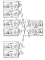
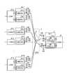
- FIG. 2 is a diagram illustrating a configuration example of a PON system in a case where a subscriber who implements duplexing and a subscriber who does not implement duplexing coexist.
- 6-1 to 6-N in FIG. 2 6-1 and 6-N are premises devices that perform duplication, and have the same configuration as the subscriber premises device 5-1 in FIG. is there.
- the subscriber premises device 6-2 and the subscriber premises device 6-3 are premises devices that do not perform duplication.
- the subscriber premises device 6-2 includes the A-system ONU 51a, and the subscriber premises device 6-3 is the B-system.
- An ONU 51b is provided.
- the same wavelength ⁇ up is assigned to all ONUs, and all ONUs communicate using this same wavelength ⁇ up regardless of whether they are A-system or B-system. Do. For example, 1470 nm which is a wavelength for 10G-EPON and 1310 nm which is a wavelength for GE-PON are assigned as ⁇ up.
- the TDMA (Time Division Multiple Access) system is used as the upstream multiplexing system of the A system and the B system, and the OLT 1 performs the allocation by the TDMA system, and the A system PON-LT 11a and the B system PON-LT 11b.
- the A line and the B line are secured by coordinating the bandwidth allocation performed by T and the time allocation of the A and B systems by the TDMA method.
- the bandwidth (allocation time) allocated to the A system and the bandwidth allocated to the B system reflecting the number of ONU systems (selected) for actual data communication (ONU system selection status).
- the bandwidth allocation ratio of (allocation time) is changed. Then, each of the ONU side PON processing unit 52a and the ONU side PON processing unit 52b transmits data during the communication time assigned to the corresponding system.
- two different wavelengths ⁇ 1 and ⁇ 2 are assigned to the A system and the B system, respectively.
- the wavelength 1577 nm for 10G-EPON is assigned to the A system
- 1490 nm which is the wavelength for GE-PON
- the A-system PON-LT 11a and the B-system PON-LT 11b transmit data using optical signals having wavelengths assigned to the corresponding systems.
- data using both wavelengths of the A system and the B system is transferred to the subscriber premises devices 5-1 to 5-N (or 6-1 to 6-N) arranged on the subscriber side. Therefore, it is assumed that blocking filters 53a and 53b that block other than the specific wavelength are provided.
- the standby ONU here, the B system is a standby system
- the two systems are the active system and the standby system, and when both the active system and the standby system are normal, the active system is used for data transmission / reception.
- the standby system is used only when there is a failure in the active system. If both the active system and the standby system are normal, the standby system may be used for data transmission / reception, but in this case, the active ONU also avoids the user frame from looping the network. For this reason, a function for blocking the user frame is provided.
- the A system is set as the active system, and data transmission is usually performed using the A system ONU (selecting the A system), and when a fault occurs in the A system, etc.
- Switch to the B system select the B system. Also, in a subscriber's home that does not support duplexing, since one ONU that supports only one of the A system and the B system is installed, switching due to the occurrence of a failure or the like is not performed.
- the uplink is time-division multiplexed, and different wavelengths are assigned to the A-line and the B-line on the downlink, so that a hot standby system in which the A-line and the B-line are always in operation can be adopted. Reliability can be improved and extra traffic can be accommodated.
- the switching time can be shortened, and both the A system and the B system can be constantly monitored, a failure occurs, and the system is switched from the A system to the B system. In this case, it is possible to avoid a situation in which the B system does not operate.
- the minimum unit for system switching can be set for each logical channel.
- the transmission speeds of the A system and the B system may be the same (for example, 10 Gbps for both the A system and the B system) or may be different (for example, the A system: 10 Gbps, the B system: 1 Gbps).
- the existing equipment GE-PON can be used for the B system. It becomes possible to raise. Specifically, for example, when a subscriber who has already joined the GE-PON newly joins the 10G-EPON system, the 10G-EPON system in which a new fiber is laid is used as the A system. By leaving the GE-PON as a backup line, the existing system can be used effectively.
- Ethernet (registered trademark) PS Protection Switching
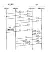
- FIG. 3 is a diagram illustrating an example of a switching sequence from the A system to the B system.
- FIG. 3 shows an example in which CC is used as a control frame for confirming the normality of the system and the occurrence of a failure is notified by RDI (Remote Defect Indication).
- RDI Remote Defect Indication
- the A system is selected and the user data is received from the A system PON-LT 11a of the OLT 1 (step S11).
- the A-system PON-LT 11a transmits the CC, and the A-system ONU 51a receives it (step S12). Then, the A-system ONU 51a returns the CC to the A-system PON-LT 11a (step S13).
- the B-system PON-LT 11b transmits the CC, and the B-system ONU 51b receives it (step S14). Then, the B system ONU 51b returns the CC to the B system PON-LT 11b (step S15).
- the A-system PON-LT 11a transmits a CC (step S16), and when a failure occurs (step S17), the A-system ONU 51a returns an RDI (step S18).
- the A-system PON-LT 11a transmits APS (Automatic Protection Switching) to the B-system PON-LT 11b (step S19).
- the B system PON-LT 11b returns the APS when the system can be switched (for example, when it is confirmed that the B system is normal by receiving the CC in step S14). (Step S20).
- the OLT 1 switches the system, the B system PON-LT 11b transmits the CC, and the B system ONU 51b receives it (step S21). Then, the B system ONU 51b returns the CC to the B system PON-LT 11b (step S22). After the CC is returned, the user data is transmitted from the B-system PON-LT 11b to the B-system ONU 51b (steps S23 and S24).
- the case of downlink communication has been described above, in the case of uplink communication, for example, the operation in the reverse direction may be performed.
- the subscriber premises equipment corresponding to duplexing includes two systems of ONUs A-system ONU 51a and B-system ONU 51b, and each is connected to the 2: M splitter 3 by the optical fiber 4.
- the same wavelength is assigned to the A system and the B system, and the A system and the B system are multiplexed by the TDMA method, and in the downstream communication, the A system and the B system are communicated at different wavelengths.
- the A system and the B system can be always operated, and both the system used for data transmission and the standby system can always be monitored by a control frame such as Ethernet (registered trademark) OAM. It is possible to prevent a situation in which the standby system does not operate after system switching. Therefore, one optical splitter can be utilized to the maximum, and high reliability can be realized at low cost. Further, in this embodiment, extra traffic can be accommodated, and the usable bandwidth can be expanded at the normal time when no failure occurs.
- the user frame on the standby side is blocked so that the user frame does not loop the system, but the standby ONU (in the above example, The ONU 51b) may be forcibly blocked by some means (forced link down) to avoid a loop.
- the system is two systems, but is not limited to this, and may be three systems or more.
- communication is performed by assigning a different wavelength for each system for downlink communication, and for uplink communication, data of each system may be multiplexed by the TDMA method.
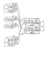
- FIG. FIG. 4 is a diagram showing a configuration example of the second embodiment of the PON system according to the present invention.
- the configuration of the PON system of the present embodiment is the same as that of the PON system of the first embodiment except that OLT 1 is replaced with OLT 7.
- Components having the same functions as those in the first embodiment are denoted by the same reference numerals and description thereof is omitted.
- the OLT 7 is composed of an A-system PON-LT 71a and a B-system PON-LT 71b.
- the A-system PON-LT 71a includes a blocking filter 72a that blocks user data other than a specific wavelength (wavelength corresponding to the A-system), and an OLT-side PON processing unit 73a that performs user data termination processing.
- the B-system PON-LT 71b includes a blocking filter 72b that blocks user data other than a specific wavelength (wavelength corresponding to the B system), and an OLT-side PON processing unit 73b that performs user data termination processing.
- the uplink communication 105 represents the B-system uplink communication performed using the wavelength ⁇ up2.
- the same wavelength is used in both the A system and the B system in the upstream direction, but in this embodiment, different wavelengths are used in the A system and the B system. For example, 1270 nm for 10G-EPON is used for the A system, and 1310 nm for GE-PON is used for the B system.
- data is transmitted using each wavelength in the same manner as the downlink communication according to the first embodiment.
- the redundant system PON-LT blocks the user frame on the standby side so that the user frame does not loop the system. In this embodiment, it is not necessary to perform time-division multiplexing of A-system and B-system data, so that the use band can be increased even in the uplink.
- strain is made into 2 lines
- FIG. FIG. 5 is a diagram showing a configuration example of the third embodiment of the PON system according to the present invention.
- the PON system is the same as that of the first embodiment except that an L2SW 9-i to be connected to is added.
- Components having the same functions as those in the first embodiment are denoted by the same reference numerals and description thereof is omitted.
- control frames such as Ethernet (registered trademark) OAM are transmitted and received between the OLT 1 and the ONUs 5-1 to 5-N (or ONUs 6-1 to 6-N).
- the upper L2SW2 is the end of the control frame.
- the L2SW 7 of this embodiment is connected to each of the A-system PON-LT 11a and the B-system PON-LT 11b, and the L2SW 9-i is connected to the A-system and the B-system when the subscriber premises device 6-i supports duplexing. Are connected to each other, and if they do not support duplication, they are connected to either the ONU 51a or ONU 51b in the subscriber premises equipment 6-i.
- monitoring and fault detection performed between the OLT 1 and the ONUs 5-1 to 5-N (or ONUs 6-1 to 6-N) are performed between the L2SW2 and the L2SW 9-i.
- the other operations in this embodiment are the same as those in the first embodiment.
- FIG. 6 is a diagram illustrating a configuration example of the PON system in the case where different wavelengths are used in the A system and the B system.
- the configuration of the PON system in the example of FIG. 6 is the same as that of the second embodiment except that the L2SW 8 and the L2SW 9-i are added.
- the operation is the same as in the example of FIG. 5 except that different wavelengths are used for the A system and the B system.
- control frame for monitoring the A system and the B system is performed between the L2SW 8 and the L2SW 9-i. For this reason, the same processing as in the first embodiment or the second embodiment can be performed without increasing the load on the OLT 1.
- the L2SW 8 or L2SW 9-i may select not only the transmission and reception of control frames for monitoring the A system and the B system but also the selection of the A system and the B system.
- the PON system and the redundancy method according to the present invention are useful for a PON system that implements redundancy, and are particularly suitable for a PON system that achieves high reliability while reducing costs.
Landscapes
- Engineering & Computer Science (AREA)
- Computer Networks & Wireless Communication (AREA)
- Signal Processing (AREA)
- Physics & Mathematics (AREA)
- Electromagnetism (AREA)
- Small-Scale Networks (AREA)
- Optical Communication System (AREA)
Priority Applications (6)
| Application Number | Priority Date | Filing Date | Title |
|---|---|---|---|
| US13/060,947 US8615169B2 (en) | 2008-08-26 | 2008-08-26 | PON system and redundancy method |
| CN200880130869.0A CN102132529B (zh) | 2008-08-26 | 2008-08-26 | Pon系统以及冗余化方法 |
| JP2010526443A JP5204234B2 (ja) | 2008-08-26 | 2008-08-26 | Ponシステムおよび冗長化方法 |
| EP08809321.6A EP2320607A4 (en) | 2008-08-26 | 2008-08-26 | PON SYSTEM AND REDUNDANCY PROCESS |
| KR1020117004293A KR101237687B1 (ko) | 2008-08-26 | 2008-08-26 | Pon 시스템 및 리던던시화 방법 |
| PCT/JP2008/065174 WO2010023721A1 (ja) | 2008-08-26 | 2008-08-26 | Ponシステムおよび冗長化方法 |
Applications Claiming Priority (1)
| Application Number | Priority Date | Filing Date | Title |
|---|---|---|---|
| PCT/JP2008/065174 WO2010023721A1 (ja) | 2008-08-26 | 2008-08-26 | Ponシステムおよび冗長化方法 |
Publications (1)
| Publication Number | Publication Date |
|---|---|
| WO2010023721A1 true WO2010023721A1 (ja) | 2010-03-04 |
Family
ID=41720910
Family Applications (1)
| Application Number | Title | Priority Date | Filing Date |
|---|---|---|---|
| PCT/JP2008/065174 WO2010023721A1 (ja) | 2008-08-26 | 2008-08-26 | Ponシステムおよび冗長化方法 |
Country Status (6)
| Country | Link |
|---|---|
| US (1) | US8615169B2 (zh) |
| EP (1) | EP2320607A4 (zh) |
| JP (1) | JP5204234B2 (zh) |
| KR (1) | KR101237687B1 (zh) |
| CN (1) | CN102132529B (zh) |
| WO (1) | WO2010023721A1 (zh) |
Cited By (3)
| Publication number | Priority date | Publication date | Assignee | Title |
|---|---|---|---|---|
| JP2014078797A (ja) * | 2012-10-09 | 2014-05-01 | O F Networks Co Ltd | 冗長システム、光通信装置及び親局装置 |
| JP2017147743A (ja) * | 2017-04-10 | 2017-08-24 | 沖電気工業株式会社 | 冗長システム、親局装置及び子局装置 |
| JP2018500844A (ja) * | 2014-12-30 | 2018-01-11 | 華為技術有限公司Huawei Technologies Co.,Ltd. | 多波長パッシブ光ネットワークに適用される通信方法、装置、及びシステム |
Families Citing this family (13)
| Publication number | Priority date | Publication date | Assignee | Title |
|---|---|---|---|---|
| US9106984B2 (en) | 2009-08-21 | 2015-08-11 | Mitsubishi Electric Corporation | PON system, subscriber-side terminal apparatus, station-side terminal apparatus, and power saving method |
| US20140199062A1 (en) * | 2011-05-17 | 2014-07-17 | Telefonaktiebolaget L M Ericsson (Publ) | Protection for Fibre Optic Access Networks |
| JP6064907B2 (ja) * | 2011-09-02 | 2017-01-25 | 日本電気株式会社 | ノード装置およびその制御方法と制御プログラム |
| US8953936B2 (en) * | 2012-10-01 | 2015-02-10 | Telefonaktiebolaget L M Ericsson (Publ) | Method for protection of multi-wavelength passive optical network |
| CN105009483B (zh) * | 2013-03-08 | 2017-06-30 | 富士通株式会社 | 光网络系统和光通信方法 |
| WO2014189953A1 (en) * | 2013-05-20 | 2014-11-27 | Huawei Technologies Co., Ltd. | Cooperative multi-point (comp) in a passive optical network (pon) |
| US9179203B2 (en) * | 2013-09-30 | 2015-11-03 | Verizon Patent And Licensing Inc. | Optical network system architecture |
| US10009095B2 (en) * | 2014-03-24 | 2018-06-26 | Telefonaktiebolaget Lm Ericsson (Publ) | Protection switching across interconnecting node |
| US9960840B2 (en) | 2014-09-15 | 2018-05-01 | Arris Enterprises Llc | Intra-chassis protection systems and methods for passive optical network optical line terminals |
| WO2017192894A1 (en) * | 2016-05-04 | 2017-11-09 | Adtran, Inc. | Systems and methods for performing optical line terminal (olt) failover switches in optical networks |
| US10200123B2 (en) * | 2016-06-20 | 2019-02-05 | Cable Television Laboratories, Inc. | System and methods for distribution of heterogeneous wavelength multiplexed signals over optical access network |
| US10397672B2 (en) * | 2016-06-20 | 2019-08-27 | Cable Television Laboratories, Inc. | Systems and methods for intelligent edge to edge optical system and wavelength provisioning |
| US20230412265A1 (en) * | 2022-06-14 | 2023-12-21 | Mellanox Technologies, Ltd. | Transceiver module |
Citations (4)
| Publication number | Priority date | Publication date | Assignee | Title |
|---|---|---|---|---|
| JPH09284325A (ja) | 1996-04-12 | 1997-10-31 | Nec Corp | スター形光加入者伝送装置 |
| JPH11122172A (ja) * | 1997-10-20 | 1999-04-30 | Fujitsu Ltd | 光加入者ネットワークシステム |
| JP2001203639A (ja) * | 2000-01-19 | 2001-07-27 | Hitachi Ltd | 光伝送システムおよび伝送路の切替え方法 |
| JP2002077212A (ja) * | 2000-09-01 | 2002-03-15 | Mitsubishi Electric Corp | 光多分岐通信システム |
Family Cites Families (10)
| Publication number | Priority date | Publication date | Assignee | Title |
|---|---|---|---|---|
| US5539564A (en) * | 1993-09-22 | 1996-07-23 | Nippon Telegraph And Telephone Corporation | Point-to-multipoint optical transmission system |
| JPH088820A (ja) | 1994-06-15 | 1996-01-12 | Nippon Telegr & Teleph Corp <Ntt> | ポイント・マルチポイント伝送方式 |
| JP3510059B2 (ja) | 1996-10-21 | 2004-03-22 | 富士通株式会社 | 交差型二重化構成を有するパッシブダブルスター通信システム |
| JP3350926B2 (ja) * | 1999-03-30 | 2002-11-25 | 日本電気株式会社 | Ponのプロテクション切り換え方法および装置 |
| US6868232B2 (en) * | 2001-02-12 | 2005-03-15 | Lucent Technologies Inc. | Fast protection switching by snooping on upstream signals in an optical network |
| JP3888130B2 (ja) | 2001-11-01 | 2007-02-28 | セイコーエプソン株式会社 | 無線ネットワークのステーション |
| WO2006116895A1 (en) * | 2005-04-29 | 2006-11-09 | Zte Corporation | Passive optical network system based on wavelength protection and protecting backup method thereof |
| JP4728697B2 (ja) | 2005-05-17 | 2011-07-20 | 日本電気株式会社 | 光スイッチ装置及びそれを用いた光アクセスネットワーク方法と光アクセスネットワークシステム |
| JP4704842B2 (ja) * | 2005-08-01 | 2011-06-22 | 株式会社日立製作所 | Wdm型ponシステム |
| JP2007151195A (ja) | 2007-03-12 | 2007-06-14 | Brother Ind Ltd | 無線lanシステム,通信端末および通信プログラム |
-
2008
- 2008-08-26 JP JP2010526443A patent/JP5204234B2/ja not_active Expired - Fee Related
- 2008-08-26 WO PCT/JP2008/065174 patent/WO2010023721A1/ja active Application Filing
- 2008-08-26 US US13/060,947 patent/US8615169B2/en not_active Expired - Fee Related
- 2008-08-26 KR KR1020117004293A patent/KR101237687B1/ko not_active IP Right Cessation
- 2008-08-26 CN CN200880130869.0A patent/CN102132529B/zh not_active Expired - Fee Related
- 2008-08-26 EP EP08809321.6A patent/EP2320607A4/en not_active Withdrawn
Patent Citations (4)
| Publication number | Priority date | Publication date | Assignee | Title |
|---|---|---|---|---|
| JPH09284325A (ja) | 1996-04-12 | 1997-10-31 | Nec Corp | スター形光加入者伝送装置 |
| JPH11122172A (ja) * | 1997-10-20 | 1999-04-30 | Fujitsu Ltd | 光加入者ネットワークシステム |
| JP2001203639A (ja) * | 2000-01-19 | 2001-07-27 | Hitachi Ltd | 光伝送システムおよび伝送路の切替え方法 |
| JP2002077212A (ja) * | 2000-09-01 | 2002-03-15 | Mitsubishi Electric Corp | 光多分岐通信システム |
Non-Patent Citations (1)
| Title |
|---|
| See also references of EP2320607A4 |
Cited By (4)
| Publication number | Priority date | Publication date | Assignee | Title |
|---|---|---|---|---|
| JP2014078797A (ja) * | 2012-10-09 | 2014-05-01 | O F Networks Co Ltd | 冗長システム、光通信装置及び親局装置 |
| JP2018500844A (ja) * | 2014-12-30 | 2018-01-11 | 華為技術有限公司Huawei Technologies Co.,Ltd. | 多波長パッシブ光ネットワークに適用される通信方法、装置、及びシステム |
| US10123101B2 (en) | 2014-12-30 | 2018-11-06 | Huawei Technologies Co., Ltd. | Communication method applied to multi-wavelength passive optical network, apparatus, and system |
| JP2017147743A (ja) * | 2017-04-10 | 2017-08-24 | 沖電気工業株式会社 | 冗長システム、親局装置及び子局装置 |
Also Published As
| Publication number | Publication date |
|---|---|
| KR20110046493A (ko) | 2011-05-04 |
| US8615169B2 (en) | 2013-12-24 |
| EP2320607A1 (en) | 2011-05-11 |
| US20110158638A1 (en) | 2011-06-30 |
| EP2320607A4 (en) | 2016-05-11 |
| JPWO2010023721A1 (ja) | 2012-01-26 |
| JP5204234B2 (ja) | 2013-06-05 |
| CN102132529A (zh) | 2011-07-20 |
| KR101237687B1 (ko) | 2013-02-26 |
| CN102132529B (zh) | 2014-06-18 |
Similar Documents
| Publication | Publication Date | Title |
|---|---|---|
| JP5204234B2 (ja) | Ponシステムおよび冗長化方法 | |
| US10735836B2 (en) | Passive optical network communications method, apparatus and system | |
| US7174096B2 (en) | Method and system for providing protection in an optical communication network | |
| CN101826919B (zh) | 一种混合型无源光网络及其故障定位和恢复的方法 | |
| JP3799037B2 (ja) | 切替型メディア変換器とこれを含む上下向同一波長のリング型wdmponシステム | |
| JP5058910B2 (ja) | ポイント−マルチポイントシステムにおける冗長化伝送システム | |
| EP1496634A2 (en) | Self-healing wavelength division multiplexing passive optical network system | |
| US20060250681A1 (en) | Inter-network optical fiber sharing system | |
| JP5335952B2 (ja) | ポイント−マルチポイントシステムにおける冗長化伝送システム | |
| CN201674613U (zh) | 一种具有保护功能的混合无源光网络结构 | |
| JP6285611B2 (ja) | 局側装置及び波長切替監視方法 | |
| Kanungoe et al. | A new protection scheme for a combined ring-star based hybrid WDM/TDM PON architecture | |
| JP6413484B2 (ja) | 局側終端装置、光アクセスネットワーク及び通信方法 | |
| JP4905076B2 (ja) | 局側装置 | |
| EP2517390B1 (en) | Method and device for data protection in an optical communication network | |
| Sue | Opn01-1: 1: n protection scheme for awg-based wdm pons | |
| JP2010239552A (ja) | 光伝送システム | |
| KR102034268B1 (ko) | 예비회선을 제공하는 wdm 기반 pon 거리 확장 장치 | |
| KR101013722B1 (ko) | 파장분할다중-수동광통신망의 통신채널 절체 시스템 및 방법 | |
| JP2002009803A (ja) | 通信ネットワーク、通信ネットワーク・ノード装置、及び、障害回復方式 | |
| TWI450506B (zh) | 被動式光纖網路架構與保護方法及光開關結構 | |
| JP2001203639A (ja) | 光伝送システムおよび伝送路の切替え方法 | |
| KR20080087376A (ko) | 고밀도 파장분할 다중화를 이용한 수동형 광가입자망의보호절체 방식 |
Legal Events
| Date | Code | Title | Description |
|---|---|---|---|
| WWE | Wipo information: entry into national phase |
Ref document number: 200880130869.0 Country of ref document: CN |
|
| 121 | Ep: the epo has been informed by wipo that ep was designated in this application |
Ref document number: 08809321 Country of ref document: EP Kind code of ref document: A1 |
|
| WWE | Wipo information: entry into national phase |
Ref document number: 2010526443 Country of ref document: JP |
|
| ENP | Entry into the national phase |
Ref document number: 20117004293 Country of ref document: KR Kind code of ref document: A |
|
| WWE | Wipo information: entry into national phase |
Ref document number: 13060947 Country of ref document: US |
|
| NENP | Non-entry into the national phase |
Ref country code: DE |
|
| WWE | Wipo information: entry into national phase |
Ref document number: 2008809321 Country of ref document: EP |