WO2010021273A1 - 発光装置及び対象物の追尾方法 - Google Patents
発光装置及び対象物の追尾方法 Download PDFInfo
- Publication number
- WO2010021273A1 WO2010021273A1 PCT/JP2009/064179 JP2009064179W WO2010021273A1 WO 2010021273 A1 WO2010021273 A1 WO 2010021273A1 JP 2009064179 W JP2009064179 W JP 2009064179W WO 2010021273 A1 WO2010021273 A1 WO 2010021273A1
- Authority
- WO
- WIPO (PCT)
- Prior art keywords
- light
- color
- emitting device
- data
- change
- Prior art date
- Legal status (The legal status is an assumption and is not a legal conclusion. Google has not performed a legal analysis and makes no representation as to the accuracy of the status listed.)
- Ceased
Links
Images


Classifications
-
- H—ELECTRICITY
- H04—ELECTRIC COMMUNICATION TECHNIQUE
- H04B—TRANSMISSION
- H04B10/00—Transmission systems employing electromagnetic waves other than radio-waves, e.g. infrared, visible or ultraviolet light, or employing corpuscular radiation, e.g. quantum communication
- H04B10/11—Arrangements specific to free-space transmission, i.e. transmission through air or vacuum
- H04B10/114—Indoor or close-range type systems
- H04B10/1141—One-way transmission
-
- G—PHYSICS
- G01—MEASURING; TESTING
- G01S—RADIO DIRECTION-FINDING; RADIO NAVIGATION; DETERMINING DISTANCE OR VELOCITY BY USE OF RADIO WAVES; LOCATING OR PRESENCE-DETECTING BY USE OF THE REFLECTION OR RERADIATION OF RADIO WAVES; ANALOGOUS ARRANGEMENTS USING OTHER WAVES
- G01S5/00—Position-fixing by co-ordinating two or more direction or position line determinations; Position-fixing by co-ordinating two or more distance determinations
- G01S5/16—Position-fixing by co-ordinating two or more direction or position line determinations; Position-fixing by co-ordinating two or more distance determinations using electromagnetic waves other than radio waves
-
- H—ELECTRICITY
- H04—ELECTRIC COMMUNICATION TECHNIQUE
- H04B—TRANSMISSION
- H04B10/00—Transmission systems employing electromagnetic waves other than radio-waves, e.g. infrared, visible or ultraviolet light, or employing corpuscular radiation, e.g. quantum communication
- H04B10/11—Arrangements specific to free-space transmission, i.e. transmission through air or vacuum
- H04B10/114—Indoor or close-range type systems
- H04B10/116—Visible light communication
Definitions
- the present invention relates to a light emitting device in which a change in emitted color changes according to data.
- the present invention relates to a light emitting device that expresses data by a change in color change.
- this light-emitting device is a light-emitting device that is attached to an object and used for displaying and communicating predetermined data along with tracking of the object.
- Conventional communication means using light generally encodes and transmits data using a combination of time lengths of light intensity (blinking, blinking, etc.).
- the inventor of the present application has invented a mechanism capable of transmitting the position of a light emitter while displaying data using a light emitter whose color changes in a specific pattern.
- the inventor of the present application has proposed a technique for representing data by a change in color and representing a position by the change in color.
- a technique for extracting and selecting a certain shape or color change from a still image by an image processing technique is used.
- a technique for tracking changes in a certain shape or color from a moving image is used.
- the characteristics of the image used for the tracking technique need to be constant.
- the tracking target generally needs to be a certain pattern.
- the expression of various data and the detection of the position are generally contradictory events, and it is possible to track only with the optical image, and the position of the light emission pattern can be determined while specifying the position in the image.
- a static optical automatic recognition code such as a barcode symbol.
- each still image in the moving image is cut out, a bar code pattern is searched for each still image, and is decoded and decoded to obtain original data.
- the original data can be decoded (decoded) while tracking and detecting the position.
- a system capable of performing data communication and specifying a position on the premise of a moving image of such quality can provide a system that is extremely convenient and can be applied to various applications.
- the present invention has been made under such a background, and an object of the present invention is to provide a system capable of tracking a target while realizing a practical data transfer amount.
- optical automatic recognition code such as a barcode
- predetermined data such as an ID to an article (called an article to be marked).
- optical automatic recognition codes such as the above-described barcode are widely used.
- RFID using electromagnetic waves has also been used. The optical recognition code optically reads a predetermined mark and obtains original data. If the code exists in a visually visible range, the data can be read.
- RFID is an electromagnetic wave that reads original data from the RFID, and can be read even when the RFID is visually hidden.
- an optical automatic recognition code is generally used for a product.
- the optical automatic recognition code the above-described barcode or color barcode is used.
- the bar code is a code consisting of two colors, a white bar and a black bar, and various optical recognition codes using more types of colors (red, blue, yellow, etc.) including chromatic colors have been proposed. .
- the inventors of the present invention have also proposed a color barcode called “1D color bit code” in a patent application (Japanese Patent Application No. 2006-196705, etc.).
- the optical recognition code including the term chromatic color is referred to as a “color barcode”.
- bar code it represents a classic bar code of a white bar and a black bar.
- the optical recognition code is often attached to the object itself, its container or packaging. This action is called “marking”.
- An object / means that has been marked and embodied is generally called a “medium”.
- “ink” used when marking an object with an optical recognition code is a suitable example of the medium.
- the object is clothing or the like, a cardboard “tag” or the like is used, and an optical recognition code such as a barcode is often displayed on the tag.
- the “tag” is a suitable example of the medium.
- the object may be particularly referred to as a “marked object”.
- optical recognition codes other than light display data using “light”, but means for representing data using other physical means are also known.
- Examples of communication There is a field of data “communication” technology as a technology related to a technology for “displaying” data. From the viewpoint of this data communication technique, many examples using other physical means are known.
- optical communication using an optical fiber is known as means using light in the same manner as an optical recognition code.
- communication means using various lights such as infrared light, laser light, and visible light are known even if simply referred to as “light”.
- the optical recognition code not only the "Display” of the data, itself be used in applications to recognize the "position” of the object are known from the prior art.
- Patent Documents 1 and 2 there is a position measurement / data communication system using infrared rays as a medium.
- Patent Document 1 is provided with a light emitting member for position display and a light emitting member for data transmission, photographing the light emission state by an imaging means, measuring the position from the image, and blinking the light emitting member. Discloses a position measurement / data communication system for performing data communication.
- a marker and an individual identification code output means are provided, and the individual identification code is transmitted by infrared rays, electromagnetic waves, etc., and at the same time as the individual identification code is transmitted, the marker luminance / hue changes in a predetermined pattern.
- a position detection system that determines the position of an individual simultaneously with reception of the individual identification code.
- the present invention uses a normal CCD camera / video camera, (1)
- the position of the object can be easily specified optically, (2)
- One of the purposes is to realize a device that can reliably communicate data.
- the present invention pays attention to “color change” and attempts to realize the above object by devising this.
- the purpose is to provide technology.
- LEDs that can change the emission color are generally well known and are called full color LEDs. It is easy to change the color of such a full-color LED, obtain it as a picture with a CCD camera, and display it on a monitor.
- a tracking technique a technique for tracking the same color, and a technique for tracking a moving object in an image based on an image difference are widely known and common.
- the above-described LED is not always captured by the CCD camera for some reason, and it is common to see that an equivalent color exists in the surroundings. Therefore, it is considered difficult to track an object whose color changes if the conventional technique of tracking an object using color as a clue is used as it is.
- FIG. 1 is a sequence diagram showing a sequence in which three color LEDs are turned on / off, and the horizontal axis represents time. These three colors of RGB LEDs will be described below assuming that they constitute full-color LEDs.
- the full-color LED is an LED device that can emit light of any color by appropriately turning on / off these three color LEDs.
- the notation method is defined.
- R and G are alternately turned on / off repeatedly, that is, when R is turned on, G is turned on (R is turned off), R is turned on (G is turned off), G is turned on (R is turned off), and R is turned on (G is turned off).
- G and B are alternately turned on / off repeatedly, G * B Is described.
- the LED changes in the order of R * G ⁇ G * B ⁇ B * R ⁇ R * G ⁇ B * R ⁇ R * G.
- this “change in color change” may be referred to as “color change change” for convenience, but the substance does not change as “change change”.
- a pattern in which predetermined colors are periodically exchanged and lit as a color change will be described.
- a change in the color used is a “change in change”.
- the light emission pattern of the color changes it may be referred to as “the light emission pattern is switched”.
- data “1” and “0” are assigned as follows.
- Data “1” is assigned to R * G ⁇ G * B, G * B ⁇ B * R, and B * R ⁇ R * G.
- “0” of data is assigned to G * B ⁇ R * G, B * R ⁇ G * B, and R * G ⁇ B * R.
- G * B ⁇ R * G, B * R ⁇ G * B, and R * G ⁇ B * R When such a change of the color change state occurs, it represents “1”.
- the present invention represents data by “change in color change (change change)”
- the object is specified and the position is specified by the first primary change.
- Data is represented by the next change (switching of the first change).
- the present invention is based on the principle of switching the periodic change of the color, but this period represents a unit period in which the color changes and may be any time.
- this period is longer than the frame period of the image of the video camera.
- the period may be called a cycle.
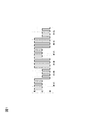
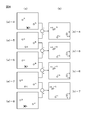
- FIGS. 3 to 4 show examples in which five bright spots exist (fixed position).
- the emission color of each of the five bright spots changes.
- 3-4 the time flows from top to bottom, and the continuation of FIG. 3 is depicted in FIG.
- Each screen along the flow of time is described in FIG. 3A and the continuation of FIG. 4A.
- the difference image of each image is described in FIG. 3B and FIG. 4B.
- FIG. 3A-1 shows an example in which there are four bright spots in addition to the target bright spot of the R color.
- the example in FIGS. 3 to 4 is an explanatory diagram when the bright spot does not move (when it moves, it will be described later).
- the lower left luminescent spot has the R color as in the target luminescent spot, and is the luminescent spot of the blinking light. That is, in (a) -1, (a) -3, and (a) -5, this bright spot is lit, and in (a) -2, (a) -4, and (a) -6, The bright spot is off.
- ⁇ indicates that each bright spot is turned on, and when X is superimposed on ⁇ , it indicates that it is turned off.
- FIG. 3 shows a case where the brightness of the target bright spot is reduced for some reason and the light is extinguished.
- the difference image (b) -1 between (a) -2 and (a) -1 two bright spots of the color ⁇ R appear (see FIG. 3B-1). Among these, one is the focused bright spot as described above, and the other is the above-mentioned blinking bright spot at the lower left.
- the brightness of the target bright spot is returned and light is emitted again with R.
- the blinking lower left bright spot described above becomes brighter again by blinking and emits light with R.
- the difference image (b) -2 between (a) -3 and (a) -2 shows two bright spots of + R color (see FIG. 3 (b) -2). Similarly, one is a bright spot of interest and the other is a blinking bright spot in the lower left.
- FIG. 3 The continuation of FIG. 3 is shown in FIG.
- (A) -4 in FIG. 4 is a continuation of (a) -3 in FIG. 3, and the pixel of interest changes in color to G (green). Also, the blinking luminescent spot in the lower left is turned off.
- the difference image (b) -3 (drawn in both FIGS. 3 and 4) between (a) -4 and (a) -3, the pixel of interest is GR, and the lower left blinks.
- the bright spot is -R.
- the target pixel remains G (green) emission, and the blinking bright spot at the lower left is in the on state from the off state.
- the difference image (b) -4 (FIG. 4) between (a) -5 and (a) -4 disappears because the pixel of interest is the same color.
- the blinking bright spot in the lower left is + R.
- the target illuminant when the “signal illuminant” moves, the target illuminant can be detected by using a difference image in principle. Similarly, other non-target light emitters are also detected, so that the specific processing becomes complicated.
- 5 to 6 show a case where a plurality of bright spots are included in one image, as in FIGS. 3 to 4. In particular, FIGS. 5 to 6 show a situation where the bright spot moves.
- FIG. 5 (a) -1 there are two bright spots other than the focused bright spot (the bright spot at the upper left), and there are a total of three bright spots on the screen.
- the bright spot at the lower right is the G color and the bright spot of the blinking light.
- the bright spot at the right end is the bright spot of the color B, does not blink, and there is no change in color.
- the example shown in FIGS. 5 to 6 is an example in which all the bright spot points including the target bright spot move.
- the flashing lower right bright spot is (a) -1, (a) -3, (a) -5, (a) -7, and this bright spot is lit. ) -2, (a) -4, (a) -6, and (a) -8, the bright spot is extinguished.
- a circle indicates that each bright spot is lit, and a circle indicates that it is extinguished.
- (A) -2 in FIG. 5 shows a case where the brightness of the target bright spot is reduced for some reason and the light is extinguished.
- the lower right bright spot is extinguished as described above.
- the difference image (b) -1 between (a) -2 and (a) -1 first, a bright spot with a difference between + B and -b appears at the right end. This is because the bright spot of B moved from (a) -1 to (a) -2.
- a difference of ⁇ b appears at the position before the movement, and a difference of + B appears at the position before the movement.
- the brightness of the target bright spot is returned and light is emitted again with R. Further, the blinking lower left bright spot described above becomes brighter again by blinking, and emits G light.
- the difference image (b) -2 between (a) -3 and (a) -2 first, the bright spot of the difference between + B and -b appears at the right end. This is because the bright spot of B moved further from (a) -2 to (a) -3. A difference of ⁇ b appears at the position before the movement, and a difference of + B appears at the position before the movement. This is the same as the difference image (b) -2.
- the leftmost R bright spot and the lower right G bright spot appear again compared to (a) -2, so in the difference image (b) -2, + R , + G difference bright spots appear.
- FIG. (A) -5 in FIG. 6 is a continuation of (a) -4 in FIG. 5, and the pixel of interest continues to emit light while maintaining the G color.
- the blinking bright spot at the lower left is now in the lighting state (G).
- FIG. 6 (a) -4 and (b) -4 in FIG. 5 are shown again.
- the difference image (b) -4 (drawn in both FIG. 5 and FIG. 6) between (a) -5 and (a) -4 is the difference between + B and ⁇ b at the right end as before.
- the bright spot appears. This is because the bright spot of B moved further from (a) -4 to (a) -5.
- a difference of ⁇ B appears at the position before the movement, and a difference of + B appears at the position before the movement. This is the same as the difference images (b) -2 and (b) -3.
- the target pixel continues to emit light while maintaining the G color.
- the blinking bright spot at the lower left is now turned off.
- the difference image (b) -5 between (a) -6 and (a) -5 the bright spot of the difference between + B and -B appears at the right end as before.
- the leftmost bright spot is moved as compared with (a) -5. Therefore, in the difference image (b) -5, similarly to the above, bright spots with a difference of + G and -G respectively appear.
- the difference image (b) -5 as described above, since the lower G bright spot is turned off, in the difference image (b) -5, the -G bright spot appears.
- the pixel of interest continues to emit light while maintaining the G color.
- the blinking bright spot in the lower left is now lit.
- the difference image (b) -6 between (a) -7 and (a) -6 the bright spot of the difference between + B and -B appears at the right end as before.
- a bright spot with a difference of + G and ⁇ G appears at the left end.
- the + G bright spot appears in the difference image (b) -6.
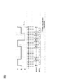
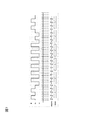
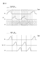
- R * G: 0, B * R: 1, G * B: 2 Explain the case. That is, “0” is assigned when the color changes between R and G (periodically changes) as in RGRGRGRG .... Similarly, “1” is assigned to changes in B and R, and “2” is assigned to changes in G and B. That is, data is represented by a ternary number.
- FIG. 7 An example of light emission in such a case is shown in FIG.
- a sequence in which each color of RGB emits light is shown, and only one of RGB colors emits light at a time.
- the light emission sequence is sampled at a sampling period indicated by a two-dot chain line in FIG. 7 to detect the color being emitted.
- the detected color is shown in the lower stage of the two-dot chain line. Further, in the lowermost part of FIG. 7, the value of data obtained as a result of the detection is described.
- R * G when R * G continues, if the color of G approaches the threshold value of B, the distinction from R * B becomes unclear.
- R and G are properly spaced at an interval of 0, and the colors may not be interchanged instantaneously but may be mixed. From the capture side (reading side), if the signal color changes during the exposure time, it is difficult in principle to avoid color mixing in the detected color, and the background color is mixed there. Thus, it is not always possible to read the same alternating lighting for a long time as the same data.
- the captured screen (taken and captured by a computer or the like), it is always possible to recognize the color change when considering specific image processing of the signal light emitter. This is because the sampling period is determined so that the color change period is twice or more the sampling period. Therefore, the signal light emitter can be specified using the detected color change. That is, it turns out that there is a signal light emitter at that position and the color is periodically changed.
- a color that is not used in the next repeated light emission may come to the last color of the repetition.
- the light emission changes sequentially as “RGRGRGBRBR”. This changed from R * G to B * R.
- G * B appears to exist for a moment between the repetition of R * G and the repetition of B * R (boundary portion). This may cause a reading error.
- FIG. 8 shows the state when the data is represented in the direction of color change.
- the present invention employs the following means.
- the present invention includes a light emitter capable of emitting at least three kinds of colors, and a control unit that periodically changes colors emitted from the light emitter,
- the means is a light emitting device characterized in that the periodic color change is switched based on predetermined data, and the predetermined data is represented by the periodic color change switching.
- the color change is a color change that alternately emits two different colors, and the switching is at least one of the colors that emit alternately.
- the light emitting device is characterized in that one of the colors is changed to another color.
- the present invention also provides a first illuminant capable of emitting at least three colors, a second illuminant, and colors emitted by the first illuminant and the second illuminant.
- Control means for periodically changing the control means wherein the control means switches the periodic color change based on predetermined data, and represents the predetermined data by switching the periodic color change,
- the control means controls the periodic color change of the first light emitter and the periodic color change of the second light emitter to be different color changes.
- the color change is a color change that alternately emits two different colors, and the switching is at least one of the colors that emit light alternately.
- the light emitting device is characterized in that one of the colors is changed to another color.
- the different color change includes a color change in which at least one of the alternately emitted colors is different. Device.
- the control unit is configured to perform the first light emission.
- the light-emitting device is controlled so that the body and the second light-emitting body do not emit the same color at the same time.
- the different color changes include a color change that alternately emits the same color but a different light emission timing.
- the light-emitting device is controlled so that the first light-emitting body and the second light-emitting body do not emit the same color at the same time.
- the present invention provides n first light emitters that can emit at least three colors,... Nth light emitter, and the first to nth light emitters.
- Control means for periodically changing the colors emitted by the illuminant and the control means switches the periodic color change based on predetermined data, and the periodic color change is switched.
- the light-emitting device represents the predetermined data, and the control unit controls the periodic color changes of the first to n-th light emitters to be different from each other.
- n is a positive integer of 2 or more.
- the color change is a color change that alternately emits two different colors, and the switching is at least one of the colors that alternately emit light.
- the light emitting device is characterized in that one of the colors is changed to another color.
- the present invention provides the light emitting device according to (9), wherein the different color change includes (a) at least one of the alternately emitted colors, and the color change (b) alternately.
- a light-emitting device characterized in that it includes both color changes that emit the same color but different timings of light emission.
- the present invention provides m first to m-th light emitters capable of emitting at least three colors and the first to m-th light emission.
- Control means for periodically changing the colors emitted by the body and the control means switches the periodic color change based on a predetermined ID, and by switching the periodic color change, It represents the ID of the light device or the ID of the object to which the light emitting device is attached, and the control means switches the periodic color change based on predetermined data, and the periodic color change
- the light emitting device represents the predetermined data by switching.
- m is a positive integer of 1 or more.
- the present invention provides an ID pattern composed of color change groups switched to represent the ID and a data pattern composed of color change groups switched to represent the data. And a margin pattern that represents a margin that does not represent the ID and the data, a frame that is a unit of communication is configured, and the control means displays and transmits data in units of this frame.
- the light emitting device is characterized by controlling the light emitter.
- the blank pattern is alternately switched between a predetermined first color change and a second color change different from the first color change.
- the light emitting device is characterized by a repeating pattern.
- the present invention represents an ID pattern composed of color change groups that are switched to represent the ID, and the data.
- a delimiter module that is a predetermined color change is arranged between the data pattern composed of color change groups that are switched to and a margin pattern that represents a margin that does not represent the ID or the data. It is the light-emitting device characterized by the above.
- the separation module may be configured so that the predetermined first color and a second color different from the first color emit light alternately.
- the light emitting device is characterized by being a change.
- the present invention provides the light emitting device according to any one of (12) to (15), wherein the control means causes the light emitter to emit light continuously for at least two cycles. It is a light-emitting device.
- the control means has a maximum period of 2 during which the light emitter is continuously turned off.
- the light emitting device is characterized in that the light emitter is controlled so as to have a period.
- the present invention includes a light emitter that can emit at least three colors, and a control unit that periodically changes the light emission intensity of the light emitter, wherein the control unit includes the periodic light source.
- the light emitting device is characterized in that the color of the emission intensity change is switched based on predetermined data, and the predetermined data is represented by the switching of the color.
- the light emitting device when the periodic light emission intensity changes, all the light emission intensities detected at each intensity detection timing in the period are all at the respective timings.
- the light emitting device is characterized by being different.
- the present invention attaches to a target a light-emitting device that represents data representing the target object by changing the color of light emitted over time, and emits light from the light-emitting device.
- a light-emitting device that represents data representing the target object by changing the color of light emitted over time.
- an image including the light-emitting device is taken, and the color emitted by the light-emitting device is extracted from the image.
- Recognizing reconstructing the data, recognizing the object, and recognizing the position of the object from the recognized color position; and taking an image including the light emitting device; And a tracking step of recognizing a change in color emitted by the light emitting device and tracking the position of the object from the position of the change, and further executing the recognition step once to detect the object. And storing it in a predetermined storage means together with the position, and then repeatedly executing only the tracking step, and the position of the color obtained in the tracking step as the position of the object is changed to the object. And a step of storing the position in the storage means as a position of the object.
- the present invention provides the object tracking method according to (20) above, wherein the light emitting device is the light emitting device according to any one of (1) to (19). It is a method of tracking things.
- the present invention is the tracking method for an object according to the above (20), wherein the light emitting device is a light emitting device that represents data by a change in color. .
- the present invention is unable to recognize the object even if the recognition step is executed once.
- the position where the color changes is stored in a predetermined storage means, and then only the tracking step is repeatedly executed, and the color obtained in the tracking step is changed as the position of the unrecognized object.
- a method for tracking an object comprising: storing a position in the storage unit as a position of the unrecognized object.
- the present invention provides the object tracking method according to the above (23), wherein temporary data is assigned to the unrecognized object, and the color change position obtained in the tracking step is A method for tracking an object, comprising: storing the position of the object recognized by the temporary data in the storage unit.
- the present invention executes the authentication step on the object recognized by the temporary data and reads the data normally.
- the object tracking method includes a step of replacing the temporary data with the normally read data.
- the present invention provides the object tracking method according to any one of (20) to (25), wherein the data read for each object and the position of each object And a step of displaying in association with each other.
- data is assigned to color change switching (color change change) and the data is expressed, so that the position of the light emitting device (target object attached) is tracked. It is possible to read data.
- the recognition and tracking of the object are performed separately, the recognition and tracking of the object can be performed even with an apparatus having a small arithmetic processing capability.
- Embodiment 1 Basic Form The present invention is based on the principle of expressing data by “change” of “color change”, and the most basic and preferred embodiments will be described with reference to the drawings. .
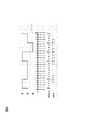
- FIG. 9 shows a sequence diagram showing a light emission pattern in the present embodiment.
- this sequence diagram also in this embodiment, only one color of RGB emits light at a time as in the various technical solutions described above. Then, sampling is performed in a frame of time indicated by a two-dot chain line in FIG. 9, and a color is detected. If the color in the frame does not change, the sampled color is also uniquely determined. However, if sampling is performed at a timing at which the color changes in the frame, the sampling value is indefinite (see the figure).
- FIG. 9 the value of the data detected by sampling is shown at the bottom.
- R * G ⁇ R * B: “0” R * B ⁇ R * G: “1”
- R * B ⁇ G * B: “0” G * B ⁇ R * G: “1”
- G * B ⁇ R * G: “0” G * B ⁇ R * G: “0”
- data is assigned to “changes in change” (switching of periodic changes in color).
- the first “change” in the change change is a periodic color change. For example, a color of R and a color of G are alternately displayed periodically as in R * G. Say that.
- the latter “change” is a change of “color change”, and specifically, a change of a combination of displayed colors.
- the latter “change” is often referred to as “switching” for easy distinction. That is, expressions such as “switching color change” and “switching periodically changing color” are adopted.
- the change includes not only the change of the color that changes periodically but also the change of timing in theory (as the scope of the right of the invention).
- RGRG and GRGR are technically recognized as different color changes.
- these may be regarded as the same color change.
- the object can be tracked by each frame or at least every other frame difference.
- the frame period is set to less than 1 ⁇ 2 of the color change period.
- the RG change period is 6 units in the figure, but the frame period is 2 units.
- the repetition of R * G and the like is repeated three times.
- the object can be detected and tracked.
- the data is expressed by “switching” of “color change”, it is not necessary to take timing in principle. In other words, it is only necessary to detect that “switching” has occurred, and the error is not affected by the timing of sampling.
- the data change is detected by detecting that the color change state is changed (change in color change). It is possible to detect without.
- the three colors of RGB always appear before and after the “change in color change”, so that the relative relationship between them can always be recognized, and RGB is correctly recognized. be able to. In other words, it is possible to perform calibration for three colors.
- the same two-color change (for example, R * G (R ⁇ G ⁇ R ⁇ G)) continues for a plurality of periods as in the example of “Technology Proposal 1”. It is also closely related to not being. That is, since it always shifts to another pattern in one period, there is a feature that three colors always appear regularly.
- the RGB values can be periodically re-recognized, so that it can be said that it is adaptable to disturbance and has high resistance to disturbance.
- one period originally means one period representing one data such as “0” or “1”, but is substantially the same as a period in which a change of two colors repeats. In practice, the same two colors are repeated for the same period, so this repeated period is called one period for convenience.
- R * G the number of repetitions in the case of alternately emitting colors is inherently free, and in particular, R ⁇ G must be an integral multiple of one cycle. Nor. Specifically, it may end with R ⁇ G ⁇ R ⁇ G ⁇ R (2.5 cycles). In short, it is only necessary to detect a change. In this case, 2.5 cycles is “one period”. However, as described below, the cycle of one period may change slightly. Now, in this way, although one period is almost the same cycle in many cases, using the property that it may be different, when the state of color change is switched, for example, the set of colors after switching It is preferred to continue the change after any color. Details will be described below.
- the color change switching of the color change state
- R is the common color. If the expression is changed, the color change after switching from R which is a common color is started.
- RBRB is started after becoming “R” once. If the expression is changed, the color change after switching starts from “R” and starts “RBRB”.
- the light emitting means can emit light in three colors of R, G, and B.
- the light emitting means can be easily realized. It is possible to increase the number of colors. It is also preferable to prepare light emitting means for each color and use each light emitting means by switching. For example, it is also a preferable aspect to arrange LEDs of three colors R, G, and B in close proximity.
- Modification 2 of Embodiment 1 The same effect can be obtained by using a change (pulsation) in the emission intensity instead of the color change.
- a signal having the same hue but different intensity is recorded for each frame, and the signal can be cut out and traced only by the difference between frames.
- FIG. 10 (a) shows a sequence diagram in which the horizontal axis represents time and the vertical axis represents emission intensity.
- FIG. 10A when R (red) color is emitted, light is emitted with different emission intensity for each frame. In the example of this figure, light is emitted with an intensity change of “2” ⁇ “3” ⁇ “4” ⁇ “1”.
- this “2” ⁇ “3” ⁇ “4” ⁇ “1” “intensity change” changes.
- the “color” of “intensity change” of “2” ⁇ “3” ⁇ “4” ⁇ “1” changes. That is, after light emission with the above intensity change is performed with R, the color is changed to G and light emission with the same intensity change is performed again. Further, FIG. 10A shows a state in which the color changes to B and light emission with the same intensity change is performed.
- the former change of the “change of change” in this example is a change in luminescence intensity (pulsation), and the latter change is a change in color.
- the intensity change is made temporally asymmetric so that the exposure amount for each frame is always different. That is, it is configured such that the intensity of any frame does not match by changing “2” ⁇ “3” ⁇ “4” ⁇ “1”.
- FIG. 10A shows an example in which the emission intensity “changes” stepwise, it is also preferable to configure the emission intensity to change continuously as shown in FIG. 10B.
- Second Embodiment Multiple Light Emitters In the first embodiment, an example in which 1-bit data is recorded for each change in color change has been described. Therefore, for example, consider switching color changes under the following conditions.
- the number of “changes” of “color change” per second is five, and thus the data discharge speed is 5 bits / sec.
- One possible means of increasing this data rate is to line up multiple light emitters. If n pieces are arranged, the data speed becomes n times in principle. However, it is necessary to distinguish the n light emitters. For example, it is necessary to clearly know in advance which illuminant represents which digit of the binary number.
- the light emission pattern is basically the same as the method shown in the first embodiment. However, the same color will not be adjacent at the same timing. By attaching this condition, data can be read even when the two light emitters cannot be distinguished.
- the light emission methods (color changes) that can be identified are as follows.
- the notation R * G and the notation G * R are common in that R and G emit light alternately, but their phases are opposite.
- each light emitter alternately emits two colors using RGB three colors.
- the light emission patterns of the first light emitter and the second light emitter the following can be recognized.
- data is represented by pattern switching (color change switching). Since there are five types of transition from one pattern to another, 0, 1, 2, 3, 4 can be represented by a single pattern change. That is, it can represent one digit of a quinary number.
- the six squares arranged side by side schematically represent the state of color change, and the horizontal direction represents the passage of time.
- RGRRGRG represents a state in which R and G emit light alternately, and represents R * G.
- GRGRGR is expressed as G * R, and the phase is also taken into consideration.
- the six grids arranged in two stages above and below indicate that there are two light emitters, and a total of 12 grids represent “color change”.
- double-line arrows indicate that “color change” is switched, and twelve squares before and after the double-line arrow indicate color change switching.
- the 12th cell in front of the double line arrow is the “color change” before switching, and the one in the direction of the double line arrow is the “color change” after switching. .
- the first light emitter and the second light emitter are not permitted to have the same color at the same timing, but an example in which the same color adjacency is permitted at the same timing (Modification 1). ).
- the case where the “color change” of the first light emitter and the second light emitter is completely the same is not allowed.
- an example in a situation where light emission with the same color may occur in a part of the light emission pattern will be described. Other conditions are the same as those in the second embodiment.
- the following patterns can be recognized.
- Pattern 1 R * G + G * R Pattern 2: R * G + B * R Pattern 3: R * G + R * B Pattern 4: R * G + G * B Pattern 5: R * G + B * G Pattern 6: G * B + R * B Pattern 7: G * B + B * R Pattern 8: G * B + B * G Pattern 9: B * R + R * B
- the change from the pattern 3 to the pattern 7 is represented as “3 ⁇ 7”, and the meaning of each cell is as described above.
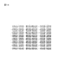
- Pattern 1 R * G + G * R + R * G Pattern 2: R * G + B * R + R * G Pattern 3: R * G + R * B + R * G Pattern 4: R * G + B * R + G * R Pattern 5: R * G + B * G + R * G Pattern 6: R * G + G * G + G * R Pattern 7: R * G + B * G + G * R Pattern 8: R * B + B * R + R * B Pattern 9: R * B + B * G + R * B Pattern 10: R * B + G * B + R * B Pattern 11: R * B + B * G + B * R Pattern 12: R * B + R * G + R * B Pattern 13: R * B + G * R + R * B Pattern 14: R * B + R * G + B * R Pattern 15: G * B + B * G + G * B Pattern 16: G * B + R * G + G * B Pattern 17: G * B + G * B Pattern 18: G * B + R * G + B * G Pattern 19:
- Interim summary 1 In accordance with the embodiments described so far, by incorporating a light emitting device including one or more light emitters into an aircraft, a ship, a vehicle, etc., data display / data by switching color changes It is possible to detect the position of the target object while performing communication, and to realize a technology that can easily recognize and track the target object.
- an object to which a light emitting device is attached is photographed with a CCD camera or the like, and a plurality of objects are traced on the photographed screen while tracking the objects. ID and various information can be received. That is, information on the object can be obtained while tracking the “position” of the object.
- a photographing camera it is also preferable to attach a photographing camera to the moving body side and attach a light emitting device to a traffic sign on the ground.
- a system that can know the meaning of the traffic sign as well as the position and direction of the traffic sign. It also contributes to the construction of a system that gives warnings to the driver based on the direction of the obtained traffic sign and its contents.
- Embodiment 3 As described so far, by using the change of color change, it is possible to track the object and read the displayed data.
- the regularity for making the light emission pattern coherent data will be considered. It is possible to display some data by the method described above. However, it is just a list of data, and in order for this list of data to make sense, it is necessary to have clear delimiters. Furthermore, in consideration of the characteristics of the present invention and the characteristics of the proposed light emission pattern, it is generally necessary to have “ID data” indicating what the light emitter (light emitting device) is. Further, in consideration of the amount of data and the data rate that can be transmitted in this method, it is possible to put (add) some “transmission information” on “ID data”, which is often meaningful in use. For example, the name of the product (vegetables) is ID, and in addition to that, the date of manufacture may be added.
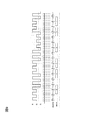
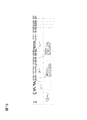
- FIG. 15 is an explanatory diagram showing the state of the code when the partition and the margin are provided and the ID and the data pattern are provided as described above.
- a pattern that repeats only R * G and G * B is used as a margin pattern.
- FIG. 15 shows an example of repeating k times (k is a positive integer), but the number of repetitions may be any number.
- a unit of alternate light emission such as R * G (between other combinations of alternate light emission) is called a module.
- this module is represented by one grid.
- Each square in FIG. 15 represents an alternate light emission pattern of two colors such as R * G and G * B.
- the upper grid in FIG. 15 represents the alternate light emission of R and G as shown on the left side.
- the middle cell represents the alternate light emission of G and B, as is also shown on the left side.
- the lower cell represents alternating light emission of B and R as shown on the left side.
- this margin pattern The unit of communication / display consisting of ID pattern and DATA pattern is called a cycle. Sending data in units of cycles and receiving data and IDs in each cycle is considered to have high compatibility with existing general communication methods and broaden the application range.
- the ID pattern and the DATA pattern do not include a portion that matches at least a repetitive pattern of R * G and G * B composed of k modules similar to the blank pattern, as a pattern generation rule.
- the ID pattern and the DATA turn can take any length, although there are such content restrictions.
- a blank pattern can always be found while following at least one cycle of light emission pattern (1 cycle), and the number of modules matches the separation module.
- the ID pattern and the DATA pattern can be confirmed respectively while confirming.
- Modification 1 of Embodiment 3 it is also preferable to specify a data sequence by adding a specification pattern in addition to an ID pattern and a DATA pattern and reading the same with the same mechanism.
- cycle Margin pattern + separator module + ID pattern + separator module + + DATA pattern + separation module + specification pattern + separation module It is also suitable.
- the specification pattern is placed last, but it is also preferable to place the specification pattern in front of the ID pattern.
- Modification 2 of Embodiment 3 data is communicated in the above one cycle.
- This one cycle is preferably repeated continuously at least twice. This is because if the light is emitted continuously for at least two cycles, the possibility of reading the data of at least one of the cycles becomes high, and the possibility of successful tracking increases.
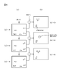
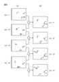
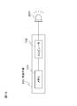
- Embodiment 4 Specific Configuration of Light-Emitting Device
- a light-emitting device including a light-emitting body that emits light in a predetermined color emission pattern has been described so far.
- Such a light-emitting device includes a light-emitting body and a control unit. It is preferred that This is shown in FIG.
- the control means 100 is preferably composed of a computer 102 and a memory 104 storing a light emission pattern.
- the memory 104 also stores a table showing a correspondence relationship between data to be represented and changes in the light emission pattern.
- the computer receives data to be displayed from the outside, the computer reads from the table a light emission pattern of a change destination for representing the data from the current light emission pattern, and causes the light emitter to emit light with the light emission pattern of the change destination.
- the light emitter 200 is preferably composed of a full color LED or the like as described above.
- the LED of three colors, R color LED, G color LED, and B color LED by sequentially switching them.
- R color LED Red, Green, Blue
- G color LED Green, Blue
- B color LED blue, Blue
- the light emitting device is preferably configured as a small portable device, but it is also preferable to use an existing notebook computer or the like.
- a notebook computer has a memory (hard disk / semiconductor memory) for storing a light emission pattern and the like, and also has a display with a backlight as a light emitter, so that the light emitting device can be configured as it is. it can.
- Embodiment 5 In the embodiments described so far, since the color changes periodically, it is extremely useful to have no so-called light emission. Thus, since there is no “break” of light emission, the possibility of losing sight of an object when tracking and tracking the object can be reduced, and a highly convenient system can be constructed.
- the period of continuous interruption (light-out period) can be suppressed to two cycles at the maximum, according to the experiments of the present inventor, the object is often used. Can be tracked and tracked efficiently.
- the sixth embodiment proposes a mode in which recognition and tracking are performed separately.
- Step 1 a change in color change is recognized to recognize an object.
- Step 2 The position of the recognized object is specified.
- Step 3 The point where the color has changed is acquired from the photographed image.
- Step 4 A point where the color (or luminance) has changed near the position of the object in Step 2 is searched.
- Step 5 The searched point is recognized as the new position of the object.
- the recognition of what the object is is performed only in the first step 1.
- tracking is performed by detecting only the movement of the object from the change in color on the image.
- recognition is performed when the object is stationary. It is also suitable to perform “tracking” when moving. As long as the robot is stationary, it is preferable to perform recognition, and when it starts to move, stop recognition and concentrate on tracking.
- Step 1 Recognize the color (or color change) and restore the data to “recognize” the contents of the object.
- Step 2 Step 2 and subsequent steps are the same as those in the sixth embodiment.
- the recognition process is performed periodically (for example, once every few seconds or once every few minutes). It is also suitable.
- provisional data Allocation of provisional data If there are multiple objects that cannot be recognized but are treated as unrecognized and tracked, it is preferable to assign provisional data and manage and identify each unrecognized object with provisional data. It is. Thereafter, when data is recognized by executing a recognition process every certain period of time, it is preferable that the data be assigned as temporary data.
- Display of data It is to recognize the light emitted from the light emitting device attached to the object and obtain the data that it represents, that is, to recognize the object, but the data of the recognized object Is preferably displayed to the user together with the position of the object.
- the position on the image data It is also preferable to display the position with numerical values of coordinates on the image data, but it is also preferable to display the position on the image with an arrow indicating the position and a frame surrounding the region. If the recognized data is displayed in the vicinity of the arrow or the frame, it is preferable that the position and the content of the object can be easily grasped at the same time.
- the light emitted from the light emitting device is detected as a region, it is also preferable to display this region with a different color, or to indicate a boundary line indicating the contour of the region. It is also preferable to display the area with a so-called zebra pattern.
Landscapes
- Physics & Mathematics (AREA)
- Electromagnetism (AREA)
- Engineering & Computer Science (AREA)
- Computer Networks & Wireless Communication (AREA)
- Signal Processing (AREA)
- General Physics & Mathematics (AREA)
- Radar, Positioning & Navigation (AREA)
- Remote Sensing (AREA)
- Optical Communication System (AREA)
- Length Measuring Devices By Optical Means (AREA)
- Image Analysis (AREA)
Priority Applications (1)
| Application Number | Priority Date | Filing Date | Title |
|---|---|---|---|
| US13/028,662 US8453934B2 (en) | 2008-08-21 | 2011-02-16 | Light emitting device and method for tracking object |
Applications Claiming Priority (2)
| Application Number | Priority Date | Filing Date | Title |
|---|---|---|---|
| JP2008212973A JP5155063B2 (ja) | 2008-08-21 | 2008-08-21 | 発光装置及び対象物の追尾方法 |
| JP2008-212973 | 2008-08-21 |
Related Child Applications (1)
| Application Number | Title | Priority Date | Filing Date |
|---|---|---|---|
| US13/028,662 Continuation-In-Part US8453934B2 (en) | 2008-08-21 | 2011-02-16 | Light emitting device and method for tracking object |
Publications (1)
| Publication Number | Publication Date |
|---|---|
| WO2010021273A1 true WO2010021273A1 (ja) | 2010-02-25 |
Family
ID=41707151
Family Applications (1)
| Application Number | Title | Priority Date | Filing Date |
|---|---|---|---|
| PCT/JP2009/064179 Ceased WO2010021273A1 (ja) | 2008-08-21 | 2009-08-11 | 発光装置及び対象物の追尾方法 |
Country Status (4)
| Country | Link |
|---|---|
| US (1) | US8453934B2 (enExample) |
| JP (1) | JP5155063B2 (enExample) |
| TW (1) | TW201031131A (enExample) |
| WO (1) | WO2010021273A1 (enExample) |
Cited By (3)
| Publication number | Priority date | Publication date | Assignee | Title |
|---|---|---|---|---|
| EP2538584A1 (en) * | 2011-06-23 | 2012-12-26 | Casio Computer Co., Ltd. | Information Transmission System, Information Sending Device, Information Receiving Device, Information Transmission Method, Information Sending Method and Information Receiving Method |
| WO2016001972A1 (ja) * | 2014-06-30 | 2016-01-07 | 富士通株式会社 | 送信装置、受信装置、通信システム、及び送信方法ならびに受信方法 |
| CN106842124A (zh) * | 2017-01-16 | 2017-06-13 | 苏州优函信息科技有限公司 | 多光谱空间定位方法及系统 |
Families Citing this family (25)
| Publication number | Priority date | Publication date | Assignee | Title |
|---|---|---|---|---|
| EP2810267A1 (de) * | 2012-02-03 | 2014-12-10 | Continental Teves AG&Co. Ohg | SIGNALGEBER, SYSTEM UND VERFAHREN ZUR HERVORHEBUNG VON OBJEKTEN IM STRAßENVERKEHR SOWIE VERWENDUNG DES SYSTEMS UND VERWENDUNG DES SIGNALGEBERS |
| JP5938960B2 (ja) * | 2012-03-15 | 2016-06-22 | カシオ計算機株式会社 | 電子機器、遠隔操作制御システム、遠隔操作制御方法及びプログラム |
| US10757369B1 (en) * | 2012-10-08 | 2020-08-25 | Supratik Mukhopadhyay | Computer implemented system and method for high performance visual tracking |
| US9087349B2 (en) | 2012-12-27 | 2015-07-21 | Panasonic Intellectual Property Corporation Of America | Information communication method |
| US10303945B2 (en) | 2012-12-27 | 2019-05-28 | Panasonic Intellectual Property Corporation Of America | Display method and display apparatus |
| CN104871454B (zh) | 2012-12-27 | 2018-09-28 | 松下电器(美国)知识产权公司 | 信息通信方法和信息通信装置 |
| US10523876B2 (en) | 2012-12-27 | 2019-12-31 | Panasonic Intellectual Property Corporation Of America | Information communication method |
| US10530486B2 (en) * | 2012-12-27 | 2020-01-07 | Panasonic Intellectual Property Corporation Of America | Transmitting method, transmitting apparatus, and program |
| US10951310B2 (en) | 2012-12-27 | 2021-03-16 | Panasonic Intellectual Property Corporation Of America | Communication method, communication device, and transmitter |
| TWI515666B (zh) * | 2013-05-03 | 2016-01-01 | 仁寶電腦工業股份有限公司 | 互動式物件追蹤系統及其互動式物件與追蹤方法 |
| CN104767566B (zh) * | 2014-01-07 | 2018-11-30 | 中兴通讯股份有限公司 | 一种缓解帧间闪烁的调光方法和装置 |
| CN104796194B (zh) * | 2014-01-16 | 2017-08-29 | 中国联合网络通信集团有限公司 | 一种基于可见光通信的自适应多点追踪方法与装置 |
| JP6011569B2 (ja) * | 2014-03-13 | 2016-10-19 | カシオ計算機株式会社 | 撮像装置、被写体追尾方法及びプログラム |
| US20160171504A1 (en) * | 2014-12-11 | 2016-06-16 | Schneider Electric Industries Sas | Blink code product registration |
| JP6183386B2 (ja) * | 2015-01-28 | 2017-08-23 | カシオ計算機株式会社 | 光通信装置、光推定装置、光通信方法、及び、プログラム |
| DE102016202505A1 (de) * | 2016-02-18 | 2017-08-24 | Osram Gmbh | Kommunikationsvorrichtung und -Verfahren für eine strahlungsbasierte Kommunikation zwischen Fahrzeugen und Fahrzeug mit der Kommunikationsvorrichtung |
| JP6693365B2 (ja) * | 2016-09-20 | 2020-05-13 | カシオ計算機株式会社 | 報知装置、報知方法及びプログラム |
| JP7134094B2 (ja) * | 2016-12-15 | 2022-09-09 | パナソニック インテレクチュアル プロパティ コーポレーション オブ アメリカ | 送信方法、送信装置、およびプログラム |
| US10542221B2 (en) | 2017-07-06 | 2020-01-21 | OSRAMS SYLVANIA Inc. | Light-based communication using camera frame-rate based light modulation |
| JP6701153B2 (ja) | 2017-11-10 | 2020-05-27 | 株式会社Subaru | 移動体の位置計測システム |
| FR3078849B1 (fr) * | 2018-03-09 | 2020-03-27 | Jcdecaux Sa | Procede et dispositif pour transmettre un message code lumineux, notamment aux fins de verifier l'affiche d'un contenu par un ecran electronique |
| TWI689743B (zh) * | 2018-06-13 | 2020-04-01 | 合盈光電科技股份有限公司 | 物件定位系統 |
| JP2021082907A (ja) * | 2019-11-18 | 2021-05-27 | 富士フイルムビジネスイノベーション株式会社 | 情報処理装置、点灯装置、プログラム、及び情報処理システム |
| JP2020115140A (ja) * | 2020-03-17 | 2020-07-30 | 株式会社Subaru | 移動体の位置計測システム |
| JP7602919B2 (ja) * | 2021-01-08 | 2024-12-19 | 日本放送協会 | マーカ及びマーカ識別装置、並びに、それらのプログラム |
Citations (5)
| Publication number | Priority date | Publication date | Assignee | Title |
|---|---|---|---|---|
| JP2001189660A (ja) * | 1999-12-28 | 2001-07-10 | Toshiba Corp | 情報伝送装置および情報伝送方法 |
| JP2004032529A (ja) * | 2002-06-27 | 2004-01-29 | Nippon Conlux Co Ltd | 情報伝達方法およびシステム |
| JP2004056343A (ja) * | 2002-07-18 | 2004-02-19 | Sony Corp | データ通信システム、データ送信装置及び方法、並びにデータ受信装置及び方法 |
| JP2005136665A (ja) * | 2003-10-30 | 2005-05-26 | Nippon Telegr & Teleph Corp <Ntt> | データ信号の送信方法と受信方法及びその装置、システム、プログラム並びに記録媒体 |
| WO2006109829A1 (ja) * | 2005-04-12 | 2006-10-19 | Pioneer Corporation | 通信システム、通信装置及び方法、並びにコンピュータプログラム |
Family Cites Families (8)
| Publication number | Priority date | Publication date | Assignee | Title |
|---|---|---|---|---|
| JP4135238B2 (ja) * | 1998-12-08 | 2008-08-20 | 日立オムロンターミナルソリューションズ株式会社 | 紙幣入出金機 |
| US6601045B1 (en) * | 1998-12-29 | 2003-07-29 | Diebold, Incorporated | Secure depository system |
| GB9907515D0 (en) * | 1999-04-01 | 1999-05-26 | Ncr Int Inc | Self service terminal |
| JP3374175B2 (ja) | 2000-01-27 | 2003-02-04 | 名古屋大学長 | 位置表示用データ送信機能付きデータ送信装置、(以下[発明の名称の続き]欄に記載) |
| JP2003179556A (ja) * | 2001-09-21 | 2003-06-27 | Casio Comput Co Ltd | 情報伝送方式、情報伝送システム、撮像装置、および、情報伝送方法 |
| MXPA05006714A (es) * | 2002-12-19 | 2005-11-23 | Diebold Inc | Maquina bancaria automatizada surtidora de efectivo con dispositivos de iluminacion de interconexion de usuario. |
| JP2004226227A (ja) | 2003-01-23 | 2004-08-12 | Shigeo Kaneda | 位置検出システム |
| JP4005621B1 (ja) | 2006-07-19 | 2007-11-07 | ビーコア株式会社 | 光学式シンボル及びそれが付された物品並びに光学式シンボルを物品に付す方法及び光学式シンボルのデコード方法。 |
-
2008
- 2008-08-21 JP JP2008212973A patent/JP5155063B2/ja active Active
-
2009
- 2009-08-11 WO PCT/JP2009/064179 patent/WO2010021273A1/ja not_active Ceased
- 2009-08-20 TW TW098128049A patent/TW201031131A/zh unknown
-
2011
- 2011-02-16 US US13/028,662 patent/US8453934B2/en not_active Expired - Fee Related
Patent Citations (5)
| Publication number | Priority date | Publication date | Assignee | Title |
|---|---|---|---|---|
| JP2001189660A (ja) * | 1999-12-28 | 2001-07-10 | Toshiba Corp | 情報伝送装置および情報伝送方法 |
| JP2004032529A (ja) * | 2002-06-27 | 2004-01-29 | Nippon Conlux Co Ltd | 情報伝達方法およびシステム |
| JP2004056343A (ja) * | 2002-07-18 | 2004-02-19 | Sony Corp | データ通信システム、データ送信装置及び方法、並びにデータ受信装置及び方法 |
| JP2005136665A (ja) * | 2003-10-30 | 2005-05-26 | Nippon Telegr & Teleph Corp <Ntt> | データ信号の送信方法と受信方法及びその装置、システム、プログラム並びに記録媒体 |
| WO2006109829A1 (ja) * | 2005-04-12 | 2006-10-19 | Pioneer Corporation | 通信システム、通信装置及び方法、並びにコンピュータプログラム |
Cited By (9)
| Publication number | Priority date | Publication date | Assignee | Title |
|---|---|---|---|---|
| EP2538584A1 (en) * | 2011-06-23 | 2012-12-26 | Casio Computer Co., Ltd. | Information Transmission System, Information Sending Device, Information Receiving Device, Information Transmission Method, Information Sending Method and Information Receiving Method |
| US8886054B2 (en) | 2011-06-23 | 2014-11-11 | Casio Computer Co., Ltd. | Information transmission system, information sending device, information receiving device, information transmission method, information sending method, information receiving method and program product |
| US9716554B2 (en) | 2011-06-23 | 2017-07-25 | Casio Computer Co., Ltd. | Information transmission system, information sending device, information receiving device, information transmission method, information sending method, information receiving method and program product |
| WO2016001972A1 (ja) * | 2014-06-30 | 2016-01-07 | 富士通株式会社 | 送信装置、受信装置、通信システム、及び送信方法ならびに受信方法 |
| CN106464365A (zh) * | 2014-06-30 | 2017-02-22 | 富士通株式会社 | 发送装置、接收装置、通信系统以及发送方法和接收方法 |
| JPWO2016001972A1 (ja) * | 2014-06-30 | 2017-04-27 | 富士通株式会社 | 送信装置、受信装置、通信システム、及び送信方法ならびに受信方法 |
| CN106464365B (zh) * | 2014-06-30 | 2019-01-11 | 富士通株式会社 | 发送装置、接收装置、通信系统以及发送方法和接收方法 |
| US10236979B2 (en) | 2014-06-30 | 2019-03-19 | Fujitsu Limited | Transmitter, receiver, communication system, and transmission and reception methods |
| CN106842124A (zh) * | 2017-01-16 | 2017-06-13 | 苏州优函信息科技有限公司 | 多光谱空间定位方法及系统 |
Also Published As
| Publication number | Publication date |
|---|---|
| US20110150285A1 (en) | 2011-06-23 |
| TW201031131A (en) | 2010-08-16 |
| JP5155063B2 (ja) | 2013-02-27 |
| US8453934B2 (en) | 2013-06-04 |
| JP2010050720A (ja) | 2010-03-04 |
Similar Documents
| Publication | Publication Date | Title |
|---|---|---|
| JP5155063B2 (ja) | 発光装置及び対象物の追尾方法 | |
| Liu et al. | Positioning beacon system using digital camera and LEDs | |
| KR101379604B1 (ko) | 정보 전송 시스템, 정보 송신 장치, 정보 수신 장치, 정보 전송 방법, 정보 송신 방법, 정보 수신 방법 및 그 프로그램을 기록한 기록 매체 | |
| JP6800858B2 (ja) | 光学的に符号化された情報を提供するためのシステムと方法 | |
| Pang et al. | LED location beacon system based on processing of digital images | |
| EP1439649A1 (en) | Data communication system, data transmitter and data receiver | |
| CN103188016A (zh) | 信息提供系统、服务器、终端装置、信息提供方法、显示控制方法 | |
| US20180309514A1 (en) | Method, apparatus and system for visible light communication | |
| CN103218596A (zh) | 具有动态多角度照明系统的条码扫描器及其条码扫描方法 | |
| US20100301120A1 (en) | Method for denoting optical recognition data with multicolor light emitters, method for marking the same, light-emitting device, and method for detecting data and position | |
| JP2013009074A (ja) | 情報伝送システム、受光装置、情報伝送方法、及び、プログラム | |
| WO2015045416A1 (ja) | 表示方法および表示装置 | |
| US20180083702A1 (en) | Optical communication device, optical communication method, and non-transitory recording medium | |
| JP5366026B2 (ja) | 情報伝送システム、情報送信装置、情報受信装置、情報伝送方法、情報送信方法、情報受信方法、及び、プログラム | |
| KR20190032837A (ko) | 광 카메라 통신 시스템에서 관심 영역을 설정하는 방법 및 이를 위한 장치 | |
| JP2019029695A (ja) | 判別用コンピュータプログラム、判別装置及び判別方法ならびに通信システム | |
| US20080219676A1 (en) | Transmitting device, receiving device, and optical communication method | |
| JP4322145B2 (ja) | 光学タグシステム | |
| GB2380883A (en) | Location and identification of participants in a sporting event by means of optically readable tags | |
| JP4952977B2 (ja) | 情報伝送システム、撮像装置、及び、経路案内プログラム | |
| JP4665585B2 (ja) | 光送信機、光受信機及び光通信システム | |
| JP6141567B1 (ja) | 可視像単位識別コード構造 | |
| JP6508730B2 (ja) | 発光マーカ装置、マーカ検出装置、伝送システム、マーカ発光方法、マーカ検出方法、及びプログラム | |
| JP2023129837A (ja) | 画像表示プログラム、画像表示装置、画像表示システム及び画像表示方法 | |
| CN108810440A (zh) | 视频数字水印隐写的实现方法及系统 |
Legal Events
| Date | Code | Title | Description |
|---|---|---|---|
| 121 | Ep: the epo has been informed by wipo that ep was designated in this application |
Ref document number: 09808209 Country of ref document: EP Kind code of ref document: A1 |
|
| NENP | Non-entry into the national phase |
Ref country code: DE |
|
| 122 | Ep: pct application non-entry in european phase |
Ref document number: 09808209 Country of ref document: EP Kind code of ref document: A1 |