WO2010021148A1 - 形状・傾斜検知及び/又は計測光学装置及び方法並びにその関連装置 - Google Patents
形状・傾斜検知及び/又は計測光学装置及び方法並びにその関連装置 Download PDFInfo
- Publication number
- WO2010021148A1 WO2010021148A1 PCT/JP2009/003995 JP2009003995W WO2010021148A1 WO 2010021148 A1 WO2010021148 A1 WO 2010021148A1 JP 2009003995 W JP2009003995 W JP 2009003995W WO 2010021148 A1 WO2010021148 A1 WO 2010021148A1
- Authority
- WO
- WIPO (PCT)
- Prior art keywords
- polarization
- light
- shape
- angle
- incident
- Prior art date
- Legal status (The legal status is an assumption and is not a legal conclusion. Google has not performed a legal analysis and makes no representation as to the accuracy of the status listed.)
- Ceased
Links
Images














Classifications
-
- A—HUMAN NECESSITIES
- A61—MEDICAL OR VETERINARY SCIENCE; HYGIENE
- A61B—DIAGNOSIS; SURGERY; IDENTIFICATION
- A61B5/00—Measuring for diagnostic purposes; Identification of persons
- A61B5/103—Measuring devices for testing the shape, pattern, colour, size or movement of the body or parts thereof, for diagnostic purposes
- A61B5/107—Measuring physical dimensions, e.g. size of the entire body or parts thereof
- A61B5/1077—Measuring of profiles
-
- A—HUMAN NECESSITIES
- A61—MEDICAL OR VETERINARY SCIENCE; HYGIENE
- A61B—DIAGNOSIS; SURGERY; IDENTIFICATION
- A61B5/00—Measuring for diagnostic purposes; Identification of persons
- A61B5/0059—Measuring for diagnostic purposes; Identification of persons using light, e.g. diagnosis by transillumination, diascopy, fluorescence
- A61B5/0062—Arrangements for scanning
- A61B5/0064—Body surface scanning
-
- A—HUMAN NECESSITIES
- A61—MEDICAL OR VETERINARY SCIENCE; HYGIENE
- A61B—DIAGNOSIS; SURGERY; IDENTIFICATION
- A61B5/00—Measuring for diagnostic purposes; Identification of persons
- A61B5/0059—Measuring for diagnostic purposes; Identification of persons using light, e.g. diagnosis by transillumination, diascopy, fluorescence
- A61B5/0082—Measuring for diagnostic purposes; Identification of persons using light, e.g. diagnosis by transillumination, diascopy, fluorescence adapted for particular medical purposes
- A61B5/0091—Measuring for diagnostic purposes; Identification of persons using light, e.g. diagnosis by transillumination, diascopy, fluorescence adapted for particular medical purposes for mammography
-
- A—HUMAN NECESSITIES
- A61—MEDICAL OR VETERINARY SCIENCE; HYGIENE
- A61B—DIAGNOSIS; SURGERY; IDENTIFICATION
- A61B5/00—Measuring for diagnostic purposes; Identification of persons
- A61B5/43—Detecting, measuring or recording for evaluating the reproductive systems
- A61B5/4306—Detecting, measuring or recording for evaluating the reproductive systems for evaluating the female reproductive systems, e.g. gynaecological evaluations
- A61B5/4312—Breast evaluation or disorder diagnosis
-
- G—PHYSICS
- G01—MEASURING; TESTING
- G01B—MEASURING LENGTH, THICKNESS OR SIMILAR LINEAR DIMENSIONS; MEASURING ANGLES; MEASURING AREAS; MEASURING IRREGULARITIES OF SURFACES OR CONTOURS
- G01B11/00—Measuring arrangements characterised by the use of optical techniques
- G01B11/24—Measuring arrangements characterised by the use of optical techniques for measuring contours or curvatures
-
- G—PHYSICS
- G02—OPTICS
- G02B—OPTICAL ELEMENTS, SYSTEMS OR APPARATUS
- G02B21/00—Microscopes
- G02B21/0004—Microscopes specially adapted for specific applications
- G02B21/0092—Polarisation microscopes
-
- G—PHYSICS
- G02—OPTICS
- G02B—OPTICAL ELEMENTS, SYSTEMS OR APPARATUS
- G02B27/00—Optical systems or apparatus not provided for by any of the groups G02B1/00 - G02B26/00, G02B30/00
- G02B27/28—Optical systems or apparatus not provided for by any of the groups G02B1/00 - G02B26/00, G02B30/00 for polarising
Definitions
- the present invention relates to a shape / tilt detection and / or measurement optical device and an object information extraction method.
- the present invention relates to a shape measurement / inclination detection and / or measurement optical device and object information extraction method suitable for a shape measurement microscope, a biomicroscope, a shape measurement telescope, a medical diagnostic device, a mammography device, a tilt sensor, and the like.
- the present invention also relates to a circularly polarized illumination device and method, and particularly suitable for a shape measurement camera, a biomicroscope, a shape measurement telescope, an inner surface shape measurement device such as a cylinder, an aspherical shape measurement device, a mammography device, and a tilt sensor.
- the present invention relates to a circularly polarized illumination apparatus for a sample.
- a three-dimensional sample is illuminated with appropriate illumination light, and an image is enlarged and projected by a microscopic optical system.
- the projection surface is a two-dimensional surface such as a CCD detector, and information on the shape of the sample in the thickness direction is generally lost.
- a confocal microscope has been put to practical use as a microscope for reconstructing a 3D image by obtaining a plurality of 2D images of a cross section in the thickness direction by this device that can enhance the 2D property [ Edited by Kuniaki Takada, “Protocol Microscope Utilization Protocol for the First Time”, Yodosha, published in December 2003, ISBN: 9784897064130 (Non-patent Document 1), International Publication No. WO2004 / 036284 (Patent Document 1)].
- it is indispensable to sequentially capture two-dimensional images at a plurality of sample depths in time series, and it is assumed that there is no deformation of the sample within the observation time.
- the device has been devised to achieve high speed by scanning the intensity distribution of a two-dimensional image at high speed and detecting it synchronously with an array detector with a special configuration.
- the imaging conditions and the environment are complicated, it takes a lot of cost to obtain a stable operation.
- Non-patent Document 3 Japanese Patent Publication No. 61-17281, “Glossy surface direction detection method” (Patent Document 2)].
- the measurement method is a polarimetric measurement that handles partially polarized light.In principle, measurement sensitivity can be obtained with a transparent material, but sensitivity cannot be obtained with a metal surface. It is focused on simple measurements. In these methods, although the shape reproduction is realized in the transparent body, the accuracy of the measurement angle is about several degrees. In addition, since the reflection of the p-polarized component does not become zero at the polarization angle and the metal sample simply takes a local minimum value, the difference in reflection intensity is small and cannot be applied in principle.
- Polarization is light in which an electric field and a magnetic field are oscillating with a bias in a specific direction.
- the polarization is generally elliptical polarization, but there are also linear polarization and circular polarization.
- light is an electromagnetic wave, and the electromagnetic field is a transverse wave that vibrates perpendicular to the traveling direction.
- the vibration direction of the electric field (and magnetic field) is constant, and the vibration plane of the linearly polarized light indicates the direction of the electric field.
- Circularly polarized light draws a circle as the vibration of the electric field (and magnetic field) propagates, and includes right-handed circularly polarized light and left-handed circularly-polarized light depending on the rotation direction.
- the elliptically polarized light is the most common polarization state expressed by linear combination of linearly polarized light and circularly polarized light, and the vibration of the electric field (and magnetic field) draws an ellipse with respect to time.
- Elliptical polarized light also includes right elliptical polarized light and left elliptical polarized light.
- Ellipsometry is a polarization measurement method that provides high measurement accuracy compared to polarimetry. In polarimetry, partially polarized light including a non-polarized component accompanying light scattering or the like is measured. On the other hand, in ellipsometry, in order to handle reflection on a surface smooth enough not to cause scattering, the measurement accuracy is high because the shape of a polarization ellipse indicating the polarization state of completely polarized light is used as a measurement object.
- Non-Patent Document 5 Regarding the measurement and analysis method of polarization, Masaki Yamamoto, “Polarization measurement and polarization analysis method”, Teruji Kose et al., “Optical engineering handbook”, Asakura Shoten, 1986, pp. 411-427 (non-patent document 4) and You can refer to Yuichi Ozawa and Shunichi Sato, “Axisymmetric Polarized Beam”, Optics, Vol. 35, No. 12 (2006), pp. 9-18 (Non-Patent Document 5).
- Patent Document 6 Japanese Patent Application Laid-Open No. 11-211433].
- the measurement principle of these shape recognition applications is polarimetry, for example, a tilt that utilizes the fact that the tilt angle dependence of the degree of polarization, which indicates the “bias” of the scattering of the snow surface, approaches the maximum value of 1 in the polarization angle of water. It is a measurement method. Although the measurement accuracy of the degree of polarization is only a few percent, the application to shape recognition is currently limited, but by using polarized light, it is possible to directly read the “tilt” and reconstruct the object shape in real time. ing.
- Patent Document 3 Japanese Patent Publication No. Sho 61-17281.
- Non-patent Document 7 development of a polarization camera [Non-Patent Document 7] is also progressing, and application of extraction of various object shapes is also progressing.
- ellipsometry is known as a precision measurement method using polarized light.
- linearly polarized light is used as a probe and obliquely incident on a planar sample, and the optical properties of the sample and the thickness of the thin film are precisely measured from changes in the polarization state of reflection.
- the main incident angle method [Non-Patent Document 4] is known, which utilizes the incident angle dependence of polarization reflection characteristics for precise measurement, but it has a standard purpose of measuring the optical characteristics of a sample. This is a technique, and the object to be measured is limited to a flat sample.
- Patent Document 4 Japanese Patent Publication No. 52-46825
- Patent Document 5 Japanese Patent Publication No. 60-41732
- Patent Document 6 Japanese Patent Publication No. 2-16458
- a conventional method such as interferometry for measuring the three-dimensional shape of an object is a geometric triangulation method in which a change in optical path length, that is, a change in distance is accurately measured. For example, in order to calculate the tilt, the calculation with the observed value at a position separated by a predetermined distance L on the observation object is performed, so that the determination error of L is also an inclination error. Further, the observed optical path length is susceptible to disturbance during the propagation of light.
- An object of the present invention is to provide a shape / tilt detection and / or measurement optical device, an optical shape / tilt detection, and a simple configuration that is resistant to disturbance and can accurately detect and / or measure the tilt angle of the surface of an object including a human body. To provide a measurement method.
- Another object of the present invention is to provide a circularly polarized illumination device and a circularly polarized illumination method that can ensure measurement accuracy by using an inclination / shape measurement method for measuring the shape of the object.
- Step 1 is to measure the polarization ellipse of the reflected light and know the azimuth of the incident surface from the measured azimuth angle of the polarization ellipse.
- the slope of the tangential plane that is, the tangential plane that reflects the incident light on the surface of the sample material is theoretically calculated. It is possible to determine the surface of the observation material Since it can be assumed to be continuous in the observation field of view, the present inventors have succeeded in finding that a three-dimensional shape can be reproduced by smoothly connecting the determined slopes of the vicinal surfaces, thereby completing the present invention.
- a shape / tilt detection and / or measurement optical device that detects and / or measures the surface shape and inclination of an observation object using the reflection optical characteristics of the surface of the object, substantially surrounds the periphery of the object And a polarization ellipse of a polarization component including a complete polarization component of a group of light rays that are specularly reflected by the object surface and emitted at a specific azimuth angle.
- a polarization image detection device for detecting the incident light, and for each reflected light beam reflected from the reflected surface of the object, the step 1 for determining the azimuth of the incident surface from the observation azimuth value of the polarization ellipse;
- a shape / tilt detection and / or measurement optical apparatus characterized in that the tilt angle of the reflecting surface with respect to the outgoing light beam is measured in step 2 in which the incident angle is determined from the ellipticity value of the polarization ellipse including the theoretical value of the ellipticity.
- Step 1 of knowing the orientation of the incident surface from the observation azimuth value of the polarization ellipse (1) Knowing the orientation of the incidence surface from the observation azimuth value of the polarization ellipse including the theoretical observation azimuth of the polarization ellipse Or (2) switching between right circular polarization and left circular polarization in an illumination device that uniformly enters light in a polarization state that surrounds the periphery of the object and that includes a substantially known complete polarization state.
- the incident plane is obtained by using the fact that the observed azimuth angle value of the reflected polarization ellipse including the theoretical observation azimuth angle value of the reflected polarization ellipse is switched symmetrically to the incident plane regardless of the reflection optical characteristics of the surface of the object.
- An illumination device that uniformly enters light in a polarization state that includes a substantially known complete polarization state surrounding the periphery of the object, and includes a spatially specified incident ray as a measurement reference origin,
- the optical property of the reflecting surface can be specified from the observation value of the polarization ellipse at the reflection point specified by the polarization image detection device, as described in any one of [1] to [3] above Shape / tilt detection and / or measurement optics.
- a mechanism capable of extracting a azimuth angle range of light beams having substantially the same polarization ellipse by a polarization image detection device that detects a polarization ellipse of the light beams reflected on the object surface and emitted at a specific azimuth angle The shape / tilt detection and / or measurement optical apparatus according to any one of [1] to [4] above, comprising:
- a polarization image detection device for detecting a polarization ellipse of a group of light beams reflected on the object surface and emitted at a specific azimuth angle spatially divides the reflected light into at least three or more and different specifications
- the shape / tilt according to any one of [1] to [5] above, wherein a plurality of analyzers capable of detecting a polarization ellipse are assigned and the polarization ellipses are simultaneously detected in parallel Detection and / or measurement optics.
- a polarization image detection apparatus that detects a polarization ellipse of a light beam reflected on the object surface and emitted at a specific azimuth angle, and has a mechanism for specifying a light beam position on the object surface by obtaining a reduced projection image of the object.
- the shape / tilt detection and / or measurement optical apparatus according to any one of the above [1] to [7], wherein [9] A polarization image detection apparatus that detects a polarization ellipse of a light beam reflected on the object surface and emitted at a specific azimuth angle, and has a mechanism for specifying a light beam position on the object surface by obtaining an enlarged projection image of the object.
- a polarization image detecting device that detects a polarization ellipse of a group of light beams reflected on the object surface and emitted at a specific azimuth has a mechanism for specifying a light beam position on the object surface by including a collimator.
- the shape / tilt detection and / or measurement optical apparatus according to any one of [1] to [7] above, wherein [11] A polarization image detection apparatus that detects a polarization ellipse of a group of light beams reflected by the object surface and emitted at a specific azimuth angle, and disposing the apparatus at a substantially infinite distance, thereby locating the light beam position on the object surface.
- the shape / tilt detection and / or measurement optical device according to any one of [1] to [7] above, which has a specifying mechanism.
- a polarization image detection device that detects a polarization ellipse of a group of light beams reflected on the object surface and emitted at a specific azimuth has a mechanism for specifying a light beam position on the object surface by providing a pinhole.
- the shape / tilt detection and / or measurement optical apparatus according to any one of [1] to [7] above, wherein [13] Includes mammography that detects and identifies specific changes in the surface tilt angle caused by various lesions including malignant tumors, using a part of the human body including the human body or breast as a detection and / or measurement object
- the shape / tilt detection and / or measurement optical device according to any one of [1] to [12] above, which is a medical diagnostic device.
- An optical shape / tilt detection and / or measurement method for detecting and / or measuring the surface shape and inclination of an observation object using reflection optical characteristics of the surface of the object, and the surroundings of the object by an illumination device Polarized light that includes a completely polarized component of a group of rays that are uniformly reflected by the surface of the object and emitted at a specific azimuth angle by allowing light of a polarization state that substantially includes a known complete polarization state to be uniformly incident.
- the polarization ellipse of the component is detected by a polarization image detection device, and the NA of the optical system of the detection device is set to the maximum value or as a function value with respect to the measurement accuracy of the polarization state.
- the orientation of the reflecting surface is obtained by knowing the orientation of the incident surface from the observation azimuth value of the polarization ellipse and the incidence angle from the ellipticity value of the polarization ellipse including the theoretical ellipticity of the polarization ellipse.
- Tilt with respect to the exit beam An optical shape / tilt detection and / or measurement method characterized in that an object is extracted by measuring an angle and utilizing the fact that the measured inclination angle changes smoothly on the surface of the object.
- [17] It is characterized in that a specific part of the surface inclination angle caused by various lesions including a malignant tumor is detected and specified by detecting and / or measuring a part of the human body including the human body or breast.
- [18] The above [16] or [16], wherein a predetermined deformation is given by a process including a change in posture of an observation object including a patient, and a change in inclination angle before and after the deformation is detected and / or measured.
- a shape / tilt detection and / or measurement optical device that detects and / or measures the surface shape and inclination of an observation object using the reflection optical characteristics of the surface of the object, substantially surrounds the periphery of the object
- An illumination device that uniformly injects light in a polarization state including a complete polarization state, and a polarization ellipse of a polarization component that includes a complete polarization component of a group of rays reflected from the object surface and emitted at a specific azimuth angle.
- a polarization image detection device for detecting, for each reflected and emitted light beam, with respect to the reflecting surface of the object that forms the incident point, that is, a vicinal surface, from the azimuth angle of the polarization ellipse to the azimuth angle of the incident surface, that is, the tangential plane
- the azimuth angle of the normal line and the reflection angle from the ellipticity of the polarization ellipse that is, the incident angle
- the angle of inclination of the reflecting surface with respect to the outgoing ray is measured, and the vicinal surface forming the tangential plane is smoothed.
- Connect to Shape and inclination sensing and / or measurement method characterized by forming the integral operation that.
- the ellipsometry measurement accuracy ⁇ 1% could be realized in the precise shape measurement by 3D tilt ellipsometry proposed by the inventor. This accuracy greatly improves at most several percent of prior art polarization measurements.
- the inventor has found that precision shape measurement by 3D tilt ellipsometry can be applied to shape / tilt measurement of the surface of an object including the inner surface, to which conventional optical shape measurement cannot be applied.
- precision optical measurement can be applied to an object to which an optical method such as an inner surface of a cylindrical object and further an inner surface of a cylindrical object sealed at one end cannot be applied.
- the precise shape / tilt measurement by 3D tilt ellipsometry proposed by the inventor the incompleteness of circularly polarized illumination light that causes measurement errors is eliminated, and the expected measurement accuracy of ellipsometry is 1% to 0.1%. Is realized. It also enables optical precision measurement of the inclination and shape of the object surface including the inner surface.
- a circularly polarized illuminating device used in an inclination / shape measurement method for measuring the shape and inclination of an object in which circularly polarized light is incident on an inclined surface constituting the object surface, including the inner surface, in a prescribed observation direction
- the circularly polarized illuminating device includes a light source device.
- the light source device has a polyhedral illumination section of a circular or rectangular shape or a combination of a plane or a curved surface directly facing the object, or a concave surface surrounding the outer surface of the object, or
- a group of circularly polarized light beams which are composed of convex surfaces directed toward the inner surface of the object, can radiate circularly polarized light including substantially perfect circularly polarized light toward the object through the section, and are incident on the object surface, according to the law of reflection.
- Regular reflection in the observation direction Circularly polarized light illumination device, characterized in that the light source device allowed to to include all of the incident light component that.
- a light source device having the illumination section includes a light source, an optical element that guides light to the section, and a circular polarizer in this order, and circularly polarized light including perfect circularly polarized light with a predetermined degree of polarization from the section.
- the circularly polarized illumination device as described in [25] above, which has a function capable of being emitted as a bundle of incident angles of light in a predetermined angle range.
- the circularly polarized illumination device according to [25] or [26], wherein the light source device having the illumination section can illuminate the object with a group of circularly polarized light beams having a degree of polarization of 99% or more. .
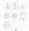
- the illumination section of the light source device is a regular polygon inscribed in a circle or a polyhedral section composed of a combination thereof.
- the circularly polarized light illumination device according to 1.
- the light source device having the illumination section includes at least a substantial surface light source in which point light sources are arranged and / or a surface light source and a circular polarizer in this order.
- the circularly polarized illumination device according to any one of 25] to [29].
- the light source device includes a light source mechanism that generates a light beam that diverges from at least one point and a spheroid reflector, and the position of the divergence point and the object is aligned with the focal point of the spheroid reflector.
- the circularly polarized illuminating device according to any one of [25] to [30], wherein the illumination light beam is converged on the object by reflection so as to enter the illumination section vertically.
- the light source device includes a light source mechanism that generates at least a parallel illumination light beam and a rotating paraboloidal mirror, the object position is arranged to coincide with the focal point of the rotating paraboloidal mirror, and the illumination light beam is reflected by reflection.
- the circularly polarized light illumination device according to any one of [25] to [30], wherein the light beam is vertically incident on the illumination section by converging the light beam on the object.
- the circularly polarized illumination device according to any one of [25] to [32], wherein an illumination angle origin reference is provided in an illumination section of the light source device.
- the circularly polarized light is incident on the inclined surface constituting the object surface including the inner surface, and the three-dimensional inclination angle of the inclined surface and the inclination are determined using the polarization characteristics of the reflected light that is regularly reflected in the specified observation direction.
- a circularly polarized illumination method used for an inclination / shape measurement method for measuring the shape and inclination of an object forming a plane is a polyhedral shape of a circle or a rectangle consisting of a plane or a curved surface directly facing the object to be measured, or a combination thereof
- a light source device comprising a plurality of illumination sections and a concave surface surrounding the outer surface of the object or a convex surface directed toward the inner surface of the object, and substantially substantially circularly polarized light toward the object through the section
- a circularly polarized illumination characterized in that a group of circularly polarized light rays that are incident on the surface of the object by irradiation with circularly polarized light including all the incident light components that can be regularly reflected in the observation direction in accordance with the law of reflection Technique.
- a two-dimensional polarized image of an object recorded by an imaging apparatus such as a microscope, a telescope, or a projection apparatus is analyzed, and an inclination angle (0 ° to 90 °) of a surface constituting the object is set to 0.01. Detect and / or measure with an accuracy of ° to 0.001 °.
- the apparatus for this purpose is a simple three-dimensional shape / tilt detection and / or measurement apparatus without requiring a complicated mechanism.
- the tilt angle of the reflecting surface is directly observed by the reflection of polarized light.
- the change in the polarization state due to reflection is a phenomenon that occurs only once in the measurement unit. Except for this reflection phenomenon, the polarization state does not change during the propagation of light.
- Both the incident polarized light and the reflected outgoing polarized light pass through a uniform medium such as air or liquid, so that the polarization state of light does not change during propagation. Therefore, the greatest feature is that the observation environment is not selected and the observation distance is not affected.
- the inclination of the object can be read directly. Since local changes in tilt can be observed precisely and in a non-contact manner, various applications are possible with simple image processing.
- a new detection and / or measurement device in various environments can be provided, and it can be widely applied.
- a three-dimensional shape / tilt measurement that can accurately measure the three-dimensional tilt and shape of the surface including the inner surface of the sample by analyzing the two-dimensional polarized image of the sample recorded by a polarization camera or the like.
- a circularly polarized illumination device that can be optimally used in the device is obtained.
- the light ray (thick line) incident on the spherical sample is reflected at each reflection point and reflected in the observation direction.
- the observation direction is the z-axis direction, and in the case of reflection on the xy plane, the reflected light is drawn parallel to the z-axis by the law of reflection.
- the sample is assumed to be transparent.
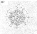
- a polarization state of light at an observation point (a circle) of a spherical sample and an observation point inside the circle that is the observation surface is schematically shown.
- the state of polarization is indicated by an ellipse in the figure, but the principal axis direction of the ellipse is orthogonal to the incident surface.
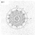
- FIG. 3 schematically shows the observation surface of a spherical sample corresponding to FIG.
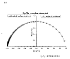
- the calculation result of the relationship between the incident angle and the complex amplitude reflectance ratio Rp / Rs when the sample is an absorber is shown. Assuming that the sample has an oxidized aluminum surface, it is shown in a complex plane display at a wavelength of 405 nm (blue light emitting diode wavelength). Since there is absorption, the complex refractive index is 0.6-5.04i. This applies when the sample is metal or the like.
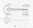
- the structure of the shape measurement telescope which is one of the shape measurement optical apparatuses of this invention is shown.
- the device is shown in the simplest basic configuration.
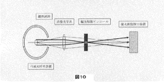
- the structure of the shape measurement microscope which is one of the shape measurement optical apparatuses of this invention is shown.
- the device is shown in one of the simplest basic configurations.
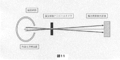
- 1 shows one configuration of a shape measuring optical device of the present invention.
- the device is shown in one of the simplest basic configurations.
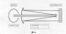
- One structural example of the shape measurement optical apparatus of this invention is shown.
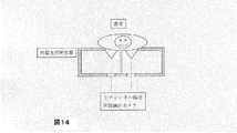
- Another structural example of the shape measuring optical device of the present invention is shown. 1 shows an example of the configuration of a mammography that is one of the shape measuring optical devices of the present invention.
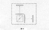
- FIG. 1 shows one configuration of an orthogonal unit used in the present invention.
- 1 schematically shows one configuration example of a shape measuring optical device of the present invention.
- Another structural example of the shape measuring optical device of the present invention is schematically shown. It is a figure explaining the case where the concept of ellipsometry prescribed
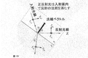
- a normal vector is determined if the azimuth angle and the incident angle of the incident surface can be determined for a light ray that is equal to the angle formed with the axis and proceeds in an arbitrary z direction.
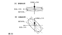
- the ellipse of the reflected polarized light observed from the z direction under circularly polarized illumination is shown.
- (a) shows the case of reflection by a dielectric sample
- (b) shows the case of reflection by a metal sample.
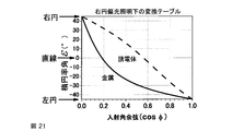
- the conversion table of observation ellipticity angle and incident angle cosine at right circularly polarized light incidence is shown.
- the circularly polarized light is incident on the inclined surface constituting the object surface, and the three-dimensional inclination angle of the inclined surface and the shape of the object forming the inclined surface are obtained by using the polarization characteristics of the reflected light that is regularly reflected in the prescribed observation direction.
- the apparatus used for the experiment of the inclination and shape measurement method to measure the angle is shown.
- the results of observation of the truncated pyramid and hemisphere using the apparatus of FIG. 19 are shown side by side on the left side and the right side. From the top, a) the observed ellipticity angle, b) the observed azimuth angle, and c) the sample photograph.
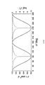
- the intensity change of the transmitted light is shown by a solid line when the polarizer and the analyzer are arranged on a straight line, the transmission axis of the polarizer is fixed at an azimuth angle of 0 °, and the direction of the transmission axis of the analyzer is ⁇ . .
- the change in intensity indicated by a logarithm according to the scale on the right vertical axis is represented by a broken line.
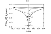
- the Malus law with polarizers of various extinction rates is shown by the azimuth change near the extinction position of the observation intensity I.
- the phase angle of the phaser using birefringence shows the incident angle dependency in principle. In such a case, however, the manner in which the allowable angle range is limited depending on the required accuracy will be described.
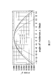
- An example in which the relationship between the phase angle of the phase shifter and the incident angle is calculated for average refractive indexes of 1.5, 1.4, and 1.0 is shown.
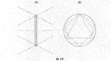
- the incident angle or the output angle of the light beam with respect to the polarizing element be within a predetermined allowable angle range, and a regular polygon inscribed in the circle indicating the allowable angle If it is an element, it indicates that it is satisfactory.
- An example of the illumination division comprised compactly by sticking a circular polarizer to a surface emitting light source is shown.
- An example in the case where an illumination section having an illumination angle origin reference is configured in the illumination section of the light source device will be described.
- a configuration example of an illumination area in which a regular polygon facing the measurement target object is an illumination section is shown.
- the light source device an example of a configuration in which a fiber light source is combined with a configuration of an illumination region in which a regular octahedron facing a measurement target object is an illumination section is shown.
- One of the specific examples of the circularly polarized illumination apparatus of this invention is shown.
- Another specific example of the circularly polarized illumination device of the present invention is shown.
- One of the specific examples in the case of the inner surface shape observation according to the present invention is shown.
- One of the other specific examples in the case of the inner surface shape observation according to the present invention will be described.
- One of the specific examples according to the present invention in the case of observation of the shape of the inner surface sealed at one end is shown.
- One of the other specific examples according to the present invention in the case of observation of the shape of the inner surface sealed at one end will be described.
- One example of another specific example according to the present invention in the case of the inner surface shape observation will be shown by taking the inner surface shape of the sample forming the paraboloid as an example.
- One of the other specific examples according to the present invention in the case of observing the inner surface shape will be described by taking the inner surface shape of a sample having a spheroidal surface as an example.
- the present invention relates to an optical device capable of shape / tilt detection and / or shape / tilt measurement, in particular, three-dimensional shape measurement, and a method for extracting object information including three-dimensional information.
- the present invention relates to a shape measurement / tilt detection and / or measurement optical device and object information extraction method suitable for a shape measurement microscope, a biomicroscope, a shape measurement telescope, a medical diagnostic device, a mammography device, a tilt sensor, and the like.
- polarized light which is light whose electric field and magnetic field oscillate only in a specific direction, is reflected on the material surface, the p component of the electric vector of the light (the electric vector is in a direction parallel to the incident surface).
- Component Component whose electric vector is in the direction perpendicular to the plane of incidence
- s component component whose electric vector is in the direction perpendicular to the plane of incidence
- the polarization state changes in the reflected light
- the change in the polarization state is (2) “monotonic function with respect to the incident angle”
- the polarization state of the reflected light is measured.
- the direction of the incident surface and the incident angle can be calculated from the measured values, and the slope of the material surface that is the sample and reflecting the incident light, that is, the inclination of the tangential plane can be determined, and the observation It can also be used that the surface of a substance is continuous within the field of view.
- the Rukoto by smoothly connecting the gradient of vicinal determined, provides a technique of detecting and / or measuring a shape such as to reproduce the three-dimensional shape.
- a sample material eg, transparent spherical cells
- polarized light having a controlled known bias (eg, right circularly polarized light)
- a technique is provided that enables detection of the shape / tilt and / or measurement of the shape / tilt of the sample.
- each light beam reflected in the observation direction is composed of a vicinal surface component that is specularly reflected by a vicinal surface (tangent plane) that forms the surface (interface) of the sample.
- the component occurs as a result of reflection that satisfies the law of reflection on the vicinal surface.
- the light reflected on the surface of the transparent body With circularly polarized light, the light reflected on the surface of the transparent body becomes elliptically polarized, and the major axis of the ellipse is always vicinal (tangential plane). )
- the ellipticity angle of the ellipse in elliptically polarized light has a simple linear relationship with the incident angle.
- the present invention is a technique that can determine the three-dimensional shape of a sample including coordinates in the optical axis direction by utilizing the reflection characteristics of polarized light.
- the present invention relates to the fact that the polarization state change caused by the reflection of the polarized observation object surface depends on the incident angle, and the normal to the tangent plane at the reflection point of the observation object surface forms an angle with the axis that is the observation direction.
- Measure the declination of the projection component onto the plane perpendicular to the axis that is the observation direction find the partial differential coefficient at the reflection point of the object from the inclination of the measured normal, and change the partial differential coefficient over time
- a technique for extracting a feature of a shape and / or a feature of a slope using a measured value of a spatial change is provided.
- the present invention also provides a technique for constructing a three-dimensional shape by integrating the measured partial differential coefficients over the entire observation surface. Furthermore, in the present invention, focusing on the fact that the geometric shape does not depend on the observation wavelength, a technique for extracting and detecting and / or measuring the physical optical characteristics of the reflecting surface is also provided.
- the shape of the sample can be obtained by connecting the reflection surfaces of the measured reflection points smoothly and smoothly between the measurement points in the sample cross section.
- the rebuild is to provide an analysis technique simple and universal shape, slope detection and / or shape and inclination measurements such as.
- the present invention provides a shape / tilt detection and / or measurement optical device and an object information extraction method that realize the above-described technique.
- the polarimetry utilized in the present invention is related to ellipsometry, a prior art precision ellipsometry.
- Ellipsometry is a method of precisely measuring the refractive index and film thickness of a thin film sample using the property of “bias”, which is a basic characteristic of light reflected from the object surface (generally electromagnetic waves), or the sample surface It has long been known as a method for measuring the optical properties of a sample, such as a method for precisely measuring the optical properties of a sample.
- the object surface tilt angle measurement principle of the present invention applies ellipsometry to precise measurement of geometric shapes that have never been used before, and provides a new concept of “tilt ellipsometry”. .
- a sample object for example, a transparent spherical cell having a smooth surface or interface from the periphery. Irradiate like.
- This sample is observed as a polarization image from a spatially fixed observation direction.
- the observation direction is the z direction
- each light beam reflected in the z direction is composed of a vicinal surface component that is specularly reflected by a vicinal surface (tangential plane) that forms the surface (interface) of the sample.
- This “slope component” is generated as “a result of reflection that satisfies the law of reflection on a slope”.
- the reflected light is generally partially polarized.
- all partially polarized light is described as the sum of a completely polarized component and a non-polarized component.
- ellipsometry a known completely polarized light is incident and the polarization state of the reflected completely polarized component is measured.
- the non-polarized component is measured as the degree of polarization as necessary.
- the reflection of a vicinal surface can be defined by the slope of the normal of the tangent plane because the observation direction is fixed.
- ⁇ 1 is equal to the deviation angle of the projection component of the tangent plane normal to the xy plane.
- ⁇ 1 is equal to the deviation angle of the projection component of the tangent plane normal to the xy plane.
- the tangential plane normal inclinations ⁇ 1 and ⁇ 1 are equal to the incident angle of the light beam and the declination angle of the incident surface, respectively.
- the reflection characteristics can be described by complex amplitude reflectance.
- the complex amplitude reflectivity is the component of the bias in the incident plane (defined by the plane that includes the incident ray and the normal of the reflecting plane) and the component perpendicular to the incident plane (on the surface). It takes different values for the s component. Incident light
- the polarization ellipse of the reflection complete polarization component is measured, and the orientation of the entrance plane is determined from the measured principal axis azimuth angle of the ellipse. From step 2 in which the measured value of the ellipticity is calculated using the theoretical value of the incident angle dependency, the slope of the vicinal surface at the light reflection point is determined. That is, in the present invention, for the purpose of detecting the shape / tilt of the sample and / or measuring the shape / tilt, a sample having a smooth surface (interface) with completely polarized light having a known controlled bias (for example, right circularly polarized light) is used. A substance (eg transparent spherical cells) is irradiated uniformly from the periphery. This sample is observed as a polarization image from a spatially fixed observation direction.
- a known controlled bias for example, right circularly polarized light
- each light beam reflected in the observation direction is composed of a vicinal component that is specularly reflected by a vicinal surface (tangential plane) that forms the surface (interface) of the sample.
- This vicinal component is a result of reflection that satisfies the law of reflection at the vicinal surface.
- the range of change in the incident angle coincides with the range of polarization state, and the maximum sensitivity is guaranteed.
- the negative ellipticity angle indicates counterclockwise polarization, and the positive indicates clockwise polarization.
- the major axis of the ellipse is always parallel to the vicinal surface (tangent plane), and the ellipticity angle varies with the incident angle. This is shown schematically. Therefore, by measuring the polarization state (the major axis orientation and ellipticity of the ellipse), the orientation angle from the major axis orientation to the incident surface (normal to the tangent plane) is reflected from the ellipticity and the reflection angle (incident according to the law of reflection). Can be determined). In this way, the inclination angle of the reflective vicinal surface with respect to the observation direction can be accurately measured.
- Ellipsometry analysis theory can be applied to know how the polarization state changes depending on the material of the reflecting surface.
- the surface of a general-shaped sample is not limited to a spherical sample, and the surface of a general-shaped sample is continuous within the observation field of view. Can be reproduced.
- the measurement principle of the surface inclination described in the present invention is established with electromagnetic waves of all wavelengths.
- the light to be used may be white light including ultraviolet, visible and infrared light to the microwave region, and may be monochromatic light such as laser.
- the object surface is smooth enough to cause specular reflection, it is sufficient that the reflected light has a reflectivity that can be detected by the detector, and in the human body, light in the infrared to microwave region may be used. That is, by using a wavelength that is longer than the roughness of the object surface, the shape measurement accuracy can be improved by making the reflected light completely polarized by measuring under conditions where no scattering component from the surface occurs.
- the reflected ray is parallel to the z axis, and the projection component (x 1 , y 1 ) of the reflected point onto the xy plane from the coordinates in the xy plane of the reflected ray is known.
- the smooth surface of the object may be determined coordinate z 1 of z-axis component in the depth direction of the object at the reflection point.
- the coordinates z 1 cannot be determined by ordinary microscope observation.
- the partial differential coefficient at z 1 can be determined as the tilt of the tangent plane of the reflection point (x 1 , y 1 , z 1 ) using the reflection property of polarized light.
- the image forming system such as microscopic observation, since material surface by selecting the magnification and observation directions can be observed with sufficient smooth state, in the integration operation to smoothly connect the vicinal surface forming a tangential plane, sequentially z 1 Can be determined.
- the measurement data of the tilt ellipsometry of the present invention can be used in various ways as precise data of the tilt and its time change. Furthermore, when it is desired to reconstruct the three-dimensional shape of the sample from the tilt data, an algorithm for three-dimensional measurement of the transparent body shape in the robotics field can be applied to the reconstruction algorithm.
- D. Miyazaki, M. Saito, Y. Sato, K. Ikeuchi "Determining surface orientations of transparent objects based on polarization degrees in visible and infrared wavelengths, "J. Opt. Soc. Am. A, 19 (4), pp. 687-694, 2002; D. Miyazaki, RT Tan, K. Hara, K.
- connection may be extended to the periphery starting from the center of the observation screen. That is, the shape of the z coordinate in the screen can be determined if the relative value can be determined.
- the observation surface of the spherical sample is a circle, and the polarization state of the light at the observation point inside the circle is as schematically shown in FIG. 2, and the principal axis direction of the ellipse is orthogonal to the incident surface.
- the angle of incidence is phi B smaller area (the inside of the linearly polarized light) (shown shaded circle inside the circle of the sample outline in Figure 2), left-handed polarized light group observed , outside of the sample periphery of the shadow shown in FIG. 2, the polarizing group clockwise is observed, the incidence angle phi 1 from the ellipticity epsilon 1 is the deflection angle theta 1 is measurement of the incident surface from the azimuth angle of the ellipse it can.
- FIG. 2 illustrates the case where the sample is a sphere.
- the two-dimensional distribution of the observation ellipse shown in FIG. 2 changes so that it can be easily analogized.
- there is a 1: 1 correspondence between the shape of the observed ellipse and the inclination of the vicinal surface of the reflection point and since the sample surface is smooth, the observed change in elliptically polarized light is continuous. Generality is not lost.
- the reflection law shown in FIG. 1 is also established when the sample has absorption.
- the incident angle dependence of the polarization state changes from FIG. 2 when the sample has absorption.
- the azimuth angle of the ellipse is rotated by 45 ° as shown in FIG. To do. This rotation occurs systematically by a predetermined amount for all reflections. Therefore, when calculating the inclination angle of the vicinal surface, an offset with a constant deviation angle is generated around the z axis.
- Ellipsometry analysis theory can be applied to know how the polarization state changes depending on the material of the reflecting surface.
- the surface shape can be reconstructed with the same technique.
- the change in the polarization state due to reflection can be formulated as follows according to the complex refractive index of the substance.
- the reflected polarization state observed is the ratio of the ps component of the complex amplitude reflectance at the reflection point of the sample.
- the complex variable ⁇ is a parameter of ellipsometry (ellipsometry) [Masaki Yamamoto, “Polarization measurement and ellipsometry”, Teruo Kose et al., “Optical engineering handbook”, Asakura Shoten, 1986, pp. 411- 427 (Non-Patent Document 2), in particular, refer to the equation (2.5.38), which is described as a complex amplitude reflectance ratio ⁇ in Non-Patent Document 2). This corresponds to the polar coordinate display of the variable ⁇ . Jones vector whose polarization state is the horizontal component Ex and vertical component Ey of the electrical vector of light
- step 1 is simple direct reading.
- the ellipticity coincides with ⁇ 1 , and the incident angle can be determined from the theoretical calculation value of the ratio of Fresnel amplitude reflection coefficient described later using the refractive index of the sample.
- ⁇ 1 is a complex number, such as when the sample is a metal.
- the basis of theoretical calculation is the p-direction which is the direction of the incident plane, ellipsometry method [Masaki Yamamoto, “Polarization measurement and ellipsometry”, Teruo Kose et al.
- ⁇ 1 and ⁇ 1 according to the theoretical formula of the ratio of Fresnel amplitude reflection coefficient described later using the complex refractive index of the sample, and the theoretical values of the azimuth and ellipticity of the main axis of the polarization ellipse to be observed calculate. These are both monotonic functions with respect to the incident angle. Note that the ellipticity angle of the ellipse and the azimuth angle of the principal axis are connected to ⁇ 1 and ⁇ 1 in a simple relationship, so that mutual conversion is easy. Thus, if the sample has absorption, first, in step 2, the incident angle that gives the theoretical ellipticity that matches the measured ellipticity can be uniquely determined.
- the azimuth angle of the incident surface in Step 1 is determined from the theoretical value of the azimuth angle of the principal axis of the polarization ellipse at the incident angle.
- the accuracy of measurement is 0.01 ° to 0.001 ° in ⁇ and ⁇ in a normal ellipsometry technique that measures the polarization state of completely polarized light.
- Both the measured ⁇ 1 and ⁇ 1 are functions of the incident angle ⁇ 1 to the sample, and the measurement accuracy of the incident angle can be achieved from the same 0.01 ° to 0.001 ° as shown below.
- the main incident angle method for measuring a main azimuth ⁇ P K. Kinosita and M. Yamamoto , Principal angle of incidence Ellipsometry, surface Sci, 56, 64-75 (1976):. Masaki Yamamoto, the optical constants of the silicon surface Applied physics, 50, 777-781 (1981)
- the main incident angle can be determined with an accuracy of 0.01 ° to 0.001 ° (M.
- the refractive index is a real number
- the incident angle is also a real number
- the left side of Snell's law is a real number. Therefore, the right side also needs to be a real number
- the refraction angle is also a complex number in a substance having absorption.
- the extinction coefficient k 0, so the imaginary part of ⁇ is always 0.
- the incident angle ⁇ increases from 0 ° to 90 °, the real part changes monotonically from ⁇ 1 to 1 as shown in the figure.
- the polarization state changes from left circularly polarized light to right circularly polarized light. It passes through linearly polarized light at an intermediate polarization angle.
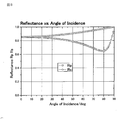
- FIG. 5 shows the incident angle dependence of the intensity reflectance of the ps polarization component in the sample shown in FIG.
- FIG. 6 shows the incident angle dependence of ⁇ in the Al sample at a wavelength of 405 nm as a complex plane display as an example of the incident angle dependence in the absorber sample.
- ⁇ ranges from 180 ° (corresponds to ⁇ 1 on the complex plane in FIG. 6) to 0 ° (corresponds to +1 on the complex plane in FIG. 6). ) Until a big change occurs.
- the polarization state changes from left-handed circularly-polarized light to right-handed circularly-polarized light as shown in the frame in FIG.
- the point of passing linearly polarized light at the incident angle is exactly the same as that of the transparent body. However, all the polarized light observed is tilted by an azimuth angle equal to ⁇ from the incident plane. In the example of FIG. 7, ⁇ always tilts by approximately 45 °, and the middle ellipse and linearly polarized light tilt uniformly by 45 ° as shown in FIG. 3 (even if the circle is tilted).
- the surface of the sample material can be regarded as a bulk.
- the method of the present invention is also effective when the sample surface is different from the bulk, for example, when the surface is covered with an oxide film or a cell membrane.
- the reflecting surface may be optically modeled to calculate the complex variable ⁇ , and associated with the observed change in polarization state.
- the methodology used in conventional ellipsometry can be used as is for this analytical calculation part. In other words, as long as the reflected light is reflected and the change in the polarization state of the completely polarized component can be observed, how to use the observed values and what information to extract can be obtained by introducing an ellipsometry technique. Good.
- the normal of the tangential plane at the reflection point (x 1 , y 1 , z 1 ) on the surface of the observation object The angle ⁇ 1 formed with a certain z axis and the deviation angle ⁇ 1 of the projection component onto the xy plane can be directly and precisely measured.
- the measured slope of the normal gives the partial differential coefficient at the reflection point (x 1 , y 1 , z 1 ) of the object.
- the construction of the three-dimensional shape can be obtained by integrating the measured partial differential coefficients over the entire observation surface. Further, focusing on the fact that the geometric shape does not depend on the observation wavelength, it is possible to extract and measure the physical optical characteristics of the reflecting surface.
- Devices known in the art implemented in robotics applications eg, D. Miyazaki, M. Saito, Y. Sato, K. Ikeuchi, “Determining surface orientations of transparent objects based on polarization degrees in visible and infrared wavelengths, "J. Opt. Soc. Am. A, 19 (4), pp. 687-694, 2002) can also be applied.
- the observation azimuth theory of the polarization ellipse is known. Although we have explained what can determine the orientation of the incident surface from the value, for example, as described below, a lighting device that can be switched between right circular polarized light and left circular polarized light, etc.
- the incident plane azimuth may be specified using the fact that the observed azimuth angle theoretical value switches symmetrically to the incident plane regardless of the reflection optical characteristics of the surface of the object.
- a shape / tilt detection and / or measurement optical device for detecting and / or measuring the surface shape / tilt of an observation object using the reflection optical characteristics of the surface of the object.
- an illumination device that surrounds the periphery of the object and injects light of a substantially known polarization state (for example, light in a completely polarization state) uniformly, and specularly reflects and specularly reflects on the object surface.
- a polarization image detection device that detects a polarization state of a light group emitted at an azimuth angle (for example, a polarization ellipse of a completely polarized component of the light group), and the object that forms an incident point for each reflected light beam
- Step 1 for knowing the orientation of the incident surface from the observation azimuth value of the polarization ellipse (for example, Step 1 for knowing the orientation of the incidence surface from the theoretical observation azimuth value of the polarization ellipse) and the ellipticity theory of the polarization ellipse
- the angle of incidence from the value In step 2 the tilt angle of the reflecting surface with respect to the exiting light beam is measured.
- the reflecting surface of the object that forms the incident point is incident from the azimuth angle of the polarization ellipse.
- the tilt angle of the reflecting surface with respect to the emitted light is measured.
- the right side of the illumination device that uniformly surrounds the periphery of the object and injects light in a substantially known completely polarized state
- the incident plane orientation is specified by using the observation azimuth angle theoretical value of the reflected polarization ellipse to be switched symmetrically to the incident plane regardless of the reflection optical characteristics of the object surface. It may be.
- the apparatus of the present invention may be a reduction optical system including a telescope or a camera, or may be configured as an expansion optical system such as microscopic measurement.
- the polarization image detection device that detects the polarization state of the light beam reflected on the object surface and emitted at a specific azimuth angle is, for example, a reduced projection image of the object.
- it has a mechanism for specifying the light beam position on the object surface by obtaining an enlarged projection image of the object, and further has a mechanism for specifying the light beam position on the object surface by providing a collimator and / or a pinhole. Can be.
- a polarization image detection device that detects the polarization state of a group of light beams reflected from the object surface and emitted at a specific azimuth angle specifies the light beam position on the object surface by placing the device substantially at infinity. It may have a mechanism to do.
- Light sources include left or right circularly polarized panels, left and right circularly polarized light switching panels, light emitting diode-equipped panels with polarizing films, etc., and also for optical microscopes, confocal microscopes, fluorescent microscopes, polarizing microscopes, etc.
- Typical light sources include halogen lamps, xenon lamps, deuterium lamps, global lamps, helium-neon (He-Ne) lasers, YAG lasers, light-emitting diodes (LEDs), semiconductor lasers, high-pressure mercury lamps, metal halide lamps, high-pressure sodium Examples include HID lamps (high intensity discharge lamps) such as lamps.
- the light source includes a plurality of light sources including the incident origin and the reference origin of the incident angle, such as a two-way light source method using a short wavelength laser light source such as a 408 nm purple laser diode and a white light source. Or a single light source.
- the light from the above-described light source is configured to transmit the 1/4 wavelength plate and the linear polarizer plate, or the linear polarizer film bonded with the 1/4 wavelength film,
- an object that can irradiate light from the above-described light emitting source through an object that surrounds the observation object may be included.
- the light emitted from the light source can be appropriately introduced into the incident light optical system through an optical fiber.
- the incident light optical system can be appropriately provided with a light intensity stabilizer, a light density filter, and the like.
- the light having a substantially known polarization state may be obtained by passing light emitted from a light source through a polarizer disposed in an incident light optical system.
- a wavelength plate may be used to convert linearly polarized light into circularly polarized light and / or circularly polarized light into linearly polarized light, or rotate the polarization axis of linearly polarized light.
- Incident light that is, illumination on the sample is irradiated so as to be uniform from the periphery of the sample.
- the illuminating device constituting the incident optical system is configured so that the polarized light can be incident substantially uniformly around the periphery of the object as the sample.
- the incident optical system may be controlled by a control system linked with a computer so that light can be incident substantially uniformly around the periphery of an object as a sample.
- a control system linked with a computer so that light can be incident substantially uniformly around the periphery of an object as a sample.
- a control system linked to a computer for example, an image that can be scanned by dividing the observation field into an appropriate number of pixels may be included.
- the light beam reflected from the object surface can be detected as a polarization image by a polarization image detection device such as a polarization imaging camera, but is introduced into a detection optical system equipped with an analyzer to detect the polarization state. There may be.
- the reflected light received by the detection optical system including the analyzer is supplied to the photodetector after passing through a spectroscope that may include a monochromator tuned to the optical band of the light source, and is received by the light receiving element. It may be detected.
- the spectrometer allows spectral analysis of the received light. That is, it is possible to detect the received light while changing the detection wavelength.
- An optical fiber can be used to guide light to a predetermined device.
- optical fibers provides the advantage that the moving parts of the device and / or the moving device can be configured to move independently and freely.
- the light can be converted into an electric signal by an optical sensor including a light receiving element.
- the photosensor may include, for example, a photodiode, a diode array, a charge coupled device (CCD) image sensor, a CMOS image sensor, and the like, and further includes a photomultiplier tube (photomultiplier). , PMT).
- a wave plate For the incident light optical system in the illumination device and the detection optical system in the polarization image detection device, a wave plate, a compensator (compensator), a modulator such as a photoelastic modulator, a mirror for guiding light rays, as appropriate.
- a slit for example, a filter, a lens (for example, a condensing lens), a transparent plate, a polychromator, and the like can be provided.
- the analyzer can be constructed using a polarizer.
- a monochromator can also be disposed in the incident light optical system.
- the polarizer of the incident light optical system and / or the analyzer of the detection optical system may be movable by the drive unit.
- the analyzer may be one that is rotated under the control of a driving device under the control of the following computer system so that the polarization state can be analyzed.
- the wave plate may also be movable by a driving unit.
- a drive unit including a rotation mechanism may be provided on the observation sample mounting table, and the entire incident light optical system and / or the entire detection optical system may be movable by the drive unit.
- the present invention can suitably employ a method that does not perform scanning.
- the image signal is analog, it can be converted to digital as necessary by a converter.
- the signal is sent to a computer system and attached to a calculation means to calculate the azimuth and incidence angle of the incident surface, and the vicinal surface of the observation target object that is the surface of the material as the sample and reflects the incident light, That is, the inclination of the tangent plane is determined, and the shape of the object including the three-dimensional shape is reproduced.
- the reproduced shape is made visible and / or recognizable using a display device and / or an output device constituting the computer system.
- the computer system includes a data storage device and an arithmetic device, and includes, for example, a hard disk and a CPU, and may further include a writing and / or reading device such as a CD, MO, or DVD.
- the driving unit of the observation sample mounting table may be able to move independently and freely along the x-y-z axes under the electronic control of the stage controller of the computer system.
- An auto stage can also be used suitably.
- the setting of the continuous rotation of the polarizer is made possible under the electronic control of the computer system, while using a rotating analyzer.
- the setting of the analyzer rotation may be made under electronic control of the computer system.
- the wave plate may be provided and moved so that it can be performed under electronic control of the computer system, which may be preferred.
- a stepping motor is electronically controlled and moves by the stepping motor. Operation data together with position information thereof may be collected in the computer system.
- control device of the computer system may act on the monochromator to determine its tuning wavelength, or to act on the light source to control the luminous flux, etc.
- Control of recording of collected data such as polarization state information including shape information, measurement position information, and the like may be included as appropriate and supplied to a computing device (eg, CPU) of a computer system.
- This computer system is provided with a predetermined data processing program, uses the collected data according to any appropriate program, and reconstructs the measured image.
- the processing program includes a function for comparing and calibrating measurement data under incident light in a polarization state and measurement data under incident light that is not in a polarization state, and sufficient data for characterizing the data.
- a function to collect data until it is accumulated a function to construct a shape including a three-dimensional shape from integrated data, a function to display and / or output to a display device and / or an output device, and an analysis using an optical model based on optical theory That fulfills the function to perform.
- it may include comparing the data obtained by the optical model with measured data and analyzing with a regression analysis algorithm.
- illumination light only needs to have a known polarization state.
- elliptical polarization or linearly polarized light is used as illumination light. It can also be used as a configuration.
- linear polarizers can be manufactured in any wavelength range.
- the recently reported axially symmetric polarized beam (axially symmetric polarized beam, Yuichi Ozawa, Shunichi Sato, Optics, Vol. 35, No. 12 (2006), pp. 9-18: Non-patent document 3) should be used as illumination light. You can also.
- the axisymmetric polarized beam can be easily obtained using a photonic crystal optical element.
- a concentric or radial polarized beam can be obtained by using a concentric photonic crystal polarizer as the output mirror of the laser generator.
- the reflectance can be easily adjusted, so that the reflectance suitable for laser oscillation can be obtained, and since the constituent material is an inorganic material, high durability performance can be obtained.
- Axisymmetric photonic crystals are laser resonator half mirrors that oscillate concentric or radial polarized beams, polarizers with concentric or radial transmission axes, and convert linearly polarized light into concentric / radial polarized light. Waveplate integrated elements and the like may be included.
- the techniques of the present invention may also include methods and apparatus that simultaneously determine optical properties with epsometry.
- the illumination device in the shape / tilt detection and / or measurement optical device of the present invention includes a spatially specified incident ray as a measurement reference origin, and an observation value of a polarization ellipse at a reflection point specified by the polarization image detection device. Therefore, the optical property of the reflecting surface can be specified. If comprised in this way, it is possible to carry out an epsometric measurement at one point in a polarization image by changing a color or making a hole in illumination.
- the tilted ellipsometry of the present invention encompasses measurement applications with non-polarized illumination in robotics applications.
- the principle of tilted ellipsometry of the present invention can be explained in a form including a partial polarization state using Stokes parameters and Mueller matrix.
- the reflection on the sample surface includes a scattering process, the reflected light is partially polarized.
- the change in polarization state due to reflection is more generalized and uses Stokes parameters and Mueller matrix that can describe unpolarized light and partially polarized light.
- the Mueller matrix representing the reflection of polarized light at the incident angle ⁇ 1 on the vertical sample surface where the incident surface is horizontal is
- the change due to the inclination ⁇ 1 of the incident surface is merely a rotation of S 1 and S 2 coordinates ⁇ 1 around the Poincare sphere with S 3 as the rotation axis, and the ellipticity angle is not changed. If non-polarized light is incident, reset the incident Stokes parameter to non-polarized
- the shape measurement in the robotics field uses the incident angle dependence of the degree of polarization.
- the degree of polarization V of the partially polarized light is expressed as a ratio of the completely polarized component to the partially polarized light.
- the degree of polarization is a real number, and of course, the measurement method is limited in application compared to the method of using the information of two variables of the polarization ellipse of the present invention for measurement.
- the reason why the application range of shape measurement under non-polarized illumination is limited to a transparent object is the limited measurement condition that utilizes the incident angle dependence of the absolute value of ⁇ 1 .
- it is a treatment function with a minimum value, there are two incident angles that give the same degree of polarization, and it is necessary to devise an algorithm that discriminates the true value (D. Miyazaki, M. Saito, Y Sato, K.
- ⁇ 1 can be determined with a sign, so these algorithms are not necessary.
- the absorption is large, as shown in FIGS. 6 and 7, the dependence of ⁇ 1 on the incident angle is generally small. Therefore, with such a sample object, shape measurement by non-polarized illumination for robotics application cannot be performed.
- light having a wavelength at which the object is transparent is used.
- the light having a wavelength with which the object is transparent is a case where the extinction coefficient k of the imaginary part of the complex refractive index n ⁇ ik is small.
- the target object is Si or the like
- the object is transparent in the infrared region.
- Measurement with unpolarized illumination is, for example, when measuring with a light source that cannot be polarized, such as sunlight, and according to the theoretical system disclosed by the present invention, the wavelength to be detected is set to a wavelength at which the object is transparent. It is clear that measurement sensitivity can be improved. As described above, since information on ⁇ is lost in non-polarized illumination, the incident angle dependence is measured only with information on ⁇ .
- phase shifter is required to confirm that the illumination light is non-polarized light.
- all materials are transparent in the soft X-ray region.
- Polarizers and phase shifters have also been developed in the soft X-ray region, and detection and / or measurement of the present invention can be performed with a synchrotron radiation light source, a laser-generated plasma soft X-ray light source, or the like. In such a case, since the reflectance of the substance is extremely small, it is preferable to mainly use a region near grazing incidence.
- the present invention provides an object information extraction method, that is, an optical shape / tilt detection and / or a method for detecting and / or measuring a surface shape / tilt of an observation object using reflection optical characteristics of the surface of the object.
- a measurement method is provided.
- the method is an optical shape / tilt detection and / or measurement method for detecting and / or measuring the surface shape / tilt of an observation object using reflection optical characteristics of the surface of the object.
- Light with a known polarization state that uniformly surrounds the periphery is incident uniformly, and the polarization state of a light beam reflected at the object surface and emitted at a specific azimuth angle is detected by a polarization image detector, and reflected and emitted.
- the method may further detect and identify a specific change in the surface inclination angle caused by various lesions such as a malignant tumor using a human body such as a human body or a breast as a detection and / or measurement object.
- the method also includes a method in which a predetermined deformation is given according to a change in posture of an observation object such as a patient, and a change in tilt angle before and after the deformation is detected and / or measured.
- the change in the optical characteristics of the reflecting surface is detected as a substantial reflecting surface considering that the penetration depth from the surface of the observation object including the skin changes with the wavelength using the illumination light as white light. It may be one that measures.
- the application of the present invention is not limited to the application described above.
- Surface tilt angle data that can be measured by tilt ellipsometry can be applied not only to shape measurement but also to database construction by sampling object shapes and statistical processing.
- the gradient ellipsometry the inclination of the surface is recorded even when the magnification is changed, so that only the information on the shape is extracted. Therefore, the shape can be standardized even if the size changes due to individual differences.
- wavelength is not limited: white circularly polarized light can be used>
- the gradient ellipsometry method of the present invention can be applied to all electromagnetic waves.
- white light can be used as it is. Therefore, if the shape is measured at a wavelength such as ultraviolet light having a large absorption coefficient and a small light penetration depth, the surface region characteristics within the penetration depth range can be evaluated from the measurement results at other wavelengths.
- the wavelength dispersion of the complex refractive index can be described by a dispersion equation of about three variables, so that the optical characteristics of the surface can be known in more detail.
- the tilt angle measurement of the tilt ellipsometry of the present invention is sensitive to the incident angle, and has no sensitivity to the horizontal shift and vertical shift components caused by vibrations caused by disturbance. Therefore, it is suitable for precision measurement in a normal environment.
- ⁇ Suitable for precision tilt measurement in normal environment Local deformation can be extracted with the first derivative of tilt change>
- the inclination can be directly read by applying to observation of a part such as a human body or a breast. Malignant tumors and the like are different from normal cells in the tissue and mechanical properties under the skin, and are uneven. Therefore, although diagnosis is made by a palpation by a doctor, local deformation such as slight depressions and bumps can be easily detected as a differential amount of data by applying the tilt ellipsometry of the present invention.
- the deformation state can be clearly distinguished from the normal cell portion.
- a constant pressure can be applied to the skin using a gas flow or the breast surface can be scanned as necessary.
- a deformation abnormality in a deeper part can be found by applying a larger pressure change using the liquid flow and observing.
- the observation wavelength it may be possible to detect the characteristics of the vascular tissue that has developed around the tumor.
- a light scattering measurement method that actively incorporates the scattering phenomenon and the coherence of illumination light has been developed.
- new research progress can be made by incorporating the fact that “the optical characteristics of the completely polarized component of the reflected partial polarized light have a characteristic incident angle dependency” disclosed in this specification.
- ⁇ Time change can be easily recorded: suitable for dynamics observation>
- the tilt can be read directly at the same time as the image acquisition, it is possible to detect a local fine deformation in the image by recording the time change.
- This function can be developed for applications such as capturing precursors in studying dynamics such as cell division and apoptosis.
- An example belonging to the first embodiment of the present invention is a shape measuring telescope as shown in FIG.
- the first embodiment is a case where the illumination light is right or left circularly polarized light.
- the second embodiment left and right circularly polarized light is switched.
- the first embodiment is a case where the illumination light is right or left circularly polarized light.
- left and right circularly polarized light is switched.
- the gradient ellipsometry in the present invention is a common property of all substances.
- In-situ observation data of tilt can be used directly, and 3D shape measurement that reconstructs the shape of the sample by smoothly connecting the reflection surface of the measured reflection point between the measurement points in the sample cross section.
- the three-dimensional shape measurement application can be used for applications, etc., and the accuracy of the existing methods of robotics applications, which are developing limited to transparent objects with non-polarized illumination, is improved with complete polarized illumination, making it simple and versatile It provides shape / tilt detection and / or shape measurement and analysis techniques.
- FIG. 9 shows an apparatus with the simplest configuration for the shape measuring telescope. This configuration can be applied to a reduction optical system apparatus and, of course, can be applied to a camera or the like.
- the illumination device in the shape / tilt measuring optical device of the present invention is shown as a circularly polarized illumination device in FIG.
- the circularly polarized illumination device can be realized by surrounding the sample with a circularly polarized panel.
- a circularly polarizing panel may be composed of elements similar to a liquid crystal panel, and includes, for example, a light source such as a light emitting diode, a diffusion plate, a linearly polarizing film, and a retarder film, and has uniform brightness. What constitutes a circularly polarizing panel is included. Practically, a circularly polarizing panel may be configured by sticking a retarder film in a predetermined orientation on the surface of a liquid crystal panel that is linearly polarized illumination. If a diffusing plate is used to form an illumination panel with uniform brightness in the plane, the brightness is determined regardless of the observation direction by the principle of photometry, and the shape cannot be discriminated. Therefore, for example, the lighting device may be a box shape constituted by a panel. In practice, a liquid crystal panel may be used on each side to make a box shape, and a sample may be placed therein.
- the polarization image detection apparatus in the shape / tilt measurement optical apparatus of the present invention is shown on the right side in FIG.
- a polarization imaging camera [Photonic Lattice Co., Ltd. (Aoba Ward, Sendai City, Miyagi Prefecture)] equipped with a 2D polarization detector can be preferably used for polarization image detection.
- the polarization image detection can be preferably performed using a photonic crystal element, and may be performed using a charge coupled device (CCD).
- CCD charge coupled device
- the camera can send image signals to a personal computer (computer) via a USB cable and process them with appropriate software.
- the photonic crystal element examples include a polarizer array (patterned polarizer), a ⁇ / 4 wavelength plate array (patterned wavelength plate), and the like.
- the polarization imaging camera may be configured using one selected from the group consisting of a collimator, a prism, a wave plate array, a polarizer array, and a CCD.
- the image information can be taken in parallel in space.
- the thing of a typical aspect can process the image for every pixel, and can perform machine recognition of image data.
- the polarizer array may be, for example, a chip in which about one million or a predetermined number of polarizers having the same size as the pixels are arranged.
- the polarizer array approximately square polarizers having slightly different transmission axis directions are spread, and by calculating the luminance of four adjacent pixels of the polarizer array, the main axis direction of polarization, average luminance, polarization The thing which can obtain the strength of a component instantly is mentioned.
- the polarizer array may have a configuration in which vertically long polarizers having slightly different transmission axis directions are arranged side by side, and the wavelength plate array may have a configuration in which horizontally long wavelength plates are arranged in the vertical direction. .
- a photonic crystal is a structure in which materials having different refractive indexes are periodically arranged, and is a multidimensional periodic structure such as two-dimensional or three-dimensional.
- the period of the structure is usually designed to be about half of the wavelength of light to be used. For example, when used in the visible light region, the photonic crystal is designed and produced so that the period is about 300 nm.
- the periodic structure of the photonic crystal is called “crystal”, but the periodic structure of the photonic crystal is about several hundreds of nanometers, and the “photonic band” in the wavelength band through which light is transmitted,
- a structure in which “photonic band gaps” in the wavelength band that blocks light transmission are arranged and / or stacked, that is, two types of dielectrics of high refractive index and low refractive index are self-retaining with certain irregularities It is a multi-dimensional structure in which multiple layers are molded.
- a typical photonic crystal is a technology that forms a multi-dimensional stacking / pattern such as a steady three-dimensional uneven pattern by combining sputter lamination and bias etching on a patterned uneven substrate, for example, a self-cloning method.
- the photonic crystal element has a function of controlling light transmission / reflection / refraction characteristics.
- Two-dimensional distribution data of Stokes parameters is output from the 2D polarization detector of the camera via a data processing unit, and a subsequent data processing system, a display device, a data storage device, etc. are arranged, and necessary processing is performed. Is possible.
- a data processing unit a data processing unit, and a subsequent data processing system, a display device, a data storage device, etc. are arranged, and necessary processing is performed. Is possible.
- a display device e.g., a display device, a data storage device, etc.
- a reduction optical system such as a telescope generally has such a configuration, and the opening angle of a light beam that diverges from one point on an object used for imaging is sufficiently small, so that the polarization state may be regarded as uniform.
- FIG. 10 shows an apparatus with the simplest configuration with respect to the shape measuring microscope.
- This configuration can be applied to a magnifying optical system device, and is not particularly limited as long as the object can be achieved, and can be applied to various devices.
- a magnifying optical system such as microscopic measurement
- increasing the NA (Numerical Aperture) of the optical system increases the opening angle taken into the imaging system out of the light flux diverging from one point on the sample. Since the change in the polarization state at 1 becomes significant, generally, a configuration as shown in FIG. 10 is used.
- the NA of the optical system is increased to increase the resolution of the image.
- increasing the NA increases the angle of capture of the component reflected at one point on the sample, so that the incident angle also increases and the resolution for the polarization state, which is a function of the incident angle, decreases.
- the polarization resolution pinhole is inserted and used when it is desired to increase the resolution of polarized light.
- FIG. 10 it is possible to extract a light ray component indicated by a thick solid line.
- the measurement is performed by superimposing the polarization-resolved image obtained by inserting the pinhole on the image with high spatial resolution obtained by removing the polarization-resolution pinhole.
- this pinhole can also be achieved by using a photonic crystal wave plate array in which two quarter wave plates having orthogonal anisotropic axes are integrated.
- two types of wave plates with different anisotropy axes are joined in a form that has substantially no joining boundary, that is, a polarizing vertical slit (Photonic Lattice Co., Ltd. (Aoba Ward, Sendai City, Miyagi Prefecture)) is used. It may be.
- the imaging optics can be omitted. In this case, a simpler configuration may be used. Whether it is enlarged or reduced, the position of the pinhole and detector can be selected freely. See FIG.
- the illumination device, the polarization image detection device, the data processing system, and the like can be configured in the same manner as in the first embodiment.
- the shape / tilt measurement optical apparatus of the present invention may be an apparatus as shown in the block diagram of FIG. 12 or 13, for example. It should be understood that both can be configured by a combination of known techniques, and many modifications and variations are possible. These optical systems and the optical system of the collimator may be configured by lenses, but in an optical system using white light or multiwavelength light, the optical system may be configured using a mirror. In the case of the configuration shown in FIG. 12, changes in the phase and amplitude on the mirror surface are measured and corrected in advance if necessary.
- the folding reflecting mirror may have an opening at the center.
- a reflection imaging system, a beam expander, or the like may be included as an optical system between the polarization illumination device and the polarization image detection device.
- an imaging optical system, a perforated plane mirror, or the like may be included as an optical system between the polarization illumination device and the polarization image detection device, and an intensity image detection device or the like may be further included.
- the shape / tilt detection and / or measurement optical device of the present invention may be a device as shown in the block diagram of FIG. 14 or 15, for example.
- the shape / tilt detection and / or measurement optical device of the present invention can be configured as a medical diagnostic device including mammography.
- the medical diagnostic apparatus detects and identifies a specific change in the surface inclination angle caused by various lesions including a malignant tumor, for example, by detecting and / or measuring a part of the human body including the human body or breast. Can be.
- the shape / tilt detection and / or measurement optical apparatus applies a predetermined deformation by a process including a change in posture of an observation object including a patient, and detects and / or measures a change in inclination angle before and after the deformation. It may be characterized by.
- the predetermined deformation may be a change in pressure on the skin caused by a gas flow or a liquid flow.
- the shape / tilt measuring optical device of the present invention uses the illumination light as white light, and reflects the reflection as a substantial reflecting surface considering that the penetration depth from the surface of the observation object including the skin changes with the wavelength. Including those characterized by detecting and / or measuring changes in optical properties of a surface.
- a configuration as shown in FIG. 14 can be cited, and it is conceivable that the lighting device is finished in a bed shape having two openings, and the patient takes a prone posture at a predetermined position on the bed.
- the detection unit is filled with a liquid that matches the body temperature, and the breast is encased in the liquid.
- a deformation abnormality in a deeper part is found. I can expect that.
- a configuration as shown in FIG. 15 can be cited, which can be constructed by pressing the chest against a cylindrical examination unit.
- the illumination device, the polarization image detection device, the data processing system, and the like can be configured in the same manner as in the first embodiment.
- This mammography application can be used as an auxiliary device for visual observation that makes it easy for doctors to detect slight depressions and the like. The detection only needs to have a function of converting the unevenness of the affected area into contrast of light and dark, and does not necessarily require quantitative measurement.
- the affected area is illuminated with right-handed circularly polarized light, and an elliptical polarizer composed of a combination of a quarter-wave plate and a linear polarizer, each of which can be rotated by a doctor, is worn like glasses.
- the present invention can be used by making it possible to observe the fine unevenness of the affected part as a change in strength with the naked eye.
- the spectacles are used for eyesight tests in ophthalmology, using a type that can replace two lenses and mounting a quarter-wave disk and a linear polarizer disk instead of the two lenses. It's okay.
- the doctor observes the affected area, for example, with the azimuth angle configuration of the left circular polarizer, and changes the elliptical shape of the elliptical polarizer to the extinction state by rotating the azimuth angle of the quarter wave plate and the linear polarizer as necessary. It may be possible to make a detailed observation using a state where the contrast of the shape change is high. Moreover, the thing of the structure which automates rotation of the azimuth of a quarter wave plate and a linear polarizer, and images with a video camera is also included. Such an apparatus can perform magnified observation and other image processing on the screen.
- the circularly polarized illumination may be a transparent circularly polarizing cylinder created by laminating a 1/4 wavelength film to a linear polarizer film, and the affected area may be illuminated with normal illumination from the outside.
- the walls of the room may be composed of circular polarizer panels, and various devices can be applied so as not to cause a mental burden on the patient.
- the shape measuring optical device of the present invention may be, for example, a device as shown in the configuration diagrams shown in FIGS.
- the principle of ellipsometry of the prior art can be used for detecting the polarization state.
- the sign of ellipticity angle that is, polarization measurement when there is no need to distinguish clockwise polarization and counterclockwise polarization, and when measurement including the sign of ellipticity angle is required
- the detection is performed by detecting the value of S 1 or S 2 on the surface of the Poincare sphere perpendicular to the S 3 axis with a constant ellipticity angle or its ratio. To do. Information of S 3 or because it does not require the rotation direction of the information of the ellipse, and does not require a phase element such as a 1/4-wave plate.
- a phase optical element such as a quarter-wave plate for discriminating the rotation direction of the ellipse including S 3 is included in the detection optical system, and belongs to the “rotational phaser method” that can detect the Stokes parameter. Use detection technology. For these measurements, the existing ellipsometry technology described above may be applied.
- the mechanical drive unit in applications that require high-speed reading, it is desirable that the mechanical drive unit be eliminated even in the case of (A) rotating element type detection.
- the polarization state is modulated using a polarization modulation element using various polarization modulation effects such as the Faraday effect, Kerr effect, and Pockels effect, and the phase angle of the cos ⁇ signal is determined and detected by a lock-in detection method. It can also be taken.
- the method of dividing the reflected light into a plurality of spaces and assigning a plurality of analyzers capable of detecting a specific polarization state and simultaneously detecting the polarization state in parallel is further superior from the viewpoint of speeding up.
- a linear analyzer with a different azimuth angle ⁇ is assigned to each channel of a detector having a plurality of channels, and a rotational phaser signal is detected simultaneously, and the phase angle of the cos ⁇ signal (azimuth angle of the main axis of the ellipse) is detected by signal processing.
- a multi-bit signal having the required number of significant digits. Install at least three channels. The measurement accuracy may be improved by increasing the number of channels.
- the detection azimuth angles of each channel are based on an arrangement that is as far apart as possible on the S2 and S3 surfaces of the Poincare sphere and is equally spaced from each other.
- the orthogonal linearly polarized image detection unit (orthogonal unit) shown in FIG. 16 is used for one channel of the two-dimensional polarization detector.
- a polarized beam emitted from an object is divided into a p-component that travels straight by a polarization beam splitter and an s-polarized component that is reflected, and an object image is formed on a two-dimensional detector by an imaging lens. Extracted as image output.
- the unit surrounded by the broken line is hereinafter referred to as “orthogonal unit”.
- the two polarized images output from this orthogonal unit are located at symmetrical points on the Poincare sphere.
- the detected polarization state is composed of an image by horizontal linearly polarized light (front channel) and a vertical linearly polarized image (back channel).
- the detection azimuth is 60 ° on the Poincare sphere as a reference, for example, 0 ° (back 180 °), 60 ° (back 240) °), 120 ° (back 300 °).
- the azimuth angle of the real space is halved, 0 ° (back 90 °), 30 ° (back 120 °), 60 ° (back 150 °).
- an azimuthal rotation of 180 ° is completely equivalent as a polarization state and cannot be distinguished. Therefore, in an actual real space arrangement, it may be set to 120 ° equidistant from 0 °, 120 °, and 240 °.
- a phase plate such as a quarter-wave plate
- a predetermined elliptic analyzer is placed in each channel, so that the signal contrast for each channel can be increased. It can also be optimized.
- the number of channels is determined with the required measurement accuracy. For example, if the number of channels is 15, 30 pieces of image information are obtained, and a measurement accuracy of 1/1000 ° is obtained.
- a signal with the phase of the polarization state changed is obtained using a phase shifter such as a quarter-wave plate.
- a configuration in which a mechanical drive unit for detection of the rotational phaser type is excluded is desirable.
- the configuration of the detection system is in principle the same as the configuration in (A), and specific analyzers are arranged in a plurality of channels.
- the analyzer in this case is an elliptical polarization analyzer that is orthogonal to a specific elliptical polarization state, including a linear polarizer and a circular polarizer.
- the optimum arrangement can be devised in the distribution region so that the maximum sensitivity can be obtained with respect to the distribution of the polarization state to be detected on the Poincare sphere.
- the number of detection channels on the Poincare sphere is at least three based on the principle of triangulation.
- Each channel is located at a specific detection coordinate on the Poincare sphere, and the channel output may be considered to be proportional to the distance from the detection coordinate.
- the channel output may be considered to be proportional to the distance from the detection coordinate.
- an elliptical analyzer image having the same ellipticity in the northern hemisphere and an azimuth angle orthogonal to real space is output to the back channel. If the polarization state is all over the Poincare sphere, S1, S2, S3, and points on the axis that are orthogonal on the Poincare sphere may be taken, but the equidistant triaxial 0 in the real space described in (A)
- a four-channel configuration with a left circular polarizer of -S3 in addition to linear polarizers of °, 120 °, and 240 ° is one optimal solution.
- FIG. 17 shows a basic configuration for measuring the Stokes parameters of a two-dimensional image.
- a portion surrounded by a broken line is an orthogonal unit for detecting circularly polarized light, and is composed of a quarter-wave plate and an orthogonal unit.
- a quarter wavelength prism using a total reflection phase jump with little wavelength dependency may be used instead of a normal quarter wavelength plate.
- the partial reflection mirror inserted in the optical axis is used at a reflection angle as close as possible to normal incidence or oblique incidence in order to reduce polarization characteristics. From the light source side, the reflectance is 1/3, 1/2, and light is equally distributed to 3 orthogonal units by 1/3 each, (horizontal linearly polarized light component S 1 , vertical linearly polarized light component ⁇ S 1 ), respectively.
- (+ 45 ° linear polarization component S 2 , ⁇ 45 ° linear polarization component ⁇ S 2 ) and (right circular polarization component S 3 , left circular polarization component ⁇ S 3 ) are detected.
- the number of channels is increased in order to increase the measurement accuracy of the Stokes parameter.
- it may be divided by a partial reflecting mirror along the optical axis, but the prism method is suitable for more precise division.
- a total of 18 polarized image outputs are obtained.
- 36 practically sufficient rotational phaser type image outputs can be obtained.
- the technology of the present invention needs to ensure the accuracy of polarization measurement in a range of light beams having a polarization state substantially the same as the polarization state of the light beam reflected in the observation direction out of the reflected light beam spreading from the reflection point. It is a technology that satisfies. For example, if the polarization camera is sufficiently far away, no special device is required, but the spatial resolution of the image is reduced. On the other hand, if the polarization camera is close, the spatial resolution of the image can be sufficiently increased, but the measurement accuracy of the polarization state is lowered. In order to make both compatible, for example, an apparatus provided with a polarization resolution pinhole as shown in FIGS. 10 and 11 or a perforated plane mirror as shown in FIG. 13 is useful. Similarly, if the NA of the detection system is made smaller, the resolution of the incident angle measurement value can be increased. Therefore, what employ
- a circularly polarized light illumination device including the incident light component of The object surface to be measured may include the inner surface of the object.
- the circularly polarized illumination device is directed to a light source device that supplies illumination light to an illumination section that forms a concave surface surrounding the outer surface of the object to be measured or a convex surface directed toward the inner surface, and an object generated by the light source device. It has an illumination section that allows the light beam to pass circularly polarized light.
- the circularly polarized light illuminating device makes circularly polarized light incident on an inclined surface constituting an object surface including an inner surface, and uses the polarization characteristics of reflected light that is regularly reflected in a specified observation direction. It is used for an inclination / shape measurement method for measuring a three-dimensional inclination angle of a surface and a shape / inclination of the object constituting the inclined surface.
- This circularly polarized illumination device comprises a plane or curved surface that faces the object so that the group of circularly polarized light incident on the object surface includes all incident light components that can be regularly reflected in the observation direction according to the law of reflection.
- It has a polyhedral-shaped illumination section that is circular or rectangular, and a combination thereof, and the section is configured by a concave surface that surrounds the outer surface of the object, or a convex surface that faces the inner surface of the object, and is substantially directed toward the object through the section.
- a light source device capable of irradiating a perfect circularly polarized light.
- the principle of tilt measurement of an object plane by polarized light which is a technical area related to the present invention, belongs to the precision optical measurement technology newly invented by the inventors and proposed as “3D tilt ellipsometry”.
- the technical requirements include the specification of Japanese Patent Application No. 2008-211895, which is the basic application for priority claim [Patent Document 7], and “Inclined ellipsometry of the object surface by specular reflection-Basic concept for precise real-time shape measurement-”, optical , Vol. 38, No. 4 (2009) [Non-Patent Document 7].
- ellipsometry obliquely enters polarized light on a flat (thin film) sample and accurately measures the polarization state of “specularly reflected light” that is specularly reflected according to the law of reflection. It is known as a method that can accurately measure the thickness.
- This prior art ellipsometry technique is limited to planar samples.
- the sample surface is incident so that the normal line is within a predetermined incident surface and at the same time the incident angle satisfies the law of reflection with respect to the incident light optical axis and the reflected light optical axis of the ellipsometer. Adjust the in-plane tilt.
- the incident angle and the incident surface azimuth angle of the light at the time of measurement are set as known variables and are fixed during the measurement.
- an arbitrary minute reflecting surface that forms a part of a three-dimensional surface with an arbitrary orientation is rotated by an azimuth angle - ⁇ with the z axis as the rotation axis.
- the incident surface can be made to coincide with the 19 paper planes.
- the incident surface is defined as a surface including an incident ray and a normal of the reflecting surface, and a normal vector perpendicular to the reflecting surface is always included in the incident surface.
- a line vector is determined. If the normal can be determined, the shape can be reconstructed by integration.
- the azimuth angle ⁇ and the incident angle ⁇ of the incident surface can be determined from the azimuth angle and ellipticity angle of the polarization ellipse observed by “3D tilt ellipsometry”.
- the ellipse of reflected polarized light observed from the z direction under circularly polarized illumination can be illustrated as shown in FIG.
- the major axis of the ellipse is inclined by 90 ° from the p direction of the incident surface, so that the minor axis of the ellipse always coincides with the p direction of the incident surface (the upper diagram in FIG. 20). Accordingly, it is possible to directly read the incident surface azimuth angle (azimuth angle with the z axis as the rotation axis) including the normal vector.
- the major axis of the ellipse is always inclined by about 45 ° as shown in the lower diagram of FIG.
- the offset angle of the major axis of the ellipse is a constant determined by the optical characteristics of the reflecting surface and can be obtained by ellipsometry calculation. Therefore, the normal vector azimuth can be determined from the ellipse major axis azimuth for all materials.
- FIG. 21 shows a conversion table of observed ellipticity angle and incident angle cosine at right circularly polarized light incidence.
- the incident angle cosine coincides with the z component of the direction cosine of the unit normal vector of the reflecting surface.
- most substances have a conversion curve between a solid line (metal) and a broken line (dielectric).
- the ellipse illustrated in FIG. 20 shows a case where the incident angle ⁇ of FIG. 21 is less than 60 °, and is a clockwise ellipse for a dielectric and a counterclockwise ellipse for a metal. In this way, the incident angle cosine can be directly read from the ellipticity angle.
- the sign of the ellipticity angle is determined by the rotation direction of the ellipse, positive in the clockwise direction and negative in the counterclockwise direction.
- the incident angle range (0 ° to 90 °) of the conversion table coincides with the ellipticity angle range ( ⁇ 45 ° to + 45 °). Therefore, the normal vector of the reflecting surface can be accurately determined with the same angular accuracy from the azimuth angle and ellipticity angle of the elliptically polarized light of the regular reflection light.
- FIG. 22 shows an experimental apparatus used for a measurement experiment conducted based on the disclosure of Japanese Patent Application No. 2008-211895, which is a basic application for claiming priority.
- the circularly polarized illumination was manufactured by inserting a circularly polarized film into a commercially available dome-shaped illumination.
- the polarization ellipse of specularly reflected light was observed using a rotating analyzer method by combining a polaroid sheet polarizer (analyzer), an interference filter for a wavelength of 633 nm, and a CCD detector. .
- the observation results of the prismoid and hemisphere are shown side by side on the left and right sides of FIG. From the top, a) the observed ellipticity angle, b) the observed azimuth angle, and c) the sample photograph.
- the gray scale of the observed ellipticity in FIG. 23a) shows a range of 5 ° to 35 ° in the left figure and 10 ° to 35 ° in the right figure.
- the observed ellipse is counterclockwise and the ellipticity angle is in the negative region, but it is positive because it is measured by the rotating polarizer method and cannot be discriminated clockwise or counterclockwise. Further, in the right hemispherical sample, the region near normal incidence and the oblique incidence region where the sample periphery is sharp are not observed due to lack of illumination light that can be spatially regularly reflected.
- the configuration of the circularly polarized illuminator suitable for 3D tilt ellipsometry observes as complete circularly polarized light as possible in order to accurately transfer the tilt information of the object surface to the reflection ellipse. It is necessary to include it as an incident light component that can be reflected as a possible regular reflection component.
- the measurement sensitivity is essentially determined by the measurement sensitivity of ellipsometry measurement.
- the transmission intensity is
- This intensity change follows the well-known cosine square law according to the well-known Malus law shown by a solid line in FIG.
- This change in intensity reaches several digits as indicated by a broken line when expressed in logarithm according to the scale on the right vertical axis.
- the intensity change near the extinction position at an azimuth angle of 90 ° is abrupt, and extinction by a polarizing prism with a good extinction rate attenuates even laser light to the extent that it can be observed with the naked eye.
- the intensities of the components of the p-polarized light and the s-polarized light reflected from the sample surface are equal, and the main axis of the reflected elliptically polarized light has an azimuth of 45 ° regardless of the value of ⁇ . It becomes. Therefore, an ellipse having an arbitrary ellipticity angle is converted into linearly polarized light that is inclined by an ellipticity angle from the neutral axis of the quarter-wave plate by the quarter-wave plate fixed at an azimuth angle of 45 °. At this time, the ellipticity angle is equal to ⁇ / 2, and ⁇ is determined from the azimuth angle of A that is quenching linearly polarized light.
- the determination accuracy of the extinction azimuth is determined by the sharpness of the depression.
- the minimum value of the transmission intensity at this extinction position is determined by the extinction performance of the polarizer.
- the performance of a polarizer is the extinction ratio defined by the ratio of the minimum transmission intensity to the maximum transmission intensity.
- the detection sensitivity is determined by the detectable rate of change in intensity.
- the linearly polarized light generated by the polarizer being a partially linearly polarized light that contains a non-polarized component
- the light of Scattered indicating that certain unpolarized components pass through the analyzer.
- the sensitivity characteristics at the time of extinction of ellipsometry are equally established even when the shape of the completely polarized light component is arbitrary elliptically polarized light including circularly polarized light, because the phase shifter acts to make linearly polarized light.
- the measurement error is the polarization
- the polarization ability of a circular polarizer is determined by the polarization ability of the polarizer used. In addition, due to the following factors, the polarization state depends on the irradiation angle, and the polarization state changes from circularly polarized light except for normal incidence. This is a factor that degrades the degree of polarization of the light to be imaged at the image forming position. 1.
- the allowable angle range of the polarizer is limited, and the maximum is ⁇ 15 ° for the Glan-Thompson prism type. (Reference: http://www.b-halle.de/EN/Catalog/Polarizers/Glan-Thompson Polarizing Prisms.php) 2. In principle, the phase angle of the phaser should be angle dependent.
- FIG. 27 shows that a light source device having an illumination section configured according to the present invention includes a light source, an optical element that guides light to the section, and a circular polarizer in this order, so that perfect circularly polarized light with a predetermined degree of polarization is obtained. It will be described that a function capable of being emitted from the section as an incident angle light bundle in a predetermined angle range is provided.
- FIG. 27 shows calculation examples for the average refractive indexes of 1.5, 1.4, and 1.0.
- the phase angle change is required from 10 -3 radians to 10 -4 radians. That is, the phase angle change is 0.1% to 0.01%. From FIG. 27, these mean that the touch angle from the optical axis of the phaser is limited in the range of ⁇ 12 ° and ⁇ 4 °, respectively.
- the data shown in FIG. 27 illustrates that a light source device having an illumination section configured according to the present invention can illuminate a circularly polarized light beam group having a degree of polarization of substantially 99% or more on the object.
- the illumination section satisfying this requirement may be configured as an illumination area with a regular polygon inscribed in a circle indicating an allowable angle as an element.
- the illumination section of the light source device may be any one of regular polygons inscribed in a circle or a polyhedral section made of a combination thereof. Specifically, it is necessary to divide the illumination area within a predetermined angle range according to the required accuracy. As illustrated in FIG.
- the illumination section can be configured simply and compactly by attaching a circular polarizer to the surface emitting light source. This configuration is particularly useful when measuring the surface that forms the inner surface of the measurement object.
- the light source device having the illumination section according to the present invention at least a substantial surface light source in which point light sources are arranged, and / or Alternatively, it will be described that the structure may include a surface emitting light source and a circular polarizer in this order.
- a circularly polarized illumination device suitable for 3D tilt ellipsometry needs to satisfy the following requirements.
- the illumination section has a function of emitting a perfect circularly polarized light with a predetermined accuracy toward the object within a predetermined angle range from the section, and the propagation light is transmitted in an optical path of incident light after the circular polarizer of the section. The circular polarization state should not be disturbed.
- the elliptically polarized light generated as a result of regular reflection by the object must not be disturbed in the reflected light path.
- FIG. 30 illustrates that an illumination angle origin reference may be configured within the illumination section of the light source device in accordance with the present invention.
- the broken line portion in the figure is the illumination angle origin reference, and by changing the characteristics of the transmission intensity or transmission wavelength with other regions, it has a function of specifying coordinates in the image when detecting a polarized image.
- the circular polarization state of the illumination light beam is changed to right circular polarization. It is noticed that it has the function of selecting temporally or spatially with left circularly polarized light, (6) Provide a mechanism for selecting circularly polarized illumination temporally or spatially from right circularly polarized light and left circularly polarized light. The requirements are useful.
- the circularly polarized light is incident on the inclined surface constituting the surface of the object including the inner surface, and the three-dimensional inclination angle of the inclined surface is obtained by using the polarization characteristic of the reflected light that is regularly reflected in the specified observation direction.
- a circularly polarized light illumination device used for an inclination / shape measurement method for measuring the shape / inclination of the object forming the inclined surface, the group of circularly polarized light beams incident on the object surface is observed in the observation direction according to the law of reflection.
- a multi-sided illumination section of a circular or rectangular shape composed of a plane or a curved surface directly facing the object and a combination thereof to include all incident light components that can be specularly reflected; and It is apparent that the object may be formed of a concave surface surrounding the outer surface of the object or a convex surface directed toward the inner surface of the object so that substantially perfect circularly polarized light can be irradiated to the object through the section. It will be understood that the present invention provides a circularly polarized illumination device characterized by including a light source device having such a configuration. An exemplary embodiment that satisfies these requirements is shown below.
- FIG. 31 shows a configuration example of an illumination area in which a regular polygon is formed as an illumination section.
- FIG. 31 further shows a soccer ball-shaped polyhedron that combines a cylindrical shape of a circularly polarizing film and a regular pentagon and a regular hexagon.
- a sphere at the center indicates a sample when observing the outer surface of the sample, and indicates a light source when observing the inner surface of the sample.
- FIG. 32 shows a case of a regular octahedron as a configuration example in which a fiber light source is combined with a polyhedral configuration.
- the sphere at the center indicates a sample for external surface observation.
- the light source device can include a light source mechanism that generates a light beam that diverges from at least one point and a spheroid reflector, and further, the position of the divergence point and the object is determined. It can be arranged so as to coincide with the focal point of the spheroid reflector, and the illumination light beam can be made to enter the illumination section perpendicularly by converging on the object by reflection.
- a preferred embodiment of such a configuration is shown in FIG. In the specific example of FIG.
- the light source device can include a light source mechanism that generates at least a parallel illumination light beam and a rotating paraboloidal mirror, and further, the position of an object is determined by the rotating paraboloid. It can be arranged so as to coincide with the focal point of the mirror, and the illumination light can be converged on the object by reflection so as to enter the illumination section perpendicularly.
- a preferred embodiment of such a configuration is shown in FIG. In the specific example of FIG.
- a circularly polarized illumination device including a polarization camera, a polyhedral illumination section in which a sample is placed, and a light source mechanism (omitted) that generates a parallel parabolic mirror and a parallel beam is provided.
- FIG. 35 shows an example of the inner surface shape observation.
- the fixed circular polarizing panel light source may include at least a substantial surface light source in which point light sources are arranged and / or a surface light source and a circular polarizer in this order.
- FIG. 36 shows another embodiment of the inner surface shape observation.
- a circularly polarized light source and a diaphragm are used to superimpose and image either the light source or the diaphragm by linearly driving scanning on the sample rotational symmetry axis.
- the circularly polarized light source includes a light source, an optical element that guides light to the section, and a circular polarizer in this order, and emits completely circularly polarized light having a predetermined degree of polarization as an incident angle light bundle in a predetermined angle range from the section.
- FIG. 37 shows an example of the inner surface shape observation with one end sealed.
- a circular polarization panel, beam stop, and aperture can be used to collect images with a polarization camera.
- FIG. 38 shows another embodiment of the inner surface shape observation with one end sealed. Using a circularly polarized light source and a diaphragm, either the light source or the diaphragm is overlapped and imaged by a predetermined linear drive scanning.
- FIG. 39 shows another example of the inner surface shape observation, taking the inner surface shape of a sample having a paraboloid of revolution as an example. Using a light source that irradiates a circularly polarized parallel light beam and a stop, it is possible to perform batch imaging with a polarization camera.
- FIG. 38 shows another embodiment of the inner surface shape observation with one end sealed. Using a circularly polarized light source and a diaphragm, either the light source or the diaphragm is overlapped and imaged by a predetermined linear drive scanning.
- the technology of the present invention can be applied to a tilt sensor.
- a new technology according to the present invention a new application area can be expected by constructing a tilt sensor with a reflecting surface and arranging it on the surface / interface of an object whose biaxial tilt is to be measured in real time.
- the sensor can be composed of a single-reflection mirror surface with circularly polarized illumination and can directly read the biaxial tilt.
- the number of reflections is 2 times right angle prism type or 3 times corner cube type, it becomes a reciprocating optical path type uniaxial tilt sensor, which is illuminated by a circularly polarized laser and measures the tilt in the reflected polarization state.
- Sensing applications can be developed.
- a two-axis tilt sensor consisting of circularly polarized illumination and a reflective surface or a corner cube type reflection sensor is used.
- the reflection observed at a predetermined reflection point on the sample cross-sectional coordinates is obtained by illuminating the sample uniformly with polarized light and observing the polarization state of the reflected light from a spatially fixed direction.
Landscapes
- Health & Medical Sciences (AREA)
- Life Sciences & Earth Sciences (AREA)
- Physics & Mathematics (AREA)
- Surgery (AREA)
- General Health & Medical Sciences (AREA)
- Biophysics (AREA)
- Pathology (AREA)
- Engineering & Computer Science (AREA)
- Biomedical Technology (AREA)
- Heart & Thoracic Surgery (AREA)
- Medical Informatics (AREA)
- Molecular Biology (AREA)
- Veterinary Medicine (AREA)
- Animal Behavior & Ethology (AREA)
- Public Health (AREA)
- Radiology & Medical Imaging (AREA)
- Nuclear Medicine, Radiotherapy & Molecular Imaging (AREA)
- General Physics & Mathematics (AREA)
- Dentistry (AREA)
- Oral & Maxillofacial Surgery (AREA)
- Gynecology & Obstetrics (AREA)
- Reproductive Health (AREA)
- Length Measuring Devices By Optical Means (AREA)
- Investigating Or Analysing Materials By Optical Means (AREA)
- Measurement Of The Respiration, Hearing Ability, Form, And Blood Characteristics Of Living Organisms (AREA)
Abstract
Description
また、特殊な構成で、2次元像の強度分布を高速に走査したり、アレイ検出器で同期検出したりする方法で高速化を達成する工夫も成されているが、装置が大掛かりであるばかりか、撮像条件と環境を複雑化するために、安定した動作を得るためには多大なコストがかかる。
これらの方法は、透明体では形状再現が実現されているものの、計測角度の精度は数度の程度である。また、金属試料では偏光角でp偏光成分の反射がゼロとならずに単に極小値を取るために反射強度の差が小さく、原理的に適用できない。
ポラリメトリーに対比して、高い計測精度が得られる偏光計測方法としては、エリプソメトリーがある。ポラリメトリーでは、光の散乱などに伴う非偏光成分を含む部分偏光を計測する。一方、エリプソメトリーでは、散乱を生じない程度に滑らかな表面での反射を扱うために、完全偏光の偏光状態を示す偏光楕円の形を計測対象とするために計測精度が高い。偏光の測定及び解析法については、山本正樹、「偏光測定と偏光解析法」、小瀬輝次 他編、「光工学ハンドブック」、朝倉書店、1986、pp. 411-427(非特許文献4)及び小澤祐市、佐藤俊一、「軸対称偏光ビーム」、光学、35巻12号(2006), pp.9-18(非特許文献5)を参照できる。
本発明の目的は、簡便な構成で、外乱に強い、人体を含む物体表面の傾斜角を精密に検知及び/又は計測できる形状・傾斜検知及び/又は計測光学装置並びに光学的形状・傾斜検知及び/又は計測法を提供することである。また、その物体の形状を計測する傾斜・形状計測法に用いて計測精度を確保することを可能にせしめる円偏光照明装置並びに円偏光照明手法を提供することである。
〔1〕物体の表面の反射光学特性を用いて観察物体の表面形状や傾斜を検知及び/又は計測する形状・傾斜検知及び/又は計測光学装置において、該物体の周辺を囲んで実質的に既知の完全偏光状態を包含する偏光状態の光を一様に入射させる照明装置と、該物体表面で正反射し特定の方位角に射出された光線群の完全偏光成分を包含する偏光成分の偏光楕円を検知する偏光画像検出装置を備え、反射射出された光線ごとに、その入射点を成す該物体の反射面について、偏光楕円の観測方位角値から入射面の方位を知るステップ1と、偏光楕円の楕円率理論値を包含する偏光楕円の楕円率値から入射角度を知るステップ2によって反射面の射出光線に対する傾斜角を測定することを特徴とする形状・傾斜検知及び/又は計測光学装置。
〔2〕該物体の周辺を囲んで実質的に既知の完全偏光状態を包含する偏光状態の光を一様に入射させる照明装置が、完全円偏光を包含する円偏光を照明するものであることを特徴とする上記〔1〕に記載の形状・傾斜検知及び/又は計測光学装置。
〔3〕偏光楕円の観測方位角値から入射面の方位を知るステップ1が、(1)偏光楕円の観測方位角理論値を包含する偏光楕円の観測方位角値から入射面の方位を知るものであること、又は、(2)該物体の周辺を囲んで実質的に既知の完全偏光状態を包含する偏光状態の光を一様に入射させる照明装置において、右円偏光と左円偏光を切り替えて入射せしめることで、反射偏光楕円の観測方位角理論値を包含する反射偏光楕円の観測方位角値が物体の表面の反射光学特性に無関係に入射面に対称に切り替わることを利用して入射面方位を特定するものであることを特徴とする上記〔1〕又は〔2〕に記載の形状・傾斜検知及び/又は計測光学装置。
〔4〕該物体の周辺を囲んで実質的に既知の完全偏光状態を包含する偏光状態の光を一様に入射させる照明装置が、空間的に特定された入射光線を計測基準原点として含み、偏光画像検出装置によって特定した反射点における偏光楕円の観測値から、該反射面の光学的性質を特定できるものであることを特徴とする上記〔1〕~〔3〕のいずれか一に記載の形状・傾斜検知及び/又は計測光学装置。
〔5〕該物体表面で反射し特定の方位角に射出された光線群の偏光楕円を検知する偏光画像検出装置が、実質的に同一な偏光楕円を有する光線群の方位角範囲を抽出できる機構を備えることを特徴とする上記〔1〕~〔4〕のいずれか一に記載の形状・傾斜検知及び/又は計測光学装置。
〔7〕反射光を偏光ビームスプリッターで直進するp成分と反射されるs偏光成分とに分割せしめ、それぞれを、結像レンズにより、2次元検出器上に結像せしめて、直交偏光像出力として物体像が取り出される直交直線偏光像検知ユニットを備えていることを特徴とする上記〔1〕~〔6〕のいずれか一に記載の形状・傾斜検知及び/又は計測光学装置。
〔8〕該物体表面で反射し特定の方位角に射出された光線群の偏光楕円を検知する偏光画像検出装置が、物体の縮小投影像を得ることで物体表面の光線位置を特定する機構を有するものであることを特徴とする上記〔1〕~〔7〕のいずれか一に記載の形状・傾斜検知及び/又は計測光学装置。
〔9〕該物体表面で反射し特定の方位角に射出された光線群の偏光楕円を検知する偏光画像検出装置が、物体の拡大投影像を得ることで物体表面の光線位置を特定する機構を有するものであることを特徴とする上記〔1〕~〔7〕のいずれか一に記載の形状・傾斜検知及び/又は計測光学装置。
〔10〕該物体表面で反射し特定の方位角に射出された光線群の偏光楕円を検知する偏光画像検出装置が、コリメーターを備えることで物体表面の光線位置を特定する機構を有するものであることを特徴とする上記〔1〕~〔7〕のいずれか一に記載の形状・傾斜検知及び/又は計測光学装置。
〔11〕該物体表面で反射し特定の方位角に射出された光線群の偏光楕円を検知する偏光画像検出装置が、該装置を実質的に無限遠方に配置することで物体表面の光線位置を特定する機構を有するものであることを特徴とする上記〔1〕~〔7〕のいずれか一に記載の形状・傾斜検知及び/又は計測光学装置。
〔12〕該物体表面で反射し特定の方位角に射出された光線群の偏光楕円を検知する偏光画像検出装置が、ピンホールを備えることで物体表面の光線位置を特定する機構を有するものであることを特徴とする上記〔1〕~〔7〕のいずれか一に記載の形状・傾斜検知及び/又は計測光学装置。
〔13〕人体または乳房を包含する人体の一部分を検知及び/又は計測物体とし、悪性腫瘍を包含する各種の病変によって引き起こされる表面傾斜角の特異的変化を検知特定するものであるマンモグラフィーを包含する医療診断装置であることを特徴とする上記〔1〕~〔12〕のいずれか一に記載の形状・傾斜検知及び/又は計測光学装置。
〔14〕患者を包含する観察物体の姿勢変化を包含する力学的処理によって、所定の応力による変形を与え、変形前後での傾斜角の変化を検知及び/又は計測することで力学的な特性を抽出することを特徴とする上記〔1〕~〔13〕のいずれか一に記載の形状・傾斜検知及び/又は計測光学装置。
〔15〕照明光を白色光として、皮膚を包含する観察物体表面からの侵入深さが波長とともに変化することを考慮した実質的な反射面として、該反射面の光学特性の変化を検知及び/又は計測することを特徴とする上記〔1〕~〔14〕のいずれか一に記載の形状・傾斜検知及び/又は計測光学装置。
〔17〕人体または乳房を包含する人体の一部分を検知及び/又は計測物体とし、悪性腫瘍を包含する各種の病変によって引き起こされる表面傾斜角の特異的変化を検知特定するものであることを特徴とする上記〔16〕に記載の光学的形状・傾斜検知及び/又は計測法。
〔18〕患者を包含する観察物体の姿勢変化を包含する処理によって、所定の変形を与え、変形前後での傾斜角の変化を検知及び/又は計測することを特徴とする上記〔16〕又は〔17〕に記載の光学的形状・傾斜検知及び/又は計測法。
〔19〕照明光を白色光として、皮膚を包含する観察物体表面からの侵入深さが波長とともに変化することを考慮した実質的な反射面として、該反射面の光学特性の変化を検知及び/又は計測することを特徴とする上記〔16〕~〔18〕のいずれか一記載の光学的形状・傾斜検知及び/又は計測法。
〔20〕物体の表面の反射光学特性を用いて観察物体の表面形状や傾斜を検知及び/又は計測する形状・傾斜検知及び/又は計測光学装置において、該物体の周辺を囲んで実質的に既知の完全偏光状態を包含する偏光状態の光を一様に入射させる照明装置と、該物体表面で反射し特定の方位角に射出された光線群の完全偏光成分を包含する偏光成分の偏光楕円を検知する偏光画像検出装置を備え、反射射出された光線ごとに、その入射点を成す該物体の反射面、すなわち、微斜面について、偏光楕円の方位角から入射面の方位角、すなわち、接平面の法線の方位角を、そして、該偏光楕円の楕円率から反射角度、すなわち、入射角度を、それぞれ知ることによって反射面の射出光線に対する傾斜角を測定し、接平面を成す微斜面を滑らかに接続する積分操作をなすことを特徴とする形状・傾斜検知及び/又は計測法。
〔22〕観測物体表面の反射点の接平面の傾斜として、観測方向である軸成分の座標での偏微分係数を決定することを特徴とする上記〔20〕又は〔21〕に記載の光学的形状・傾斜検知及び/又は計測法。
〔23〕観測物体表面の反射点の接平面の法線の傾きを計測し、物体の反射点での形状・傾斜の偏微分係数を求め、該偏微分係数の時間変化及び/又は空間変化を計測し、得られた計測値を直接利用して形状の特徴及び/又は傾斜の特徴を抽出することを特徴とする上記〔20〕~〔22〕のいずれか一に記載の光学的形状・傾斜検知及び/又は計測法。
〔24〕エリプソメトリーで、観測対象試料の光学的な性質を表す光学モデルを使用して計算された複素振幅反射率比と、反射された偏光楕円の楕円率角と主軸の方位角とから求められる値Ψ,Δとを使用して、接平面の傾斜並びに観測物体の形状を計測することを特徴とする上記〔20〕~〔23〕のいずれか一に記載の光学的形状・傾斜検知及び/又は計測法。
発明者の提案する3D傾斜エリプソメトリーによる精密形状・傾斜計測に於いて、計測の誤差要因となる円偏光照明光の不完全性を排除し、期待されるエリプソメトリーの計測精度1%~0.1%を実現する。また、内面を含む物体表面の傾斜・形状の光学的精密計測を可能にする。
〔25〕 物体の形状や傾斜を計測する傾斜・形状計測法に用いる円偏光照明装置であって、内面を含む、物体表面を構成する傾斜面に円偏光を入射し、規定された観察方位に正反射される反射光線の偏光特性を用いて該傾斜面の三次元傾斜角および該傾斜面を成す該物体の形状・傾斜の計測用のもので、且つ、当該円偏光照明装置は光源装置を備えるもので、該光源装置は、該物体に正対する平面または曲面から成る円形または矩形、あるいは、その組み合わせの、多面体形状の照明区画を有し、該区画が、物体の外面を囲む凹面、または、物体の内面に向けた凸面で構成され、該区画を通して該物体に向けて実質的完全円偏光を包含する円偏光を照射でき且つ該物体表面に入射させる円偏光光線群が、反射の法則に従って観測方位に正反射できる全ての入射光線成分を含むようにせしめる光源装置であることを特徴とする円偏光照明装置。
〔26〕 前記照明区画を有する光源装置が、光源、光を該区画に導く光学素子、および、円偏光子をこの順に含み、所定の偏光度の完全円偏光を包含する円偏光を該区画から所定の角度範囲の入射角光線束として射出できる機能を具備せしめるものであることを特徴とする上記〔25〕に記載の円偏光照明装置。
〔27〕 前記照明区画を有する光源装置が、実質的に偏光度99%以上の円偏光光束群を該物体に照明できることを特徴とする上記〔25〕または〔26〕に記載の円偏光照明装置。
〔28〕 前記光源装置の照明区画が円に内接する正多角形のいずれか、または、その組み合わせから成る多面体区画を成すものであることを特徴とする上記〔25〕~〔27〕のいずれか一に記載の円偏光照明装置。
〔29〕 前記光源装置が、光ファイバー素子を所定の角度に配置して照明区画に垂直に入射させるものであることを特徴とする上記〔25〕~〔28〕のいずれか一に記載の円偏光照明装置。
〔30〕 前記照明区画を有する光源装置が、少なくとも、点発光源を配列した実質的面光源、及び/又は、面発光光源と、円偏光子とを、この順に含むことを特徴とする上記〔25〕~〔29〕のいずれか一に記載の円偏光照明装置。
〔31〕 前記光源装置が少なくとも一点から発散する光束を生成する光源機構と回転楕円体反射鏡を含み、該発散点と物体の位置を該回転楕円体反射鏡の焦点に一致させて配置して、反射によって照明光線を物体に収束せしめることで照明区画に垂直に入射させることを特徴とする上記〔25〕~〔30〕のいずれか一に記載の円偏光照明装置。
〔32〕 前記光源装置が少なくとも平行な照明光束を生成する光源機構と回転放物面鏡を含み、物体の位置を該回転放物面鏡の焦点に一致させて配置して、反射によって照明光線を物体に収束せしめることで照明区画に垂直に入射させることを特徴とする上記〔25〕~〔30〕のいずれか一に記載の円偏光照明装置。
〔33〕 前記光源装置の照明区画内に照明角度原点基準を有することを特徴とする上記〔25〕~〔32〕のいずれか一に記載の円偏光照明装置。
〔34〕 照明光束の円偏光状態を右円偏光と左円偏光で時間的または空間的に選択する機能を有することを特徴とする上記〔25〕~〔33〕のいずれか一に記載の円偏光照明装置。
〔35〕 内面を含む、物体表面を構成する傾斜面に円偏光を入射し、規定された観察方位に正反射される反射光線の偏光特性を用いて該傾斜面の三次元傾斜角および該傾斜面を成す該物体の形状や傾斜を計測する傾斜・形状計測法に用いる円偏光照明手法であって、測定対象物体に正対する平面または曲面から成る円形または矩形、あるいは、その組み合わせの、多面体形状の照明区画を有しており且つ該区画が物体の外面を囲む凹面または物体の内面に向けた凸面で構成されている光源装置を使用し、該区画を通して該物体に向けて実質的完全円偏光を包含する円偏光を照射して、該物体表面に入射させる円偏光光線群が、反射の法則に従って観測方位に正反射できる全ての入射光線成分を含むようにすることを特徴とする円偏光照明手法。
本発明では、偏光の反射によって反射面の傾斜角を直接に観測する。反射による偏光状態の変化は、計測部でただ1度起こる現象である。この反射現象を除いて、光の伝搬中には偏光状態の変化は起こらない。入射偏光および反射後の射出偏光は、共に、空気や液体などの等方で均一な媒質を通過するので、伝搬中には光の偏光状態には変化を起こさない。したがって、観測環境を選ばず、観測距離にも影響されない点が最大の特徴である。
本発明では、物体の傾斜が直読できる。傾斜の局所的な変化も精密に非接触で観測できることから、簡単な画像処理によって、様々な応用が可能である。特に、環境を選ばないことから、顕微鏡下のナノサイズの試料のダイナミックス計測、悪性腫瘍による乳房表面の局所的な窪みを抽出するなどの人体などの医療診断、さらには、衛星画像による計測応用など、さまざまな環境での新規の検知及び/又は計測装置を提供でき、さらにそれを広範に応用できる。
さらにまた、本発明によれば、偏光カメラ等によって記録された、試料の2次元偏光像を解析して、試料の内面を含む表面の3次元傾斜と形状を精密計測できる3次元形状・傾斜計測装置で最適に用いることのできる円偏光照明装置が得られる。とくに、期待されるエリプソメトリーの計測精度1%~0.1%を実現する構成が得られる。
本発明のその他の目的、特徴、優秀性及びその有する観点は、以下の記載より当業者にとっては明白であろう。しかしながら、以下の記載及び具体的な実施例等の記載を含めた本件明細書の記載は本発明の好ましい態様を示すものであり、説明のためにのみ示されているものであることを理解されたい。本明細書に開示した本発明の意図及び範囲内で、種々の変化及び/又は改変(あるいは修飾)をなすことは、以下の記載及び本明細書のその他の部分からの知識により、当業者には容易に明らかであろう。本明細書で引用されている全ての特許文献及び参考文献は、説明の目的で引用されているもので、それらは本明細書の一部としてその内容はここに含めて解釈されるべきものである。
本発明では、電場及び磁場が特定の方向にしか振動していない光である偏光が物質表面で反射されたとき、光の電気ベクトルのp成分(電気ベクトルが入射面に対して平行な方向の成分)とs成分(電気ベクトルが入射面に対して垂直な方向の成分)とで振幅と位相の変化が異なることより、反射光では偏光状態が変化すること、そして(1)当該「偏光状態変化の基準は入射面方位」にあって、この偏光状態の変化は、(2)「入射角に対して単調な関数」であることを利用すれば、反射光の偏光状態を計測して、計測値から入射面の方位と入射角を算出できて、試料である物質表面であって且つ入射光を反射している微斜面、すなわち、接平面の傾斜を決定することができ、そして当該観測物質の表面は、観測視野内で連続であるとすることも利用することにより、決定された微斜面の傾斜を滑らかに接続することで、三次元形状を再現するなどの形状を検知及び/又は計測するという技術を提供している。
本発明では、制御された既知の偏り(例えば右円偏光)を有する偏光を、滑らかな表面(界面)を持つ試料物質(例えば透明な球形細胞)に周辺から一様に照射し、そして、この試料を空間的に固定された観測方位から偏光像として観測することを通して、試料の形状・傾斜検知及び/又は形状・傾斜計測を可能としている技術を提供している。
かくして、本発明は、偏光の反射特性を利用して光軸方向の座標も含めて、試料の三次元形状を決定できる技術である。
本発明では、光に対する全ての物質で共通な性質、すなわち、(a)複素振幅反射率比ρは、入射角φ=0ラジアン=0°で-1であり、φ=π/2ラジアン=90°で1であること並びに(b)入射角φが0からπ/2まで変化すると、複素平面上で複素量ρは-1から1まで単調に変化し、途中でρの実数部が0の虚軸(Δ=±π/2)を必ず通過することという二つの性質に、特定の構成、すなわち、試料周辺から円偏光で一様に照明し、鏡面反射光の偏光状態を空間的に固定された方向から観測する構成を組み合わせることによって、試料断面座標上の所定の反射点で観測された反射楕円偏光の形状から、該反射点の入射面の傾きと入射角(=反射角)を計測する、そして、さらに、計測された反射点の反射面を試料断面内の計測点間で順次滑らかに接続することで試料の形状を再構築するなどといった簡便で汎用な形状・傾斜検知及び/又は形状・傾斜計測と解析手法を提供するものである。
本発明は、上記技術を実現する形状・傾斜検知及び/又は計測光学装置及び物体情報の抽出法を提供するものである。
本発明で利用する偏光計測は、従来技術の精密偏光解析法であるエリプソメトリーに関連する。エリプソメトリーは、物体表面で反射する光(一般には電磁波)の基本的な特性である「偏り」の性質を利用して、薄膜試料の屈折率と膜厚を精密計測する方法、あるいは、試料表面の光学的性質を精密計測する方法など、試料の光学的性質を計測する方法として古くから知られている。
一方、本発明の物体表面傾斜角の計測原理は、エリプソメトリーを、従来は全く用いられたことのない幾何学的な形状の精密計測に適用し、“傾斜エリプソメトリー”という新しい概念を提供する。
図1に示すように、試料の形状計測を目的として、特定の偏光状態(例えば右円偏光)の完全偏光を、滑らかな表面または界面を持つ試料物体(例えば透明な球形細胞)に周辺から一様に照射する。この試料を空間的に固定された観測方位から偏光像として観測する。観測方位をz方向とすると、z方向に反射される光線は、それぞれ、試料の表面(界面)を形成する微斜面(接平面)で鏡面反射された微斜面成分から成る。この「微斜面成分」は、「微斜面での反射の法則を満たす反射の結果」として生じている。ここで、実際の物質表面での反射では、光の波長に対して無視できない大きさの表面粗さを含む場合は、反射光は一般に部分偏光となる。しかし、全ての部分偏光は、完全偏光成分と非偏光成分との和で記述され、エリプソメトリーでは、既知の完全偏光を入射して、反射される完全偏光成分の偏光状態を計測対象とする。非偏光成分は、必要に応じて偏光度として計測する。
ここでは、先ず、標準的なエリプソメトリーで扱う完全偏光の場合を考える。
微斜面の反射は、観測方向が固定されているために、接平面の法線の傾きで定義できる。
例えば、観測方向であるz軸と成す角φ1と、z軸を回転軸としたx軸からの回転角θ1で記述できる。θ1は接平面の法線のx-y平面への射影成分の偏角に等しい。
図1に例示する球状の試料では、偏角0°のx-y平面内での反射を例に取ると、入射光線がそれぞれの反射点に太線で示されるように入射した場合に反射の法則を満たし、反射光線はz軸と平行になる。図1から明らかなように、接平面の法線の傾きφ1とθ1が、それぞれ、光線の入射角と入射面の偏角に等しい。
物質表面での光の反射では、一般に光の振幅と位相が変化するために、複素振幅反射率で反射特性が記述できる。光の偏りを考慮すると、複素振幅反射率は、入射面(入射光線と反射面の法線を含む面で定義される)内の偏りの成分である p 成分と、入射面に垂直(表面に平行)な s 成分とで異なった値をとる。入射する光の

楕円偏光は、二つの実変数で記述できる。楕円の主軸方位角と楕円率をとれば、「主軸方位角変化の基準はp-方向であり、接平面の法線を含む入射面方位に一致」する。また、楕円率の変化は、「入射角に対して単調な関数」である。本発明の傾斜エリプソメトリーでは、この2つの性質を利用して、反射完全偏光成分の偏光楕円を計測して、楕円の主軸方位角計測値から入射面の方位を決定するステップ1と、楕円の楕円率の計測値から入射角依存性の理論値を利用して算出するステップ2から、光の反射点における微斜面の傾斜を決定する。
即ち、本発明では、試料の形状・傾斜検知及び/又は形状・傾斜計測を目的として、制御された既知の偏り(例えば右円偏光)を有する完全偏光を、滑らかな表面(界面)を持つ試料物質(例えば透明な球形細胞)に周辺から一様に照射する。この試料を空間的に固定された観測方位から偏光像として観測する。
円偏光照明の場合を具体的に考察してみる。以下の記述では、特に断らない限り、偏光は偏光楕円の形がただ一つに決まった完全偏光である。具体的に円偏光を入射する条件で、透明体の表面で反射される光の偏光楕円を計算すると、図2に示すような楕円偏光群となる。図2の中央の「左」は左円偏光を、周辺の「右」は右円偏光が反射されることを示す。φ=0°の垂直入射では、反射によって光の進行方向が逆転するために偏光の回転方向が逆転し、入射された右回り円偏光は左回り円偏光として反射される。また、φ=90°のすれすれ入射では、物理現象の連続性から、入射光の偏光状態は変化せずにそのままの偏光状態で反射される。これらは、入射角φに関する境界条件に対応していて、空間の幾何学的な性質に起因するので透明体でも吸収体でも成立し、試料物質によらない。
物理現象の連続性から、右または左円偏光を入射した場合は、入射角を変化することで、反射偏光状態は、全ての物質で左(右)円偏光から右(左)円偏光まで連続に変化し、中間で必ず直線偏光状態を経由する。したがって、楕円の楕円率角で表せば、-45°から+45°まで単調増加する。つまり、円偏光入射では、入射角変化の変域は偏光状態の変域と一致していて、最大の感度が保証されている。なお、負の楕円率角は左回り、正は右回りの偏光を示す。
なお、以下の本明細書の記載において、適宜、反射による偏光状態の変化について、透明な球形細胞と吸収のある金属光沢球の場合の計算例を示す。試料に吸収がある場合にも、図1の反射の法則が成立する。しかし、偏光状態の入射角依存性は、試料に吸収がある場合は、図2から変化し、例えば、Alが表面を覆っている球では、図3のように楕円の方位角が45°回転する。この回転は、全ての反射で系統的に所定の量だけ発生する。従って、微斜面の傾斜角を算出する際にz軸の周りに一定偏角のオフセットを生じる。反射面の素材によって偏光状態が変化する様子を知るには、エリプソメトリーの解析理論が適用できる。また、このデータを用いて、球形試料に限らず、一般形状の試料の表面が観測視野内で連続であることから、決定された微斜面の傾斜を滑らかに接続することで、3次元形状が再現できる。
物体の滑らかな表面を計測するには、反射点での物体の深さ方向のz軸成分の座標z1を決定すればよい。通常の顕微鏡観察では、座標z1は決定できない。本発明の傾斜エリプソメトリーでは、偏光の反射特性を利用して反射点(x1,y1,z1) の接平面の傾斜として、z1での偏微分係数を決定できる。
一般に、顕微観測などの結像系では、倍率や観測方向を選ぶことで物質表面が十分滑らかな状態で観測できるから、接平面を成す微斜面を滑らかに接続する積分操作で、z1を順次決定することができる。
なお、接続を開始する座標は任意で、例えば観測画面中心から出発して、周辺へ接続を広げればよい。つまり、画面中のz座標は、相対値が決定できれば形を決定できる。
φ=56°付近の屈折率n=1.5の媒質の偏光角(Brewster 角 φB=tan-1n)では、ε=0の直線偏光を経由する。図2の中心部で、入射角がφBより小さい領域(直線偏光の内側)では(図2の試料輪郭線の円の内側に円形に影をつけて示す)、左回り偏光群が観察され、図2に示される影の外側の試料周辺部では、右回りの偏光群が観察されて、楕円率ε1から入射角φ1が、楕円の方位角から入射面の偏角θ1が計測できる。
しかし、偏光状態の入射角依存性は、試料に吸収がある場合は、図2から変化し、例えば、Alが表面を覆っている球では、図3のように楕円の方位角が45°回転する。この回転は、全ての反射で系統的に所定の量だけ発生する。従って、微斜面の傾斜角を算出する際にz軸の周りに一定偏角のオフセットを生じる。反射面の素材によって偏光状態が変化する様子を知るには、エリプソメトリーの解析理論が適用できる。よって、表面形状は同じ手法で再構築できる。
反射による偏光状態の変化は、物質の複素屈折率によって次のように定式化できる。
観測される反射偏光状態は、試料の反射点での複素振幅反射率のp-s成分の比

複素変数ρは、エリプソメトリー法(エリプソメトリー)のパラメーターであり〔山本正樹、「偏光測定と偏光解析法」、小瀬輝次 他編、「光工学ハンドブック」、朝倉書店、1986、pp. 411-427(非特許文献2)、特にはその(2.5.38)式を参照、非特許文献2では複素振幅反射率比ρとして記載されている〕、実際に計測される実変数Ψ・Δは複素変数ρの極座標表示に相当する。
光の偏光状態を、光の電気ベクトルの水平成分Exと垂直成分Eyを成分とするジョーンズベクトル

右回りの円偏光










試料が透明な場合、ρ1は

試料が金属である場合など、一般には、ρ1は複素数である。ここで、理論計算の基準は入射面方向であるp-方向であることに注意して、エリプソメトリーの手法〔山本正樹、「偏光測定と偏光解析法」、小瀬輝次 他編、「光工学ハンドブック」、朝倉書店、1986、p. 420(非特許文献2)参照、特にはそこに開示の(2.5.36)式参照〕を用いて、反射楕円偏光のp-方向を基準としたジョーンズベクトル成分の比

かくして、試料に吸収がある場合は、まずステップ2によって、実測楕円率と一致する理論楕円率を与える入射角をユニークに決定できる。しかる後に、その入射角での偏光楕円の主軸の方位角の理論値から、ステップ1の入射面の方位角を決定する。 計測の精度は、完全偏光の偏光状態を計測の対象とする通常のエリプソメトリー技術では、Ψ,Δで0.01°から0.001°である。計測されたΨ1,Δ1は、共に試料への入射角φ1の関数であり、入射角の計測精度も次に示すように、同等の0.01°から0.001°が達成できる。
次に、複素振幅反射率比の計算について説明する。
反射偏光の入射角依存性は、複素振幅反射率比ρを試料の光学的な性質を表す適当な光学モデルで計算して知ることができる。バルクの試料では、単純なフレネル振幅反射係数の比で記述できて、透明体でも吸収体でも共通の式で





一般に、媒質は透明で屈折率は実数であり、入射角も実数だから、スネルの法則の左辺は実数である。従って、右辺も実数となる必要があり、吸収のある物質では、屈折角も複素数となる。

図4では、透明な試料に対する変化を説明するために、屈折率n=1.5のガラスが空気中にある場合の計算例を示している。透明な物質では消衰係数k=0だから、ρの虚数部は常に0である。実数部は、入射角φが0°から90°まで増加すると、図示のように-1から1まで単調に変化する。
右円偏光で照明すると、偏光状態は、左円偏光から右円偏光まで変化する。途中の偏光角では直線偏光を通過する。したがって、楕円の楕円率角で表せば、-45°から+45°まで単調増加する。なお、負の楕円率角は左回り、正は右回りの偏光を示す。
図5は、図4で示した試料でのp-s偏光成分の強度反射率の入射角依存性を示す。
図6には、吸収体の試料での入射角依存性の例として、波長405nmでのAl試料でのρの入射角依存性を複素平面表示で示す。吸収があるために複素屈折率

入射角φが0°から90°まで増加すると、図示のように、-1から1まで単調に変化する点は透明体と同様である。しかし、Alの吸収のために虚数部がゼロとならず、途中の変化は大きく異なる。Alの場合には、むしろ、半径1の円に沿った変化で、図7に示すように、Ψ・Δが特徴的な振る舞いをする。また、図8に示す強度反射率の変化から想定されるように、p-偏光もs-偏光も反射率が高く、Ψはほぼ40°から45°の間で一定である。s-偏光反射率がp-偏光反射率よりも高いという物質の共通な性質により、Ψの最大値は45°であると考えてよい。
従って、吸収の大きい金属体などでは、図7に示すように、Δに180°(図6の複素平面上で-1に相当する)から0°(図6の複素平面上で+1に相当する)までの大きな変化が起こる。右円偏光で照明すると、偏光状態は、図7中の枠内に示すように左円偏光から右円偏光まで変化する点、途中のΔ=±90°(図6の実軸上)の主入射角ではでは直線偏光を通過する点は、透明体の場合と全く同様である。但し、観測される全ての偏光は、入射面からΨに等しい方位角だけ傾く。図7の例ではΨは常にほぼ45°傾くことになり、途中の楕円も、直線偏光も、図3に示すように一様に45°傾く(円は傾いても円)。


本発明の方法は、試料表面がバルクと異なる場合、例えば、表面が酸化膜や細胞膜などに覆われている場合にも有効である。この場合、反射面を光学的にモデル化して複素変数ρを計算し、観測された偏光状態の変化と対応付けを行えばよい。この解析計算部分には、従来技術のエリプソメトリーで行われている方法論がそのまま使用できる。つまり、光が反射して、完全偏光成分の偏光状態の変化が観測できる限り、観測値をどの様に利用し、どのような情報を抽出するかについては、エリプソメトリー技術の手法を導入すればよい。
エリプソメトリー技術については、例えば、H. G. Tompkins and W. A. McGahan, Spectroscopic EIlipsometry and Reflectometry: A User's Guide, John Wiley & Sons, New York, 1999; H. G. Tompkins, A User's Guide to Elllipsometry, Academic Press, San Diego, l993; R. M. A. Azzam and N. M. Bashara, EIlipsometry and Polarized Light, North Holland Press, Amsterdam, 1977, Second Edition, l987; R. M. A. Azzam, Selected Papers on EIIipsometry, SPIE Milestone Series MS27, l99l; Spectroscopic EIlipsometry, A. C. Boccara, C. Pickering, J. Rivory, eds, Elsevier Publishing, Amsterdam, 1993; 藤原裕之著、分光エリプソメトリー、丸善株式会社、2003 (ISBN 978-4-621-07253-0)などを参照することができ、そこに引用されている文献とともにその内容は本明細書に開示に含められる。
上記では、物体表面で反射されて特定の方位角に射出された光線群の完全偏光成分の偏光楕円の観測方位角値から入射面の方位を知るステップ1としては、偏光楕円の観測方位角理論値から入射面の方位を知ることができるものを説明してきたが、例えば、下記で説明するように、照明装置として右円偏光と左円偏光とをそれぞれ切り替えて入射させることのできるものなどを使用し、すなわち、物体の周辺を囲んで実質的に既知の完全偏光状態の光を一様に入射させる照明装置において、右円偏光と左円偏光を切り替えて入射せしめることで、反射偏光楕円の観測方位角理論値が物体の表面の反射光学特性に無関係に入射面に対称に切り替わることを利用して入射面方位を特定するものであってもよい。
本発明を、表面が酸化膜や細胞膜などに覆われている試料に適用したばあい、例えば、膜の厚さの変化や表面に付着している汚れなどを容易に検知できる。従って、製造ラインでの不良品形状・汚れ監視装置などへの応用が考えられる。
光源は、左または右円偏光パネル、左右円偏光切り替えパネル、偏光フィルムを備えた発光ダイオード利用パネルなどが包含され、さらに、当該分野で光学顕微鏡、共焦点顕微鏡、蛍光顕微鏡、偏光顕微鏡などのための光源として知られたものの中から適宜適切なものを選択して使用でき、所望の目的を達成できる限り特に制限はないが、例えば、白色光源、コヒレント光を出すレーザー光源などが挙げられる。代表的な光源としては、ハロゲンランプ、キセノンランプ、重水素ランプ、グローバーランプ、ヘリウムネオン(He-Ne)レーザー、YAGレーザー、発光ダイオード(LED)、半導体レーザー、高圧水銀ランプ、メタルハライドランプ、高圧ナトリウムランプなどのHIDランプ(high intensity discharge lamps)などが挙げられる。光源は、408nm紫レーザダイオードなどの短波長レーザ光源と白色光源とを用いた2way光源方式など、入射光線を既知とする、入射面方位角と入射角の基準原点を包含する複数の光源を備えているものであってもよいし、あるいは単独の光源を備えるものであってもよい。光源としては、上記した発光源よりの光を1/4波長板と直線偏光子板を透過せしめるように構成したもの、あるいは、直線偏光子フィルムに1/4波長フィルムを貼りあわせたものを、例えば、観察物体を囲むようにしたものを通して、上記した発光源よりの光を照射できるようにしたもののなどが包含されてよい。
当該光を受光素子などを備える光センサで電気信号に変換することができる。光センサとしては、例えば、フォトダイオード、ダイオードアレイ、電荷結合素子(charge coupled device, CCD)型撮像素子(image sensor)、CMOS型撮像素子なども包含されてよく、さらに、光電子増倍管(photomultiplier, PMT)などと組み合わされていてよい。
本発明の技術では、エプソメトリーでもって、光学的な性質を決定することを同時に行う方法並びに装置も包含されて良い。例えば、本発明の形状・傾斜検知及び/又は計測光学装置における照明装置は、空間的に特定された入射光線を計測基準原点として含み、偏光画像検出装置によって特定した反射点における偏光楕円の観測値から、該反射面の光学的性質を特定できるものであることができる。このように構成すると、照明中で色を変えたり、穴を開けておいたりして、偏光画像中の1点でエプソメトリー計測することが可能である。






非偏光を入射した場合は、入射ストークスパラメーターを非偏光に置きなおして、

ロボティックス分野での形状計測では、偏光度の入射角依存性を利用する。部分偏光の偏光度Vは完全偏光成分の部分偏光に対する割合として、

非偏光照明下の形状計測の適用範囲が透明物体に限定される理由は、このΨ1の絶対値の入射角依存性を利用するという限定された計測条件にある。また、極小値を持つ遇関数であることから、同一の偏光度を与える入射角が2つ存在し、真の値を判別するアルゴリズムの工夫も必要となる(D. Miyazaki, M. Saito, Y. Sato, K. Ikeuchi, "Determining surface orientations of transparent objects based on polarization degrees in visible and infrared wavelengths," J. Opt. Soc. Am. A, 19(4), pp.687-694, 2002)。本発明ではΨ1は符号付きで決定できるので、これらのアルゴリズムは不要である。
吸収が大きい場合は、図6および図7で示すように一般にΨ1の入射角依存性が小さい。従って、このような試料物体では、ロボティックス応用の非偏光照明による形状計測は出来ない。本発明の方法が適用できず、非偏光照明を適用したい特殊な応用の場合には、物体が透明な波長の光を用いる。物体が透明な波長の光とは、複素屈折率n-ikの虚数部の消衰係数kが小さい場合で、例えば、対象物体がSiなどでは、赤外領域では透明である。非偏光照明での計測は、例えば、太陽光など、偏光させることができない光源によって計測する場合で、本発明の開示した理論体系によれば、検出する波長を物体が透明な波長に設定することで計測感度が向上できることが明らかである。上記したように、非偏光照明では、Δの情報が失われるので、Ψの情報だけで入射角依存性を計測する。直線検光子だけあれば計測が可能であるが、一般には、照明光が非偏光であることを確認するには位相子が必要となる。
ところで、軟X線領域では全ての物質が透明になる。軟X線領域でも、偏光子と位相子が開発されており、放射光光源やレーザー生成プラズマ軟X線光源などで、本発明の検知及び/又は計測を実施できる。このような場合、物質の反射率は極度に小さいので、すれすれ入射に近い領域を主として使うことが好ましい。
<表面傾斜角データの直接応用:基準化された形状データ>
本発明の応用は、以上に説明した応用に限られない。傾斜エリプソメトリーで計測できる表面傾斜角データは、形状計測に限らず、物体形状のサンプリングと統計処理などによるデーターベース構築などへも応用できると考えられる。本発明の方法、例えば、傾斜エリプソメトリーでは、倍率を変えた計測に対しても表面の傾斜を記録するので、形状に関する情報だけを抽出する。
従って、個体差で大きさが変わっても、形状を基準化できる。
さらに、本発明の傾斜エリプソメトリーの方法は、全ての電磁波に適用できる。特に、他の干渉を利用する方法と異なり、白色光をそのまま利用できる。従って、紫外光などの、吸収係数が大きく、光の侵入深さが小さい波長で形状を計測すれば、他の波長での計測結果で侵入深さの範囲の表面領域特性を評価できる。例えば、複素屈折率の波長分散は、3変数程度の分散式で記述できることから、表面の光学特性をより詳細に知ることが出来る。
さらに、本発明の傾斜エリプソメトリーの傾斜角計測は、入射角に敏感であり、外乱による振動などに起因する横シフトや縦シフト成分には感度が無い。従って、通常の環境における精密測定に適している。
例えば、人体や乳房などの部分の観測に適用することで、傾斜を直読できる。悪性腫瘍などは、皮下において正常細胞とは組織や力学特性が異なり、不均一である。従って、医師による触診でも診断がなされているが、本発明の傾斜エリプソメトリーを適用することにより、僅かな窪みや隆起などの局所的な変形は、データの微分量として容易に検出できる。特に、患者の姿勢の変化などによる乳房の変形を観測することにより、変形の様態が一様な正常細胞部分と明瞭に区別できることが期待できる。所定の変形には、気体流などを利用して皮膚への一定圧力を加えたり、必要に応じて乳房表面を走査したりすることもできる。また、体温に合わせた液体中に乳房が包まれる構成として、液体流を利用して更に大きな圧力変化を与えて観測することで、より深い部位の変形異常を見出すことが期待できる。観測波長を選ぶことで、腫瘍周辺に発達した血管組織の特徴を検出できる可能性もある。人体などの生体組織の光学的な観測では、散乱現象と照明光のコヒーレンスを積極的に取り込んだ光散乱計測法が発展している。この研究展開に、本明細書で開示した、「反射部分偏光の完全偏光成分の光学特性が特徴的な入射角依存性を持つ」ことを取り込むことで新たな研究進展がありうる。
本発明の傾斜エリプソメトリーでは、傾斜の直読を画像の取得と同時に行えることから、時間変化を記録することで、画像中の局所的な微細な変形を検知できる。この機能は、例えば、細胞の分裂やアポトーシスなどのダイナミックスを研究する上で、前駆現象を捉えるなどの応用に発展し得る。
同様な応用は、例えば、衛星画像による地表の変形の検知や海洋表面の変形の検知などへも適用が考えられる。この場合は、照明光は無限遠方からの太陽光であり、図1の光線方向を逆転した観測になるが、反射の原理は同一である。更には、電波よる計測にも適用できる。
その他、他の方法が適用しにくい液体や液滴表面の形状やダイナミクスを観測する応用にも有用である。融液中で成長する結晶のファセットやステップの観測などがこれに当たる。この計測対象は、気体中の液体、あるいは液体中の気体の界面へ一般化できる。同様に、固体と液体の界面、さらには、密度の異なる液体中の液体、気体中の気体、固体中の固体など、反射を起こし得る全ての物質界面へ適用が広がる。これらは、従来の干渉計測法などでは計測が不可能であったり困難である対象である。
<極端環境下の観測>
本発明の傾斜エリプソメトリーは、さらに、リモートセンシング法であることから、高温下、高圧化などの通常の方法を適用することが困難な環境下での定型、不定形の物体の形状の計測とダイナミックスの計測にも有用であると考えられる。
本発明の第2の実施形態に属する実施例としては、図10で示すような形状計測顕微鏡が挙げられる。該形状計測顕微鏡に関し、第1の実施例としては、照明光を右または左円偏光とする場合である。そして、第2の実施例としては、左右円偏光を切り替える場合である。
I. 複素振幅反射率比ρは、入射角φ=0°で-1であり、φ=90°で1であること
II. 入射角φが0°から90°まで変化すると、複素平面上でρは-1から1まで単調に変化し、途中でρの実数部が0の虚軸(Δ=±90°)を必ず通過すること
という2つの反射偏光特性に着目し、特定の構成を組み合わせる。すなわち、試料周辺から円偏光で一様に照明し、鏡面反射光の偏光状態を空間的に固定された方向から観測して、試料断面座標上の任意の反射点について、観測された反射楕円偏光の形状から該反射点の入射面の傾きと入射角(=反射角)を計測する。傾斜のその場観測データを直接に活用できるほか、さらに、計測された反射点の反射面を試料断面内の計測点間で順次滑らかに接続することで試料の形状を再構築する3次元形状計測応用などに利用でき、当該3次元形状計測応用では、非偏光照明で透明体に限定されて発展しているロボティックス応用の既手法の精度を完全偏光照明で改善して、簡便で汎用な形状・傾斜検知及び/又は形状計測と解析手法を提供するものである。
以下では、本発明の実施形態に属する具体例を示しながら、本発明の態様を説明するが、それは単に本発明の説明のため、その具体的な態様の参考のために提供されているものである。これらの例示は本発明の特定の具体的な態様を説明するためのもので、本願で開示する発明の範囲を限定したり、あるいは制限することを表すものではない。本発明では、本明細書の思想に基づく様々な実施形態が可能であることは理解されるべきである。全ての実施例は、標準的な技術を用いて実施したもの、又は実施することのできるものであり、これは当業者にとり周知で慣用的なものである。
本発明の第1の実施形態に属する実施例としては、縮小光学系装置である形状計測望遠鏡が挙げられる。図9に、該形状計測望遠鏡に関し、最も簡単な構成でもって装置が示してある。本構成は、縮小光学系装置に適用できるもので、勿論、カメラなどにも適用できる。
本発明の形状・傾斜計測光学装置における照明装置は、図9では、円偏光照明装置として示してある。該円偏光照明装置は、試料周辺を円偏光パネルで囲うことで実現できる。円偏光パネルの技術要素としては、液晶パネルに類似の要素で構成されていてよく、例えば、発光ダイオードなどの光源、拡散板、直線偏光フィルム、位相子フィルムを含んでいて、輝度が一様な円偏光パネルを構成したものが包含される。実用的には、直線偏光照明となっている液晶パネル表面に位相子フィルムを所定の方位で貼って、円偏光パネルを構成したものであってよい。拡散板を利用して輝度が面内で一様な照明パネルを構成すると、測光の原理で観測方向に無関係に明るさが決まり、形は判別できなくなることになる。したがって、照明装置は、例えば、パネルで構成した箱型としても良いことになる。実質的には、各面に液晶パネルを利用して箱型にして、中に試料を入れることでもよい。
当該偏光子アレイとしては、例えば、画素と同サイズの偏光子が約100万個あるいは所定の数敷き詰められているチップであってよい。例えば、該偏光子アレイは、透過軸方位の少しずつ異なるほぼ正方形の偏光子が敷き詰められ、その偏光子アレイの近接する4画素の輝度を演算することにより、偏光の主軸方向、平均輝度、偏光成分の強さを瞬時に得ることができるものが挙げられる。また、偏光子アレイは、透過軸方位の少しずつ異なる縦長の偏光子が横に並ぶ構成としてあり、波長板アレイは、逆に、横長の波長板が縦に並ぶ構成としてあるものであってよい。
当該カメラの2D偏光検出器からはデータ処理ユニットを経由して、ストークスパラメーターの2次元分布データが出力され、その後のデータ処理系と、表示装置、データ蓄積装置等が配設され、必要な処理が可能となっている。
図9では、右のカメラ部分に、物体の上側部から出た光線がカメラ上の下側部分に結像する様子が模式的に光線で記入してある(光軸からのずれの角度を強調してある)。望遠鏡などの縮小光学系では、一般にこのような構成になり、結像に用いられる物体上の一点から発散する光束の開き角は十分小さいので、偏光状態は一様と見てよいことになる。
本発明の第2の実施形態に属する実施例としては、拡大光学系装置である形状計測顕微鏡が挙げられる。図10に、該形状計測顕微鏡に関し、最も簡単な構成で装置が示してある。本構成は、拡大光学系装置に適用できるもので、目的を達成できる限り特に限定されず、様々な装置に適用できる。
顕微計測などの拡大光学系では、光学系のNA (Numerical Aperture; 開口数)をあげると、試料上の一点から発散する光束のうち、結像系に取り込まれる開き角が大きくなるので、光束内での偏光状態の変化が有意の大きさになることから、一般的には、図10に示したような工夫をする構成となる。
拡大光学系で偏光検出装置に像を作る場合、像の解像度を上げるには、光学系のNAを大きくとることになる。しかし、NAを上げると、試料の1点で反射する成分の取り込み角度が広がるので、入射角にも広がりが出て、入射角の関数である偏光状態に対する解像度は落ちることになる。偏光解像ピンホールは、偏光の解像度を上げたい場合に挿入して使用することになる。かくして、図10で示すように、太い実線でしめす光線成分を取り出すことができる。実際には、偏光解像ピンホールを外して得た高空間分解能の像に、ピンホールを挿入して得られた偏光解像した像を重ねることにより、測定がなされることになる。
本ピンホールの機能は、異方性軸の直交する二つの1/4波長板を一体化したフォトニック結晶波長板アレイを使用して達成するものであることもできる。例えば、異方性軸の異なる二種類の波長板が接合境界の実質上ない形態で接合しているもの、すなわち、偏光縦スリット〔株式会社フォトニックラティス(宮城県仙台市青葉区)〕を使用するものであってよい。
結像の空間解像度が重要でない応用では、結像光学系を省略してしまうこともできる。この場合、さらに単純な構成としてよい。拡大でも縮小でもピンホールと検出器の位置関係で自由に選ぶことが出来る。図11参照。
本発明では、上記構成で複数の偏光画像を取得することが可能なようにしてあってよく、精度を上げることが可能となっているものが好ましい。
ここで、照明装置、偏光画像検出装置、データ処理系などは、実施例1と同様にして構成できる。
本発明の形状・傾斜計測光学装置は、例えば、図12又は13に示す構成図で示されるような装置であってよい。いずれも周知の技術の組み合わせで構成できることは、理解されなければならないし、多くの改変及び変形が可能である。これらの光学系やコリメーターの光学系は、レンズで構成しても良いが、白色光や多波長光を利用する光学系では、鏡を利用して光学系を構成しても良い。図12に示すような構成の場合では、鏡面での位相と振幅の変化は、必要であれば、予め計測して、補正する。折り返し反射鏡は、中央に開口を持たせたものであってよい。代表的な構成では、偏光照明装置と偏光画像検出装置の間の光学系として、反射型結像系、ビームエキスパンダーなどが包含されてよい。
次に、高空間分解強度画像と高分解偏光画像をピンホールの切り替えなしに同時観測するには、例えば、図13に示すような構成とする。代表的な構成では、偏光照明装置と偏光画像検出装置の間の光学系として、結像光学系、穴あき平面鏡などが包含されてよく、さらに強度画像検出装置などが含まれていてよい。
本発明の形状・傾斜検知及び/又は計測光学装置は、例えば、図14又は15に示す構成図で示されるような装置であってよい。本発明の形状・傾斜検知及び/又は計測光学装置は、マンモグラフィーを包含する医療診断装置として構成できる。該医療診断装置は、例えば、人体または乳房を包含する人体の一部分を検知及び/又は計測物体とし、悪性腫瘍を包含する各種の病変によって引き起こされる表面傾斜角の特異的変化を検知特定するものであることができる。
本発明の形状・傾斜検知及び/又は計測光学装置は、患者を包含する観察物体の姿勢変化を包含する処理によって、所定の変形を与え、変形前後での傾斜角の変化を検知及び/又は計測することを特徴とするものであってよい。所定の変形は、気体流あるいは液体流などによる皮膚への圧力変化を用いるものであってよい。さらに、本発明の形状・傾斜計測光学装置は、照明光を白色光として、皮膚を包含する観察物体表面からの侵入深さが波長とともに変化することを考慮した実質的な反射面として、該反射面の光学特性の変化を検知及び/又は計測することを特徴とするものを包含する。
ここで、照明装置、偏光画像検出装置、データ処理系などは、実施例1と同様にして構成できる。本マンモグラフィー応用などでは、医師がわずかな窪みなどを検知しやすくする肉眼観測用の補助機器としての応用がありえる。当該検知では、患部の凹凸を明暗のコントラストに変換する機能があればよく、必ずしも定量計測を必要としなくてよい。
本発明の形状計測光学装置は、例えば、図16~18に示す構成図で示されるような装置であってよい。本発明では、偏光状態の検知には、従来技術のエリプソメトリーの原理を利用することができる。
検知すべき偏光状態のうち、楕円率角の符号、すなわち、右回りの偏光と左回りの偏光を判別する必要が無い場合と、楕円率角の符号も含めた計測が必要な場合で偏光計測の構成を大別すると、
(A)偏光楕円の楕円率角の絶対値と方位角θを検知する「回転検光子法」に基づく構成
(B)符号(右回りが+、左回りが-)も含めた楕円率角と方位角を検知する「回転位相子法」に基づく構成
の二つがある。
(A)の「回転検光子法」の場合には、検出は、ポアンカレ球上で、楕円率角が一定のS3軸に垂直な面上のS1、S2の値またはその比を検知する。S3の情報、あるいは楕円の回転方向の情報を必要としないために、1/4波長板などの位相素子を必要としない。
(B)では、S3も含めた、楕円の回転方向も判別するための、1/4波長板などの位相素子を検出光学系に含み、ストークスパラメターを検知できる「回転位相子法」に属する検出技術を用いる。
これらの計測には、既に述べたエリプソメトリーの既存技術を適用すれば良い。
例えば、複数のチャンネルを持った検出器の各チャンネルに方位角θの異なる直線検光子を割り当てて、回転位相子信号を同時に検知し、信号処理によってcosθ信号の位相角(楕円の主軸の方位角)を必要な有効数字桁数の多重ビット信号として出力する。チャンネル数は、最低3つを設置する。チャンネル数を増加して、計測精度を向上してもよい。また、各チャネルが受け持つ検知方位角は、ポアンカレ球のS2、S3面上で互いにできるだけ離れ、且つ、互いに等間隔である配置を基準とする。
二次元偏光検出器の1つのチャンネルには、図16の直交直線偏光像検知ユニット(直交ユニット)を用いる。物体から発する偏光ビームは、偏光ビームスプリッターで直進するp-成分と反射されるs偏光成分とに分割され、それぞれ、結像レンズにより、物体像が2次元検出器上に結像され、直交偏光像出力として取り出される。破線で囲んだユニットを以下では「直交ユニット」と呼ぶ。この直交ユニットから出力される二つの偏光画像は、それぞれ、ポアンカレ球上で対称点に位置する。したがって、例えば、水平直線偏光の方位角0°に偏光検知チャンネルを配置した場合、検知される偏光状態は、水平直線偏光による画像(表チャンネル)と垂直直線偏光画像(裏チャンネル)とで構成される。
(B)のストークスパラメーター検知方式では、原理的に、1/4波長板などの位相子を用いて、偏光状態の位相を変化させた信号を得る。この場合も、高速読み取りには、回転位相子型の検知の機械的な駆動部を排除する構成が望ましい。検出系の構成は、原理的には(A)での構成と同様で、複数のチャンネルに、特定の検光子を配置する。この場合の検光子は、直線偏光子や円偏光子を含めて、特定の楕円偏光状態に直交する楕円偏光検光子となる。配置の最適構成は、検知すべき偏光状態のポアンカレ球上での分布に対して、最大の感度を得られるように、分布領域内で工夫することができる。この場合、ポアンカレ球上での検知チャンネル数は、三角測量の原理から最低3つとなる。各チャネルは、ポアンカレ球上で特定の検知座標に位置し、チャネル出力は、検知座標からの距離に比例すると考えてよい。例えば、右円偏光子(S3軸=北極)をチャンネルに選ぶと、ポアンカレ球上で直交する左円偏光(-S3軸=南極)が裏チャンネル出力に得られる。楕円偏光検光子に対しても同様で、南半球の左回り楕円に対する楕円検光子では、裏チャンネルには北半球の同一楕円率で方位角が実空間で直交する楕円検光子像が出力される。
偏光状態がポアンカレ球面上の全てにわたる場合は、ポアンカレ球上で直交するS1、S2、S3、軸上の点を取っても良いが、(A)で述べた実空間での等配3軸0°、120°、240°の直線偏光子に加えて、-S3の左円偏光子を加える4チャンネルの構成が一つの最適解である。
二次元像のストークスパラメーターを計測する基本構成を図17に示す。破線で囲まれた部分は円偏光検知の直交ユニットで、1/4波長板と直交ユニットで構成される。白色光を光源とする構成では、通常の1/4波長板の代わりに、波長依存性の少ない全反射の位相とびを利用した1/4波長プリズムを用いても良い。光軸に挿入されている部分反射鏡は、偏光特性を少なくするために、できるだけ垂直入射に近い反射角、または、斜め入射で用いる。光源側から、反射率は、1/3、1/2として、3つの直交ユニットに光を1/3ずつ等配し、それぞれ、(水平直線偏光成分S1、垂直直線偏光成分-S1)、(+45°直線偏光成分S2、-45°直線偏光成分-S2)及び、(右円偏光成分S3、左円偏光成分-S3)の直交偏光成分を検出する。
一般に、ストークスパラメーターの計測精度を上げるには、チャンネル数を増加する。この場合、光軸に沿って部分反射鏡で分割しても良いが、より精密な分割には、プリズム方式が適している。図18の9チャンネルでは、計18の偏光画像出力が得られる。さらに、部分反射鏡を組み合わせて、光軸上で分割すれば、実用上十分な36の回転位相子方式の画像出力が得られる。
本発明の技術は、反射点から広がる反射光束のうち、観測方向へ反射される光線の偏光状態と実質的に同一となる偏光状態を持つ光線群の範囲で偏光計測の精度を確保する必要性を満たす技術である。例えば、偏光カメラが十分遠方にあれば、特別な工夫は不要となるが、像の空間分解能が低下することとなる。一方、偏光カメラが近ければ、像の空間分解能は十分に大きくできるが、偏光状態の計測精度が低下してしまう。両者を両立せしめるのには、例えば、図10、図11で示したような偏光解像ピンホールや図13で示したような穴あき平面鏡を設けた装置が有用である。同様に、検出系のNAをより小さくすれば、入射角計測値の分解能を上げることができる。したがって、こうした構成を採用したものも本発明の技術に包含される。



高精度で知られる消光法のうち、P(偏光子)―S(試料)―C(1/4波長板)―A(検光子)配置を例に説明する。このPSCA配置で、Cは方位角45°に固定する。PとAの方位角を交互に調節して、消光を完成できたとする。この時、偏光子の方位角からΨを、検光子の方位角からΔが決定できる。即ち、偏光子方位角をp方向からΨ傾けた時、試料面で反射後のp偏光とs偏光の成分の強度が等しく、Δの値に関わらず、反射楕円偏光の主軸は方位角45°となる。従って、方位角45°に固定した1/4波長板によって、任意の楕円率角の楕円は、1/4波長板の中性軸から楕円率角だけ傾いた直線偏光に変換される。このとき、楕円率角はΔ/2に等しく、直線偏光を消光しているAの方位角からΔが決定される。

偏光子の性能は、最大透過強度に対する最小透過強度の比で定義される消光率









一般に、










1.偏光子の許容角度範囲が有限で、Glan-Thompsonプリズム型では最大±15°の程度であること。(参照:http://www.b-halle.de/EN/Catalog/Polarizers/Glan-Thompson Polarizing Prisms.php)また、
2.位相子の位相角は、原理的に角度依存性があること。
(1)観測方向から見える物体表面で正反射し、観測方向に進行する反射光線を生成するための全ての入射光線を供給できること。
(2)上記(1)で生成した物体表面の照明光を完全円偏光とするために、照明領域を複数の照明区画で構成すること。
(3)該照明区画は、該区画から所定の角度範囲で所定の精度の完全円偏光を物体に向けて発する機能を有し、該区画の円偏光子以降の入射光線の光路で伝搬光の円偏光状態が乱されないこと。
(4)物体で正反射された結果生じた楕円偏光が、反射光路で、その偏光状態が乱されないこと。
3D傾斜エリプソメトリーでは、一般には物体の光学的性質は既知とする。しかし、既存技術のエリプソメトリー解析によって物体表面の光学特性を既知とする機構を付加することで、物体の光学的性質を決定する機能を付加して、適用範囲を広げることができる。
この場合、
(5)既知の基準光線の入射角と方位角を与える、照明角度原点基準を持つこと。
の要件が加わる。このための構成例を、図30に示す。図30は、本発明に従って光源装置の照明区画内に照明角度原点基準を有するものを構成すればよいことを説明する。図中の破線部が照明角度原点基準であり、他の領域と透過強度あるいは透過波長の特性を変えることによって、偏光画像検出時に画像内で座標を特定する機能を持たせる。
(6)円偏光照明を右円偏光と左円偏光で時間的または空間的に選択する機構を備えること。
の要件が有用である。かくして、本発明に従い、内面を含む、物体表面を構成する傾斜面に円偏光を入射し、規定された観察方位に正反射される反射光線の偏光特性を用いて該傾斜面の三次元傾斜角および該傾斜面を成す該物体の形状・傾斜を計測する傾斜・形状計測法に用いる円偏光照明装置にあっては、該物体表面に入射させる円偏光光線群が、反射の法則に従って観測方位に正反射できる全ての入射光線成分を含ませるための、該物体に正対する平面または曲面から成る円形または矩形、およびその組み合わせの多面体形状の照明区画を備えるように構成し、さらに、該区画が、物体の外面を囲む凹面、または、物体の内面に向けた凸面で構成され、該区画を通して、該物体に向けて実質的完全円偏光を照射できるようにすればよいことが明らかである。本発明ではこうした構成を有している光源装置を備えることを特徴とする円偏光照明装置が提供されることが理解できよう。
これらを満たす最適な実施形態例を以下に示す。
図36は、内面形状観察の他の実施例を示す。本実施例では、円偏光光源と絞りを用いて、光源または絞りのいずれかを試料回転対称軸上を直線駆動走査して重ね撮像する。当該円偏光光源は、光源、光を該区画に導く光学素子、および、円偏光子をこの順に含み、所定の偏光度の完全円偏光を該区画から所定の角度範囲の入射角光線束として射出できる機能を具備せしめるもの、実質的に偏光度99%以上の円偏光光束群を該物体に照明できるもの、光源装置の照明区画が円に内接する正多角形のいずれか、または、その組み合わせから成る多面体区画を成すもの、光ファイバー素子を所定の角度に配置して照明区画に垂直に入射させるもの、少なくとも、点発光源を配列した実質的面光源、及び/又は、面発光光源と、円偏光子とを、この順に含むものなどであってよい。
図38は、一端を封じられた内面形状観察の他の実施例を示す。円偏光光源と絞りを用いて、光源または絞りのいずれかを所定の直線駆動走査で重ね撮像する。
図39は、回転放物面を成す試料の内面形状を例に、内面形状観察の他の実施例を示す。円偏光平行光束を照射する光源と絞りを用いて、偏光カメラで一括撮像することが出来る。
図40は、回転楕円面を成す試料の内面形状を例に、内面形状観察の他の実施例を示す。円偏光光源と絞りを用いて、偏光カメラで一括撮像することが出来る。 上記したように、本発明の技術は、傾斜センサーに応用できる。本発明による新技術として、反射面で傾斜センサーを構成し、リアルタイムで2軸傾斜を計測したい物体の表面・界面に配置することで新たな適用領域の発展が期待できる。この場合、センサーは円偏光照明を備えた1回反射の鏡面で構成できて、2軸の傾斜を直読できる。また、反射回数を2回の直角プリズム型、あるいは、3回のコーナーキューブ型とすれば往復光路型の1軸の傾斜センサーとなり、円偏光レーザーで照明して反射偏光状態で傾斜を計測するリモートセンシング応用が展開できる。 望遠鏡利用の新規応用として、例えば、従来は三角測量が用いられる大型建造物の計測では、必要な箇所に円偏光照明と反射面から成る2軸傾斜センサー、または、コーナーキューブ型の反射センサーによる1軸傾斜センサーを取り付けて、複数個所を同時にリアルタイム計測する応用がある。ビルや橋梁などの大型建造物全体のねじれ変形などの動特性を計測できると期待される。
本発明の円偏光照明装置及び円偏光照明手法を利用して、形状計測カメラ、形状計測望遠鏡、形状計測装置、傾斜センサー、製造ラインでの不良品形状・汚れ監視装置などを開発できる。
本発明は、前述の説明及び実施例に特に記載した以外も、実行できることは明らかである。上述の教示に鑑みて、本発明の多くの改変及び変形が可能であり、従ってそれらも本件添付の請求の範囲の範囲内のものである。
Claims (35)
- 物体の表面の反射光学特性を用いて観察物体の表面形状や傾斜を検知及び/又は計測する形状・傾斜検知及び/又は計測光学装置において、該物体の周辺を囲んで実質的に既知の完全偏光状態を包含する偏光状態の光を一様に入射させる照明装置と、該物体表面で正反射し特定の方位角に射出された光線群の完全偏光成分を包含する偏光成分の偏光楕円を検知する偏光画像検出装置を備え、反射射出された光線ごとに、その入射点を成す該物体の反射面について、偏光楕円の観測方位角値から入射面の方位を知るステップ1と、偏光楕円の楕円率理論値を包含する偏光楕円の楕円率値から入射角度を知るステップ2によって反射面の射出光線に対する傾斜角を測定することを特徴とする形状・傾斜検知及び/又は計測光学装置。
- 該物体の周辺を囲んで実質的に既知の完全偏光状態を包含する偏光状態の光を一様に入射させる照明装置が、完全円偏光を包含する円偏光を照明するものであることを特徴とする請求項1に記載の形状・傾斜検知及び/又は計測光学装置。
- 偏光楕円の観測方位角値から入射面の方位を知るステップ1が、(1)偏光楕円の観測方位角理論値を包含する偏光楕円の観測方位角値から入射面の方位を知るものであること、又は、(2)該物体の周辺を囲んで実質的に既知の完全偏光状態を包含する偏光状態の光を一様に入射させる照明装置において、右円偏光と左円偏光を切り替えて入射せしめることで、反射偏光楕円の観測方位角理論値を包含する反射偏光楕円の観測方位角値が物体の表面の反射光学特性に無関係に入射面に対称に切り替わることを利用して入射面方位を特定するものであることを特徴とする請求項1または2に記載の形状・傾斜検知及び/又は計測光学装置。
- 該物体の周辺を囲んで実質的に既知の完全偏光状態を包含する偏光状態の光を一様に入射させる照明装置が、空間的に特定された入射光線を計測基準原点として含み、偏光画像検出装置によって特定した反射点における偏光楕円の観測値から、該反射面の光学的性質を特定できるものであることを特徴とする請求項1~3のいずれか一に記載の形状・傾斜検知及び/又は計測光学装置。
- 該物体表面で反射し特定の方位角に射出された光線群の偏光楕円を検知する偏光画像検出装置が、実質的に同一な偏光楕円を有する光線群の方位角範囲を抽出できる機構を備えることを特徴とする請求項1~4のいずれか一に記載の形状・傾斜検知及び/又は計測光学装置。
- 該物体表面で反射し特定の方位角に射出された光線群の偏光楕円を検知する偏光画像検出装置が、反射光を空間的に少なくとも3以上の複数に分割し、互いに異なった特定の偏光楕円を検出できる検光子を複数割り当てて、偏光楕円を並列に同時検知する構造を有していることを特徴とする請求項1~5のいずれか一に記載の形状・傾斜検知及び/又は計測光学装置。
- 反射光を偏光ビームスプリッターで直進するp成分と反射されるs偏光成分とに分割せしめ、それぞれを、結像レンズにより、2次元検出器上に結像せしめて、直交偏光像出力として物体像が取り出される直交直線偏光像検知ユニットを備えていることを特徴とする請求項1~6のいずれか一に記載の形状・傾斜検知及び/又は計測光学装置。
- 該物体表面で反射し特定の方位角に射出された光線群の偏光楕円を検知する偏光画像検出装置が、物体の縮小投影像を得ることで物体表面の光線位置を特定する機構を有するものであることを特徴とする請求項1~7のいずれか一に記載の形状・傾斜検知及び/又は計測光学装置。
- 該物体表面で反射し特定の方位角に射出された光線群の偏光楕円を検知する偏光画像検出装置が、物体の拡大投影像を得ることで物体表面の光線位置を特定する機構を有するものであることを特徴とする請求項1~7のいずれか一に記載の形状・傾斜検知及び/又は計測光学装置。
- 該物体表面で反射し特定の方位角に射出された光線群の偏光楕円を検知する偏光画像検出装置が、コリメーターを備えることで物体表面の光線位置を特定する機構を有するものであることを特徴とする請求項1~7のいずれか一に記載の形状・傾斜検知及び/又は計測光学装置。
- 該物体表面で反射し特定の方位角に射出された光線群の偏光楕円を検知する偏光画像検出装置が、該装置を実質的に無限遠方に配置することで物体表面の光線位置を特定する機構を有するものであることを特徴とする請求項1~7のいずれか一に記載の形状・傾斜検知及び/又は計測光学装置。
- 該物体表面で反射し特定の方位角に射出された光線群の偏光楕円を検知する偏光画像検出装置が、ピンホールを備えることで物体表面の光線位置を特定する機構を有するものであることを特徴とする請求項1~7のいずれか一に記載の形状・傾斜検知及び/又は計測光学装置。
- 人体または乳房を包含する人体の一部分を検知及び/又は計測物体とし、悪性腫瘍を包含する各種の病変によって引き起こされる表面傾斜角の特異的変化を検知特定するものであるマンモグラフィーを包含する医療診断装置であることを特徴とする請求項1~12のいずれか一に記載の形状・傾斜検知及び/又は計測光学装置。
- 患者を包含する観察物体の姿勢変化を包含する力学的処理によって、所定の応力による変形を与え、変形前後での傾斜角の変化を検知及び/又は計測することで力学的な特性を抽出することを特徴とする請求項1~13のいずれか一に記載の形状・傾斜検知及び/又は計測光学装置。
- 照明光を白色光として、皮膚を包含する観察物体表面からの侵入深さが波長とともに変化することを考慮した実質的な反射面として、該反射面の光学特性の変化を検知及び/又は計測することを特徴とする請求項1~14のいずれか一に記載の形状・傾斜検知及び/又は計測光学装置。
- 物体の表面の反射光学特性を用いて観察物体の表面形状や傾斜を検知及び/又は計測する光学的形状・傾斜検知及び/又は計測法であって、照明装置により、該物体の周辺を囲んで実質的に既知の完全偏光状態を包含する偏光状態の光を一様に入射せしめ、該物体表面で正反射し特定の方位角に射出された光線群の完全偏光成分を包含する偏光成分の偏光楕円を偏光画像検出装置で検知し、反射射出された光線ごとに、その入射点を成す該物体の反射面について、偏光楕円の観測方位角値から入射面の方位を知り且つ偏光楕円の楕円率理論値を包含する偏光楕円の楕円率値から入射角度を知ることによって反射面の射出光線に対する傾斜角を測定し、測定された傾斜角が該物体表面で滑らかに変化することを利用し、物体情報を抽出することを特徴とする光学的形状・傾斜検知及び/又は計測法。
- 人体または乳房を包含する人体の一部分を検知及び/又は計測物体とし、悪性腫瘍を包含する各種の病変によって引き起こされる表面傾斜角の特異的変化を検知特定するものであることを特徴とする請求項16に記載の光学的形状・傾斜検知及び/又は計測法。
- 患者を包含する観察物体の姿勢変化を包含する処理によって、所定の変形を与え、変形前後での傾斜角の変化を検知及び/又は計測することを特徴とする請求項16又は17に記載の光学的形状・傾斜検知及び/又は計測法。
- 照明光を白色光として、皮膚を包含する観察物体表面からの侵入深さが波長とともに変化することを考慮した実質的な反射面として、該反射面の光学特性の変化を検知及び/又は計測することを特徴とする請求項16~18のいずれか一に記載の光学的形状・傾斜検知及び/又は計測法。
- 物体の表面の反射光学特性を用いて観察物体の表面形状や傾斜を検知及び/又は計測する形状・傾斜検知及び/又は計測光学装置において、該物体の周辺を囲んで実質的に既知の完全偏光状態を包含する偏光状態の光を一様に入射させる照明装置と、該物体表面で反射し特定の方位角に射出された光線群の完全偏光成分を包含する偏光成分の偏光楕円を検知する偏光画像検出装置を備え、反射射出された光線ごとに、その入射点を成す該物体の反射面、すなわち、微斜面について、偏光楕円の方位角から入射面の方位角、すなわち、接平面の法線の方位角を、そして、該偏光楕円の楕円率から反射角度、すなわち、入射角度を、それぞれ知ることによって反射面の射出光線に対する傾斜角を測定し、接平面を成す微斜面を滑らかに接続する積分操作をなすことを特徴とする形状・傾斜検知及び/又は計測法。
- 一度の反射で起こる偏光楕円の変化の入射角依存性を利用し、観測物体表面の反射点での接平面の法線について、観測方向である軸と成す反射角と該観測方向である軸と垂直な平面への射影成分の偏角を直接に計測することを特徴とする請求項20に記載の光学的形状・傾斜検知及び/又は計測法。
- 観測物体表面の反射点の接平面の傾斜として、観測方向である軸成分の座標での偏微分係数を決定することを特徴とする請求項20又は21に記載の光学的形状・傾斜検知及び/又は計測法。
- 観測物体表面の反射点の接平面の法線の傾きを計測し、物体の反射点での形状・傾斜の偏微分係数を求め、該偏微分係数の時間変化及び/又は空間変化を計測し、得られた計測値を直接利用して形状の特徴及び/又は傾斜の特徴を抽出することを特徴とする請求項20~22のいずれか一に記載の光学的形状・傾斜検知及び/又は計測法。
- エリプソメトリーで、観測対象試料の光学的な性質を表す光学モデルを使用して計算された複素振幅反射率比と、反射された偏光楕円の楕円率角と主軸の方位角とから求められる値Ψ,Δとを使用して、接平面の傾斜並びに観測物体の形状を計測することを特徴とする請求項20~23のいずれか一に記載の光学的形状・傾斜検知及び/又は計測法。
- 物体の形状や傾斜を計測する傾斜・形状計測法に用いる円偏光照明装置であって、内面を含む、物体表面を構成する傾斜面に円偏光を入射し、規定された観察方位に正反射される反射光線の偏光特性を用いて該傾斜面の三次元傾斜角および該傾斜面を成す該物体の形状・傾斜の計測用のもので、且つ、当該円偏光照明装置は光源装置を備えるもので、該光源装置は、該物体に正対する平面または曲面から成る円形または矩形、あるいは、その組み合わせの、多面体形状の照明区画を有し、該区画が、物体の外面を囲む凹面、または、物体の内面に向けた凸面で構成され、該区画を通して該物体に向けて実質的完全円偏光を包含する円偏光を照射でき且つ該物体表面に入射させる円偏光光線群が、反射の法則に従って観測方位に正反射できる全ての入射光線成分を含むようにせしめる光源装置であることを特徴とする円偏光照明装置。
- 前記照明区画を有する光源装置が、光源、光を該区画に導く光学素子、および、円偏光子をこの順に含み、所定の偏光度の完全円偏光を包含する円偏光を該区画から所定の角度範囲の入射角光線束として射出できる機能を具備せしめるものであることを特徴とする請求項25に記載の円偏光照明装置。
- 前記照明区画を有する光源装置が、実質的に偏光度99%以上の円偏光光束群を該物体に照明できることを特徴とする請求項25または26に記載の円偏光照明装置。
- 前記光源装置の照明区画が円に内接する正多角形のいずれか、または、その組み合わせから成る多面体区画を成すものであることを特徴とする請求項25~27のいずれか一に記載の円偏光照明装置。
- 前記光源装置が、光ファイバー素子を所定の角度に配置して照明区画に垂直に入射させるものであることを特徴とする請求項25~28のいずれか一に記載の円偏光照明装置。
- 前記照明区画を有する光源装置が、少なくとも、点発光源を配列した実質的面光源、及び/又は、面発光光源と、円偏光子とを、この順に含むことを特徴とする請求項25~29のいずれか一に記載の円偏光照明装置。
- 前記光源装置が少なくとも一点から発散する光束を生成する光源機構と回転楕円体反射鏡を含み、該発散点と物体の位置を該回転楕円体反射鏡の焦点に一致させて配置して、反射によって照明光線を物体に収束せしめることで照明区画に垂直に入射させることを特徴とする請求項25~30のいずれか一に記載の円偏光照明装置。
- 前記光源装置が少なくとも平行な照明光束を生成する光源機構と回転放物面鏡を含み、物体の位置を該回転放物面鏡の焦点に一致させて配置して、反射によって照明光線を物体に収束せしめることで照明区画に垂直に入射させることを特徴とする請求項25~30のいずれか一に記載の円偏光照明装置。
- 前記光源装置の照明区画内に照明角度原点基準を有することを特徴とする請求項25~32のいずれか一に記載の円偏光照明装置。
- 照明光束の円偏光状態を右円偏光と左円偏光で時間的または空間的に選択する機能を有することを特徴とする請求項25~33のいずれか一に記載の円偏光照明装置。
- 内面を含む、物体表面を構成する傾斜面に円偏光を入射し、規定された観察方位に正反射される反射光線の偏光特性を用いて該傾斜面の三次元傾斜角および該傾斜面を成す該物体の形状や傾斜を計測する傾斜・形状計測法に用いる円偏光照明手法であって、測定対象物体に正対する平面または曲面から成る円形または矩形、あるいは、その組み合わせの、多面体形状の照明区画を有しており且つ該区画が物体の外面を囲む凹面または物体の内面に向けた凸面で構成されている光源装置を使用し、該区画を通して該物体に向けて実質的完全円偏光を包含する円偏光を照射して、該物体表面に入射させる円偏光光線群が、反射の法則に従って観測方位に正反射できる全ての入射光線成分を含むようにすることを特徴とする円偏光照明手法。
Priority Applications (3)
| Application Number | Priority Date | Filing Date | Title |
|---|---|---|---|
| CN200980132252.7A CN102124299B (zh) | 2008-08-20 | 2009-08-20 | 形状、倾斜度检测和/或计测光学装置和方法及其关联装置 |
| JP2010525608A JP5751470B2 (ja) | 2008-08-20 | 2009-08-20 | 形状・傾斜検知及び/又は計測光学装置及び方法並びにその関連装置 |
| US13/058,809 US20110144505A1 (en) | 2008-08-20 | 2009-08-20 | Optical device and method for shape and gradient detection and/or measurement and associated device |
Applications Claiming Priority (2)
| Application Number | Priority Date | Filing Date | Title |
|---|---|---|---|
| JP2008-211895 | 2008-08-20 | ||
| JP2008211895 | 2008-08-20 |
Publications (1)
| Publication Number | Publication Date |
|---|---|
| WO2010021148A1 true WO2010021148A1 (ja) | 2010-02-25 |
Family
ID=41707031
Family Applications (1)
| Application Number | Title | Priority Date | Filing Date |
|---|---|---|---|
| PCT/JP2009/003995 Ceased WO2010021148A1 (ja) | 2008-08-20 | 2009-08-20 | 形状・傾斜検知及び/又は計測光学装置及び方法並びにその関連装置 |
Country Status (4)
| Country | Link |
|---|---|
| US (1) | US20110144505A1 (ja) |
| JP (1) | JP5751470B2 (ja) |
| CN (1) | CN102124299B (ja) |
| WO (1) | WO2010021148A1 (ja) |
Cited By (8)
| Publication number | Priority date | Publication date | Assignee | Title |
|---|---|---|---|---|
| JP2011106920A (ja) * | 2009-11-16 | 2011-06-02 | Tohoku Univ | 回転・傾斜計測装置および方法 |
| JP2012211875A (ja) * | 2011-03-31 | 2012-11-01 | Panasonic Corp | 3次元計測装置、および3次元計測方法 |
| JP2013113793A (ja) * | 2011-11-30 | 2013-06-10 | Panasonic Corp | 3次元計測装置およびそれに用いられる照明装置 |
| JP2013117395A (ja) * | 2011-12-01 | 2013-06-13 | Panasonic Corp | 傾斜測定装置およびその方法 |
| JP2013127384A (ja) * | 2011-12-19 | 2013-06-27 | Panasonic Corp | 三次元形状計測装置 |
| JP2017032409A (ja) * | 2015-07-31 | 2017-02-09 | 凸版印刷株式会社 | 三次元形状計測装置、三次元形状計測方法及び薄膜計測装置 |
| CN116499360A (zh) * | 2023-04-26 | 2023-07-28 | 重庆邮电大学 | 一种针对弱测量系统的光斑中心定位方法 |
| JP2024080822A (ja) * | 2022-12-05 | 2024-06-17 | 三星電子株式会社 | 光学装置及び光学測定方法 |
Families Citing this family (44)
| Publication number | Priority date | Publication date | Assignee | Title |
|---|---|---|---|---|
| JP4236123B1 (ja) * | 2008-04-21 | 2009-03-11 | 株式会社林創研 | 三次元画像取得装置 |
| DE102009012664A1 (de) * | 2009-03-13 | 2010-09-16 | T-Mobile International Ag | Vorrichtung zur Aufnahme, Fernübertragung und Wiedergabe dreidemensionaler Bilder |
| CN102739952B (zh) * | 2011-03-29 | 2015-06-03 | 财团法人工业技术研究院 | 多视角取像方法及其应用系统 |
| KR101838329B1 (ko) * | 2011-05-20 | 2018-03-13 | 유니베르시타트 폴리테크니카 데 카탈루냐 | 표면을 비접촉 측정하기 위한 방법 및 디바이스 |
| JP5821029B2 (ja) * | 2011-07-22 | 2015-11-24 | パナソニックIpマネジメント株式会社 | 偏光解析装置 |
| CN110388885A (zh) * | 2013-07-01 | 2019-10-29 | 萨科希瑞斯先进控制有限公司 | 用于光学地形状检测和/或检查物体的方法和设备 |
| CN103615989A (zh) * | 2013-09-06 | 2014-03-05 | 中国科学院上海光学精密机械研究所 | 大型环抛机抛光胶盘在线检测装置 |
| JP2015203727A (ja) * | 2014-04-11 | 2015-11-16 | キヤノン株式会社 | 撮像装置および撮像方法 |
| RU2552096C1 (ru) * | 2014-06-10 | 2015-06-10 | Государственное бюджетное учреждение "Уфимский научно-исследовательский институт глазных болезней Академии наук Республики Башкортостан" | Измерительный инструмент для расчета параметров хирургического доступа при факоэмульсификации катаракты у пациентов после радиальной кератотомии |
| US10363101B2 (en) * | 2015-01-08 | 2019-07-30 | Koninklijke Philips N.V. | Optical shape sensing system, medical apparatus and method for optical shape sensing |
| JP6548727B2 (ja) * | 2015-05-29 | 2019-07-24 | オリンパス株式会社 | 照明装置及び計測装置 |
| CN105091783B (zh) * | 2015-05-30 | 2017-08-22 | 大连理工大学 | 基于截面灰度能量分布的圆柱表面光条建模方法 |
| US9791333B2 (en) * | 2015-06-10 | 2017-10-17 | University Of Southern California | Portable polarimetric fiber stress sensor system for visco-elastic and biomimetic material analysis |
| CN108028892B (zh) * | 2015-09-30 | 2021-02-09 | 索尼公司 | 信息获得设备和信息获得方法 |
| US10630965B2 (en) * | 2015-10-02 | 2020-04-21 | Microsoft Technology Licensing, Llc | Calibrating a near-eye display |
| TWI571649B (zh) * | 2015-12-03 | 2017-02-21 | 財團法人金屬工業研究發展中心 | A scanning device and method for establishing an outline image of an object |
| US9835842B2 (en) * | 2015-12-04 | 2017-12-05 | Omnivision Technologies, Inc. | Microscope attachment |
| US10257397B2 (en) * | 2016-03-31 | 2019-04-09 | Panasonic Intellectual Property Management Co., Ltd. | Imaging apparatus including light source, photodetector, and control circuit |
| JPWO2017175314A1 (ja) * | 2016-04-05 | 2019-02-21 | オリンパス株式会社 | 湾曲情報導出装置及び内視鏡システム |
| DE102016106535B4 (de) * | 2016-04-08 | 2019-03-07 | Carl Zeiss Ag | Vorrichtung und Verfahren zum Vermessen einer Flächentopografie |
| WO2018017897A1 (en) * | 2016-07-20 | 2018-01-25 | Mura Inc. | Systems and methods for 3d surface measurements |
| SG10201703345RA (en) * | 2017-04-25 | 2018-11-29 | Emage Vision Pte Ltd | Intraocular lens inspection |
| EP3655757B1 (en) * | 2017-07-19 | 2025-04-16 | Siemens Healthcare Diagnostics, Inc. | Apparatus and method for specimen characterization using hyperspectral imaging |
| JPWO2019124104A1 (ja) * | 2017-12-20 | 2020-12-17 | ソニー株式会社 | 物体形状計測装置、および方法、並びにプログラム |
| CN108445615A (zh) * | 2018-03-29 | 2018-08-24 | 中国工程物理研究院激光聚变研究中心 | 一种光学元件面散射缺陷探测装置 |
| CN109269470B (zh) * | 2018-08-17 | 2020-11-03 | 中铁第四勘察设计院集团有限公司 | 一种立体货架偏移检测方法及装置 |
| CN109800379B (zh) * | 2019-01-30 | 2023-03-24 | 上海卫星工程研究所 | 星载微波遥感仪器光路建模方法 |
| CN112859148B (zh) * | 2019-09-26 | 2023-09-19 | 中国计量科学研究院 | 一种用于校准偏振度的非偏振射线源结构 |
| CN113654485A (zh) * | 2021-08-12 | 2021-11-16 | 武汉维斯克科技有限公司 | 一种基于多径效应的多相机多投影结构光快速三维测量方法 |
| CN114001668B (zh) * | 2021-11-04 | 2022-07-19 | 海伯森技术(深圳)有限公司 | 反光物体表面的三维测量系统及其测量方法和存储介质 |
| EP4184145B1 (de) * | 2021-11-17 | 2023-08-30 | KRÜSS GmbH, Wissenschaftliche Laborgeräte | Vorrichtung zur erfassung einer geometrie eines auf einer probenoberfläche angeordneten tropfens |
| JP2023114982A (ja) * | 2022-02-07 | 2023-08-18 | 株式会社東京精密 | 三次元形状測定装置及びその参照面位置調整方法 |
| WO2023149468A1 (ja) * | 2022-02-07 | 2023-08-10 | 株式会社東京精密 | 三次元形状測定装置、三次元形状測定装置の参照面位置調整方法、及び三次元形状測定装置の測定モード切替方法 |
| JP2023114983A (ja) * | 2022-02-07 | 2023-08-18 | 株式会社東京精密 | 三次元形状測定装置及びその測定モード切替方法 |
| KR20230156849A (ko) * | 2022-05-06 | 2023-11-15 | 삼성디스플레이 주식회사 | 표시 패널 검사 장치 및 표시 패널 검사 방법 |
| CN115096548A (zh) * | 2022-06-14 | 2022-09-23 | 西安中科微星光电科技有限公司 | 一种光路测试系统及其制造方法 |
| CN115035210B (zh) * | 2022-08-10 | 2022-11-11 | 天津恒宇医疗科技有限公司 | 基于偏振多参量融合的ps-oct可视度提升方法及系统 |
| CN115291149B (zh) * | 2022-10-08 | 2023-02-03 | 赫智科技(苏州)有限公司 | 线阵扫描装置及控制方法 |
| CN116007906B (zh) * | 2023-02-06 | 2025-05-16 | 中国科学院长春光学精密机械与物理研究所 | 一种光学系统点扩散函数椭率测量方法 |
| PL131909U1 (pl) * | 2023-12-29 | 2025-06-30 | Instytut Maszyn Przepływowych Im. Roberta Szewalskiego Polskiej Akademii Nauk | Układ pomiaru zmian reflektancji powierzchni poprzez sekwencyjny pomiar odbicia światła monochromatycznego |
| PL447504A1 (pl) * | 2024-01-15 | 2025-07-21 | Pomorski Uniwersytet Medyczny W Szczecinie | Smoczek do butelki do karmienia oraz zawierająca go butelka |
| CN120635097B (zh) * | 2025-08-15 | 2025-10-14 | 克勒伯电机(宁波)有限公司 | 一种磁瓦表面微小线性缺陷的定性检测方法、设备及介质 |
| CN120846220B (zh) * | 2025-09-04 | 2026-02-10 | 中山市光大光学仪器有限公司 | 基于机器视觉的光学玻璃非接触式尺寸测量系统 |
| CN121215545B (zh) * | 2025-10-22 | 2026-04-21 | 拓亚半导体科技(云南)有限公司 | 基于偏振光成像的半导体晶圆应力分布测量系统 |
Citations (3)
| Publication number | Priority date | Publication date | Assignee | Title |
|---|---|---|---|---|
| JPS6117281B2 (ja) * | 1978-04-03 | 1986-05-07 | Kogyo Gijutsuin | |
| JPH11211433A (ja) * | 1998-01-30 | 1999-08-06 | Toppan Printing Co Ltd | 成形品の表面形状測定方法及び測定システム |
| WO2008099589A1 (ja) * | 2007-02-13 | 2008-08-21 | Panasonic Corporation | 画像処理システム、方法、装置、及び画像フォーマット |
Family Cites Families (18)
| Publication number | Priority date | Publication date | Assignee | Title |
|---|---|---|---|---|
| US2430834A (en) * | 1944-06-01 | 1947-11-11 | American Cyanamid Co | Photometric apparatus giving readings invariant with azimuth on polarizing samples |
| US2471248A (en) * | 1944-10-20 | 1949-05-24 | American Cyanamid Co | Photometric apparatus and spectrophotometer using polarized light and an optically active plate |
| US2471249A (en) * | 1944-12-27 | 1949-05-24 | American Cyanamid Co | Photometric apparatus and spectrophotometer using polarized light and a multiple retardation plate |
| US2976764A (en) * | 1958-12-04 | 1961-03-28 | American Optical Corp | Polarimeters |
| US3183763A (en) * | 1959-12-24 | 1965-05-18 | American Optical Corp | Polarization analyzers for optical systems employing polarized light |
| US4105337A (en) * | 1977-05-11 | 1978-08-08 | Bell Telephone Laboratories, Incorporated | Self-induced rotation ellipsometer |
| JPS6117281A (ja) * | 1984-07-03 | 1986-01-25 | Inahata Sangyo Kk | 電磁波ノイズ遮蔽性を有する磁気記録用磁気デイスクジヤケツト |
| US20050099682A1 (en) * | 2000-11-06 | 2005-05-12 | Vincent Lauer | Microscope for diffracting objects |
| FR2818376B1 (fr) * | 2000-12-18 | 2003-03-28 | Centre Nat Rech Scient | Dispositif de visualisation bidimensionnelle ellipsometrique d'un echantillon, procede de visualisation et procede de mesure ellipsometrique avec resolution spatiale |
| TWI569308B (zh) * | 2003-10-28 | 2017-02-01 | 尼康股份有限公司 | 照明光學裝置、曝光裝置、曝光方法以及元件製造 方法 |
| US7084960B2 (en) * | 2004-03-29 | 2006-08-01 | Intel Corporation | Lithography using controlled polarization |
| US7505133B1 (en) * | 2004-06-22 | 2009-03-17 | Sci Instruments, Inc. | Optical metrology systems and methods |
| US8319966B2 (en) * | 2004-06-22 | 2012-11-27 | Emad Zawaideh | Optical metrology systems and methods |
| JP4224644B2 (ja) * | 2005-01-21 | 2009-02-18 | 北海道ティー・エル・オー株式会社 | 分光偏光計測方法 |
| JP4205704B2 (ja) * | 2005-08-02 | 2009-01-07 | 国立大学法人 北海道大学 | 撮像偏光計測方法 |
| JP2007220767A (ja) * | 2006-02-15 | 2007-08-30 | Canon Inc | 露光装置及びデバイス製造方法 |
| US7522278B2 (en) * | 2006-03-10 | 2009-04-21 | University Of Washington | Real-time linear-birefringence-detecting polarization microscope |
| EP2622411B1 (en) * | 2010-09-28 | 2015-11-04 | Carl Zeiss SMT GmbH | Optical system of a microlithographic projection exposure apparatus and method of reducing image placement errors |
-
2009
- 2009-08-20 US US13/058,809 patent/US20110144505A1/en not_active Abandoned
- 2009-08-20 WO PCT/JP2009/003995 patent/WO2010021148A1/ja not_active Ceased
- 2009-08-20 CN CN200980132252.7A patent/CN102124299B/zh not_active Expired - Fee Related
- 2009-08-20 JP JP2010525608A patent/JP5751470B2/ja not_active Expired - Fee Related
Patent Citations (3)
| Publication number | Priority date | Publication date | Assignee | Title |
|---|---|---|---|---|
| JPS6117281B2 (ja) * | 1978-04-03 | 1986-05-07 | Kogyo Gijutsuin | |
| JPH11211433A (ja) * | 1998-01-30 | 1999-08-06 | Toppan Printing Co Ltd | 成形品の表面形状測定方法及び測定システム |
| WO2008099589A1 (ja) * | 2007-02-13 | 2008-08-21 | Panasonic Corporation | 画像処理システム、方法、装置、及び画像フォーマット |
Cited By (8)
| Publication number | Priority date | Publication date | Assignee | Title |
|---|---|---|---|---|
| JP2011106920A (ja) * | 2009-11-16 | 2011-06-02 | Tohoku Univ | 回転・傾斜計測装置および方法 |
| JP2012211875A (ja) * | 2011-03-31 | 2012-11-01 | Panasonic Corp | 3次元計測装置、および3次元計測方法 |
| JP2013113793A (ja) * | 2011-11-30 | 2013-06-10 | Panasonic Corp | 3次元計測装置およびそれに用いられる照明装置 |
| JP2013117395A (ja) * | 2011-12-01 | 2013-06-13 | Panasonic Corp | 傾斜測定装置およびその方法 |
| JP2013127384A (ja) * | 2011-12-19 | 2013-06-27 | Panasonic Corp | 三次元形状計測装置 |
| JP2017032409A (ja) * | 2015-07-31 | 2017-02-09 | 凸版印刷株式会社 | 三次元形状計測装置、三次元形状計測方法及び薄膜計測装置 |
| JP2024080822A (ja) * | 2022-12-05 | 2024-06-17 | 三星電子株式会社 | 光学装置及び光学測定方法 |
| CN116499360A (zh) * | 2023-04-26 | 2023-07-28 | 重庆邮电大学 | 一种针对弱测量系统的光斑中心定位方法 |
Also Published As
| Publication number | Publication date |
|---|---|
| CN102124299B (zh) | 2014-02-26 |
| CN102124299A (zh) | 2011-07-13 |
| US20110144505A1 (en) | 2011-06-16 |
| JPWO2010021148A1 (ja) | 2012-01-26 |
| JP5751470B2 (ja) | 2015-07-22 |
Similar Documents
| Publication | Publication Date | Title |
|---|---|---|
| JP5751470B2 (ja) | 形状・傾斜検知及び/又は計測光学装置及び方法並びにその関連装置 | |
| US6924893B2 (en) | Enhancing polarized light microscopy | |
| CN106517086B (zh) | 一种大面积高分辨率宽视场在线测量装置及其测量方法 | |
| CN108957910B (zh) | 一种用于检查物体的表面的装置及方法 | |
| Ellingsen et al. | Mueller matrix three-dimensional directional imaging of collagen fibers | |
| TW479127B (en) | Method and device for measuring thickness of test object | |
| TW200930977A (en) | Interferometer utilizing polarization scanning | |
| CN101153914B (zh) | 遥感机理测试装置及方法 | |
| CN107991242A (zh) | 一种基于偏振分光棱镜的测量样品偏振态的方法与系统 | |
| CN107462149A (zh) | 一种相移干涉测量系统及其波片相移方法 | |
| JP2005515465A (ja) | 偏光を減らした分光計及びそのための多数素子偏光解消装置 | |
| KR100923271B1 (ko) | 샘플의 엘립소메트릭 2차원 디스플레이용 장치,디스플레이 방법, 및 공간 분해능을 갖는 엘립소메트릭측정 방법 | |
| JPH06103252B2 (ja) | 高分解能エリプソメータ装置と方法 | |
| TW201011278A (en) | Object defect measurement method and its device | |
| Baroni et al. | Extending quantitative phase imaging to polarization-sensitive materials | |
| CN118533764A (zh) | 一种双补偿器后焦面快照椭偏测量系统及方法 | |
| Ushenko et al. | 3D digital polarization‐holographic wavelet histology in determining the duration of mechanical damage to the myocardium | |
| CN108572143B (zh) | 全偏振测量显微镜 | |
| JP7318874B2 (ja) | 光測定装置 | |
| Stolz et al. | Short review of polarimetric imaging based method for 3D measurements | |
| Wu et al. | Quantitative Sensing of Full‐Wavefront Parameters using Metasurface | |
| CN109341554A (zh) | 一种测量膜厚的装置及方法 | |
| JP4716993B2 (ja) | マイクロエレクトロニクスにおける寸法検査のための光学フーリエ変換の使用 | |
| JP2011106920A (ja) | 回転・傾斜計測装置および方法 | |
| Soskin et al. | Singular Stokes-polarimetry as new technique for metrology and inspection of polarized speckle fields |
Legal Events
| Date | Code | Title | Description |
|---|---|---|---|
| WWE | Wipo information: entry into national phase |
Ref document number: 200980132252.7 Country of ref document: CN |
|
| 121 | Ep: the epo has been informed by wipo that ep was designated in this application |
Ref document number: 09808084 Country of ref document: EP Kind code of ref document: A1 |
|
| WWE | Wipo information: entry into national phase |
Ref document number: 2010525608 Country of ref document: JP |
|
| WWE | Wipo information: entry into national phase |
Ref document number: 13058809 Country of ref document: US |
|
| NENP | Non-entry into the national phase |
Ref country code: DE |
|
| 122 | Ep: pct application non-entry in european phase |
Ref document number: 09808084 Country of ref document: EP Kind code of ref document: A1 |