WO2010018807A1 - 排ガス浄化システム及びこれを用いた排ガス浄化方法 - Google Patents
排ガス浄化システム及びこれを用いた排ガス浄化方法 Download PDFInfo
- Publication number
- WO2010018807A1 WO2010018807A1 PCT/JP2009/064114 JP2009064114W WO2010018807A1 WO 2010018807 A1 WO2010018807 A1 WO 2010018807A1 JP 2009064114 W JP2009064114 W JP 2009064114W WO 2010018807 A1 WO2010018807 A1 WO 2010018807A1
- Authority
- WO
- WIPO (PCT)
- Prior art keywords
- exhaust gas
- catalyst
- hydrocarbons
- amount
- nox
- Prior art date
Links
Images


Classifications
-
- B—PERFORMING OPERATIONS; TRANSPORTING
- B01—PHYSICAL OR CHEMICAL PROCESSES OR APPARATUS IN GENERAL
- B01J—CHEMICAL OR PHYSICAL PROCESSES, e.g. CATALYSIS OR COLLOID CHEMISTRY; THEIR RELEVANT APPARATUS
- B01J23/00—Catalysts comprising metals or metal oxides or hydroxides, not provided for in group B01J21/00
- B01J23/38—Catalysts comprising metals or metal oxides or hydroxides, not provided for in group B01J21/00 of noble metals
- B01J23/54—Catalysts comprising metals or metal oxides or hydroxides, not provided for in group B01J21/00 of noble metals combined with metals, oxides or hydroxides provided for in groups B01J23/02 - B01J23/36
- B01J23/56—Platinum group metals
- B01J23/63—Platinum group metals with rare earths or actinides
-
- B—PERFORMING OPERATIONS; TRANSPORTING
- B01—PHYSICAL OR CHEMICAL PROCESSES OR APPARATUS IN GENERAL
- B01D—SEPARATION
- B01D53/00—Separation of gases or vapours; Recovering vapours of volatile solvents from gases; Chemical or biological purification of waste gases, e.g. engine exhaust gases, smoke, fumes, flue gases, aerosols
- B01D53/34—Chemical or biological purification of waste gases
- B01D53/92—Chemical or biological purification of waste gases of engine exhaust gases
- B01D53/94—Chemical or biological purification of waste gases of engine exhaust gases by catalytic processes
- B01D53/9445—Simultaneously removing carbon monoxide, hydrocarbons or nitrogen oxides making use of three-way catalysts [TWC] or four-way-catalysts [FWC]
-
- B—PERFORMING OPERATIONS; TRANSPORTING
- B01—PHYSICAL OR CHEMICAL PROCESSES OR APPARATUS IN GENERAL
- B01J—CHEMICAL OR PHYSICAL PROCESSES, e.g. CATALYSIS OR COLLOID CHEMISTRY; THEIR RELEVANT APPARATUS
- B01J37/00—Processes, in general, for preparing catalysts; Processes, in general, for activation of catalysts
- B01J37/02—Impregnation, coating or precipitation
- B01J37/024—Multiple impregnation or coating
- B01J37/0244—Coatings comprising several layers
-
- B—PERFORMING OPERATIONS; TRANSPORTING
- B01—PHYSICAL OR CHEMICAL PROCESSES OR APPARATUS IN GENERAL
- B01J—CHEMICAL OR PHYSICAL PROCESSES, e.g. CATALYSIS OR COLLOID CHEMISTRY; THEIR RELEVANT APPARATUS
- B01J37/00—Processes, in general, for preparing catalysts; Processes, in general, for activation of catalysts
- B01J37/02—Impregnation, coating or precipitation
- B01J37/024—Multiple impregnation or coating
- B01J37/0246—Coatings comprising a zeolite
-
- F—MECHANICAL ENGINEERING; LIGHTING; HEATING; WEAPONS; BLASTING
- F01—MACHINES OR ENGINES IN GENERAL; ENGINE PLANTS IN GENERAL; STEAM ENGINES
- F01N—GAS-FLOW SILENCERS OR EXHAUST APPARATUS FOR MACHINES OR ENGINES IN GENERAL; GAS-FLOW SILENCERS OR EXHAUST APPARATUS FOR INTERNAL COMBUSTION ENGINES
- F01N13/00—Exhaust or silencing apparatus characterised by constructional features ; Exhaust or silencing apparatus, or parts thereof, having pertinent characteristics not provided for in, or of interest apart from, groups F01N1/00 - F01N5/00, F01N9/00, F01N11/00
- F01N13/009—Exhaust or silencing apparatus characterised by constructional features ; Exhaust or silencing apparatus, or parts thereof, having pertinent characteristics not provided for in, or of interest apart from, groups F01N1/00 - F01N5/00, F01N9/00, F01N11/00 having two or more separate purifying devices arranged in series
-
- F—MECHANICAL ENGINEERING; LIGHTING; HEATING; WEAPONS; BLASTING
- F01—MACHINES OR ENGINES IN GENERAL; ENGINE PLANTS IN GENERAL; STEAM ENGINES
- F01N—GAS-FLOW SILENCERS OR EXHAUST APPARATUS FOR MACHINES OR ENGINES IN GENERAL; GAS-FLOW SILENCERS OR EXHAUST APPARATUS FOR INTERNAL COMBUSTION ENGINES
- F01N3/00—Exhaust or silencing apparatus having means for purifying, rendering innocuous, or otherwise treating exhaust
- F01N3/08—Exhaust or silencing apparatus having means for purifying, rendering innocuous, or otherwise treating exhaust for rendering innocuous
- F01N3/0807—Exhaust or silencing apparatus having means for purifying, rendering innocuous, or otherwise treating exhaust for rendering innocuous by using absorbents or adsorbents
- F01N3/0828—Exhaust or silencing apparatus having means for purifying, rendering innocuous, or otherwise treating exhaust for rendering innocuous by using absorbents or adsorbents characterised by the absorbed or adsorbed substances
- F01N3/0842—Nitrogen oxides
-
- F—MECHANICAL ENGINEERING; LIGHTING; HEATING; WEAPONS; BLASTING
- F01—MACHINES OR ENGINES IN GENERAL; ENGINE PLANTS IN GENERAL; STEAM ENGINES
- F01N—GAS-FLOW SILENCERS OR EXHAUST APPARATUS FOR MACHINES OR ENGINES IN GENERAL; GAS-FLOW SILENCERS OR EXHAUST APPARATUS FOR INTERNAL COMBUSTION ENGINES
- F01N3/00—Exhaust or silencing apparatus having means for purifying, rendering innocuous, or otherwise treating exhaust
- F01N3/08—Exhaust or silencing apparatus having means for purifying, rendering innocuous, or otherwise treating exhaust for rendering innocuous
- F01N3/0807—Exhaust or silencing apparatus having means for purifying, rendering innocuous, or otherwise treating exhaust for rendering innocuous by using absorbents or adsorbents
- F01N3/0871—Regulation of absorbents or adsorbents, e.g. purging
-
- F—MECHANICAL ENGINEERING; LIGHTING; HEATING; WEAPONS; BLASTING
- F01—MACHINES OR ENGINES IN GENERAL; ENGINE PLANTS IN GENERAL; STEAM ENGINES
- F01N—GAS-FLOW SILENCERS OR EXHAUST APPARATUS FOR MACHINES OR ENGINES IN GENERAL; GAS-FLOW SILENCERS OR EXHAUST APPARATUS FOR INTERNAL COMBUSTION ENGINES
- F01N3/00—Exhaust or silencing apparatus having means for purifying, rendering innocuous, or otherwise treating exhaust
- F01N3/08—Exhaust or silencing apparatus having means for purifying, rendering innocuous, or otherwise treating exhaust for rendering innocuous
- F01N3/10—Exhaust or silencing apparatus having means for purifying, rendering innocuous, or otherwise treating exhaust for rendering innocuous by thermal or catalytic conversion of noxious components of exhaust
- F01N3/105—General auxiliary catalysts, e.g. upstream or downstream of the main catalyst
- F01N3/106—Auxiliary oxidation catalysts
-
- F—MECHANICAL ENGINEERING; LIGHTING; HEATING; WEAPONS; BLASTING
- F02—COMBUSTION ENGINES; HOT-GAS OR COMBUSTION-PRODUCT ENGINE PLANTS
- F02D—CONTROLLING COMBUSTION ENGINES
- F02D41/00—Electrical control of supply of combustible mixture or its constituents
- F02D41/02—Circuit arrangements for generating control signals
- F02D41/021—Introducing corrections for particular conditions exterior to the engine
- F02D41/0235—Introducing corrections for particular conditions exterior to the engine in relation with the state of the exhaust gas treating apparatus
- F02D41/027—Introducing corrections for particular conditions exterior to the engine in relation with the state of the exhaust gas treating apparatus to purge or regenerate the exhaust gas treating apparatus
- F02D41/0275—Introducing corrections for particular conditions exterior to the engine in relation with the state of the exhaust gas treating apparatus to purge or regenerate the exhaust gas treating apparatus the exhaust gas treating apparatus being a NOx trap or adsorbent
-
- F—MECHANICAL ENGINEERING; LIGHTING; HEATING; WEAPONS; BLASTING
- F02—COMBUSTION ENGINES; HOT-GAS OR COMBUSTION-PRODUCT ENGINE PLANTS
- F02D—CONTROLLING COMBUSTION ENGINES
- F02D41/00—Electrical control of supply of combustible mixture or its constituents
- F02D41/02—Circuit arrangements for generating control signals
- F02D41/14—Introducing closed-loop corrections
- F02D41/1438—Introducing closed-loop corrections using means for determining characteristics of the combustion gases; Sensors therefor
- F02D41/1444—Introducing closed-loop corrections using means for determining characteristics of the combustion gases; Sensors therefor characterised by the characteristics of the combustion gases
- F02D41/1454—Introducing closed-loop corrections using means for determining characteristics of the combustion gases; Sensors therefor characterised by the characteristics of the combustion gases the characteristics being an oxygen content or concentration or the air-fuel ratio
-
- B—PERFORMING OPERATIONS; TRANSPORTING
- B01—PHYSICAL OR CHEMICAL PROCESSES OR APPARATUS IN GENERAL
- B01D—SEPARATION
- B01D2251/00—Reactants
- B01D2251/20—Reductants
- B01D2251/208—Hydrocarbons
-
- B—PERFORMING OPERATIONS; TRANSPORTING
- B01—PHYSICAL OR CHEMICAL PROCESSES OR APPARATUS IN GENERAL
- B01D—SEPARATION
- B01D2255/00—Catalysts
- B01D2255/10—Noble metals or compounds thereof
- B01D2255/102—Platinum group metals
- B01D2255/1021—Platinum
-
- B—PERFORMING OPERATIONS; TRANSPORTING
- B01—PHYSICAL OR CHEMICAL PROCESSES OR APPARATUS IN GENERAL
- B01D—SEPARATION
- B01D2255/00—Catalysts
- B01D2255/10—Noble metals or compounds thereof
- B01D2255/102—Platinum group metals
- B01D2255/1023—Palladium
-
- B—PERFORMING OPERATIONS; TRANSPORTING
- B01—PHYSICAL OR CHEMICAL PROCESSES OR APPARATUS IN GENERAL
- B01D—SEPARATION
- B01D2255/00—Catalysts
- B01D2255/10—Noble metals or compounds thereof
- B01D2255/102—Platinum group metals
- B01D2255/1025—Rhodium
-
- B—PERFORMING OPERATIONS; TRANSPORTING
- B01—PHYSICAL OR CHEMICAL PROCESSES OR APPARATUS IN GENERAL
- B01D—SEPARATION
- B01D2255/00—Catalysts
- B01D2255/20—Metals or compounds thereof
- B01D2255/206—Rare earth metals
-
- B—PERFORMING OPERATIONS; TRANSPORTING
- B01—PHYSICAL OR CHEMICAL PROCESSES OR APPARATUS IN GENERAL
- B01D—SEPARATION
- B01D2255/00—Catalysts
- B01D2255/50—Zeolites
-
- B—PERFORMING OPERATIONS; TRANSPORTING
- B01—PHYSICAL OR CHEMICAL PROCESSES OR APPARATUS IN GENERAL
- B01D—SEPARATION
- B01D2255/00—Catalysts
- B01D2255/90—Physical characteristics of catalysts
- B01D2255/902—Multilayered catalyst
- B01D2255/9022—Two layers
-
- B—PERFORMING OPERATIONS; TRANSPORTING
- B01—PHYSICAL OR CHEMICAL PROCESSES OR APPARATUS IN GENERAL
- B01D—SEPARATION
- B01D2255/00—Catalysts
- B01D2255/90—Physical characteristics of catalysts
- B01D2255/908—O2-storage component incorporated in the catalyst
-
- B—PERFORMING OPERATIONS; TRANSPORTING
- B01—PHYSICAL OR CHEMICAL PROCESSES OR APPARATUS IN GENERAL
- B01D—SEPARATION
- B01D2255/00—Catalysts
- B01D2255/90—Physical characteristics of catalysts
- B01D2255/91—NOx-storage component incorporated in the catalyst
-
- B—PERFORMING OPERATIONS; TRANSPORTING
- B01—PHYSICAL OR CHEMICAL PROCESSES OR APPARATUS IN GENERAL
- B01D—SEPARATION
- B01D2258/00—Sources of waste gases
- B01D2258/01—Engine exhaust gases
- B01D2258/012—Diesel engines and lean burn gasoline engines
-
- B—PERFORMING OPERATIONS; TRANSPORTING
- B01—PHYSICAL OR CHEMICAL PROCESSES OR APPARATUS IN GENERAL
- B01D—SEPARATION
- B01D53/00—Separation of gases or vapours; Recovering vapours of volatile solvents from gases; Chemical or biological purification of waste gases, e.g. engine exhaust gases, smoke, fumes, flue gases, aerosols
- B01D53/34—Chemical or biological purification of waste gases
- B01D53/92—Chemical or biological purification of waste gases of engine exhaust gases
- B01D53/94—Chemical or biological purification of waste gases of engine exhaust gases by catalytic processes
- B01D53/9459—Removing one or more of nitrogen oxides, carbon monoxide, or hydrocarbons by multiple successive catalytic functions; systems with more than one different function, e.g. zone coated catalysts
- B01D53/9477—Removing one or more of nitrogen oxides, carbon monoxide, or hydrocarbons by multiple successive catalytic functions; systems with more than one different function, e.g. zone coated catalysts with catalysts positioned on separate bricks, e.g. exhaust systems
-
- B—PERFORMING OPERATIONS; TRANSPORTING
- B01—PHYSICAL OR CHEMICAL PROCESSES OR APPARATUS IN GENERAL
- B01J—CHEMICAL OR PHYSICAL PROCESSES, e.g. CATALYSIS OR COLLOID CHEMISTRY; THEIR RELEVANT APPARATUS
- B01J21/00—Catalysts comprising the elements, oxides, or hydroxides of magnesium, boron, aluminium, carbon, silicon, titanium, zirconium, or hafnium
- B01J21/02—Boron or aluminium; Oxides or hydroxides thereof
- B01J21/04—Alumina
-
- B—PERFORMING OPERATIONS; TRANSPORTING
- B01—PHYSICAL OR CHEMICAL PROCESSES OR APPARATUS IN GENERAL
- B01J—CHEMICAL OR PHYSICAL PROCESSES, e.g. CATALYSIS OR COLLOID CHEMISTRY; THEIR RELEVANT APPARATUS
- B01J23/00—Catalysts comprising metals or metal oxides or hydroxides, not provided for in group B01J21/00
- B01J23/38—Catalysts comprising metals or metal oxides or hydroxides, not provided for in group B01J21/00 of noble metals
- B01J23/40—Catalysts comprising metals or metal oxides or hydroxides, not provided for in group B01J21/00 of noble metals of the platinum group metals
- B01J23/46—Ruthenium, rhodium, osmium or iridium
- B01J23/464—Rhodium
-
- B—PERFORMING OPERATIONS; TRANSPORTING
- B01—PHYSICAL OR CHEMICAL PROCESSES OR APPARATUS IN GENERAL
- B01J—CHEMICAL OR PHYSICAL PROCESSES, e.g. CATALYSIS OR COLLOID CHEMISTRY; THEIR RELEVANT APPARATUS
- B01J29/00—Catalysts comprising molecular sieves
- B01J29/04—Catalysts comprising molecular sieves having base-exchange properties, e.g. crystalline zeolites
- B01J29/06—Crystalline aluminosilicate zeolites; Isomorphous compounds thereof
- B01J29/70—Crystalline aluminosilicate zeolites; Isomorphous compounds thereof of types characterised by their specific structure not provided for in groups B01J29/08 - B01J29/65
- B01J29/7007—Zeolite Beta
-
- B—PERFORMING OPERATIONS; TRANSPORTING
- B01—PHYSICAL OR CHEMICAL PROCESSES OR APPARATUS IN GENERAL
- B01J—CHEMICAL OR PHYSICAL PROCESSES, e.g. CATALYSIS OR COLLOID CHEMISTRY; THEIR RELEVANT APPARATUS
- B01J37/00—Processes, in general, for preparing catalysts; Processes, in general, for activation of catalysts
- B01J37/0009—Use of binding agents; Moulding; Pressing; Powdering; Granulating; Addition of materials ameliorating the mechanical properties of the product catalyst
- B01J37/0027—Powdering
- B01J37/0036—Grinding
-
- B—PERFORMING OPERATIONS; TRANSPORTING
- B01—PHYSICAL OR CHEMICAL PROCESSES OR APPARATUS IN GENERAL
- B01J—CHEMICAL OR PHYSICAL PROCESSES, e.g. CATALYSIS OR COLLOID CHEMISTRY; THEIR RELEVANT APPARATUS
- B01J37/00—Processes, in general, for preparing catalysts; Processes, in general, for activation of catalysts
- B01J37/02—Impregnation, coating or precipitation
- B01J37/0201—Impregnation
-
- F—MECHANICAL ENGINEERING; LIGHTING; HEATING; WEAPONS; BLASTING
- F01—MACHINES OR ENGINES IN GENERAL; ENGINE PLANTS IN GENERAL; STEAM ENGINES
- F01N—GAS-FLOW SILENCERS OR EXHAUST APPARATUS FOR MACHINES OR ENGINES IN GENERAL; GAS-FLOW SILENCERS OR EXHAUST APPARATUS FOR INTERNAL COMBUSTION ENGINES
- F01N2240/00—Combination or association of two or more different exhaust treating devices, or of at least one such device with an auxiliary device, not covered by indexing codes F01N2230/00 or F01N2250/00, one of the devices being
- F01N2240/30—Combination or association of two or more different exhaust treating devices, or of at least one such device with an auxiliary device, not covered by indexing codes F01N2230/00 or F01N2250/00, one of the devices being a fuel reformer
-
- F—MECHANICAL ENGINEERING; LIGHTING; HEATING; WEAPONS; BLASTING
- F01—MACHINES OR ENGINES IN GENERAL; ENGINE PLANTS IN GENERAL; STEAM ENGINES
- F01N—GAS-FLOW SILENCERS OR EXHAUST APPARATUS FOR MACHINES OR ENGINES IN GENERAL; GAS-FLOW SILENCERS OR EXHAUST APPARATUS FOR INTERNAL COMBUSTION ENGINES
- F01N2510/00—Surface coverings
- F01N2510/06—Surface coverings for exhaust purification, e.g. catalytic reaction
- F01N2510/068—Surface coverings for exhaust purification, e.g. catalytic reaction characterised by the distribution of the catalytic coatings
- F01N2510/0684—Surface coverings for exhaust purification, e.g. catalytic reaction characterised by the distribution of the catalytic coatings having more than one coating layer, e.g. multi-layered coatings
-
- F—MECHANICAL ENGINEERING; LIGHTING; HEATING; WEAPONS; BLASTING
- F01—MACHINES OR ENGINES IN GENERAL; ENGINE PLANTS IN GENERAL; STEAM ENGINES
- F01N—GAS-FLOW SILENCERS OR EXHAUST APPARATUS FOR MACHINES OR ENGINES IN GENERAL; GAS-FLOW SILENCERS OR EXHAUST APPARATUS FOR INTERNAL COMBUSTION ENGINES
- F01N2510/00—Surface coverings
- F01N2510/14—Surface coverings for dehydrating
-
- Y—GENERAL TAGGING OF NEW TECHNOLOGICAL DEVELOPMENTS; GENERAL TAGGING OF CROSS-SECTIONAL TECHNOLOGIES SPANNING OVER SEVERAL SECTIONS OF THE IPC; TECHNICAL SUBJECTS COVERED BY FORMER USPC CROSS-REFERENCE ART COLLECTIONS [XRACs] AND DIGESTS
- Y02—TECHNOLOGIES OR APPLICATIONS FOR MITIGATION OR ADAPTATION AGAINST CLIMATE CHANGE
- Y02T—CLIMATE CHANGE MITIGATION TECHNOLOGIES RELATED TO TRANSPORTATION
- Y02T10/00—Road transport of goods or passengers
- Y02T10/10—Internal combustion engine [ICE] based vehicles
- Y02T10/12—Improving ICE efficiencies
Definitions
- the present invention relates to an exhaust gas purification system capable of effectively purifying an exhaust gas from an internal combustion engine and an exhaust gas purification method using the same.
- NOx trapping catalyst oxidizes and traps NOx in the exhaust gas when the air-fuel ratio is lean, and releases the trapped NOx when the air-fuel ratio is the stoichiometric air-fuel ratio or rich, and reduces it to nitrogen (N 2 ).
- NOx is reduced by increasing the reducing agent (hydrogen (H 2 ), carbon monoxide (CO), hydrocarbon (HC)) in the exhaust gas.
- H 2 hydrogen
- CO carbon monoxide
- HC hydrocarbon
- excess reductant in particular excess hydrocarbon, may be released without being used for NOx reduction, which may react with oxygen to increase CO 2 emissions.
- the steam reforming reaction is an endothermic reaction, and in order to obtain a sufficient reaction rate, it is necessary to supply heat, that is, supply high temperature conditions. Therefore, for example, as in the case where the operation load is low, under the conditions of the actual operation mode, it can not be said that sufficient hydrogen is obtained so as to obtain the NOx purification effect.
- the air-fuel ratio is made rich in order to increase the NOx conversion rate (reduction rate)
- the amount of unreacted hydrocarbons increases, which causes environmental deterioration, so a catalyst for removing the hydrocarbons is used. I needed to add it.
- the present invention has been made in view of the problems of the prior art. And the purpose is to generate a reducing gas such as hydrogen from unburned hydrocarbon in the exhaust gas and effectively use this reducing gas to improve the purification efficiency of nitrogen oxides To provide an exhaust gas purification method.
- a reducing gas such as hydrogen from unburned hydrocarbon in the exhaust gas
- an exhaust gas purification system includes: an NOx purification catalyst for purifying nitrogen oxides disposed in an exhaust gas flow channel; and an exhaust gas flow channel upstream of the NOx purification catalyst, disposed in the exhaust gas flow channel. It is characterized by comprising an HC generator for producing at least one of acetylene, hydrocarbon having 2 to 5 carbon atoms other than acetylene, and aromatic hydrocarbon from hydrocarbon.
- an NOx purification catalyst for purifying nitrogen oxides disposed in an exhaust gas flow path, and the exhaust gas flow path upstream of the NOx purification catalyst are disposed in exhaust gas.
- Preparing an exhaust gas purification system comprising an HC generation catalyst for producing at least one of acetylene, hydrocarbon having 2 to 5 carbon atoms other than acetylene and aromatic hydrocarbon from hydrocarbon, and the air fuel ratio is theoretical
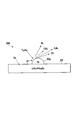
- FIG. 1 is a schematic view showing an exhaust gas purification system according to an embodiment of the present invention.
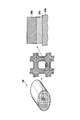
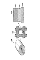
- FIG. 2 is a perspective view and a partially enlarged view showing an example of the HC generation catalyst used for the exhaust gas purification system according to the first embodiment.
- FIG. 3 is an explanatory view showing the mechanism of the oxidative dehydrogenation reaction in the HC generation catalyst.
- FIG. 4 is a perspective view and a partially enlarged view showing an example of the NOx purification catalyst used in the exhaust gas purification system according to the embodiment of the present invention.
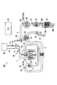
- FIG. 5 is a schematic view showing an example of the configuration of an exhaust gas purification system according to an embodiment of the present invention.
- FIG. 6 is a schematic view showing another example of the configuration of the exhaust gas purification system according to the embodiment of the present invention.
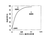
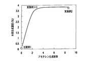
- FIG. 7 is a graph showing the NOx conversion ratio with respect to the amount of acetylene / the total amount of HC in the exhaust gas supplied from the HC generation catalyst to the NOx purification catalyst.
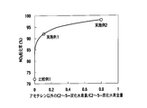
- FIG. 8 is a graph showing the hydrogen generation concentration with respect to the acetylene generation ratio in the HC generation catalyst.
- FIG. 9 is a graph showing the NOx conversion ratio with respect to the amount of acetylene / the total amount of NMHC in the exhaust gas supplied from the HC generation catalyst to the NOx purification catalyst.
- FIG. 10 is a graph showing the NOx conversion ratio with respect to the amount of hydrocarbons having 2-5 carbon atoms in the exhaust gas supplied from the HC generation catalyst to the NOx purification catalyst / the total amount of hydrocarbons.
- FIG. 11 is a graph showing the NOx conversion ratio with respect to the amount of hydrocarbons having 2 to 5 carbons other than acetylene / the total amount of hydrocarbons having 2 to 5 carbons in the exhaust gas supplied from the HC generation catalyst to the NOx purification catalyst It is.
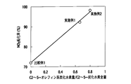
- FIG. 12 is a graph showing the NOx conversion ratio to the amount of olefin hydrocarbon having 2 to 5 carbons / total amount of hydrocarbons having 2 to 5 carbons in the exhaust gas supplied from the HC generation catalyst to the NOx purification catalyst is there.
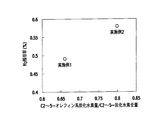
- FIG. 13 shows hydrogen remaining at the outlet of the NOx purification catalyst relative to the amount of olefinic hydrocarbon having 2 to 5 carbons / total amount of hydrocarbons having 2 to 5 carbons in the exhaust gas supplied from the HC generation catalyst to the NOx purification catalyst. It is a graph which shows a rate.
- FIG. 14 is a schematic view showing an example of an HC generator used in the exhaust gas purification system according to the second embodiment.
- FIG. 15 is a perspective view and a partially enlarged view showing an example of the HC generation catalyst used for the exhaust gas purification system according to the third embodiment.
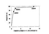
- FIG. 16 is a graph showing the NOx conversion ratio with respect to the amount of aromatic hydrocarbons / the total amount of non-methane hydrocarbons in the exhaust gas supplied from the HC generation catalyst to the NOx purification catalyst.
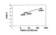
- FIG. 17 is a graph showing the amount of hydrogen (%) with respect to the concentration (ppm) of aromatic hydrocarbons in the exhaust gas supplied from the HC generation catalyst to the NOx purification catalyst.
- FIG. 1 is an explanatory view conceptually showing an exhaust gas purification system according to a first embodiment of the present invention.
- the exhaust gas purification system 100 according to the present embodiment generates an NOx purification catalyst 34 and HC in the flow path 3 of the exhaust gas discharged from the internal combustion engine 1 such as a lean burn engine, direct injection engine and diesel engine.
- Device 33 is arranged.
- the NOx purification catalyst 34 has a function of purifying nitrogen oxides in the exhaust gas.
- the HC generator 33 is provided on the upstream side of the NOx purification catalyst 34, and from hydrocarbons in the exhaust gas discharged from the internal combustion engine 1, acetylene (C 2 H 2 ) and / or carbon number other than acetylene 2 to 5 It has a function of producing 5 (C2-5) hydrocarbons.
- HC generation catalyst 33A which generates acetylene and / or a hydrocarbon having 2 to 5 carbon atoms other than acetylene from hydrocarbons in the exhaust gas.
- the HC generation catalyst 33A is a HC conversion catalyst that converts hydrocarbons in the exhaust gas discharged from the internal combustion engine 1 into lower hydrocarbons having 2 to 5 carbon atoms, and an OSC material having high oxygen storage and release performance. What contains is preferable.
- HC conversion catalysts include platinum (Pt), palladium (Pd), rhodium (Rh) and any mixtures thereof.
- oxides of transition metals specifically, cerium (Ce) and praseodymium (Pr) can be mentioned.
- oxides include cerium dioxide (CeO 2 ) and praseodymium oxide (Pr 6 O 11 ).
- FIG. 2 is a perspective view and a partially enlarged view showing an example of the HC generation catalyst 33A used for the exhaust gas purification system.
- the HC generation catalyst 33A is, for example, one in which HC conversion catalyst layers 33b and 33c are supported on a honeycomb monolith type carrier 33a made of cordierite.
- the HC conversion catalyst layer 33c contains an HC conversion catalyst that converts hydrocarbons in the exhaust gas discharged from the internal combustion engine 1 into lower hydrocarbons by oxidative dehydrogenation reaction, cracking or the like.
- the HC conversion catalyst layer 33 b contains both the HC conversion catalyst and the OSC material.
- the HC generation catalyst 33A is formed by laminating a plurality of layers appropriately selected from a layer containing only the HC conversion catalyst, a layer containing only the OSC material, and a layer containing both the HC conversion catalyst and the OSC material on a honeycomb support. It can be formed. That is, although the catalyst layer has a two-layer structure in FIG. 2, the catalyst layer may be a single layer containing at least one of the HC conversion catalyst and the OSC material, and may be three or more layers.
- the HC conversion catalyst or OSC material is supported on the honeycomb carrier, the HC conversion catalyst Pt, Rh, Pd or other noble metal, or OSC material Ce or Pr on the high specific surface area base material What disperse
- powders such as alumina (Al 2 O 3 ), zirconia (ZrO 2 ) and titania (TiO 2 ) can be used.
- a slurry containing a noble metal element such as Pt, Rh or Pd a slurry containing an oxide containing a transition metal element of Ce or Pr, etc., both the noble metal element and the transition metal element At least one of the slurries containing Next, these slurries can be deposited on a monolithic carrier, and then dried and calcined to form a catalyst layer.
- a noble metal element such as Pt, Rh or Pd
- a slurry containing an oxide containing a transition metal element of Ce or Pr etc.
- the HC conversion catalyst and / or the OSC material may be granulated or pelletized as the HC generation catalyst 33A. Then, the granulated or pelletized HC conversion catalyst and the OSC material may be separately or mixed and filled in a container and disposed in the exhaust gas flow path 3.
- the HC conversion catalyst 33A it is preferable that the HC conversion catalyst intermittently or continuously increases the content of the HC conversion catalyst as it approaches the surface having a large proportion in contact with the exhaust gas. That is, as shown in FIG. 2, it is preferable to increase the content of the HC conversion catalyst as it goes from the honeycomb carrier 33a to the exhaust gas flow path 33d.
- the HC generation catalyst 33A as a method of increasing the content of the HC conversion catalyst closer to the surface 33e, a plurality of slurries different in the content of the noble metal are applied one on another, and the content of the noble metal amount increases the closer to the surface 33e Thus, a method of forming a plurality of catalyst layers can be mentioned.
- the amount of the HC conversion catalyst supported on the HC generation catalyst 33A is preferably 2.8 to 12.0 g / L.
- the HC conversion catalyst amount is 2.8 to 12.0 g / L, the hydrocarbons contained in the exhaust gas are efficiently decomposed into C2 to C5 lower hydrocarbons by the oxidative dehydrogenation reaction and hydrogen (H (H 2 )
- a reducing gas comprising carbon monoxide (CO) can be produced.
- the HC conversion catalyst uses a small amount of oxygen (O 2 ) having an oxygen concentration of about 0.8 to 1.5 vol% in the exhaust gas supplied to the HC generation catalyst 33 A to convert hydrocarbons in the exhaust gas to C 2 to 5
- oxygen and carbon monoxide can be produced together with lower hydrocarbons of
- the HC conversion catalyst is preferably activated at 200 ° C. or higher.
- FIG. 3 shows that acetylene and / or C2-5 lower hydrocarbons are formed from hydrocarbons (eg, decane (C 10 H 22 )) contained in the exhaust gas by the oxidative dehydrogenation reaction of the HC generation catalyst 33A. It is an explanatory view showing a mechanism. As shown in FIG.
- the OSC material 33 f (for example, CeO 2 ) contained in the HC generation catalyst 33 A occludes oxygen in the exhaust gas when the air fuel ratio is lean, and cerium trioxide (Ce 2 O 3) Oxidized to When the air-fuel ratio is stoichiometric or rich, hydrocarbons in the exhaust gas, for example, C 10 H 22 deprive the OSC material (Ce 2 O 3 ) 33 f of oxygen (oxygen ion; O * ).
- CeO 2 cerium trioxide
- C 10 H 22 generates C 2 H 2 and C 2 to 5 lower hydrocarbons (eg, ethylene C 2 H 4 and the like) by the oxidative dehydrogenation reaction by the action of the HC conversion catalyst 33 g, and these lower carbonization Along with hydrogen, a reducing gas containing H 2 and CO is produced. Thereafter, the reduction gas containing H 2 and CO generated by the HC generation catalyst 33 A is supplied to the NOx purification catalyst 34 disposed downstream.
- the technical scope of the present invention is not limited to the embodiment in which the effect is exhibited by the above mechanism.
- C2-5 lower hydrocarbons other than C 2 H 2 produced by the HC generation catalyst 33 A examples include paraffin hydrocarbons (eg, methane, ethane, propane, butane, pentane etc.), olefinic hydrocarbons (eg ethylene, etc.) Propylene, 1-butene, 2-butene, 1-pentene and the like) and acetylenic hydrocarbons (eg propyne, 1-butyne, 2-butyne, 1-pentine and the like) can be mentioned.
- paraffin hydrocarbons eg, methane, ethane, propane, butane, pentane etc.
- olefinic hydrocarbons eg ethylene, etc.
- acetylenic hydrocarbons eg propyne, 1-butyne, 2-butyne, 1-pentine and the like
- the amount of C2 to C5 olefin hydrocarbon having a multiple bond, particularly a double bond is large. Is preferred.
- the amount of acetylene (C 2 H 2 ) generated by the HC generation catalyst 33 A is 0.03 or more in volume ratio to the total amount of hydrocarbons in the exhaust gas supplied to the NOx purification catalyst 34 (C 2 H 2 Preferably the amount / HC total amount 0.03 0.03).
- a necessary and sufficient amount of reducing gas effective for reduction of nitrogen oxides when the amount of C 2 H 2 supplied from the HC generation catalyst 33A to the NOx purification catalyst 34 is 0.03 or more with respect to the total amount of HC in the exhaust gas Can be supplied to the NOx purification catalyst 34. Therefore, the NOx conversion rate for reducing nitrogen oxides to nitrogen can be improved.
- the amount of acetylene supplied from the HC generation catalyst 33A to the NOx purification catalyst 34 is 0.17 or more in volume ratio to the total amount of non-methane hydrocarbons (NMHC) in the exhaust gas supplied to the NOx purification catalyst 34 It is preferable that the amount of C 2 H 2 / the total amount of NMHC ⁇ 0.17). If the amount of C 2 H 2 is 0.17 or more with respect to the total amount of NMHC in exhaust gas excluding methane with low optical activity, sufficient amount necessary for purification of NOx while reducing the amount of NMHC likely to cause photochemical smog A reducing gas containing an amount of reducing agent (H 2 , CO, etc.) can be supplied to the NOx purification catalyst 34.
- H 2 , CO, etc. an amount of reducing agent
- the amount of C2-5 hydrocarbons supplied from the HC generation catalyst 33A to the NOx purification catalyst 34 is 0.1 or more in volume ratio to the total amount of hydrocarbons in the exhaust gas supplied to the NOx purification catalyst 34 (C2- The amount of HC / amount of total HC ⁇ 0.1) of 5 is preferable. Due to the oxidative dehydrogenation reaction in the HC generation catalyst 33A, the larger the amount of C2-5 lower hydrocarbons produced, the greater the amount of hydrogen produced. Therefore, the reduction gas containing a large amount of hydrogen can be supplied to the NOx purification catalyst 34 to improve the NOx purification efficiency.
- the C2-5 lower hydrocarbons other than C 2 H 2 generated by the HC generation catalyst 33 A are decomposed by the partial oxidation reaction or the oxidative dehydrogenation reaction in the NOx purification catalyst 34, and more hydrogen and one monoxide are generated. Carbon is generated. And since these are effectively utilized as a reducing agent, the purification efficiency of nitrogen oxides can be improved. Further, since the lower hydrocarbon of C2-5 has higher reactivity than the hydrocarbon having more than 5 carbon atoms, the lower hydrocarbon of C2-5 itself also acts as a reducing agent in the NOx purification catalyst 34, The purification efficiency of nitrogen oxides can be improved.
- the amount of C2-5 olefinic hydrocarbons produced by the HC generation catalyst is preferably 0.6 or more by volume ratio to the total amount of C2-5 hydrocarbons in the exhaust gas supplied to the NOx purification catalyst C2-5 olefin-based HC content / C2-5 total HC ⁇ 0.6), more preferably a volume ratio of 0.8 or more (C2-5 olefin-based HC content / C2-5 total HC total> 0. 8).
- the inventors of the present invention have found that there is a correlation between the increase in C2-5 lower olefin hydrocarbons produced by the HC generation catalyst and the NOx conversion rate to reduce nitrogen oxides to nitrogen.
- the reason is presumed as follows.
- the amount of reducing agent (H 2 , CO) generated together with the olefinic hydrocarbon in the HC generation catalyst is increased to improve the nitrogen oxide purification efficiency in the NOx purification catalyst.
- the NOx purification catalyst 34 more hydrogen and carbon monoxide are produced from C2 to C5 olefin-based hydrocarbons produced in the HC production catalyst by partial oxidation reaction and oxidative dehydrogenation reaction. . Therefore, since these hydrogen and carbon monoxide are effectively used as a reducing agent, the NOx purification efficiency is improved.
- acetylene content in the exhaust gas supplied to the NOx purifying catalyst 34 a hydrocarbon total amount, non-methane hydrocarbon amount, C2 ⁇ hydrocarbon of 5, C 2 H 2 other than C2 ⁇ 5 hydrocarbon amount and C2 ⁇
- the amount of olefinic hydrocarbon of 5 can be determined by analyzing the above-mentioned exhaust gas with a gas chromatograph mass spectrometer. That is, it can be determined by a gas chromatograph mass spectrometer connected with a thermal conductivity detector (TCD) and / or a flame ionization detector (FID).
- TCD thermal conductivity detector
- FID flame ionization detector
- the peaks of the hydrocarbon are searched for by the mass spectrometer, and the peak areas of the hydrocarbons are compared with each other.
- the relative volume ratio of the above-mentioned hydrocarbons can be determined.
- FIG. 4 is a perspective view and a partially enlarged view showing an example of the NOx purification catalyst 34 used for the exhaust gas purification system.
- the NOx purification catalyst 34 of this example one in which an NOx trapping catalyst layer 34b including an NOx trapping material and a purification catalyst is formed on a honeycomb carrier 34a.
- a zeolite layer 34c is further provided as an HC trap material layer may be used between the NOx trap catalyst layer 34b and the honeycomb carrier 34a.
- the NOx trap material used for the NOx purification catalyst 34 is not particularly limited as long as it can store and desorb nitrogen oxides with the fluctuation of the air fuel ratio of the internal combustion engine.
- NOx trapping materials oxides of alkali metals, alkaline earth metals, and oxides of rare earth elements, such as barium (Ba), magnesium (Mg), sodium (Na), cerium (Ce) and samarium (Sm), etc. A thing can be used suitably.
- the purification catalyst used for the NOx purification catalyst 34 utilizes a small amount of oxygen having an oxygen concentration of about 0.8 to 1.5 vol% in the exhaust gas to produce hydrogen and carbon monoxide together with a lower hydrocarbon of C2 to C5. It is preferable that it is a catalyst which promotes In this case, the lower hydrocarbons are preferably produced by selectively partially oxidizing or oxidatively dehydrogenating hydrocarbons supplied to the NOx purification catalyst 34. Hydrogen, carbon monoxide and lower hydrocarbons are reducing agents for released nitrogen oxides.
- the HC trap material used in the HC trap material layer is not particularly limited as long as it can occlude and desorb hydrocarbons.
- As the HC trapping material at least one of MFI zeolite and ⁇ zeolite having a silica / alumina ratio of 20 or more and less than 60 can be suitably used.
- the NOx purification catalyst 34 for purifying nitrogen oxides is not limited to this example, and an HC trap material, an NOx trap material, and a purification catalyst may be separately and independently disposed in the exhaust gas flow path 3. Further, the HC trap material and the purification catalyst may be combined into one layer, or the HC trap material, the NOx trap material, and the purification catalyst may be combined into one layer. However, in order to fully exhibit the trap function of the NOx trap material, it is preferable to separately install the NOx trap material and the HC trap material, and the HC trap material is disposed on the upstream side of the exhaust gas flow path. Is preferably disposed downstream.
- the HC trap material When the NOx trap material and the HC trap material are laminated on the honeycomb carrier, it is preferable to dispose the HC trap material on the surface layer side and the NOx trap material on the inner layer side closer to the honeycomb carrier. It is preferable to arrange the purification catalyst on the upstream side or the surface side that is most likely to contact the exhaust gas.
- FIG. 5 is a schematic configuration view showing an exhaust gas purification system of a supercharged diesel engine according to the present embodiment.
- the engine main body 1 of the exhaust gas purification system 100 includes a common rail type fuel injection device.
- the common rail type fuel injection device includes a common rail (accumulation chamber) 10 and a fuel injection valve 11 provided for each cylinder.
- the common rail fuel injection system is supplied with fuel from the common rail fuel injection system.
- the common rail fuel injection system includes a fuel supply passage 12 for supplying fuel from the fuel tank 50, a supply pump 13 provided in the fuel supply passage 12, and a return fuel (spill fuel) for returning from the engine body 1 to the fuel tank 50. And a fuel return passage 14.
- the fuel supplied from the fuel tank 50 to the engine body 1 through the fuel supply passage 12 is pressurized by the supply pump 13 and temporarily stored in the common rail 10. Thereafter, the high pressure fuel in the common rail 10 is distributed to the fuel injection valves 11 of the respective cylinders and supplied from the fuel injection valves 11 to the engine body 1.
- the fuel injection valve 11 directly injects fuel into the combustion chamber of the engine body 1 and performs pilot injection, main injection, post injection for injecting fuel under the condition that the fuel is not burned in the cylinder of the engine body 1, etc. Is variably controlled. Further, by changing the fuel pressure in the common rail 10, the fuel injection pressure from the fuel injection valve 11 is variably controlled.
- a portion of the fuel discharged from the supply pump 13 is returned to the fuel supply passage 12 via an overflow passage (not shown) equipped with a one-way valve.
- a pressure control valve (not shown) for changing the flow passage area of the overflow passage is provided. Then, the pressure control valve changes the flow passage area of the overflow passage according to the duty signal from the engine control unit (ECU) 40. Thereby, the substantial fuel discharge amount from the supply pump 13 to the common rail 10 is adjusted, and the fuel pressure in the common rail 10 is controlled.
- the intake passage 2 includes an air cleaner 21 at an upstream position, and an air flow meter 22 that is an intake air amount detector downstream of the air cleaner 21.
- the compressor 31 of the supercharger 30 is provided on the downstream side of the air flow meter 22 of the intake passage 2.
- An intake collector 23 is provided downstream of the compressor 31.
- the exhaust outlet passage 3 a includes an exhaust turbine 32 of the turbocharger 30.
- the supercharger 30 is rotated by the exhaust from the engine body 1 and drives a compressor 31 of the supercharger 30 disposed in the intake passage 2.
- the exhaust outlet passage 3 a includes an EGR passage 4 branched from between the engine body 1 and the exhaust turbine 32 and connected to the intake passage 2.
- the EGR passage 4 is provided with an EGR valve 5.
- the EGR valve 5 is driven to open and close by, for example, a stepping motor type actuator, and can control its opening continuously. In accordance with the opening degree of the EGR valve 5, the amount of exhaust gas recirculated to the intake side, that is, the amount of EGR sucked into the engine body 1 is adjusted.
- the HC generation catalyst 33A is provided on the downstream side of the exhaust turbine 32 of the exhaust gas flow path 3.
- a NOx purification catalyst 34 that occludes and desorbs nitrogen oxides (NOx) in the exhaust gas is provided.
- a diesel particulate filter (DPF) 35 for collecting particulate matter (PM) in the exhaust gas is provided downstream of the catalyst 34.
- air-fuel ratio sensors 36 and 37 which are detectors for detecting the air-fuel ratio (excess air ratio) in the exhaust gas, are provided. .
- the air-fuel ratio sensor 36, 37 includes, for example, an oxygen ion conductive solid electrolyte, which is used to detect the oxygen concentration in the exhaust gas, and the air-fuel ratio (air excess ratio) in the exhaust gas is determined from this oxygen concentration.
- the excess air ratio ( ⁇ ) of the exhaust gas is the value obtained by dividing the air-fuel ratio in the exhaust gas by the theoretical air-fuel ratio (14.7). The larger the value of the air-fuel ratio, the leaner the smaller the excess air ratio. It becomes rich enough.
- the exhaust gas purification system 100 is provided with the air-fuel ratio sensors 36 and 37 and the air flow meter 22 for detecting the amount of intake air. Furthermore, in the exhaust gas purification system 100, as a sensor that detects various states, a rotation speed sensor (not shown) that detects an engine rotation speed, an accelerator opening degree sensor (not shown) that detects an accelerator opening, A water temperature sensor 15 or the like that detects the temperature is provided. Further, the exhaust gas purification system 100 is provided with a pressure sensor 16 and a temperature sensor 17 for detecting the fuel pressure and temperature in the common rail 10 as a sensor for detecting the state of the common rail 10. Furthermore, the DPF 35 is provided with temperature sensors 39a and 39b on the inlet side and the outlet side, and a differential pressure sensor 39c that measures the differential pressure on the inlet side and the outlet side of the DPF 35.
- the amount of hydrocarbons in the exhaust gas may be provided between the HC generation catalyst 33A and the NOx purification catalyst 34.
- the amount of acetylene, the amount of hydrocarbons having 2 to 5 carbon atoms, and the amount of C2 to 5 olefins A sensor or the like that measures the amount of hydrocarbon may be provided.
- a sensor for measuring the amount of hydrogen in the exhaust gas discharged from the NOx purification catalyst 34 may be provided on the downstream side of the NOx purification catalyst 34.
- the engine control unit (ECU) 40 receives signals from various sensors. For example, an air flow meter signal for detecting an intake air amount, a water temperature sensor signal, a signal for a crank angle detection crank angle sensor, a signal for a cylinder discrimination crank angle sensor, a signal for a pressure sensor for detecting fuel pressure in a common rail, fuel temperature Various signals such as a signal of a temperature sensor to be detected, a signal of an accelerator opening degree sensor that detects a depression amount of an accelerator pedal corresponding to a load, and a signal of an air-fuel ratio sensor are input. The ECU 40 determines the fuel injection pressure based on the input detection signals from the various sensors, sets the fuel injection amount and the injection timing, and controls the driving of the fuel injection valve 11.
- an air flow meter signal for detecting an intake air amount For example, an air flow meter signal for detecting an intake air amount, a water temperature sensor signal, a signal for a crank angle detection crank angle sensor, a signal for a cylinder discrimination crank angle sensor,
- the fuel injection valve 11 is an electronic fuel injection valve 11 driven to open and close by an ON-OFF signal from the ECU 40.
- the fuel injection valve 11 injects fuel to the fuel injection chamber by the ON signal and stops the injection by the OFF signal.
- the fuel injection amount is larger.
- the fuel injection timing is appropriately determined by the signal of the crank angle detection crank angle sensor input to the ECU 40, the signal of the cylinder discrimination crank angle sensor, and the like. Then, the fuel injection from the fuel injection valve 11 is executed at an arbitrary injection timing such as pilot injection, main injection and post injection under the control of the ECU 40.
- an apparatus for supplying fuel to exhaust gas in order to generate reducing gas containing hydrogen and carbon monoxide which become the reducing agent of NOx efficiently from exhaust gas with HC generation catalyst is preferred.
- a fuel gas supply apparatus supplied to HC generation catalyst 33A the fuel injection valve 11 controlled by ECU40 grade
- the ECU 40 increases the fuel injection amount injected from the fuel injection valve 11 which is a fuel gas supply device, for example, at the time of execution of the rich spike control. Furthermore, after the main injection which injects the fuel in the vicinity of the piston top dead center of the engine main body 1, the control of implementing the post injection is performed.
- the post injection refers to the injection of fuel at a crank angle that does not burn the fuel in the cylinder of the engine body 1.
- the fuel injection amount and the injection timing of the fuel injected from the fuel injection valve 11 are controlled to increase the fuel injection amount and the post injection is performed, whereby the fuel gas is supplied to the HC generation catalyst 33A. Ru.
- the implementation of the rich spike control is performed by reducing the excess air ratio ⁇ of the exhaust gas from the engine body 1 to 1.0 or less. Specifically, in order to enrich the exhaust gas until the excess air ratio ⁇ becomes 1.0 or less, the control of the ECU 40 is performed to reduce the opening degree of the intake throttle valve 24 and the EGR valve 5. In addition, the injection of fuel from the fuel injection valve 11 is executed at the injection timing of the pilot injection, the main injection, and the post injection, so that the exhaust is enriched.
- the nitrogen oxides stored in the NOx purification catalyst 34 in the lean fuel operating state where the excess air ratio ⁇ is large are detached from the NOx purification catalyst 34 when the rich spike control is performed.
- the oxygen concentration control device Control controls 0.8 to 1.5 vol%.
- the HC generation catalyst 33A in the HC generation catalyst 33A, unburned hydrocarbons in the exhaust gas deprive the OSC material of the HC generation catalyst 33A of oxygen, and the dehydrogenation reaction is facilitated by the action of the HC conversion catalyst. And, along with the formation of hydrocarbons having 2 to 5 carbon atoms other than acetylene (C 2 H 2 ) and / or acetylene, hydrogen is likely to be produced. Therefore, when performing rich spike control, if the oxygen concentration in the exhaust gas is 0.8 to 1.5 vol%, the HC generation catalyst 33A generates a sufficient amount of hydrogen necessary to reduce nitrogen oxides. Can. Further, the reducing gas containing a large amount of hydrogen can be supplied to the NOx purification catalyst 34.
- Examples of the oxygen concentration control device include an intake throttle valve 24 and an EGR valve 5 whose opening degree is controlled by the ECU 40. By controlling the opening degree of the intake throttle valve 24 and the EGR valve 5, the amount of air taken into the engine body 1 can be adjusted, and the oxygen concentration of the exhaust gas supplied to the HC generation catalyst 33A can be controlled.
- An apparatus based on predictive control disclosed in Japanese Patent No. 3918402 is particularly effective as an apparatus for operating the oxygen concentration control apparatus.
- a temperature control device for controlling the temperature of the HC generation catalyst 33A to 200 ° C. or more is provided near the HC generation catalyst 33A.
- the temperature control device is not particularly limited, and examples thereof include a temperature sensor and a heater 38 disposed in the vicinity of the HC generation catalyst 33A.
- control is performed so that the HC generation catalyst 33A becomes 200 ° C. or higher, using the temperature sensor, various heaters, and the like and a device having a CPU and the like as needed.
- the oxygen absorbed in the OSC material of the HC generation catalyst 33A tends to be easily desorbed from the HC generation catalyst 33A by being heated to the desorption temperature, typically 200 to 250 ° C. or higher.
- FIG. 6 is a schematic configuration view showing another example of an exhaust gas purification system of a supercharged diesel engine according to the present embodiment.
- the exhaust gas purification system 110 of this example is provided with a fuel supply system for supplying fuel directly from the fuel tank 50 to the exhaust gas flow path 3 on the upstream side of the HC generation catalyst 33A.
- the fuel supply system includes a second fuel supply passage 6 for supplying fuel directly from the fuel tank 50 to the exhaust gas passage 3 on the upstream side (the inlet side of the HC generation catalyst 33A) of the HC generation catalyst 33A, and a second supply A pump 61 and an injector 62 are provided.
- This fuel supply system is a fuel gas supply device that supplies a fuel gas to the HC generation catalyst 33A.
- fuel is directly injected from the injector 62 to the exhaust gas flow path 3 on the upstream side of the HC generation catalyst 33A through the second supply pump 61 by control of the ECU 40 and the like, for example, at the time of execution of rich spike control.
- the second supply pump 61 adjusts the substantial fuel discharge amount injected from the injector 62 to the exhaust gas flow path 3.
- the fuel gas can be supplied to the HC generation catalyst 33A by injecting the fuel directly from the injector 62 into the exhaust gas flow path 3 on the upstream side of the HC generation catalyst 33A.
- the exhaust gas purification system of the present embodiment can be suitably used as an exhaust gas purification system for a diesel engine that uses, as a fuel, light oil containing a large amount of hydrocarbon having a large carbon number.
- the exhaust gas purification system can be suitably used as an exhaust gas purification system for a lean burn engine and direct injection engine using gasoline as fuel.
- the HC generation catalyst 33A deoxidizes the unburned hydrocarbon in the exhaust gas by the oxygen stored in the OSC material and oxidizes the HC conversion catalyst.
- the reduction gas containing hydrogen (H 2 ) and carbon monoxide (CO) is generated together with the lower hydrocarbon of C 2 to 5 by the chemical dehydrogenation reaction, and is supplied to the NOx purification catalyst 34.
- NOx purification catalyst 34 nitrogen oxide (NOx) from the NOx trapping material is released when the air-fuel ratio is stoichiometric or rich.
- the reduction gas is supplied from the HC generation catalyst 33A, whereby the NOx is efficiently reduced.
- the oxygen concentration control device when the air-fuel ratio is stoichiometric or rich, specifically, when the excess air ratio ⁇ is 1.0 or less, preferably ⁇ is 0.75 to 0.83, the oxygen concentration control device The oxygen concentration in the medium is controlled to 0.8 to 1.5 vol%. At this time, it is preferable to control the oxygen concentration in the exhaust gas to 1.1 to 1.4 vol%, and more preferably to 1.1 to 1.2 vol%.
- the oxygen concentration in the exhaust gas introduced into the HC generation catalyst 33A is as small as 0.8 to 1.5 vol% when the air-fuel ratio is stoichiometric or rich, unburned hydrocarbons in the exhaust gas are stored in the OSC material
- the dehydrogenation reaction tends to generate a reducing gas such as H 2 together with a C 2-5 lower hydrocarbon by oxidative dehydrogenation reaction. Therefore, when the air-fuel ratio is stoichiometric or rich, if the oxygen concentration in the exhaust gas is within the above range, a reducing gas containing hydrogen and the like in an amount sufficient to reduce NOx released from the NOx trapping material is It is easy to supply the NOx purification catalyst 34 from the HC generation catalyst 33A.
- the oxygen stored in the OSC material of the HC generation catalyst 33A is easily desorbed from the OSC material by being heated to the desorption temperature, typically 200 to 250 ° C. or more. Become. If the dehydrogenation reaction or cracking of the hydrocarbon is promoted by the HC generation catalyst 33A when the NOx purification catalyst 34 reduces NOx, the amount of reducing agent such as H 2 supplied to the NOx purification catalyst 34 is The amount can be increased to improve the purification efficiency of NOx. Therefore, it is preferable to set the HC generation catalyst 33A to 200 ° C. or higher when the air-fuel ratio is stoichiometric or rich when NOx is reduced by the NOx purification catalyst 34.
- the HC trap material layer 34c stores the lower hydrocarbons of C2 to C5 supplied from the HC generation catalyst 33A. It can be done. That is, when the air-fuel ratio is lean, the temperature of the NOx purification catalyst 34 itself decreases, so the above-mentioned lower hydrocarbon can be stored in the HC trap material layer 34c. Then, when the air-fuel ratio is stoichiometric or rich, the temperature of the NOx purification catalyst 34 itself rises, so that C2 to C5 lower hydrocarbons stored in the HC trap material layer 34c of the NOx purification catalyst 34 can be released. it can.
- the oxygen concentration control device controls the oxygen concentration in the exhaust gas to 0.8 to 1.5 vol%.
- the lower hydrocarbon released from the HC trap material layer 34c forms a reducing agent such as H 2 by the partial oxidation reaction or the oxidative dehydrogenation reaction in the NOx purification catalyst 34. And the purification efficiency of NOx can be improved.
- the HC generation catalyst 33A that generates acetylene and C2-5 lower hydrocarbons from unburned hydrocarbons in the exhaust gas disposed upstream of the NOx purification catalyst 34
- An HC trap material layer is disposed on the NOx purification catalyst 34.
- the C2 to C5 lower hydrocarbons supplied from the HC generation catalyst 33A can be effectively used to generate a reducing agent such as H 2 and improve the NOx purification efficiency.
- Example 1 ⁇ Production of HC conversion catalyst slurry A>
- the ⁇ -alumina powder was impregnated with an aqueous solution of rhodium nitrate (Rh (NO 3 ) 3 ) having a rhodium concentration of 6%, dried overnight at 120 ° C. to remove water, and calcined at 450 ° C. for 1 hour.
- an HC conversion catalyst powder a having a rhodium loading of 1% was obtained.
- 207 g of this catalyst powder, 603 g of ⁇ -alumina, 90 g of alumina sol, and 900 g of water were put into a magnetic ball mill, mixed and pulverized until the average particle diameter became 3.8 ⁇ m.
- HC conversion catalyst slurry A was obtained.
- Pd (NO 3 ) 3 palladium nitrate
- HC conversion catalyst slurry A was coated on a honeycomb-like monolithic carrier (0.92 L, 400 cpsi) made of cordierite, and the excess slurry attached to the cells was removed by a compressed air flow. Next, the monolithic carrier on which the slurry was attached was dried at 130 ° C. and calcined at 450 ° C. for 1 hour. As a result, an HC conversion catalyst layer A having a coating amount of 100 g / L was formed on the honeycomb carrier.
- the HC conversion catalyst slurry B containing the OSC material was coated on the HC conversion catalyst layer A, and the excess slurry in the cell was removed by a compressed air flow as in the HC conversion catalyst slurry A.
- the monolithic carrier on which the slurry was attached was dried at 130 ° C. and calcined at 450 ° C. for 1 hour.
- an HC conversion catalyst layer B containing an OSC material with a coating amount of 100 g / L was formed on the HC conversion catalyst layer A.
- an HC generation catalyst 1 having an HC conversion catalyst layer A and an HC conversion catalyst layer B containing an OSC material on a honeycomb carrier was obtained.
- the supported amount of rhodium in the HC conversion catalyst layer A supported on the HC generation catalyst 1 is 0.23 g / L, and the supported amount of palladium in the HC conversion catalyst layer B including the OSC material is 2.57 g / L.
- Example 2 ⁇ Production of HC conversion catalyst slurry C>
- the ⁇ -alumina powder was impregnated with an aqueous solution of rhodium nitrate (Rh (NO 3 ) 3 ) having a rhodium concentration of 6%, dried overnight at 120 ° C. to remove water, and calcined at 450 ° C. for 1 hour.
- an HC conversion catalyst powder c having a rhodium loading of 4% was obtained.
- 207 g of this catalyst powder c, 603 g of ⁇ -alumina, 90 g of alumina sol and 900 g of water were put into a magnetic ball mill, mixed and pulverized until the average particle diameter became 3.8 ⁇ m.
- HC conversion catalyst slurry C was obtained.
- Pd (NO 3 ) 3 palladium nitrate
- HC conversion catalyst slurry C was coated on a honeycomb-like monolithic carrier (0.92 L, 400 cpsi) made of cordierite, and the excess slurry attached to the cells was removed by a compressed air flow. Next, the monolithic carrier on which the slurry was attached was dried at 130 ° C. and calcined at 450 ° C. for 1 hour. Thus, an HC conversion catalyst layer C having a coating amount of 100 g / L was formed on the honeycomb carrier.
- an HC conversion catalyst slurry D containing an OSC material was coated on the HC conversion catalyst layer C, and the excess slurry in the cell was removed by a compressed air flow in the same manner as the HC conversion catalyst slurry C.
- the monolithic carrier on which the slurry was attached was dried at 130 ° C. and calcined at 450 ° C. for 1 hour.
- an HC conversion catalyst layer D containing an OSC material with a coating amount of 100 g / L was formed on the HC conversion catalyst layer C.
- an HC generation catalyst 2 having an HC conversion catalyst layer C and an HC conversion catalyst layer D containing an OSC material on a honeycomb carrier was obtained.
- the supported amount of rhodium in the HC conversion catalyst layer C supported on the HC generation catalyst 2 is 0.95 g / L, and the supported amount of palladium in the HC conversion catalyst layer D including the OSC material is 10.3 g / L.
- alumina was introduced into an aqueous solution of zirconium acetate (Zr (CH 3 CO 2 ) 4 ) and stirred at room temperature for about 1 hour.
- this mixture was dried at 120 ° C. overnight to remove moisture, and then fired in air at 900 ° C. for 1 hour to obtain a fired powder.
- the calcined powder was impregnated with an aqueous solution of rhodium nitrate (Rh (NO 3 ) 3 ) having a rhodium concentration of 6%, dried at 120 ° C. overnight, and after removing water, it was calcined at 450 ° C. for 1 hour.
- a catalyst powder f having a rhodium loading of 2% and a zirconium loading of 3% was obtained.
- alumina is put into a mixed aqueous solution of cerium acetate (Ce (CH 3 CO 2 ) 3 ) aqueous solution and barium acetate (Ba (CH 3 CO 2 ) 2 ) aqueous solution and stirred at room temperature for about 1 hour. After drying overnight to remove moisture, the powder was calcined at 600 ° C. for about 1 hour in the atmosphere to obtain a calcined powder.
- a catalyst powder g having a platinum loading of 3.5%, a barium loading of 8% as barium oxide (BaO), and a loading of cerium of 20% as cerium oxide (CeO 2 ) was obtained.
- catalyst powder e 555 g, 25 g of alumina, 230 g of ⁇ -zeolite, 90 g of alumina sol, and 900 g of water were put into a magnetic ball mill, mixed and pulverized until the average particle diameter became 3.2 ⁇ m.
- catalyst slurry E was obtained.
- 317 g of the above catalyst powder, 454 g of catalyst powder, 38 g of alumina, 90 g of alumina sol, and 900 g of water were charged into a magnetic ball mill, mixed and pulverized until the average particle diameter became 3.0 ⁇ m.
- a catalyst slurry F was obtained.
- a zeolite slurry H was coated on a cordierite honeycomb monolith support (1.2 L, 400 cpsi), and the excess slurry attached to the cells was removed by a compressed air flow.
- the monolithic carrier on which the slurry was attached was dried at 130 ° C. and calcined at 450 ° C. for 1 hour.
- a zeolite layer (first layer: HC trap material) with a coating amount of 80 g / L was formed on the honeycomb carrier.
- a catalyst slurry E was coated on the zeolite layer, and the excess slurry in the cell was removed by a flow of compressed air in the same manner as the zeolite slurry H.
- the monolithic carrier on which the slurry was attached was dried at 130 ° C. and calcined at 450 ° C. for 1 hour.
- a catalyst layer with a coat amount of 220 g / L (second layer: coexistence layer of HC trap material and NOx trap catalyst) was formed.
- a catalyst slurry F was coated on the catalyst layer, and the excess slurry in the cell was removed by a compressed air flow as in the catalyst slurry E.
- the monolithic carrier on which the slurry was attached was dried at 130 ° C. and calcined at 450 ° C. for 1 hour.
- a catalyst layer (third layer: NOx trap catalyst layer) with a coating amount of 100 g / L was formed on the catalyst layer (second layer).
- HC-generating catalyst 33A (HC-generating catalyst 1 of Example 1 or HC-generating catalyst of Example 2) on the upstream side of the exhaust gas flow path 3 of a 4-cylinder 2500 cc direct injection diesel engine manufactured by Nissan Motor Co., Ltd. 2) attached, and the exhaust gas purification system was formed. Further, the NOx purification catalyst 34 was mounted downstream of the HC generation catalyst 33A. Further, as Comparative Example 1, only the NOx purification catalyst 34 was attached to the exhaust gas flow path 3 without attaching the HC generation catalyst 33A, thereby forming an exhaust gas purification system.
- the hydrogen generation concentration relative to the acetylene generation ratio in the HC generation catalyst was determined by a gas chromatograph mass spectrometer. The results are shown in FIG.
- the amount of acetylene relative to the total amount of non-methane hydrocarbons in the exhaust gas supplied from the HC generation catalyst 33A to the NOx purification catalyst 34 was determined in the same manner as the method described above. The results are shown in FIG.
- the oxygen concentration in the exhaust gas at the rich spike time was controlled to 0.8 to 1.2 vol% according to the method disclosed in Japanese Patent No. 3918402.
- the fuel used is a commercially available JIS No. 2 light oil, and the inlet temperature of the HC generation catalyst 33A was set at 220 ° C.
- the conversion rate (reduction rate) of NOx in the NOx purification catalyst is higher as the ratio of the amount of acetylene supplied from the HC generation catalyst to the NOx purification catalyst is higher. .
- 90% or more when the amount of acetylene supplied from the HC generation catalyst 33A is 0.025 or more (C 2 H 2 amount / HC total amount 0.02 0.025) with respect to the total amount of hydrocarbons contained in the exhaust gas High NOx conversion was obtained.
- the amount of acetylene supplied from the HC generation catalyst to the NOx purification catalyst is 0.17 or more (C 2 H 2 amount / N MHC total amount 00) with respect to the total amount of non-methane hydrocarbons in the exhaust gas. .17), a high NOx conversion of 90% or more to 95% or more was obtained.
- ⁇ Performance test II> In the same manner as in the performance test I, the amount of C2-5 hydrocarbons relative to the total amount of hydrocarbons in the exhaust gas supplied from the HC generation catalyst 33A to the NOx purification catalyst 34 by the above exhaust gas purification system is a gas chromatograph mass spectrometer It measured by. Further, the NOx conversion rate of the NOx purification catalyst 34 in the rich section was determined by measuring the NOx concentration before and after the catalyst 34 using a chemiluminescence method NOx analyzer. The results are shown in FIG.
- the NOx conversion ratio of the NOx purification catalyst is higher as the ratio of the amount of C2 to C5 hydrocarbons supplied from the HC generation catalyst to the NOx purification catalyst is higher.
- the amount of C2-5 hydrocarbons supplied from the HC generation catalyst relative to the total amount of hydrocarbons contained in the exhaust gas is at least 0.1 (HC amount of C2-5 / HC total amount 0.1 0.1), A high NOx conversion of 90% or more was obtained preferably at 0.12 or more.
- hydrocarbons the total amount of C2 ⁇ 5 in the exhaust gas hydrocarbons of acetylene other C2 ⁇ 5 supplied from the HC generation catalyst is 0.05 or more (C 2 H 2 other than C2 ⁇ 5 HC When the amount / the total amount of HC of C2 to 5 ⁇ 0.05), more preferably 0.1 or more, high NOx conversion of 90% or more was obtained.
- the NOx conversion rate of the NOx purification catalyst is the amount of C2-5 olefin hydrocarbon supplied from the HC generation catalyst to the NOx purification catalyst, and the NOx conversion rate of reducing nitrogen oxides to nitrogen, was found to be correlated.
- the amount of C2 to C5 olefinic hydrocarbons is 0.6 or more (C2 to C5 olefinic hydrocarbons / When the total amount of HC of C2-5 is 0.60.6), a high NOx conversion of 90% or more was obtained.
- the exhaust gas purification system of the present embodiment will be described in detail based on the drawings.
- the NOx purification catalyst 34 is disposed downstream of the exhaust gas flow path 3 of the internal combustion engine 1 as in the first embodiment, and the HC generator is upstream 33 are arranged.
- the NOx purification catalyst 34 has a function of absorbing and desorbing nitrogen oxides (NOx) in the exhaust gas and purifying the same, as in the first embodiment.
- HC generator 33 used in the system of this embodiment like the first embodiment, acetylene (C 2 H 2) from the hydrocarbons in the exhaust gas discharged from the internal combustion engine 1 and / or carbon other than acetylene It has a function to generate several to five (C2 to 5) hydrocarbons.
- the HC generation catalyst 33A containing an HC conversion catalyst is used as the HC generator 33, but in the present embodiment, the HC generator 33B described below is used.
- the HC generator 33 B supplies a supply pipe 71 for supplying at least a part of the exhaust gas discharged from the internal combustion engine 1 to the reaction vessel 70, and a fuel injection for supplying fuel gas to the reaction vessel 70.
- a device 72 and a spark plug 73 having an electrode for discharging the mixture of the exhaust gas and the fuel gas for spark ignition are provided.
- the HC generator 33B is a discharger for rectifying the flow of the generated acetylene and / or hydrocarbon having 2 to 5 carbon atoms other than acetylene, and the exhaust gas for supplying the generated acetylene and the like to the NOx purification catalyst 34 And a tube 75.
- the HC generator 33B can be replaced with the HC generation catalyst 33A in the exhaust gas purification system shown in FIG. Therefore, as the fuel injection device 72, the second fuel supply passage 6, the second supply pump 61 and the injector 62 shown in FIG. 6 can be used.
- hydrocarbons having 2 to 5 carbon atoms other than acetylene and / or acetylene are produced by the following method using the HC generator 33B.
- the exhaust gas discharged from the internal combustion engine 1 is supplied to the reaction container 70 through the supply pipe 71, and the fuel gas is further supplied through the fuel injection device 72.
- the exhaust gas and the fuel gas are mixed so that the excess air ratio ( ⁇ ) in the mixed gas of the exhaust gas and the fuel gas is 0.9 or less, and the oxygen concentration in the mixed gas is 0.8 to 1.5 vol%. adjust.
- the oxygen concentration can be adjusted within the above range by controlling the opening degree of the intake air throttle valve 24 and the EGR valve 5 as described in the first embodiment. Further, the excess air ratio ( ⁇ ) can be adjusted within the above range by controlling the injection amount of fuel from the fuel injection device 72.
- the HC generator 33B is used instead of the HC generation catalyst 33A. Therefore, the necessary amount of acetylene and / or hydrocarbon having 2 to 5 carbon atoms other than acetylene can be supplied to the NOx purification catalyst 34 when necessary. That is, since the NOx purification catalyst 34 can occlude a fixed amount of NOx, when the NOx storage amount is saturated, the HC generator 33 B is used to supply acetylene etc. while the air fuel ratio is stoichiometrically controlled by the internal combustion engine. Alternatively, by enriching, nitrogen oxides (NOx) from the NOx trap material can be released, and the reduction gas can reduce NOx efficiently.
- NOx nitrogen oxides
- the HC generator 33 B shown in FIG. 14 supplies at least a part of the exhaust gas discharged from the internal combustion engine 1 to the reaction container 70 through the supply pipe 71.
- air may be supplied to the reaction vessel 70 from the outside through the supply pipe 71 instead of the exhaust gas.
- unburned hydrocarbons remain in the exhaust gas, but no hydrocarbons remain in the air. Therefore, in order to make the excess air ratio ( ⁇ ) in the mixed gas be 0.9 or less, it is necessary to supply a slightly more fuel gas.
- the amount of acetylene generated by the HC generator 33B is 0.03 or more in volume ratio with respect to the total amount of hydrocarbons in the exhaust gas supplied to the NOx purification catalyst 34. Is preferred.
- the amount of acetylene supplied from the HC generator 33B to the NOx purification catalyst 34 is 0.17 or more in volume ratio with respect to the total amount of non-methane hydrocarbons in the exhaust gas supplied to the NOx purification catalyst 34 preferable.
- the amount of C2-5 hydrocarbons supplied from the HC generator 33B to the NOx purification catalyst 34 is 0.1 or more in volume ratio with respect to the total amount of hydrocarbons in the exhaust gas supplied to the NOx purification catalyst 34
- the amount of HC of C2-5 / the total amount of HC ⁇ 0.1) is preferable.
- the volume ratio is preferably 0.05 or more.
- the amount of C2-5 olefinic hydrocarbons produced by the HC generation catalyst is preferably 0.6 in volume ratio to the total amount of C2-5 hydrocarbons in the exhaust gas supplied to the NOx purification catalyst.
- the above, more preferably, the volume ratio is 0.8 or more.
- paraffin hydrocarbons eg, methane, ethane, propane, butane, pentane etc.
- Olefin-based hydrocarbons eg, ethylene, propylene, 1-butene, 2-butene, 1-pentene and the like
- acetylene-based hydrocarbons eg, propyne, 1-butyne, 2-butyne, 1-pentine and the like
- acetylene or generated by HC generator 33B of lower hydrocarbons of C 2 H 2 other than C2 ⁇ 5, multiple bonds, of C2 ⁇ 5 in particular having a double bond It is preferred that the amount of olefinic hydrocarbon is large.
- the NOx purification catalyst 34 is disposed downstream of the exhaust gas flow path 3 of the internal combustion engine 1 as in the first embodiment, and the HC generator is upstream 133 are arranged.
- the NOx purification catalyst 34 has a function of absorbing and desorbing nitrogen oxides (NOx) in the exhaust gas and purifying the same, as in the first embodiment.
- HC generator 133 used for a system of this embodiment has a function to generate aromatic hydrocarbon from hydrocarbon in exhaust gas.
- FIG. 15 is a perspective view and a partially enlarged view showing an example of the HC generation catalyst 133A used in the exhaust gas purification system of the present embodiment.
- the HC generation catalyst 133A is obtained by, for example, supporting a catalyst layer 133c containing the HC conversion catalyst and a catalyst layer 133b containing both the HC conversion catalyst and the OSC material on a honeycomb monolith type carrier 133a made of cordierite etc. It is.
- the HC generation catalyst 133A is an HC conversion catalyst that converts paraffin hydrocarbons having 6 or more carbon atoms (C6 or more) and olefin hydrocarbons having 6 or more carbon atoms in the exhaust gas into aromatic hydrocarbons, and oxygen
- the material preferably contains an OSC material having high storage and release performance.
- the HC conversion catalyst is preferably one containing at least one noble metal element selected from the group consisting of platinum (Pt), rhodium (Rh) and palladium (Pd).
- the OSC material may, for example, be a transition metal element, specifically an oxide containing at least one transition metal element selected from the group consisting of cerium (Ce) and praseodymium (Pr). Examples of such oxides include cerium dioxide (CeO 2 ) and praseodymium oxide (Pr 6 O 11 ).
- the amount of HC conversion catalyst supported on the HC generation catalyst 133A specifically, the amount of noble metal such as Pt, Rh or Pd is preferably 2.8 to 12.0 g / L.
- the supported amount of the noble metal element supported on the HC generation catalyst 133A is 2.8 to 12.0 g / L, C6 or more paraffin hydrocarbon and / or C6 or more olefin contained in the exhaust gas by dehydrogenation reaction Based hydrocarbons can be efficiently converted to aromatic hydrocarbons. Furthermore, a reducing gas containing a large amount of hydrogen can be generated by the dehydrogenation reaction of the above-mentioned hydrocarbon.
- the HC conversion catalyst converts the unburned hydrocarbon in the exhaust gas into an aromatic hydrocarbon by using a small amount of oxygen with an oxygen concentration of 0.8 to 1.5 vol% in the exhaust gas supplied to the HC generation catalyst 133A. It is preferable to be able to generate hydrogen by dehydrogenation reaction while converting.
- the HC conversion catalyst is preferably activated at 200 ° C. or higher.
- the HC conversion catalyst intermittently or continuously increases the content of the noble metal element constituting the HC conversion catalyst as it approaches the surface having a large proportion in contact with the exhaust gas. That is, as shown in FIG. 15, it is preferable to increase the content of the HC conversion catalyst as going from the honeycomb carrier 133a to the exhaust gas flow path 133d.
- the HC generation catalyst 133A as a method of increasing the content of the HC conversion catalyst closer to the surface 133e, a plurality of slurries differing in the content of the noble metal are applied one on another, and the content of the noble metal amount increases the closer to the surface 133e Thus, a method of forming a plurality of catalyst layers can be mentioned.
- the HC generation catalyst 133A contains both the noble metal element constituting the HC conversion catalyst and the transition metal element constituting the OSC material in the same catalyst layer.
- both the noble metal element and the transition metal element are contained in the same catalyst layer in the HC generation catalyst 133A, for example, unburned hydrocarbon such as C6 or more paraffin hydrocarbon at the time of execution of rich spike control. Deprives the oxygen stored in the OSC material.
- unburned hydrocarbons are easily converted to aromatic hydrocarbons, and hydrogen is also easily generated at the same time. That is, it is preferable to include both the HC conversion catalyst and the OSC material in the same catalyst layer, since dehydrogenation reaction to generate aromatic hydrocarbon and hydrogen is likely to occur.
- the HC generation catalyst 133A is not only a catalyst layer containing both the HC conversion catalyst and the OSC material, but a catalyst layer containing only the HC conversion catalyst and a catalyst layer containing only the OSC material are appropriately selected on the honeycomb support. It can be formed. That is, although the catalyst layer has a two-layer structure in FIG. 15, the catalyst layer may be a single layer containing at least one of the HC conversion catalyst and the OSC material, and may be three or more layers.
- distributed the oxide etc. can be used.
- powders such as alumina (Al 2 O 3 ), zirconia (ZrO 2 ) and titania (TiO 2 ) can be used.
- a slurry containing a noble metal element such as Pt, Rh or Pd a slurry containing an oxide containing a transition metal element of Ce or Pr, etc., both the noble metal element and the transition metal element At least one of the slurries containing Next, these slurries can be deposited on a monolithic carrier, and then dried and calcined to form a catalyst layer.
- a noble metal element such as Pt, Rh or Pd
- a slurry containing an oxide containing a transition metal element of Ce or Pr etc.
- the HC conversion catalyst and / or the OSC material may be granulated or pelletized as the HC generation catalyst 133A. Then, the granulated or pelletized HC conversion catalyst and the OSC material may be separately or mixed and filled in a container and disposed in the exhaust gas flow path 3.
- the amount of aromatic hydrocarbons produced by the HC generation catalyst 133A is 0.02 or more in volume ratio to the total amount of non-methane hydrocarbons (NMHC) in the exhaust gas supplied to the NOx purification catalyst 34 (aroma Preferably, the group HC amount / NMHC total amount 0.02 0.02).
- NMHC non-methane hydrocarbons
- the amount of aromatic hydrocarbons in the exhaust gas supplied from the HC generation catalyst 133A to the NOx purification catalyst 34 is 0.02 or more with respect to the total amount of NMHC in the exhaust gas, nitrogen oxides are formed together with the formation of aromatic hydrocarbons.
- the HC generation catalyst 133A can supply a reduction gas containing a necessary and sufficient amount of hydrogen effective for reduction of nitrogen oxides to the NOx purification catalyst 34. Therefore, the NOx conversion rate for reducing nitrogen oxides to nitrogen can be improved.
- the amount of aromatic hydrocarbon supplied to the NOx purification catalyst 34 is 0.02 or more with respect to the total amount of NMHC in the exhaust gas, the amount of NMHC that is likely to cause photochemical smog is reduced to purify NOx.
- a reducing gas can be produced that contains the necessary sufficient amount of reducing agent (H 2 ).
- the amount of aromatic hydrocarbon and the amount of non-methane hydrocarbon in the exhaust gas supplied to the NOx purification catalyst 34 can be determined by analyzing the above-mentioned exhaust gas with a gas chromatograph mass spectrometer as described above.
- the NOx purification catalyst 34 described in the first embodiment can be used as the NOx purification catalyst disposed downstream of the HC generation catalyst 133A.
- the system of FIG.5 and FIG.6 detailed in 1st embodiment can be used as an exhaust gas purification system.
- the exhaust gas purification system of the present embodiment supplies, to the HC generation catalyst 133A, a gas containing a large amount of paraffin hydrocarbons of C6 or more and / or olefin hydrocarbons of C6 or more at the time of execution of rich spike control. Is preferred. That is, it is preferable to supply a gas containing a paraffin hydrocarbon of C6 or more and / or an olefin hydrocarbon of C6 or more to the HC generation catalyst 133A by using the fuel gas supply device.
- the gas containing the paraffin hydrocarbon of C6 or more and / or the olefin hydrocarbon of C6 or more is supplied to the HC generation catalyst 133A by the fuel gas supply device during execution of the rich spike control, the HC generation catalyst 133A Then, aromatic hydrocarbons are produced from HCs of C6 or more. Furthermore, dehydrogenation reaction accompanying this formation produces hydrogen which is a reducing agent. As described above, when the reduction gas containing a large amount of hydrogen as the reducing agent is generated by the HC generation catalyst 133A during the rich spike control, the reduction gas is supplied to the NOx purification catalyst 34. The NOx conversion rate (reduction rate) of desorbed nitrogen oxides can be increased.
- the exhaust gas purification system preferably supplies a gas containing a large amount of C6 or more paraffin hydrocarbon and / or C6 or more olefin hydrocarbon to the HC generation catalyst 133A. Therefore, the above-mentioned exhaust gas purification system can be suitably used as an exhaust gas purification system of a diesel engine using as a fuel a light oil containing a large amount of hydrocarbon having a large carbon number.
- Example 3 the HC generation catalyst 1 and the NOx purification catalyst of Example 1 were used. Furthermore, in Example 4, the HC generation catalyst 2 and the NOx purification catalyst of Example 2 were used. Furthermore, as shown in FIG. 6, an HC-generating catalyst 133A (HC-generating catalyst 1 of Example 3 or Example 4 of Example 3) was installed on the upstream side of the exhaust gas flow path 3 of the in-line four-cylinder 2500 cc direct injection diesel engine 1 manufactured by Nissan Motor. The HC generation catalyst 2) was attached to form an exhaust gas purification system. Further, the NOx purification catalyst 34 was mounted downstream of the HC generation catalyst 133A. Further, as Comparative Example 2, only the NOx purification catalyst 34 was attached to the exhaust gas flow path 3 without attaching the HC generation catalyst 133A, thereby forming an exhaust gas purification system.
- the excess air ratio ⁇ of the exhaust gas during the rich spike control was controlled to 1.0 or less, and the oxygen concentration of the exhaust was controlled to 0.8 to 1.2 vol% according to the method disclosed in Japanese Patent No. 3918402.
- the fuel used is a commercially available JIS No. 2 gas oil, and the inlet temperature of the HC generation catalyst 133A was set to 220 ° C.
- the amount of aromatic hydrocarbon relative to the total amount of NMHC in the exhaust gas supplied from the HC generation catalyst 133A to the NOx purification catalyst 34 was measured by a gas chromatograph mass spectrometer.
- the NOx conversion rate of the NOx purification catalyst 34 was determined by measuring the NOx concentration before and after the catalyst 34 using a chemiluminescence NOx analyzer. The results are shown in FIG.
- the concentration (ppm) of the aromatic hydrocarbon in the exhaust gas supplied from the HC generation catalyst 133A to the NOx purification catalyst 34 at the time of execution of the rich spike control, and the hydrogen amount (%) with respect to the total exhaust gas in the same exhaust gas was measured by a gas chromatograph mass spectrometer. The results are shown in FIG.
- the concentration (ppm) of the aromatic hydrocarbon in the exhaust gas indicates the volume ratio of the aromatic hydrocarbon in the exhaust gas, and the amount of hydrogen (%) to the total amount of the exhaust gas also indicates the volume ratio of hydrogen in the exhaust gas.
- the conversion rate of NOx in the NOx purification catalyst is higher as the ratio of the amount of aromatic hydrocarbon in the exhaust gas supplied from the HC generation catalyst to the NOx purification catalyst is higher. did it.
- the amount of aromatic hydrocarbon is 2.0% or more (aromatic HC amount / HC total amount 0.02 0.02) with respect to the total amount of NMHC contained in the exhaust gas, a high NOx conversion ratio of 90% or more is obtained It was done.
- the conversion rate of NOx was less than 80%.
- the present invention is an HC generator that generates acetylene and / or hydrocarbons having 2 to 5 carbon atoms other than acetylene from hydrocarbons in exhaust gas upstream of a NOx purification catalyst that occludes and desorbs NOx in exhaust gas. Place.
- hydrogen, carbon monoxide, etc. are mixed with hydrocarbons having 2 to 5 carbon atoms other than acetylene and / or acetylene from unburned hydrocarbons in exhaust gas by oxidative dehydrogenation reaction.
- the NOx purification efficiency can be improved by sufficiently supplying a reducing gas containing a large amount of hydrogen or the like to be the reducing agent to the NOx purification catalyst.
- an HC generator that generates aromatic hydrocarbons from hydrocarbons in the exhaust gas is disposed upstream of the NOx purification catalyst. Then, a gas containing an olefinic hydrocarbon having 6 or more carbon atoms and / or a paraffinic hydrocarbon having 6 or more carbon atoms is supplied to the HC generator. Thereby, in the HC generator, hydrogen is produced together with the aromatic hydrocarbon by the dehydrogenation reaction.
- the NOx purification efficiency can be improved by sufficiently supplying a reducing gas containing a large amount of hydrogen or the like to be the reducing agent to the NOx purification catalyst.
Abstract
排ガス浄化システム(100)は、排ガス流路(3)に配置した窒素酸化物を浄化するNOx浄化触媒(34)と、前記NOx浄化触媒(34)の上流側の前記排ガス流路(3)に配置し、排ガス中の炭化水素から、アセチレン、アセチレン以外の炭素数が2~5の炭化水素及び芳香族炭化水素の少なくとも一つを生成するHC生成器(33,133)と、を備える。さらに、前記排ガス浄化システムを用いた排ガス浄化方法は、前記システム(100)において、空燃比が理論空燃比又はリッチのときに、前記HC生成触媒(33A,133A)に供給する排ガス中の酸素濃度を0.8~1.5vol%にする。
Description
本発明は、内燃機関からの排ガスを有効に浄化できる排ガス浄化システム及びこれを用いた排ガス浄化方法に関する。
近年、地球環境に対する配慮から、二酸化炭素(CO2)排出量の低減が叫ばれており、自動車の内燃機関の燃費向上を目的に希薄燃焼化が図られている。希薄燃焼するエンジンとしては、ガソリンのリーンバーンエンジン、直噴エンジン及びディーゼルエンジンなどがある。しかし、このようなエンジンからの排ガスには酸素が多く含まれており、従来の三元触媒では窒素酸化物(NOx)を効率よく還元浄化することができない。そのため、従来より、このような排ガスを効率良く浄化するための種々の技術開発が進められている。
上記排ガスを浄化する有効な方法の一つは、NOxトラップ触媒を使用することである。このNOxトラップ触媒は、空燃比がリーンの時には排ガス中のNOxを酸化してトラップし、空燃比が理論空燃比又はリッチの時にはトラップしたNOxを放出して窒素(N2)に還元する。このとき、排ガス中の還元剤(水素(H2)、一酸化炭素(CO)、炭化水素(HC))を増加させることにより、NOxを還元している。しかし、余剰の還元剤、特に余剰の炭化水素が、NOx還元に使われずに放出され、これが酸素と反応してCO2の排出量を増加させる要因となる場合がある。また、上記排ガス中の還元剤を増加すべく、排ガスの空燃比を急激に理論空燃比又はリッチにすることは、運転性や燃費の悪化を起こすために好ましくない。
そこで、NOx還元に対して、より有効な還元剤、特に水素を使用する試みがなされている。そして、従来、水蒸気改質により水素を生成する触媒が提案されている(例えば、特許文献1参照)。
しかしながら、水蒸気改質反応は吸熱反応であり、十分な反応速度を得るために熱量の供給、即ち高温条件の供給が必要になる。そのため、例えば、運転負荷が低い場合のように、実際の運転モードの条件下では、NOx浄化効果が得られるような十分な水素が供給されていると言い難い。また、NOx転化率(還元率)を高めるために空燃比をリッチにすると、未反応の炭化水素の排出量が増加して環境悪化の要因になるため、当該炭化水素を除去するための触媒を追加する必要があった。
このように、従来の方法では、NOxの浄化効率を向上させるために、十分な水素や一酸化炭素等を含む還元ガスが触媒に供給されているとは言い難い。また、供給された還元ガスが、窒素酸化物の浄化効率を向上させるように有効に利用されているとは言えない状態であった。
本発明は、このような従来技術の有する課題に鑑みてなされたものである。そして、その目的は、排ガス中の未燃の炭化水素から水素等の還元ガスを生成し、この還元ガスを有効に利用して、窒素酸化物の浄化効率を向上させる排ガス浄化システム及びこれを用いた排ガス浄化方法を提供することにある。
本発明の第一の態様に係る排ガス浄化システムは、排ガス流路に配置した窒素酸化物を浄化するNOx浄化触媒と、上記NOx浄化触媒の上流側の上記排ガス流路に配置し、排ガス中の炭化水素から、アセチレン、アセチレン以外の炭素数が2~5の炭化水素及び芳香族炭化水素の少なくとも一つを生成するHC生成器と、を備えたことを特徴とする。
本発明の第二の態様に係る排ガス浄化方法は、排ガス流路に配置した窒素酸化物を浄化するNOx浄化触媒と、上記NOx浄化触媒の上流側の上記排ガス流路に配置し、排ガス中の炭化水素からアセチレン、アセチレン以外の炭素数が2~5の炭化水素及び芳香族炭化水素の少なくとも一つを生成するHC生成触媒と、を備えた排ガス浄化システムを準備する工程と、空燃比が理論空燃比又はリッチのときに、上記HC生成触媒に供給する排ガス中の酸素濃度を0.8~1.5vol%にする工程と、を有することを特徴とする。
以下、本発明の排ガス浄化システム及び排ガス浄化方法について、図面に基づき詳細に説明する。なお、本明細書において、濃度、含有量及び配合量などのついての「%」は、特記しない限り質量百分率を表すものとする。
[第一実施形態]
(排ガス浄化システム)
図1は、本発明の第一実施形態に係る排ガス浄化システムを概念的に示す説明図である。図1に示すように、本実施形態の排ガス浄化システム100は、リーンバーンエンジン、直噴エンジン及びディーゼルエンジン等の内燃機関1から排出される排ガスの流路3に、NOx浄化触媒34及びHC生成器33を配置したものである。上記NOx浄化触媒34は、排ガス中の窒素酸化物を浄化する機能を有する。そして、上記HC生成器33は、NOx浄化触媒34の上流側に設けられ、内燃機関1から排出された排ガス中の炭化水素からアセチレン(C2H2)及び/又はアセチレン以外の炭素数2~5(C2~5)の炭化水素を生成する機能を有する。
上記HC生成器33としては、排ガス中の炭化水素からアセチレン及び/又はアセチレン以外の炭素数2~5の炭化水素を生成するHC生成触媒33Aを使用することができる。HC生成触媒33Aは、内燃機関1から排出される排ガス中の炭化水素を、炭素数が2~5の低級炭化水素に変換するHC変換触媒と、酸素の吸蔵放出性能の高いOSC材と、を含有するものが好ましい。HC変換触媒としては、白金(Pt)、パラジウム(Pd)、ロジウム(Rh)及びこれらの任意の混合物が挙げられる。また、OSC材としては、遷移金属、具体的にはセリウム(Ce)及びプラセオジム(Pr)の酸化物等が挙げられる。このような酸化物としては、二酸化セリウム(CeO2)や酸化プラセオジム(Pr6O11)等が挙げられる。
図2は、排ガス浄化システムに用いるHC生成触媒33Aの一例を示す斜視図及び部分拡大図である。HC生成触媒33Aは、例えばコーディエライト製のハニカム状のモノリス型担体33aに、HC変換触媒層33b及び33cを担持させたものをである。上記HC変換触媒層33cは、内燃機関1から排出される排ガス中の炭化水素を酸化的脱水素反応又はクラッキング等によって、低級炭化水素に変換するHC変換触媒を含有する。さらに、上記HC変換触媒層33bは、上記HC変換触媒及びOSC材の両方を含有している。
HC生成触媒33Aは、ハニカム担体上に、HC変換触媒のみを含む層、OSC材のみを含む層、HC変換触媒及びOSC材の両方を含む層の中から適宜選択した複数の層を積層して形成することができる。つまり、図2では触媒層が二層構造となっているが、触媒層はHC変換触媒及びOSC材の少なくとも一方を含有する単層であっても良く、さらに三層以上であっても良い。なお、ハニカム担体上にHC変換触媒やOSC材を担持させる際には、高比表面積基材上に、HC変換触媒であるPt、Rh及びPd等の貴金属や、OSC材であるCe及びPrの酸化物等を分散させたものを用いることができる。高比表面積基材としては、アルミナ(Al2O3)、ジルコニア(ZrO2)及びチタニア(TiO2)等の粉末を用いることができる。
また、触媒層の形成方法としては、まず、Pt、Rh又はPd等の貴金属元素を含むスラリ、Ce又はPrの遷移金属元素を含む酸化物等を含むスラリ、上記貴金属元素及び遷移金属元素の両者を含むスラリの少なくとも一つを調製する。次に、これらのスラリを、モノリス担体上に付着させ、その後乾燥及び焼成することにより、触媒層を形成することができる。
また、HC生成触媒33Aとして、HC変換触媒及び/又はOSC材を粒状化又はペレット化しても良い。そして、粒状化又はペレット化したHC変換触媒及びOSC材を各々別個に、又は、混合して容器に充填し、排ガス流路3に配置しても良い。
HC生成触媒33Aにおいて、HC変換触媒は、排ガスと接触する割合の大きい表面に近いほど、断続的又は連続的にHC変換触媒の含有量を増大させたものが好ましい。つまり、図2に示すように、ハニカム担体33aから排ガス流路33dに向かうにつれ、HC変換触媒の含有量を増大させたものが好ましい。HC生成触媒33Aにおいて、表面33eに近いほどHC変換触媒の含有量を増大させる方法としては、貴金属の含有量が異なるスラリを複数塗り重ねて、表面33eに近いほど貴金属量の含有量が多くなるように、複数の触媒層を形成する方法が挙げられる。
HC生成触媒33Aに担持させるHC変換触媒の量、具体的にはPt、Rh又はPd等の貴金属量は2.8~12.0g/Lであることが好ましい。HC変換触媒量が2.8~12.0g/Lであると、酸化的脱水素反応により排ガス中に含まれる炭化水素を効率的にC2~5の低級炭化水素に分解すると共に、水素(H2)及び一酸化炭素(CO)を含む還元ガスを生成することができる。
HC変換触媒は、HC生成触媒33Aに供給される排ガス中の酸素濃度が0.8~1.5vol%程度の少量の酸素(O2)を活用して、排ガス中の炭化水素からC2~5の低級炭化水素と共に、水素や一酸化炭素を生成できるものが好ましい。また、HC変換触媒は、200℃以上で活性化するものでが好ましい。
図3は、HC生成触媒33Aの酸化的脱水素反応によって、排ガス中に含まれる炭化水素(例えば、デカン(C10H22))からアセチレン及び/又はC2~5の低級炭化水素が生成されるメカニズムを示す説明図である。図3に示すように、HC生成触媒33Aに含まれるOSC材33f(例えば、CeO2)は、空燃比がリーンであるときに排ガス中の酸素を吸蔵し、三酸化二セリウム(Ce2O3)に酸化される。空燃比がストイキ又はリッチの時に、排ガス中の炭化水素、例えばC10H22が、OSC材(Ce2O3)33fから酸素(酸素イオン;O*)を奪う。そして、HC変換触媒33gの作用による酸化的脱水素反応により、C10H22からC2H2やC2~5の低級炭化水素(例えばエチレンC2H4等)を生成し、これらの低級炭化水素と共に、H2やCOを含む還元ガスを生成する。その後、HC生成触媒33Aで生成されたH2やCOを含む還元ガスが、下流側に配置されたNOx浄化触媒34に供給される。なお、本発明の技術的範囲が上記メカニズムによって効果が発現する実施態様に限定されるわけではない。
HC生成触媒33Aで生成されるC2H2以外のC2~5の低級炭化水素としては、パラフィン系炭化水素(例えばメタン、エタン、プロパン、ブタン、ペンタン等)、オレフィン系炭化水素(例えばエチレン、プロピレン、1-ブテン、2-ブテン、1-ペンテン等)、アセチレン系炭化水素(例えばプロピン、1-ブチン、2-ブチン、1-ペンチン等)が挙げられる。そして、HC生成触媒33Aで生成されるアセチレンや、C2H2以外のC2~5の低級炭化水素のうち、多重結合、特に二重結合を有するC2~5のオレフィン系炭化水素の量が多いほうが好ましい。二重結合を有するC2~5のオレフィン系炭化水素の生成量が多い程、これらの炭化水素と共に生成する水素や一酸化炭素の量が多くなり、NOx浄化触媒34に必要十分な量の還元剤を供給することができる。
さらに、HC生成触媒33Aで生成されるアセチレン(C2H2)量は、NOx浄化触媒34に供給される排ガス中の炭化水素全量に対して、体積比で0.03以上(C2H2量/HC全量≧0.03)であることが好ましい。HC生成触媒33AからNOx浄化触媒34に供給されるC2H2量が、排ガス中のHC全量に対して0.03以上であると、窒素酸化物の還元に有効な必要十分量の還元ガスをNOx浄化触媒34に供給することができる。そのため、窒素酸化物を窒素に還元するNOx転化率を向上させることができる。
また、HC生成触媒33AからNOx浄化触媒34に供給されるアセチレン量は、NOx浄化触媒34に供給される排ガス中の非メタン炭化水素(NMHC)全量に対して、体積比で0.17以上(C2H2量/NMHC全量≧0.17)であることが好ましい。光学活性の低いメタンを除いた排ガス中のNMHC全量に対してC2H2量が0.17以上であると、光化学スモッグの原因となりやすいNMHC量を低減しつつ、NOxの浄化に必要な十分量の還元剤(H2、CO等)を含む還元ガスをNOx浄化触媒34に供給することができる。
HC生成触媒33AからNOx浄化触媒34に供給されるC2~5の炭化水素量は、NOx浄化触媒34に供給される排ガス中の炭化水素全量に対して、体積比で0.1以上(C2~5のHC量/HC全量≧0.1)であることが好ましい。HC生成触媒33Aにおける酸化的脱水素反応により、C2~5の低級炭化水素の生成量が多いほど水素の生成量も多くなる。そのため、多量に水素を含む還元ガスをNOx浄化触媒34に供給して、NOxの浄化効率を向上させることができる。
HC生成触媒33AからNOx浄化触媒34に供給されるC2H2以外のC2~5の炭化水素量は、NOx浄化触媒34に供給される排ガス中のC2~5の炭化水素全量に対して、体積比で0.05以上(C2H2以外のC2~5のHC量/C2~5のHC全量≧0.05)であることが好ましい。HC生成触媒33AにおけるC2H2以外のC2~5の低級炭化水素の生成量が多いほど、NOx浄化触媒34におけるNOxの浄化効率は高くなる傾向にある。つまり、HC生成触媒33Aで生成されたC2H2以外のC2~5の低級炭化水素は、NOx浄化触媒34において部分酸化反応や酸化的脱水素反応により分解され、更に多くの水素や一酸化炭素が生成する。そして、これらが還元剤として有効に利用されるため、窒素酸化物の浄化効率を向上させることができる。また、C2~5の低級炭化水素は、炭素数が5を超える炭化水素よりも反応性が高いことから、NOx浄化触媒34において、C2~5の低級炭化水素自体が還元剤としても作用し、窒素酸化物の浄化効率を向上させることができる。
C2H2以外のC2~5の低級炭化水素のうち、多重結合、特に、二重結合を有するオレフィン系炭化水素の量が多い程、生成される水素や一酸化炭素の量が多くなり、窒素酸化物の浄化効率を向上させることができる。HC生成触媒で生成されるC2~5のオレフィン系炭化水素の量は、NOx浄化触媒に供給される排ガス中のC2~5の炭化水素全量に対して、好ましくは体積比で0.6以上(C2~5のオレフィン系HC量/C2~5のHC全量≧0.6)、より好ましくは体積比で0.8以上(C2~5のオレフィン系HC量/C2~5のHC全量≧0.8)である。
本発明者らが検討したところ、HC生成触媒で生成されるC2~5の低級オレフィン系炭化水素の増加量と、窒素酸化物を窒素に還元するNOx転化率とは相関関係があることが分かった。この理由は次のように推測される。上述のようにHC生成触媒でオレフィン系炭化水素と共に生成される還元剤(H2,CO)の量が増大し、NOx浄化触媒における窒素酸化物の浄化効率を向上させる。これだけではなく、NOx浄化触媒34において、部分酸化反応や酸化的脱水素反応により、HC生成触媒で生成されたC2~5のオレフィン系炭化水素から、更に多くの水素や一酸化炭素が生成される。そのため、これらの水素や一酸化炭素が還元剤として有効に利用されるため、NOx浄化効率を向上させる。
なお、NOx浄化触媒34に供給される排ガス中のアセチレン量、炭化水素全量、非メタン炭化水素量、C2~5の炭化水素量、C2H2以外のC2~5の炭化水素量及びC2~5のオレフィン系炭化水素量は、上記排ガスをガスクロマトグラフ質量分析計により分析することにより求めることができる。つまり、熱伝導度検出器(TCD)及び/又は水素炎イオン化検出器(FID)を接続したガスクロマトグラフ質量分析計により求めることができる。具体的には、熱伝導度検出器及び/又は水素炎イオン化検出器で検出したピークのうち、上記炭化水素のピークを質量分析計で探し出し、さらに上記各炭化水素のピーク面積を比較することで、上記炭化水素の相対体積比を求めることができる。
図4は、排ガス浄化システムに用いるNOx浄化触媒34の一例を示す斜視図及び部分拡大図である。図4に示すように、本例のNOx浄化触媒34は、ハニカム担体34a上に、NOxトラップ材と浄化触媒とを含むNOxトラップ触媒層34bが形成されたものを用いている。本例のNOx浄化触媒34としては、NOxトラップ触媒層34bとハニカム担体34aとの間に、更にHCトラップ材層としてゼオライト層34cを設けたものを用いても良い。
NOx浄化触媒34に用いるNOxトラップ材は、内燃機関の空燃比の変動に伴って窒素酸化物の吸蔵・脱離ができれば、特に限定されるものではない。NOxトラップ材としては、アルカリ金属やアルカリ土類金属、更には希土類元素の酸化物、例えばバリウム(Ba)、マグネシウム(Mg)、ナトリウム(Na)、セリウム(Ce)及びサマリウム(Sm)などの酸化物を好適に用いることができる。
NOx浄化触媒34に用いる浄化触媒は、排ガス中の酸素濃度が0.8~1.5vol%程度の少量の酸素を活用して、C2~5の低級炭化水素と共に、水素や一酸化炭素の生成を促進する触媒であることが好ましい。この場合、NOx浄化触媒34に供給される炭化水素を、選択的に部分酸化又は酸化的脱水素することによって、上記低級炭化水素を生成することが好ましい。水素や一酸化炭素、低級炭化水素は、放出された窒素酸化物の還元剤となる。このような浄化触媒としては、白金(Pt)、ロジウム(Rh)、パラジウム(Pd)、銅(Cu)、鉄(Fe)、コバルト(Co)、マンガン(Mn)又は亜鉛(Zn)、及びこれらの任意の混合物を挙げることができる。
また、HCトラップ材層に用いるHCトラップ材としては、炭化水素を吸蔵・脱離できるものであれば特に限定されるものではない。HCトラップ材としては、シリカ/アルミナ比が20以上60未満のMFIゼオライト及びβゼオライトの少なくとも一方を好適に用いることができる。
なお、窒素酸化物を浄化するNOx浄化触媒34としては、本例に限らず、HCトラップ材と、NOxトラップ材と、浄化触媒とを別個独立に排ガス流路3に配置しても良い。また、HCトラップ材と浄化触媒とを組み合わせて一層としても良く、HCトラップ材とNOxトラップ材と浄化触媒の3つを組み合わせて一層としても良い。しかし、NOxトラップ材のトラップ機能を十分に発揮させるためには、NOxトラップ材と、HCトラップ材とを分けて設置することが好ましく、HCトラップ材を排ガス流路の上流側に、NOxトラップ材を下流側に配置することが好ましい。NOxトラップ材とHCトラップ材をハニカム担体上に積層する場合には、HCトラップ材を表層側に、NOxトラップ材をハニカム担体に近い内層側に配置することが好ましい。浄化触媒は、排ガスと最も接触し易い上流側又は表層側に配置することが好ましい。
次に、本実施形態の排ガス浄化システムについて、さらに詳細に説明する。図5は、本実施形態に係る、過給機付きディーゼルエンジンの排ガス浄化システムを示す概略構成図である。図5に示すように、排ガス浄化システム100のエンジン本体1は、コモンレール式の燃料噴射装置を備えている。そして、このコモンレール式の燃料噴射装置は、コモンレール(蓄圧室)10及び各気筒毎に設けられた燃料噴射弁11を備えている。コモンレール式の燃料噴射装置には、コモンレール燃料噴射系から燃料が供給される。
コモンレール燃料噴射系は、燃料タンク50から燃料を供給する燃料供給通路12と、燃料供給通路12に設けたサプライポンプ13と、エンジン本体1から燃料タンク50へ戻るリターン燃料(スピル燃料)のための燃料戻り通路14と、を備えている。燃料タンク50から燃料供給通路12を通じてエンジン本体1に供給される燃料は、サプライポンプ13で加圧された後、一旦コモンレール10に蓄えられる。その後、コモンレール10内の高圧燃料が各気筒の燃料噴射弁11に分配されて、燃料噴射弁11からエンジン本体1に供給される。燃料噴射弁11は、エンジン本体1の燃焼室に燃料を直接噴射するものであり、パイロット噴射、メイン噴射、エンジン本体1のシリンダ内で燃料を燃やさないような条件で燃料を噴射するポスト噴射等が可変制御される。また、コモンレール10内の燃料圧力を変更することにより、燃料噴射弁11からの燃料噴射圧力が可変制御される。
コモンレール10内の燃料圧力を制御するために、サプライポンプ13からの吐出燃料の一部が、一方向弁を具備したオーバーフロー通路(図示略)を介して、燃料供給通路12に戻される。詳細には、オーバーフロー通路の流路面積を変える圧力制御弁(図示略)が設けられている。そして、この圧力制御弁がエンジンコントロールユニット(ECU)40からのデューティ信号に応じて、オーバーフロー通路の流路面積を変化させる。これにより、サプライポンプ13からコモンレール10への実質的な燃料吐出量が調整され、コモンレール10内の燃料圧力が制御される。
吸気通路2は、上流位置にエアクリーナ21を備え、エアクリーナ21の下流側に吸入空気量検出器であるエアフローメータ22を備えている。吸気通路2のエアフローメータ22の下流側には、過給機30のコンプレッサ31を備えている。そして、このコンプレッサ31の下流側には、吸気コレクタ23を備えている。また、吸気通路2のコンプレッサ31と吸気コレクタ23との間には、例えばステッピングモータ式のアクチュエータによって開閉駆動される吸気絞り弁24を備えている。吸気絞り弁24は、その開度に応じてエンジン本体1に吸入される空気量を調整する。
排気出口通路3aは、過給機30の排気タービン32を備えている。過給機30は、エンジン本体1からの排気により回転して、吸気通路2に配置されている過給機30のコンプレッサ31を駆動する。また、排気出口通路3aは、エンジン本体1と排気タービン32との間から分岐して吸気通路2に接続するEGR通路4を備えている。このEGR通路4は、EGR弁5を備えている。EGR弁5は、例えばステッピングモータ式のアクチュエータによって開閉駆動され、その開度の連続的な制御が可能なものである。EGR弁5の開度に応じて吸気側に還流する排気の量、即ち、エンジン本体1に吸入されるEGR量を調整する。
排ガス流路3の排気タービン32の下流側には、上記HC生成触媒33Aを備えている。排ガス流路3のHC生成触媒33Aの下流側には、排ガス中の窒素酸化物(NOx)を吸蔵及び脱離するNOx浄化触媒34を備える。この触媒34の下流側には、排ガス中のパティキュレートマター(PM)を捕集するディーゼルパティキュレートフィルタ(DPF)35を備えている。
排ガス流路3のHC生成触媒33A及びNOx浄化触媒34のそれぞれの入口部には、排ガス中の空燃比(空気過剰率)を検出する検出器である空燃比センサ36,37を設けられている。空燃比センサ36,37は、例えば酸素イオン伝導性固体電解質を備えており、これを用いて排ガス中の酸素濃度を検出し、この酸素濃度から排ガス中の空燃比(空気過剰率)を求める。なお、排気の空気過剰率(λ)とは、排ガス中の空燃比を理論空燃比(14.7)で割った値をいい、空燃比の数値が大きくなる程リーンとなり、空気過剰率が小さくなる程リッチとなる。
上述のように、排ガス浄化システム100には、空燃比センサ36,37及び吸入空気量を検出するエアフローメータ22が設けられている。さらに、排ガス浄化システム100には、各種状態を検出するセンサとして、エンジン回転速度を検出する回転速度センサ(図示略)、アクセル開度を検出するアクセル開度センサ(図示略)、エンジンの冷却水温を検出する水温センサ15等が設けられている。また、排ガス浄化システム100には、コモンレール10の状態を検出するためのセンサとして、コモンレール10内の燃料圧力及び温度を検出するための圧力センサ16及び温度センサ17が設けられている。更に、DPF35は、入口側と出口側の各々に温度センサ39a及び39bと、DPF35の入口側と出口側の差圧を測定する差圧センサ39cを備えている。
また、図示を省略したが、HC生成触媒33AとNOx浄化触媒34との間には、排ガス中の炭化水素量、アセチレン量、炭素数が2~5の炭化水素量、C2~5のオレフィン系炭化水素量を測定するセンサ等を備えていても良い。また、NOx浄化触媒34の下流側には、NOx浄化触媒34から排出される排ガス中の水素量を測定するセンサを備えていても良い。
エンジンコントロールユニット(ECU)40には、各種センサからの信号が入力される。例えば、吸入空気量を検出するエアフローメータ信号、水温センサ信号、クランク角度検出用クランク角センサの信号、気筒判別用クランク角センサの信号、コモンレールの燃料圧力を検出する圧力センサの信号、燃料温度を検出する温度センサの信号、負荷に相当するアクセルペダルの踏み込み量を検出するアクセル開度センサの信号、空燃比センサの信号等の各種信号がそれぞれ入力される。ECU40は、入力された各種センサからの検出信号に基づいて、燃料噴射圧力を決定し、燃料噴射量、噴射時期を設定して、燃料噴射弁11の駆動を制御する。
燃料噴射弁11は、ECU40からのON-OFF信号によって開閉駆動される電子式の燃料噴射弁11であって、ON信号によって燃料を燃料噴射室に噴射し、OFF信号によって噴射を停止する。燃料噴射弁11に印加されるON信号の期間が長いほど、燃料噴射量が多くなる。また、コモンレール10の燃料圧力が高いほど、燃料噴射量が多くなる。燃料噴射時期は、ECU40に入力されたクランク角度検出用クランク角センサの信号、気筒判別用クランク角センサの信号等によって適宜決定される。そして、ECU40の制御により、パイロット噴射、メイン噴射及びポスト噴射等の任意の噴射タイミングで、燃料噴射弁11から燃料の噴射が実行される。
上記排ガス浄化システムにおいて、HC生成触媒で、排ガス中から効率よくNOxの還元剤となる水素及び一酸化炭素等を含む還元ガスを生成するために、排ガス中に燃料を供給する装置(燃料ガス供給装置)を設けることが好ましい。HC生成触媒33Aに供給する燃料ガス供給装置としては、ECU40等によって制御される燃料噴射弁11が挙げられる。具体的には、ECU40は、例えばリッチスパイク制御の実施時において、燃料ガス供給装置である燃料噴射弁11から噴射される燃料噴射量を増量する。さらに、燃料をエンジン本体1のピストン上死点付近で燃料を噴射するメイン噴射の後、ポスト噴射を実施する制御を行う。ポスト噴射とは、エンジン本体1のシリンダ内で燃料を燃やさないようなクランク角度で燃料を噴射することをいう。このように、燃料噴射弁11から噴射される燃料の燃料噴射量、噴射時期を制御して、燃料噴射量を増量と、ポスト噴射を実施することにより、燃料ガスがHC生成触媒33Aに供給される。
上記排ガス浄化システムにおいて、リッチスパイク制御の実施は、エンジン本体1からの排ガスの空気過剰率λを1.0以下に減じることにより行う。具体的には、排ガスの空気過剰率λが1.0以下になるまでリッチ化するには、ECU40の制御により、吸気絞り弁24およびEGR弁5の開度を減じる制御を実施する。また、パイロット噴射、メイン噴射及びポスト噴射の噴射タイミングで、燃料噴射弁11から燃料の噴射が実行されることにより、排気のリッチ化を実施する。空気過剰率λが大きいリーン燃料運転状態においてNOx浄化触媒34に吸蔵していた窒素酸化物は、リッチスパイク制御が実施されるとNOx浄化触媒34から脱離する。
そして、上記リッチスパイク制御の実施時に、具体的には、空気過剰率λが1.0以下、好ましくはλが0.75~0.83の時に、酸素濃度制御装置により排ガス中の酸素濃度を0.8~1.5vol%に制御する。この際、排ガス中の酸素濃度を1.1~1.4vol%に制御することが好ましく、1.1~1.2vol%に制御することが更に好ましい。リッチスパイク制御の実施時に、HC生成触媒33Aに導入される排ガス中の酸素濃度が0.8~1.5vol%と少量であれば、上述のように、図3に示す反応が起こりやすくなる。即ち、HC生成触媒33Aにおいて、排ガス中の未燃の炭化水素がHC生成触媒33AのOSC材から酸素を奪って、HC変換触媒の作用により脱水素反応し易くなる。そして、アセチレン(C2H2)及び/又はアセチレン以外の炭素数2~5の炭化水素の生成と共に、水素が生成され易くなる。そのため、リッチスパイク制御の実施時に、排ガス中の酸素濃度が0.8~1.5vol%であれば、HC生成触媒33Aで窒素酸化物を還元するのに必要十分な量の水素を生成することができる。さらに、この水素を多量に含む還元ガスをNOx浄化触媒34に供給することができる。
上記酸素濃度制御装置としては、ECU40によって開度が制御される吸気絞り弁24及びEGR弁5が挙げられる。吸気絞り弁24及びEGR弁5の開度を制御することによって、エンジン本体1に吸入される空気量が調整され、HC生成触媒33Aに供給される排ガスの酸素濃度を制御することができる。酸素濃度制御装置を作動させる装置としては、特に特許第3918402号に開示されている予測制御に基づく装置が有効である。
また、HC生成触媒33Aの近くには、HC生成触媒33Aの温度を200℃以上に制御する温度制御装置が設けられていることが好ましい。温度制御装置としては、特に限定されるものではないが、例えばHC生成触媒33Aの近傍に配置された温度センサやヒータ38等が挙げられる。これらの温度センサ、各種ヒータ等及び必要に応じてCPU等を有する装置を利用して、例えばリッチスパイク制御の実施時に、HC生成触媒33Aが200℃以上となるように制御する。HC生成触媒33AのOSC材に吸収されていた酸素は、脱離温度、典型的には200~250℃又はそれ以上に加熱されることにより、HC生成触媒33Aから脱離し易くなる。NOx浄化触媒34で窒素酸化物を還元する際(リッチスパイク制御の実施時)に、HC生成触媒33Aで酸素が脱離され易くなれば、HC生成触媒33Aで脱水素反応が促進され、水素が生成されやすくなる。
図6は、本実施形態に係る、過給機付きディーゼルエンジンの排ガス浄化システムの他の例を示す概略構成図である。なお、図6において、図5と同様の部材には、同一の符号を付して説明を省略する。図6に示すように、本例の排ガス浄化システム110は、HC生成触媒33Aの上流側の排ガス流路3に、燃料タンク50から直接燃料を供給する燃料供給系を備えている。燃料供給系は、HC生成触媒33Aの上流側(HC生成触媒33Aの入口側)の排ガス流路3に、燃料タンク50から直接燃料を供給する第2の燃料供給通路6と、第2のサプライポンプ61と、インジェクタ62とを備えている。この燃料供給系は、HC生成触媒33Aに燃料ガスを供給する燃料ガス供給装置である。
具体的には、ECU40等の制御によって、例えばリッチスパイク制御の実施時において、第2のサプライポンプ61を通じて、インジェクタ62からHC生成触媒33Aの上流側の排ガス流路3に燃料を直接噴射する。第2のサプライポンプ61は、インジェクタ62から排ガス流路3に噴射する実質的な燃料吐出量を調整する。このように、HC生成触媒33Aの上流側の排ガス流路3にインジェクタ62から直接燃料を噴射することにより、燃料ガスをHC生成触媒33Aに供給することができる。
上述のように、本実施形態の排ガス浄化システムは、炭素数の大きい炭化水素を多量に含有する軽油を燃料として用いるディーゼルエンジンの排ガス浄化システムとして好適に用いることができる。その他にも、排ガス浄化システムは、ガソリンを燃料として用いるリーンバーンエンジン及び直噴エンジンの排ガス浄化システムとして好適に用いることができる。
(排ガス浄化方法)
次に、本実施形態の排ガス浄化システムを用いて、排ガスを浄化する方法について説明する。本実施形態の排ガス浄化システムにおいて、空燃比がリーンの時に、HC生成触媒33Aでは酸素をOSC材を含むHC変換触媒層33bに吸蔵させ、NOx浄化触媒34では窒素酸化物(NOx)をNOxトラップ材に吸蔵させる。なお、NOx浄化触媒34がHCトラップ材層34cを有するものである場合は、排ガス温度が低いときに、HC生成触媒33Aから供給されたC2~5の低級炭化水素がHCトラップ材層34cに吸蔵される。
次に、本実施形態の排ガス浄化システムを用いて、排ガスを浄化する方法について説明する。本実施形態の排ガス浄化システムにおいて、空燃比がリーンの時に、HC生成触媒33Aでは酸素をOSC材を含むHC変換触媒層33bに吸蔵させ、NOx浄化触媒34では窒素酸化物(NOx)をNOxトラップ材に吸蔵させる。なお、NOx浄化触媒34がHCトラップ材層34cを有するものである場合は、排ガス温度が低いときに、HC生成触媒33Aから供給されたC2~5の低級炭化水素がHCトラップ材層34cに吸蔵される。
一方、本例の排ガス浄化システムにおいて、空燃比がストイキ又はリッチの時に、HC生成触媒33Aでは、排ガス中の未燃の炭化水素がOSC材に吸蔵された酸素を奪って、HC変換触媒の酸化的脱水素反応により、C2~5の低級炭化水素と共に水素(H2)や一酸化炭素(CO)を含む還元ガスが生成されて、NOx浄化触媒34に供給される。NOx浄化触媒34では、空燃比がストイキ又はリッチの時に、NOxトラップ材からの窒素酸化物(NOx)が放出される。このときHC生成触媒33Aから還元ガスが供給されることによって、効率良くNOxが還元される。
そして、上述のように空燃比がストイキ又はリッチの時、具体的には、空気過剰率λが1.0以下、好ましくはλが0.75~0.83の時に、酸素濃度制御装置により排ガス中の酸素濃度を0.8~1.5vol%に制御する。この際、排ガス中の酸素濃度を1.1~1.4vol%に制御することが好ましく、1.1~1.2vol%に制御することが更に好ましい。空燃比がストイキ又はリッチの時に、HC生成触媒33Aに導入される排ガス中の酸素濃度が0.8~1.5vol%と少量であれば、排ガス中の未燃の炭化水素がOSC材に吸蔵されていた酸素を奪って、酸化的脱水素反応により、C2~5の低級炭化水素と共にH2等の還元ガスが生成され易い。そのため、空燃比がストイキ又はリッチの時に、排ガス中の酸素濃度が上記範囲内であれば、NOxトラップ材から放出されたNOxを還元するのに必要十分な量の水素等を含む還元ガスを、HC生成触媒33AからNOx浄化触媒34に供給し易い。
また、上述のように、HC生成触媒33AのOSC材に吸蔵されていた酸素は、脱離温度、典型的には200~250℃又はそれ以上に加熱されることにより、OSC材から脱離し易くなる。NOx浄化触媒34でNOxを還元する際に、HC生成触媒33Aで炭化水素の酸化的脱水素反応又はクラッキングが促進されれば、NOx浄化触媒34に供給されるH2等の還元剤の量が増量され、NOxの浄化効率を向上させることができる。そのため、NOx浄化触媒34でNOxが還元される、空燃比がストイキ又はリッチの時に、HC生成触媒33Aを200℃以上にすることが好ましい。
NOx浄化触媒34としてHCトラップ材層34cを有するものを用いた場合は、空燃比がリーンの時に、HC生成触媒33Aから供給されたC2~5の低級炭化水素を、HCトラップ材層34cに吸蔵させておくことができる。つまり、空燃比がリーンの時はNOx浄化触媒34自体の温度が低下するため、上記低級炭化水素を、HCトラップ材層34cに吸蔵させておくことができる。そして、空燃比がストイキ又はリッチの時はNOx浄化触媒34自体の温度が上昇するため、NOx浄化触媒34のHCトラップ材層34cに吸蔵されていたC2~5の低級炭化水素を放出させることができる。さらに、上述のように、空燃比がストイキ又はリッチの時には、酸素濃度制御装置により、排ガス中の酸素濃度が0.8~1.5vol%に制御されている。この酸素濃度が制御された雰囲気下、HCトラップ材層34cから放出された上記低級炭化水素は、NOx浄化触媒34における部分的酸化反応又は酸化的脱水素反応により、H2等の還元剤を生成し、NOxの浄化効率を向上させることができる。
このように、本実施形態では、NOx浄化触媒34の上流側に、排ガス中の未燃の炭化水素からアセチレン及びC2~5の低級炭化水素を生成するHC生成触媒33Aを配置するだけではなく、NOx浄化触媒34にHCトラップ材層を配置する。これにより、HC生成触媒33Aから供給されたC2~5の低級炭化水素を有効に利用して、H2等の還元剤を生成し、NOxの浄化効率を向上させることができる。
以下、本実施形態を実施例及び比較例により更に詳細に説明するが、本発明はこれら実施例に限定されるものではない。
(実施例1)
<HC変換触媒スラリAの製造>
γ-アルミナ粉末をロジウム濃度6%の硝酸ロジウム(Rh(NO3)3)水溶液に含浸し、120℃で一昼夜乾燥して水分を飛ばし、450℃で1時間焼成した。これにより、ロジウム担持量が1%のHC変換触媒粉末aを得た。次に、この触媒粉末a207gと、γ-アルミナ603gと、アルミナゾル90gと、水900gとを磁性ボールミルに投入し、平均粒径が3.8μmになるまで混合し、粉砕した。これにより、HC変換触媒スラリAを得た。
<HC変換触媒スラリAの製造>
γ-アルミナ粉末をロジウム濃度6%の硝酸ロジウム(Rh(NO3)3)水溶液に含浸し、120℃で一昼夜乾燥して水分を飛ばし、450℃で1時間焼成した。これにより、ロジウム担持量が1%のHC変換触媒粉末aを得た。次に、この触媒粉末a207gと、γ-アルミナ603gと、アルミナゾル90gと、水900gとを磁性ボールミルに投入し、平均粒径が3.8μmになるまで混合し、粉砕した。これにより、HC変換触媒スラリAを得た。
<OSC材を含むHC変換触媒スラリBの製造>
モル比でセリウム:プラセオジム=0.7:0.3の複合酸化物粉末を、パラジウム濃度が6%の硝酸パラジウム(Pd(NO3)3)水溶液に含浸し、120℃で一昼夜乾燥して水分を飛ばし、600℃で焼成した。これにより、パラジウム担持量が4%のOSC材を含むHC変換触媒粉末bを得た。次に、この触媒粉末b578gと、モル比でセリウム:プラセオジム=0.7:0.3の複合酸化物粉末232gと、アルミナゾル90gと、水900gとを磁性ボールミルに投入し、平均粒径が3.8μmになるまで混合し、粉砕した。これにより、OSC材を含むHC変換触媒スラリBを得た。
モル比でセリウム:プラセオジム=0.7:0.3の複合酸化物粉末を、パラジウム濃度が6%の硝酸パラジウム(Pd(NO3)3)水溶液に含浸し、120℃で一昼夜乾燥して水分を飛ばし、600℃で焼成した。これにより、パラジウム担持量が4%のOSC材を含むHC変換触媒粉末bを得た。次に、この触媒粉末b578gと、モル比でセリウム:プラセオジム=0.7:0.3の複合酸化物粉末232gと、アルミナゾル90gと、水900gとを磁性ボールミルに投入し、平均粒径が3.8μmになるまで混合し、粉砕した。これにより、OSC材を含むHC変換触媒スラリBを得た。
<HC生成触媒1の製造>
コーディエライト製のハニカム状モノリス担体(0.92L、400cpsi)にHC変換触媒スラリAをコーティングし、セルに付着した余剰スラリを圧縮空気流により取り除いた。次に、スラリが付着したモノリス担体を130℃で乾燥した後、450℃で1時間焼成した。これにより、ハニカム担体上に、コート量100g/LのHC変換触媒層Aを形成した。
コーディエライト製のハニカム状モノリス担体(0.92L、400cpsi)にHC変換触媒スラリAをコーティングし、セルに付着した余剰スラリを圧縮空気流により取り除いた。次に、スラリが付着したモノリス担体を130℃で乾燥した後、450℃で1時間焼成した。これにより、ハニカム担体上に、コート量100g/LのHC変換触媒層Aを形成した。
次に、HC変換触媒層Aの上に、OSC材を含むHC変換触媒スラリBをコーティングし、HC変換触媒スラリAと同様に、圧縮空気流にてセル内の余剰のスラリを取り除いた。次に、スラリが付着したモノリス担体を130℃で乾燥した後、450℃で1時間焼成した。これにより、HC変換触媒層Aの上に、コート量100g/LのOSC材を含むHC変換触媒層Bを形成した。その結果、ハニカム担体上に、HC変換触媒層Aと、OSC材を含むHC変換触媒層Bとを有するHC生成触媒1を得た。なお、HC生成触媒1に担持させたHC変換触媒層Aにおけるロジウム担持量は0.23g/Lであり、OSC材を含むHC変換触媒層Bにおけるパラジウム担持量は2.57g/Lである。
(実施例2)
<HC変換触媒スラリCの製造>
γ-アルミナ粉末をロジウム濃度6%の硝酸ロジウム(Rh(NO3)3)水溶液に含浸し、120℃で一昼夜乾燥して水分を飛ばし、450℃で1時間焼成した。これにより、ロジウム担持量が4%のHC変換触媒粉末cを得た。次に、この触媒粉末c207gと、γ-アルミナ603gと、アルミナゾル90gと、水900gとを磁性ボールミルに投入し、平均粒径が3.8μmになるまで混合し、粉砕した。これにより、HC変換触媒スラリCを得た。
<HC変換触媒スラリCの製造>
γ-アルミナ粉末をロジウム濃度6%の硝酸ロジウム(Rh(NO3)3)水溶液に含浸し、120℃で一昼夜乾燥して水分を飛ばし、450℃で1時間焼成した。これにより、ロジウム担持量が4%のHC変換触媒粉末cを得た。次に、この触媒粉末c207gと、γ-アルミナ603gと、アルミナゾル90gと、水900gとを磁性ボールミルに投入し、平均粒径が3.8μmになるまで混合し、粉砕した。これにより、HC変換触媒スラリCを得た。
<OSC材を含むHC変換触媒スラリDの製造>
モル比でセリウム:プラセオジム=0.7:0.3の複合酸化物粉末を、パラジウム濃度が6%の硝酸パラジウム(Pd(NO3)3)水溶液に含浸し、120℃で一昼夜乾燥して水分を飛ばし、600℃で焼成した。これにより、パラジウム担持量が16%のOSC材を含むHC変換触媒粉末dを得た。次に、この触媒粉末d578gと、モル比でセリウム:プラセオジム=0.7:0.3の複合酸化物粉末232gと、アルミナゾル90gと、水900gとを磁性ボールミルに投入し、平均粒径が3.8μmになるまで混合し、粉砕した。これにより、OSC材を含むHC変換触媒スラリDを得た。
モル比でセリウム:プラセオジム=0.7:0.3の複合酸化物粉末を、パラジウム濃度が6%の硝酸パラジウム(Pd(NO3)3)水溶液に含浸し、120℃で一昼夜乾燥して水分を飛ばし、600℃で焼成した。これにより、パラジウム担持量が16%のOSC材を含むHC変換触媒粉末dを得た。次に、この触媒粉末d578gと、モル比でセリウム:プラセオジム=0.7:0.3の複合酸化物粉末232gと、アルミナゾル90gと、水900gとを磁性ボールミルに投入し、平均粒径が3.8μmになるまで混合し、粉砕した。これにより、OSC材を含むHC変換触媒スラリDを得た。
<HC生成触媒2の製造>
コーディエライト製のハニカム状モノリス担体(0.92L、400cpsi)にHC変換触媒スラリCをコーティングし、セルに付着した余剰スラリを圧縮空気流により取り除いた。次に、スラリが付着したモノリス担体を130℃で乾燥した後、450℃で1時間焼成した。これにより、ハニカム担体上に、コート量100g/LのHC変換触媒層Cを形成した。
コーディエライト製のハニカム状モノリス担体(0.92L、400cpsi)にHC変換触媒スラリCをコーティングし、セルに付着した余剰スラリを圧縮空気流により取り除いた。次に、スラリが付着したモノリス担体を130℃で乾燥した後、450℃で1時間焼成した。これにより、ハニカム担体上に、コート量100g/LのHC変換触媒層Cを形成した。
次に、HC変換触媒層Cの上に、OSC材を含むHC変換触媒スラリDをコーティングし、HC変換触媒スラリCと同様に、圧縮空気流にてセル内の余剰のスラリを取り除いた。次に、スラリが付着したモノリス担体を130℃で乾燥した後、450℃で1時間焼成した。これにより、HC変換触媒層Cの上に、コート量100g/LのOSC材を含むHC変換触媒層Dを形成した。その結果、ハニカム担体上に、HC変換触媒層Cと、OSC材を含むHC変換触媒層Dとを有するHC生成触媒2を得た。なお、HC生成触媒2に担持させたHC変換触媒層Cにおけるロジウム担持量は0.95g/Lであり、OSC材を含むHC変換触媒層Dにおけるパラジウム担持量は10.3g/Lである。
(NOx浄化触媒の製造)
まず、酢酸セリウム(Ce(CH3CO2)3)水溶液と酢酸バリウム(Ba(CH3CO2)2)の混合水溶液中にアルミナを投入して、約1時間室温で攪拌した。次に、この混合物を120℃で一昼夜乾燥し、水分を除去した後に、大気中において600℃で約1時間焼成し、焼成粉を得た。この焼成粉を、白金濃度2%のテトラアンミン白金水酸塩溶液(pH=10.5)に含浸し、120℃で一昼夜乾燥し、水分を除去した後、450℃で1時間焼成した。これにより、白金担持量が1%、バリウム担持量が酸化バリウム(BaO)として8%、セリウム担持量が酸化セリウム(CeO2)として20%である触媒粉末eを得た。
まず、酢酸セリウム(Ce(CH3CO2)3)水溶液と酢酸バリウム(Ba(CH3CO2)2)の混合水溶液中にアルミナを投入して、約1時間室温で攪拌した。次に、この混合物を120℃で一昼夜乾燥し、水分を除去した後に、大気中において600℃で約1時間焼成し、焼成粉を得た。この焼成粉を、白金濃度2%のテトラアンミン白金水酸塩溶液(pH=10.5)に含浸し、120℃で一昼夜乾燥し、水分を除去した後、450℃で1時間焼成した。これにより、白金担持量が1%、バリウム担持量が酸化バリウム(BaO)として8%、セリウム担持量が酸化セリウム(CeO2)として20%である触媒粉末eを得た。
次に、酢酸ジルコニウム(Zr(CH3CO2)4)水溶液中にアルミナを投入して、約1時間室温で攪拌した。次に、この混合物を120℃で一昼夜乾燥し、水分を除去した後、大気中において900℃で1時間焼成し、焼成粉を得た。この焼成粉を、ロジウム濃度6%の硝酸ロジウム(Rh(NO3)3)水溶液に含浸し、120℃で一昼夜乾燥し、水分を除去した後、450℃で1時間焼成した。これにより、ロジウム担持量が2%、ジルコニウム担持量が3%である触媒粉末fを得た。
また、酢酸セリウム(Ce(CH3CO2)3)水溶液と酢酸バリウム(Ba(CH3CO2)2)の混合水溶液中にアルミナを投入して、約1時間室温で攪拌し、120℃で一昼夜乾燥し、水分を除去した後に、大気中において600℃で約1時間焼成し、焼成粉を得た。この焼成粉を、白金の濃度2%のテトラアンミン白金水酸塩溶液(pH=10.5)に含浸させて、120℃で一昼夜乾燥し、水分を除去した後、450℃で1時間焼成することにより、白金担持量が3.5%、バリウム担持量が酸化バリウム(BaO)として8%、セリウム担持量が酸化セリウム(CeO2)として20%である触媒粉末gを得た。
上記触媒粉末e555gと、アルミナ25gと、βゼオライト230gと、アルミナゾル90gと、水900gとを磁性ボールミルに投入し、平均粒径が3.2μmになるまで混合し、粉砕した。これにより、触媒スラリEを得た。さらに、上記触媒粉末f317gと、触媒粉末g454gと、アルミナ38gと、アルミナゾル90gと、水900gとを磁性ボールミルに投入し、平均粒径が3.0μmになるまで混合し、粉砕した。これにより、触媒スラリFを得た。
また、シリカ/アルミナ比が約25であるプロトン型βゼオライト720gと、シリカゾル180gと、水900gとをアルミナ製磁性ボールミルに投入し、平均粒径が3.8μmになるまで混合し、粉砕した。これにより、ゼオライトスラリHを得た。
次に、コーディエライト製のハニカム状モノリス担体(1.2L、400cpsi)にゼオライトスラリHをコーティングし、セルに付着した余剰スラリを圧縮空気流により取り除いた。次に、スラリが付着したモノリス担体を130℃で乾燥した後、450℃で1時間焼成した。これにより、ハニカム担体上に、コート量80g/Lのゼオライト層(第1層:HCトラップ材)を形成した。
次に、このゼオライト層上に、触媒スラリEをコーティングし、ゼオライトスラリHと同様に圧縮空気流にてセル内の余剰スラリを取り除いた。次に、スラリが付着したモノリス担体を130℃で乾燥した後、450℃で1時間焼成した。これにより、ゼオライト層上に、コート量220g/Lの触媒層(第2層:HCトラップ材及びNOxトラップ触媒の共存層)を形成した。
更に、この触媒層の上に、触媒スラリFをコーティングし、触媒スラリEと同様に圧縮空気流にてセル内の余剰スラリを取り除いた。次に、スラリが付着したモノリス担体を130℃で乾燥した後、450℃で1時間焼成した。これにより、触媒層(第2層)上に、コート量100g/Lの触媒層(第3層:NOxトラップ触媒層)を形成した。
<排ガス浄化システムの構築及び性能試験I>
図5に示すように、日産自動車株式会社製直列4気筒2500cc直噴ディーゼルエンジンの排ガス流路3の上流側にHC生成触媒33A(実施例1のHC生成触媒1又は実施例2のHC生成触媒2)を装着し、排ガス浄化システムを形成した。さらに、このHC生成触媒33Aの下流側にNOx浄化触媒34を装着した。また、比較例1として、HC生成触媒33Aを装着せず、NOx浄化触媒34のみを排ガス流路3に装着し、排ガス浄化システムを形成した。
図5に示すように、日産自動車株式会社製直列4気筒2500cc直噴ディーゼルエンジンの排ガス流路3の上流側にHC生成触媒33A(実施例1のHC生成触媒1又は実施例2のHC生成触媒2)を装着し、排ガス浄化システムを形成した。さらに、このHC生成触媒33Aの下流側にNOx浄化触媒34を装着した。また、比較例1として、HC生成触媒33Aを装着せず、NOx浄化触媒34のみを排ガス流路3に装着し、排ガス浄化システムを形成した。
次に、上記実施例1,2及び比較例1の排ガス浄化システムを、リーン(A/F=30)で40秒間運転した後、リッチ(A/F=11.7)で2秒間運転する操作を繰り返した。そして、このリッチ区間におけるHC生成触媒33AからNOx浄化触媒34に供給される排ガス中のHC全量に対するC2H2量をガスクロマトグラフ質量分析計により測定した。なお、このガスクロマトグラフ質量分析計には、検出器としてTCDとFIDの両方を用いた。また、リッチ区間におけるNOx浄化触媒34のNOx転化率を、化学発光法NOx分析計を用いて、触媒34前後のNOx濃度を測定して求めた。その結果を図7に示す。
また、HC生成触媒におけるアセチレン生成倍率に対する水素生成濃度をガスクロマトグラフ質量分析計により求めた。その結果を図8に示す。さらに、HC生成触媒33AからNOx浄化触媒34に供給される排ガス中の非メタン炭化水素全量に対するアセチレン量を上述の方法と同様にして求めた。その結果を図9に示す。
なお、リッチスパイク時の排ガス中の酸素濃度は、特許第3918402号に開示された方法に従い、0.8~1.2vol%に制御した。使用燃料は、市販のJIS2号軽油であり、HC生成触媒33Aの入口温度は220℃に設定した。
図7に示すように、NOx浄化触媒におけるNOxの転化率(還元率)は、HC生成触媒からNOx浄化触媒に供給されるアセチレン量の割合が高いほど、NOx転化率が高いことが確認できた。特に、排ガス中に含まれる炭化水素全量に対して、HC生成触媒33Aから供給されるアセチレン量が0.025以上(C2H2量/HC全量≧0.025)であると90%以上の高いNOx転化率が得られた。これは空燃比をリーンからリッチに切り替えた時に、HC生成触媒で酸化的脱水素反応とこれに伴う縮合によって、排ガス中の炭化水素からアセチレンと水素等が生成され、窒素酸化物を還元するために必要十分な量の還元剤がNOx浄化触媒34に供給されるためである。そして、図8に示すように、HC生成触媒における酸化的脱水素反応とこれに伴う縮合によって、アセチレンの生成倍率が高くなると、これに伴い水素の生成濃度が高くなり、必要十分な量の還元剤がNOx浄化触媒に供給されることが確認できた。
また、図9に示すように、HC生成触媒からNOx浄化触媒に供給されるアセチレン量が、排ガス中の非メタン炭化水素全量に対して0.17以上(C2H2量/NMHC全量≧0.17)であると、90%以上ないし95%以上の高いNOx転化率が得られた。
<性能試験II>
上記排ガス浄化システムによって、性能試験Iと同様にして、リッチ区間におけるHC生成触媒33AからNOx浄化触媒34に供給される排ガス中の炭化水素全量に対するC2~5の炭化水素量をガスクロマトグラフ質量分析計により測定した。また、リッチ区間におけるNOx浄化触媒34のNOx転化率を、化学発光法NOx分析計を用いて、触媒34前後のNOx濃度を測定して求めた。その結果を図10に示す。
上記排ガス浄化システムによって、性能試験Iと同様にして、リッチ区間におけるHC生成触媒33AからNOx浄化触媒34に供給される排ガス中の炭化水素全量に対するC2~5の炭化水素量をガスクロマトグラフ質量分析計により測定した。また、リッチ区間におけるNOx浄化触媒34のNOx転化率を、化学発光法NOx分析計を用いて、触媒34前後のNOx濃度を測定して求めた。その結果を図10に示す。
図10に示すように、NOx浄化触媒におけるNOx転化率は、HC生成触媒からNOx浄化触媒に供給されるC2~5の炭化水素量の割合が高いほど、NOx転化率が高いことが確認できた。特に、排ガス中に含まれる炭化水素全量に対して、HC生成触媒から供給されるC2~5の炭化水素量が0.1以上(C2~5のHC量/HC全量≧0.1)、より好ましくは0.12以上であると90%以上の高いNOx転化率が得られた。これは空燃比をリーンからリッチに切り替えた時に、HC生成触媒で酸化的脱水素反応とこれに伴う縮合によって、排ガス中の未燃の炭化水素からC2~5の低級炭化水素と共に水素が生成され、還元剤となる水素がNOx浄化触媒に十分に供給されるためである。また、C2~5の低級炭化水素は、C5を超える炭化水素よりも反応性が高いことから、NOx浄化触媒において還元剤としても作用し、NOx浄化効率を向上させていると考えられる。
<性能試験III>
上記排ガス浄化システムによって、性能試験Iと同様にして、リッチ区間におけるHC生成触媒33AからNOx浄化触媒34に供給される排ガス中のC2~5の炭化水素全量に対する、アセチレン以外のC2~5の炭化水素量をガスクロマトグラフ質量分析計により測定した。また、リッチ区間におけるNOx浄化触媒34のNOx転化率を、化学発光法NOx分析計を用いて、触媒34前後のNOx濃度を測定して求めた。その結果を図11に示す。
上記排ガス浄化システムによって、性能試験Iと同様にして、リッチ区間におけるHC生成触媒33AからNOx浄化触媒34に供給される排ガス中のC2~5の炭化水素全量に対する、アセチレン以外のC2~5の炭化水素量をガスクロマトグラフ質量分析計により測定した。また、リッチ区間におけるNOx浄化触媒34のNOx転化率を、化学発光法NOx分析計を用いて、触媒34前後のNOx濃度を測定して求めた。その結果を図11に示す。
図11に示すように、NOx浄化触媒におけるNOx転化率は、HC生成触媒からNOx浄化触媒に供給されるアセチレン以外のC2~5の炭化水素量の割合が高いほど、NOx転化率が高いことが確認できた。特に、排ガス中のC2~5の炭化水素全量に対して、HC生成触媒から供給されるアセチレン以外のC2~5の炭化水素量が0.05以上(C2H2以外のC2~5のHC量/C2~5のHC全量≧0.05)、より好ましくは0.1以上であると、90%以上の高いNOx転化率が得られた。これは空燃比をリーンからリッチに切り替えた時に、排ガス中の炭化水素からC2~5の低級炭化水素と水素が生成され、水素と共に、アセチレン以外のC2~5の低級炭化水素もNOx浄化触媒において還元剤として作用するためと考えられる。
<性能試験IV>
上記排ガス浄化システムによって、性能試験Iと同様にして、リッチ区間におけるHC生成触媒33AからNOx浄化触媒34に供給される排ガス中のC2~5の炭化水素全量に対する、C2~5のオレフィン系炭化水素量をガスクロマトグラフ質量分析計により測定した。また、リッチ区間におけるNOx浄化触媒34のNOx転化率を、化学発光法NOx分析計を用いて、触媒34前後のNOx濃度を測定して求めた。その結果を図12に示す。また、リッチ区間において、NOx浄化触媒34の出口における排ガス中の水素の残存率をガスクロマトグラフ質量分析計により測定した。その結果を図13に示す。
上記排ガス浄化システムによって、性能試験Iと同様にして、リッチ区間におけるHC生成触媒33AからNOx浄化触媒34に供給される排ガス中のC2~5の炭化水素全量に対する、C2~5のオレフィン系炭化水素量をガスクロマトグラフ質量分析計により測定した。また、リッチ区間におけるNOx浄化触媒34のNOx転化率を、化学発光法NOx分析計を用いて、触媒34前後のNOx濃度を測定して求めた。その結果を図12に示す。また、リッチ区間において、NOx浄化触媒34の出口における排ガス中の水素の残存率をガスクロマトグラフ質量分析計により測定した。その結果を図13に示す。
図12に示すように、NOx浄化触媒におけるNOx転化率は、HC生成触媒からNOx浄化触媒に供給されるC2~5のオレフィン系炭化水素量と、窒素酸化物を窒素に還元するNOx転化率とは相関関係があることが分かった。HC生成触媒からNOx浄化触媒に供給される排ガス中のC2~5の炭化水素全量に対して、C2~5のオレフィン系炭化水素量が0.6以上(C2~5のオレフィン系炭化水素量/C2~5のHC全量≧0.6)であると、90%以上の高いNOx転化率が得られた。更にC2~4のオレフィン系炭化水素量が0.8以上(C2~5のオレフィン系炭化水素量/C2~5のHC全量≧0.8)であると、99%近くの非常に高いNOx転化率が得られた。
また、図13に示すように、HC生成触媒からNOx浄化触媒に供給されるC2~5のオレフィン系炭化水素量が大きい程、NOx浄化触媒の出口における排ガス中の水素の残存率は増大している。この結果から、HC生成触媒で生成されるC2~5のオレフィン系炭化水素量が大きくなると、この低級オレフィン系炭化水素と共に生成される還元剤(H2)の量が増大することが分かった。さらに、NOx浄化触媒において、C2~5のオレフィン系炭化水素の酸化的脱水素反応が促進され、生成された水素等が還元剤として有効に利用されるため、高いNOx転化率を得られることが分かった。
[第二実施形態]
以下、本実施形態の排ガス浄化システムについて、図面に基づき詳細に説明する。本実施形態の排ガス浄化システムは、図1に示すように、第一実施形態と同様に、内燃機関1の排ガス流路3の下流側にNOx浄化触媒34を配置し、上流側にHC生成器33を配置している。上記NOx浄化触媒34は、第一実施形態と同様に、排ガス中の窒素酸化物(NOx)を吸蔵及び脱離して浄化する機能を有する。そして、本実施形態のシステムに用いるHC生成器33は、第一実施形態と同様に、内燃機関1から排出された排ガス中の炭化水素からアセチレン(C2H2)及び/又はアセチレン以外の炭素数2~5(C2~5)の炭化水素を生成する機能を有する。ここで、第一実施形態では、HC生成器33としてHC変換触媒を含有するHC生成触媒33Aを用いたが、本実施形態では、以下に説明するHC生成器33Bを用いている。
以下、本実施形態の排ガス浄化システムについて、図面に基づき詳細に説明する。本実施形態の排ガス浄化システムは、図1に示すように、第一実施形態と同様に、内燃機関1の排ガス流路3の下流側にNOx浄化触媒34を配置し、上流側にHC生成器33を配置している。上記NOx浄化触媒34は、第一実施形態と同様に、排ガス中の窒素酸化物(NOx)を吸蔵及び脱離して浄化する機能を有する。そして、本実施形態のシステムに用いるHC生成器33は、第一実施形態と同様に、内燃機関1から排出された排ガス中の炭化水素からアセチレン(C2H2)及び/又はアセチレン以外の炭素数2~5(C2~5)の炭化水素を生成する機能を有する。ここで、第一実施形態では、HC生成器33としてHC変換触媒を含有するHC生成触媒33Aを用いたが、本実施形態では、以下に説明するHC生成器33Bを用いている。
図14に示すように、HC生成器33Bは、反応容器70に、内燃機関1から排出された排ガスの少なくとも一部を供給する供給管71と、前記反応容器70に燃料ガスを供給する燃料噴射装置72と、前記排ガスと燃料ガスの混合物に放電して火花点火させる電極を有するスパークプラグ73と、を備える。さらに、前記HC生成器33Bは、生成したアセチレン及び/又はアセチレン以外の炭素数2~5の炭化水素の流れを整流するための整流器74と、生成したアセチレン等をNOx浄化触媒34に供給する排出管75と、を備える。ここで、上記HC生成器33Bは、図6に示す排ガス浄化システムにおけるHC生成触媒33Aと置換することができる。そのため、燃料噴射装置72としては、図6に示す第2の燃料供給通路6、第2のサプライポンプ61及びインジェクタ62を使用することができる。
そして、アセチレン及び/又はアセチレン以外の炭素数2~5の炭化水素は、HC生成器33Bを用いて次の方法により生成される。まず、上記反応容器70に、供給管71を通じて内燃機関1から排出された排ガスが供給され、さらに燃料噴射装置72を通じて燃料ガスが供給される。このとき、排ガス及び燃料ガスの混合ガスにおいて空気過剰率(λ)を0.9以下とし、さらに混合ガス中の酸素濃度を0.8~1.5vol%にするように、排ガスと燃料ガスを調整する。上記酸素濃度は、第一実施形態で説明したように、吸気絞り弁24及びEGR弁5の開度を制御することにより上記範囲内に調整することができる。また、空気過剰率(λ)は、燃料噴射装置72からの燃料の噴射量を制御することにより上記範囲内に調整することができる。
そして、反応容器70内で排ガスと燃料ガスを混合した後、スパークプラグ73によって火花点火され、燃料ガスが燃焼する。これにより、アセチレン及び/又はアセチレン以外の炭素数2~5の炭化水素が生成し、その後、整流器74により整流され、排出管75を通じてアセチレン等がNOx浄化触媒34に供給される。
このように、本実施形態の排ガス浄化システムではHC生成触媒33Aの代わりにHC生成器33Bを用いた。そのため、NOx浄化触媒34に対して、必要な時に必要な量のアセチレン及び/又はアセチレン以外の炭素数2~5の炭化水素を供給することができる。つまり、NOx浄化触媒34は、一定量のNOxを吸蔵するができるため、NOx吸蔵量が飽和状態となった時にHC生成器33Bを用いてアセチレン等を供給しつつ、内燃機関により空燃比をストイキ又はリッチにすることにより、NOxトラップ材からの窒素酸化物(NOx)が放出され、そして還元ガスによって、効率良くNOxを還元することができる。
なお、図14に示すHC生成器33Bは、供給管71を通じて、内燃機関1から排出された排ガスの少なくとも一部を反応容器70に供給する。しかし、反応容器70には排ガスの代わりに外部から供給管71を通じて空気を供給しても良い。ただ、上記排ガスには未燃の炭化水素が残留しているが、空気には炭化水素が残留していない。そのため、上記混合ガスにおける空気過剰率(λ)を0.9以下にするために、若干多めの燃料ガスを供給する必要がある。
なお、第一実施形態と同様に、HC生成器33Bで生成されるアセチレン量は、NOx浄化触媒34に供給される排ガス中の炭化水素全量に対して、体積比で0.03以上であることが好ましい。また、HC生成器33BからNOx浄化触媒34に供給されるアセチレン量は、NOx浄化触媒34に供給される排ガス中の非メタン炭化水素全量に対して、体積比で0.17以上であることが好ましい。さらに、HC生成器33BからNOx浄化触媒34に供給されるC2~5の炭化水素量は、NOx浄化触媒34に供給される排ガス中の炭化水素全量に対して、体積比で0.1以上(C2~5のHC量/HC全量≧0.1)であることが好ましい。また、HC生成器33BからNOx浄化触媒34に供給されるC2H2以外のC2~5の炭化水素量は、NOx浄化触媒34に供給される排ガス中のC2~5の炭化水素全量に対して、体積比で0.05以上であることが好ましい。そして、HC生成触媒で生成されるC2~5のオレフィン系炭化水素の量は、NOx浄化触媒に供給される排ガス中のC2~5の炭化水素全量に対して、好ましくは体積比で0.6以上、より好ましくは体積比で0.8以上である。
HC生成器33Bで生成されるC2H2以外のC2~5の低級炭化水素としては、第一実施形態と同様に、パラフィン系炭化水素(例えばメタン、エタン、プロパン、ブタン、ペンタン等)、オレフィン系炭化水素(例えばエチレン、プロピレン、1-ブテン、2-ブテン、1-ペンテン等)、アセチレン系炭化水素(例えばプロピン、1-ブチン、2-ブチン、1-ペンチン等)が挙げられる。そして、第一実施形態と同様に、HC生成器33Bで生成されるアセチレンや、C2H2以外のC2~5の低級炭化水素のうち、多重結合、特に二重結合を有するC2~5のオレフィン系炭化水素の量が多いほうが好ましい。
[第三実施形態]
以下、本実施形態の排ガス浄化システム及び排ガス浄化方法について、図面に基づき詳細に説明する。
以下、本実施形態の排ガス浄化システム及び排ガス浄化方法について、図面に基づき詳細に説明する。
本実施形態の排ガス浄化システムは、図1に示すように、第一実施形態と同様に、内燃機関1の排ガス流路3の下流側にNOx浄化触媒34を配置し、上流側にHC生成器133を配置している。上記NOx浄化触媒34は、第一実施形態と同様に、排ガス中の窒素酸化物(NOx)を吸蔵及び脱離して浄化する機能を有する。そして、本実施形態のシステムに用いるHC生成器133は、排ガス中の炭化水素から芳香族炭化水素を生成する機能を有する。
まず、排ガス流路3の上流側に配置されたHC生成器133について説明する。上記HC生成器133としては、排ガス中の炭化水素から芳香族炭化水素を生成するHC生成触媒133Aを使用することができる。図15は、本実施形態の排ガス浄化システムに用いるHC生成触媒133Aの一例を示す斜視図及び部分拡大図である。HC生成触媒133Aは、例えばコーディエライト製等のハニカム状のモノリス型担体133aに、HC変換触媒を含む触媒層133cと、HC変換触媒とOSC材の両方を含む触媒層133bを担持させたものである。
そして、HC生成触媒133Aは、排ガス中の炭素数が6以上(C6以上)のパラフィン系炭化水素及び炭素数が6以上のオレフィン系炭化水素を芳香族炭化水素に変換するHC変換触媒と、酸素の吸蔵放出性能の高いOSC材と、を含有するものが好ましい。HC変換触媒としては、白金(Pt)、ロジウム(Rh)及びパラジウム(Pd)から成る群より選ばれた少なくとも一種の貴金属元素を含むものが好ましい。また、OSC材としては、遷移金属元素、具体的にはセリウム(Ce)及びプラセオジム(Pr)から成る群より選ばれた少なくとも一種の遷移金属元素を含む酸化物等が挙げられる。このような酸化物としては、二酸化セリウム(CeO2)や酸化プラセオジム(Pr6O11)等が挙げられる。
HC生成触媒133Aに担持させるHC変換触媒量、具体的にはPt、Rh又はPd等の貴金属量は2.8~12.0g/Lであることが好ましい。HC生成触媒133Aに担持させる貴金属元素の担持量が2.8~12.0g/Lであると、脱水素反応により、排ガス中に含まれるC6以上のパラフィン系炭化水素及び/又はC6以上のオレフィン系炭化水素を効率的に芳香族炭化水素に変換することができる。さらに上記炭化水素の脱水素反応によって水素を多量に含む還元ガスを生成することができる。
HC変換触媒は、HC生成触媒133Aに供給される排ガス中の酸素濃度が0.8~1.5vol%と少量の酸素を活用して、排ガス中の未燃の炭化水素を芳香族炭化水素に変換すると共に、脱水素反応により水素を生成することができるものが好ましい。また、HC変換触媒は、200℃以上で活性化するものが好ましい。
HC生成触媒133Aにおいて、HC変換触媒は、排ガスと接触する割合の大きい表面に近いほど、断続的又は連続的にHC変換触媒を構成する貴金属元素の含有量を増大させたものが好ましい。つまり、図15に示すように、ハニカム担体133aから排ガス流路133dに向かうにつれ、HC変換触媒の含有量を増大させたものが好ましい。HC生成触媒133Aにおいて、表面133eに近いほどHC変換触媒の含有量を増大させる方法としては、貴金属の含有量が異なるスラリを複数塗り重ねて、表面133eに近いほど貴金属量の含有量が多くなるように、複数の触媒層を形成する方法が挙げられる。
また、HC生成触媒133Aは、同一の触媒層内に、HC変換触媒を構成する貴金属元素及びOSC材を構成する遷移金属元素の両方を含むことが好ましい。HC生成触媒133Aにおいて、同一の触媒層内に上記貴金属元素と遷移金属元素の両方が含まれていると、例えばリッチスパイク制御の実施時に、C6以上のパラフィン系炭化水素等の未燃の炭化水素がOSC材に吸蔵されている酸素を奪う。そして、HC変換触媒の作用により、未燃の炭化水素から芳香族炭化水素に変換され易くなり、同時に水素も生成され易くなる。即ち、同一の触媒層内にHC変換触媒及びOSC材の両方が含まれていると、芳香族炭化水素及び水素を生成する脱水素反応が起こり易くなるため、好ましい。
なお、HC生成触媒133Aは、ハニカム担体上に、HC変換触媒及びOSC材の両方を含む触媒層のみならず、HC変換触媒のみを含む触媒層、OSC材のみを含む触媒層を適宜選択して形成することができる。つまり、図15では触媒層が二層構造となっているが、触媒層はHC変換触媒及びOSC材の少なくとも一方を含有する単層であっても良く、さらに三層以上であっても良い。なお、ハニカム担体上にHC変換触媒やOSC材を担持させる際には、高比表面積基材上に、HC変換触媒であるPt、Rh及びPd等の貴金属や、OSC材であるCe及びPrの酸化物等を分散させたものを用いることができる。高比表面積基材としては、アルミナ(Al2O3)、ジルコニア(ZrO2)及びチタニア(TiO2)等の粉末を用いることができる。
また、触媒層の形成方法としては、まず、Pt、Rh又はPd等の貴金属元素を含むスラリ、Ce又はPrの遷移金属元素を含む酸化物等を含むスラリ、上記貴金属元素及び遷移金属元素の両者を含むスラリの少なくとも一つを調製する。次に、これらのスラリを、モノリス担体上に付着させ、その後乾燥及び焼成することにより、触媒層を形成することができる。
その他、HC生成触媒133Aとして、HC変換触媒及び/又はOSC材を粒状化又はペレット化しても良い。そして、粒状化又はペレット化したHC変換触媒及びOSC材を各々別個に、又は、混合して容器に充填し、排ガス流路3に配置しても良い。
また、HC生成触媒133Aで生成される芳香族炭化水素の量は、NOx浄化触媒34に供給される排ガス中の非メタン炭化水素(NMHC)全量に対して、体積比で0.02以上(芳香族HC量/NMHC全量≧0.02)であることが好ましい。HC生成触媒133AからNOx浄化触媒34に供給される排ガス中の芳香族炭化水素量が、排ガス中のNMHC全量に対して0.02以上であると、芳香族炭化水素の生成と共に、窒素酸化物の還元に有効な必要十分量の水素を生成することができる。そして、HC生成触媒133Aは、窒素酸化物の還元に有効な必要十分量の水素を含む還元ガスをNOx浄化触媒34に供給することができる。そのため、窒素酸化物を窒素に還元するNOx転化率を向上させることができる。また、排ガス中のNMHC全量に対して、NOx浄化触媒34に供給される芳香族炭化水素量が0.02以上であると、光化学スモッグの原因となりやすいNMHC量を低減して、NOxの浄化に必要な十分量の還元剤(H2)を含む還元ガスを生成することができる。なお、NOx浄化触媒34に供給される排ガス中の芳香族炭化水素量及び非メタン炭化水素量は、上述のように上記排ガスをガスクロマトグラフ質量分析計により分析することにより求めることができる。
本実施形態の排ガス浄化システムにおいて、HC生成触媒133Aの下流側に配置されたNOx浄化触媒としては、第一実施形態で詳述したNOx浄化触媒34を使用することができる。また、排ガス浄化システムとしては、第一実施形態で詳述した、図5及び図6のシステムを使用することができる。ただ、本実施形態の排ガス浄化システムは、リッチスパイク制御の実施時において、C6以上のパラフィン系炭化水素及び/又はC6以上のオレフィン系炭化水素を多量に含有するガスをHC生成触媒133Aに供給することが好ましい。つまり、上記燃料ガス供給装置を用いて、C6以上のパラフィン系炭化水素及び又はC6以上のオレフィン系炭化水素を含むガスを、HC生成触媒133Aに供給することが好ましい。
例えばリッチスパイク制御の実施時において、燃料ガス供給装置により、C6以上のパラフィン系炭化水素及び/又はC6以上のオレフィン系炭化水素を含むガスがHC生成触媒133Aに供給されると、HC生成触媒133Aで、C6以上のHCから芳香族炭化水素が生成される。さらに、この生成に伴う脱水素反応によって、還元剤である水素が生成される。このように、リッチスパイク制御の実施時において、HC生成触媒133Aで、還元剤となる水素を多く含む還元ガスが生成されると、この還元ガスがNOx浄化触媒34に供給されるため、触媒から脱離した窒素酸化物のNOx転化率(還元率)を高めることができる。
上述のように上記排ガス浄化システムは、C6以上のパラフィン系炭化水素及び/又はC6以上のオレフィン系炭化水素を多量に含有するガスをHC生成触媒133Aに供給することが好ましい。そのため、上記排ガス浄化システムは、炭素数の大きい炭化水素を多量に含有する軽油を燃料として用いるディーゼルエンジンの排ガス浄化システムとして好適に用いることができる。
以下、本発明を実施例及び比較例により更に詳細に説明するが、本発明はこれら実施例に限定されるものではない。
実施例3では、上記実施例1のHC生成触媒1とNOx浄化触媒を使用した。さらに実施例4では、上記実施例2のHC生成触媒2とNOx浄化触媒を使用した。さらに、図6に示すように、日産自動車株式会社製直列4気筒2500cc直噴ディーゼルエンジン1の排ガス流路3の上流側にHC生成触媒133A(実施例3のHC生成触媒1又は実施例4のHC生成触媒2)を装着し、排ガス浄化システムを形成した。さらに、このHC生成触媒133Aの下流側にNOx浄化触媒34を装着した。また、比較例2として、HC生成触媒133Aを装着せず、NOx浄化触媒34のみを排ガス流路3に装着し、排ガス浄化システムを形成した。
次に、上記実施例3,4及び比較例2の排ガス浄化システムを、リーン(A/F=30)で40秒間運転した後、リッチ(A/F=11.7)で2秒間運転するリッチスパイク制御を実施する操作を繰り返した。そして、このリッチスパイク制御の実施時に、燃料ガス供給装置(インジェクタ62)からHC生成触媒133Aの入口側の排ガス流路3に直接燃料を噴射して、C6以上のパラフィン系炭化水素及び/又はC6以上のオレフィン系炭化水素を含むガスをHC生成触媒133Aに供給した。なお、リッチスパイク制御の実施時の排ガスの空気過剰率λは1.0以下に制御し、排気の酸素濃度は特許第3918402号に開示された方法に従い0.8~1.2vol%に制御した。また、使用燃料は、市販のJIS2号軽油であり、HC生成触媒133Aの入口温度は220℃に設定した。
そして、上記リッチスパイク制御の実施時に、HC生成触媒133AからNOx浄化触媒34に供給される排ガス中のNMHC全量に対する芳香族炭化水素量をガスクロマトグラフ質量分析計で測定した。また、上記リッチスパイク制御の実施時に、NOx浄化触媒34のNOx転化率を、化学発光法NOx分析計を用いて、触媒34前後のNOx濃度を測定して求めた。その結果を図16に示す。
さらに、上記リッチスパイク制御の実施時に、HC生成触媒133AからNOx浄化触媒34に供給される排ガス中の芳香族炭化水素の濃度(ppm)と、同じ排ガス中の排ガス全量に対する水素量(%)と、をガスクロマトグラフ質量分析計で測定した。その結果を図17に示す。なお、排ガス中の芳香族炭化水素の濃度(ppm)は排ガス中における芳香族炭化水素の体積比を示し、排ガス全量に対する水素量(%)も排ガス中における水素の体積比を示す。
図16に示すように、NOx浄化触媒におけるNOxの転化率は、HC生成触媒からNOx浄化触媒に供給される排ガス中の芳香族炭化水素量の割合が高いほど、NOx転化率が高いことが確認できた。特に、排ガス中に含まれるNMHC全量に対して、芳香族炭化水素量が2.0%以上(芳香族HC量/HC全量≧0.02)であると90%以上の高いNOx転化率が得られた。なお、HC生成触媒を装着していない排ガス浄化システム(比較例2)では、NOxの転化率は80%未満であった。この結果から、リッチスパイク制御の実施時に、C6以上のパラフィン系炭化水素及び/又はC6以上のオレフィン系炭化水素を含むガスがHC生成触媒133Aに供給されることによって、HC生成触媒133Aで芳香族炭化水素の生成と共に、脱水素反応によって水素が生成される。そして、生成した水素によりNOxの転化率が向上されたと推測できる。このことは、図17に示す結果からも確認することができる。即ち、図17に示すように、HC生成触媒133Aで芳香族炭化水素が生成されると、芳香族炭化水素の生成量の増大と共に、水素の生成量も増大した。
特願2008-206848号 (出願日:2008年8月11日)の全内容は、ここに引用される。
以上、実施の形態及び実施例に沿って本発明の内容を説明したが、本発明はこれらの記載に限定されるものではなく、種々の変形及び改良が可能であることは、当業者には自明である。
本発明は、排気中のNOxを吸蔵及び脱離するNOx浄化触媒の上流側に、排ガス中の炭化水素からアセチレン及び/又はアセチレン以外の炭素数が2~5の炭化水素を生成するHC生成器を配置する。これにより、このHC生成器において、酸化的脱水素反応により排ガス中の未燃の炭化水素から、アセチレン及び/又はアセチレン以外の炭素数が2~5の炭化水素と共に、水素や一酸化炭素等を生成する。そして、還元剤となる水素等を多く含む還元ガスを上記NOx浄化触媒に十分に供給することによって、NOxの浄化効率を向上させることができる。
さらに本発明は、上記NOx浄化触媒の上流側に、排気中の炭化水素から芳香族炭化水素を生成するHC生成器を配置する。そして、上記HC生成器に、炭素数が6以上のオレフィン系炭化水素及び/又は炭素数が6以上のパラフィン系炭化水素を含有したガスを供給する。これにより、このHC生成器において、脱水素反応により芳香族炭化水素と共に、水素を生成する。そして、還元剤となる水素等を多く含む還元ガスを上記NOx浄化触媒に十分に供給することによって、NOxの浄化効率を向上させることができる。
1 内燃機関
3 排ガス流路
33 HC生成器
34 NOx浄化触媒
100 排ガス浄化システム
3 排ガス流路
33 HC生成器
34 NOx浄化触媒
100 排ガス浄化システム
Claims (15)
- 排ガス流路に配置した窒素酸化物を浄化するNOx浄化触媒と、
前記NOx浄化触媒の上流側の前記排ガス流路に配置し、排ガス中の炭化水素から、アセチレン、アセチレン以外の炭素数が2~5の炭化水素及び芳香族炭化水素の少なくとも一つを生成するHC生成器と、
を備えたことを特徴とする排ガス浄化システム。 - 前記HC生成器はHC生成触媒であり、
前記HC生成触媒からNOx浄化触媒に供給される排ガス中の炭化水素全量に対して、アセチレン量が体積比で0.03以上であることを特徴とする請求項1に記載の排ガス浄化システム。 - 前記HC生成器はHC生成触媒であり、
前記HC生成触媒からNOx浄化触媒に供給される排ガス中の非メタン炭化水素全量に対して、アセチレン量が体積比で0.17以上であることを特徴とする請求項2に記載の排ガス浄化システム。 - 前記HC生成器はHC生成触媒であり、
前記HC生成触媒からNOx浄化触媒に供給される排ガス中の炭化水素全量に対して、炭素数が2~5の炭化水素量が体積比で0.1以上であることを特徴とする請求項1乃至3のいずれか一項に記載の排ガス浄化システム。 - 前記HC生成器はHC生成触媒であり、
前記HC生成触媒からNOx浄化触媒に供給される排ガス中の炭素数が2~5の炭化水素全量に対して、アセチレン以外の炭素数が2~5の炭化水素量が体積比で0.05以上であることを特徴とする請求項1乃至4のいずれか一項に記載の排ガス浄化システム。 - 前記アセチレン以外の炭素数が2~5の炭化水素が、オレフィン系炭化水素を含むことを特徴とする請求項1乃至5のいずれか一項に記載の排ガス浄化システム。
- 前記HC生成器はHC生成触媒であり、
前記HC生成触媒からNOx浄化触媒に供給される排ガス中の炭素数が2~5の炭化水素全量に対して、炭素数が2~5のオレフィン系炭化水素量が0.6以上であることを特徴とする請求項1乃至6のいずれか一項に記載の排ガス浄化システム。 - 前記HC生成器はHC生成触媒であり、
前記HC生成触媒からNOx浄化触媒に供給される排ガス中の炭素数が2~5の炭化水素全量に対して、炭素数が2~5のオレフィン系炭化水素量が0.8以上であることを特徴とする請求項7に記載の排ガス浄化システム。 - 前記HC生成器はHC生成触媒であり、
前記HC生成触媒からNOx浄化触媒に供給される排ガス中の非メタン炭化水素全量に対して、芳香族炭化水素の量が2.0質量%以上であることを特徴とする請求項1に記載の排ガス浄化システム。 - 前記HC生成器はHC生成触媒であり、
前記HC生成触媒は、白金、ロジウム及びパラジウムから成る群より選ばれた少なくとも一種を含むHC変換触媒と、酸素を吸蔵する能力を有するOSC材と、を含有することを特徴とする請求項1乃至9のいずれか一項に記載の排ガス浄化システム。 - 前記HC生成器はHC生成触媒であり、
前記HC生成触媒において、排ガスと接触する表面に近いほど、前記HC変換触媒の含有量を増大させたことを特徴とする請求項10に記載の排ガス浄化システム。 - 前記HC変換触媒の含有量が2.8~12.0g/Lであることを特徴とする請求項10又は11に記載の排ガス浄化システム。
- 排ガス中に燃料を供給する装置をさらに備えたことを特徴とする請求項1乃至12のいずれか一項に記載の排ガス浄化システム。
- 排ガス流路に配置した窒素酸化物を浄化するNOx浄化触媒と、前記NOx浄化触媒の上流側の前記排ガス流路に配置し、排ガス中の炭化水素からアセチレン、アセチレン以外の炭素数が2~5の炭化水素及び芳香族炭化水素の少なくとも一つを生成するHC生成触媒と、を備えた排ガス浄化システムを準備する工程と、
空燃比が理論空燃比又はリッチのときに、前記HC生成触媒に供給する排ガス中の酸素濃度を0.8~1.5vol%にする工程と、
を有することを特徴とする排ガス浄化方法。 - 前記空燃比が理論空燃比又はリッチのときに、前記HC生成触媒を200℃以上にすることを特徴とする請求項14に記載の排ガス浄化方法。
Priority Applications (3)
| Application Number | Priority Date | Filing Date | Title |
|---|---|---|---|
| CN2009801313814A CN102119265B (zh) | 2008-08-11 | 2009-08-10 | 废气净化系统及使用其的废气净化方法 |
| EP09806698.8A EP2325449B1 (en) | 2008-08-11 | 2009-08-10 | Exhaust gas purification system and exhaust gas purifying method using same |
| US13/058,404 US8671662B2 (en) | 2008-08-11 | 2009-08-10 | Exhaust gas purifying system and exhaust gas purifying method using the same |
Applications Claiming Priority (2)
| Application Number | Priority Date | Filing Date | Title |
|---|---|---|---|
| JP2008206848A JP5157739B2 (ja) | 2008-08-11 | 2008-08-11 | 排ガス浄化システム及びこれを用いた排ガス浄化方法 |
| JP2008-206848 | 2008-08-11 |
Publications (1)
| Publication Number | Publication Date |
|---|---|
| WO2010018807A1 true WO2010018807A1 (ja) | 2010-02-18 |
Family
ID=41668951
Family Applications (1)
| Application Number | Title | Priority Date | Filing Date |
|---|---|---|---|
| PCT/JP2009/064114 WO2010018807A1 (ja) | 2008-08-11 | 2009-08-10 | 排ガス浄化システム及びこれを用いた排ガス浄化方法 |
Country Status (5)
| Country | Link |
|---|---|
| US (1) | US8671662B2 (ja) |
| EP (1) | EP2325449B1 (ja) |
| JP (1) | JP5157739B2 (ja) |
| CN (1) | CN102119265B (ja) |
| WO (1) | WO2010018807A1 (ja) |
Families Citing this family (30)
| Publication number | Priority date | Publication date | Assignee | Title |
|---|---|---|---|---|
| KR101383422B1 (ko) | 2010-03-15 | 2014-04-08 | 도요타지도샤가부시키가이샤 | 내연 기관의 배기 정화 방법 |
| KR101339523B1 (ko) | 2010-03-15 | 2013-12-10 | 도요타지도샤가부시키가이샤 | 내연 기관의 배기 정화 장치 |
| WO2011125198A1 (ja) | 2010-04-01 | 2011-10-13 | トヨタ自動車株式会社 | 内燃機関の排気浄化装置 |
| EP2460992B1 (en) | 2010-07-28 | 2018-12-05 | Toyota Jidosha Kabushiki Kaisha | Exhaust purification apparatus for internal combustion engine |
| CN103003539B (zh) | 2010-08-30 | 2015-03-18 | 丰田自动车株式会社 | 内燃机的排气净化装置 |
| CN103180558B (zh) | 2010-08-30 | 2017-04-05 | 丰田自动车株式会社 | 内燃机的排气净化装置 |
| CN103052771B (zh) * | 2010-09-02 | 2015-11-25 | 丰田自动车株式会社 | 内燃机的排气净化装置 |
| US9034267B2 (en) | 2010-10-04 | 2015-05-19 | Toyota Jidosha Kabushiki Kaisha | Exhaust purification system of internal combustion engine |
| US9038372B2 (en) | 2010-10-04 | 2015-05-26 | Toyota Jidosha Kabushiki Kaisha | Exhaust purification system of internal combustion engine |
| EP2617959B1 (en) | 2010-10-18 | 2019-03-20 | Toyota Jidosha Kabushiki Kaisha | Nox purification method of an exhaust purification system of an internal combustion engine |
| US9017614B2 (en) | 2010-12-06 | 2015-04-28 | Toyota Jidosha Kabushiki Kaisha | Exhaust purification system of internal combustion engine |
| WO2012086093A1 (ja) | 2010-12-20 | 2012-06-28 | トヨタ自動車株式会社 | 内燃機関の排気浄化装置 |
| EP2495409B1 (en) | 2010-12-24 | 2017-04-19 | Toyota Jidosha Kabushiki Kaisha | Exhaust gas purification system for internal combustion engine |
| EP2503121B1 (en) | 2011-02-07 | 2017-03-22 | Toyota Jidosha Kabushiki Kaisha | Exhaust-gas purifying system for internal-combustion engine |
| WO2012108063A1 (ja) | 2011-02-10 | 2012-08-16 | トヨタ自動車株式会社 | 内燃機関の排気浄化装置 |
| EP2687693B1 (en) | 2011-03-17 | 2016-11-30 | Toyota Jidosha Kabushiki Kaisha | Internal combustion engine exhaust gas purification device |
| CN102834595B (zh) | 2011-04-15 | 2015-08-05 | 丰田自动车株式会社 | 内燃机的排气净化装置 |
| US8726637B2 (en) * | 2011-09-12 | 2014-05-20 | Honda Motor Co., Ltd. | Air-fuel ratio control system for internal combustion engine |
| EP2628912B1 (en) | 2011-11-07 | 2017-05-03 | Toyota Jidosha Kabushiki Kaisha | Exhaust cleaning device for internal combustion engine |
| CN103958842B (zh) | 2011-11-09 | 2016-08-17 | 丰田自动车株式会社 | 内燃机的排气净化装置 |
| EP2623738B1 (en) | 2011-11-30 | 2019-08-21 | Toyota Jidosha Kabushiki Kaisha | NOx purification method of an exhaust purification system of an internal combustion engine |
| WO2013080330A1 (ja) | 2011-11-30 | 2013-06-06 | トヨタ自動車株式会社 | 内燃機関の排気浄化装置 |
| US8701392B2 (en) * | 2012-01-30 | 2014-04-22 | Toyota Jidosha Kabushiki Kaisha | Exhaust purification system of internal combustion engine |
| EP2639419B1 (en) | 2012-02-07 | 2017-05-03 | Toyota Jidosha Kabushiki Kaisha | Exhaust purification device for internal combustion engine |
| KR101566741B1 (ko) * | 2014-04-09 | 2015-11-06 | 현대자동차 주식회사 | 후분사 시기를 보정하는 방법 |
| US10337374B2 (en) * | 2017-03-15 | 2019-07-02 | Ford Global Technologies, Llc | Methods and systems for an aftertreatment catalyst |
| US11215148B2 (en) * | 2018-07-12 | 2022-01-04 | Exxonmobil Research And Engineering Company | Vehicle powertrain with on-board catalytic reformer |
| EP3667315A1 (en) * | 2018-12-12 | 2020-06-17 | HORIBA, Ltd. | Exhaust gas analysis apparatus, exhaust gas analysis method, and correction expression creation method |
| US11542857B1 (en) | 2021-07-16 | 2023-01-03 | Saudi Arabian Oil Company | Scavenged pre-chamber using oxygen generated by a molecular sieve process |
| US11767781B2 (en) * | 2022-02-18 | 2023-09-26 | Saudi Arabian Oil Company | LNT regeneration with hydrogen for transport engine application |
Citations (9)
| Publication number | Priority date | Publication date | Assignee | Title |
|---|---|---|---|---|
| JPH0483516A (ja) * | 1990-07-19 | 1992-03-17 | Nippon Shokubai Co Ltd | 窒素酸化物の除去方法 |
| JPH06190245A (ja) * | 1992-12-28 | 1994-07-12 | Mazda Motor Corp | 排気ガス浄化用触媒構造 |
| JP2000301000A (ja) * | 1999-04-23 | 2000-10-31 | Toyota Central Res & Dev Lab Inc | 排ガス浄化用触媒及びその製造方法 |
| JP2002266634A (ja) * | 2001-03-07 | 2002-09-18 | Isuzu Motors Ltd | 排気ガス浄化装置 |
| JP2005146900A (ja) * | 2003-11-12 | 2005-06-09 | Toyota Motor Corp | 空燃比測定装置 |
| JP3741303B2 (ja) | 1997-12-08 | 2006-02-01 | トヨタ自動車株式会社 | 排ガス浄化用触媒 |
| JP2006291847A (ja) * | 2005-04-11 | 2006-10-26 | Toyota Motor Corp | ディーゼル排ガス浄化装置及びディーゼル排ガス浄化用触媒 |
| JP3918402B2 (ja) | 2000-05-18 | 2007-05-23 | 日産自動車株式会社 | ディーゼルエンジンの制御装置 |
| JP2008206848A (ja) | 2007-02-27 | 2008-09-11 | Aruze Corp | 遊技機 |
Family Cites Families (16)
| Publication number | Priority date | Publication date | Assignee | Title |
|---|---|---|---|---|
| US3637344A (en) * | 1968-10-23 | 1972-01-25 | Exxon Research Engineering Co | Method of treating exhaust gases of internal combustion engines |
| JP2634251B2 (ja) | 1989-09-04 | 1997-07-23 | 三菱重工業株式会社 | 接触分解脱硝方法 |
| DE4404617C2 (de) * | 1994-02-14 | 1998-11-05 | Daimler Benz Ag | Vorrichtung zur selektiven katalysierten NO¶x¶-Reduktion in sauerstoffhaltigen Abgasen von Brennkraftmaschinen |
| US6191061B1 (en) * | 1997-04-23 | 2001-02-20 | Toyota Jidosha Kabushiki Kaisha | Method of purifying exhaust gas and catalyst for purifying exhaust gas |
| JP3835436B2 (ja) * | 1997-04-23 | 2006-10-18 | トヨタ自動車株式会社 | 排ガス浄化方法及び排ガス浄化用触媒 |
| FR2783280B1 (fr) * | 1998-09-11 | 2000-11-10 | Renault | Procede de commande de purge des oxydes d'azote dans une ligne d'echappement d'un moteur diesel |
| JP3966128B2 (ja) | 2002-09-04 | 2007-08-29 | マツダ株式会社 | 排気浄化装置 |
| US7198764B2 (en) * | 2003-03-05 | 2007-04-03 | Delphi Technologies, Inc. | Gas treatment system and a method for using the same |
| JP4039349B2 (ja) * | 2003-10-08 | 2008-01-30 | トヨタ自動車株式会社 | 内燃機関の排気浄化装置 |
| KR100590960B1 (ko) * | 2004-04-06 | 2006-06-19 | 현대자동차주식회사 | 자동차 배기가스 정화시스템 |
| JP2006083775A (ja) | 2004-09-16 | 2006-03-30 | Nissan Motor Co Ltd | 内燃機関用燃料の改質方法 |
| JP2006255539A (ja) * | 2005-03-15 | 2006-09-28 | Toyota Motor Corp | 排ガス浄化装置 |
| US7788906B2 (en) * | 2005-07-27 | 2010-09-07 | Eaton Corporation | Methods and systems for controlling internal combustion engines |
| JP2007239616A (ja) * | 2006-03-09 | 2007-09-20 | Babcock Hitachi Kk | 排ガスの浄化装置及び排ガスの浄化方法,浄化触媒 |
| US7624570B2 (en) * | 2006-07-27 | 2009-12-01 | Eaton Corporation | Optimal fuel profiles |
| US20080085231A1 (en) | 2006-10-05 | 2008-04-10 | Frederic Vitse | System and method for reducing nitrogen oxides emissions |
-
2008
- 2008-08-11 JP JP2008206848A patent/JP5157739B2/ja not_active Expired - Fee Related
-
2009
- 2009-08-10 WO PCT/JP2009/064114 patent/WO2010018807A1/ja active Application Filing
- 2009-08-10 US US13/058,404 patent/US8671662B2/en active Active
- 2009-08-10 CN CN2009801313814A patent/CN102119265B/zh not_active Expired - Fee Related
- 2009-08-10 EP EP09806698.8A patent/EP2325449B1/en not_active Not-in-force
Patent Citations (9)
| Publication number | Priority date | Publication date | Assignee | Title |
|---|---|---|---|---|
| JPH0483516A (ja) * | 1990-07-19 | 1992-03-17 | Nippon Shokubai Co Ltd | 窒素酸化物の除去方法 |
| JPH06190245A (ja) * | 1992-12-28 | 1994-07-12 | Mazda Motor Corp | 排気ガス浄化用触媒構造 |
| JP3741303B2 (ja) | 1997-12-08 | 2006-02-01 | トヨタ自動車株式会社 | 排ガス浄化用触媒 |
| JP2000301000A (ja) * | 1999-04-23 | 2000-10-31 | Toyota Central Res & Dev Lab Inc | 排ガス浄化用触媒及びその製造方法 |
| JP3918402B2 (ja) | 2000-05-18 | 2007-05-23 | 日産自動車株式会社 | ディーゼルエンジンの制御装置 |
| JP2002266634A (ja) * | 2001-03-07 | 2002-09-18 | Isuzu Motors Ltd | 排気ガス浄化装置 |
| JP2005146900A (ja) * | 2003-11-12 | 2005-06-09 | Toyota Motor Corp | 空燃比測定装置 |
| JP2006291847A (ja) * | 2005-04-11 | 2006-10-26 | Toyota Motor Corp | ディーゼル排ガス浄化装置及びディーゼル排ガス浄化用触媒 |
| JP2008206848A (ja) | 2007-02-27 | 2008-09-11 | Aruze Corp | 遊技機 |
Non-Patent Citations (1)
| Title |
|---|
| See also references of EP2325449A4 * |
Also Published As
| Publication number | Publication date |
|---|---|
| EP2325449A4 (en) | 2015-10-07 |
| EP2325449B1 (en) | 2018-08-08 |
| US8671662B2 (en) | 2014-03-18 |
| JP5157739B2 (ja) | 2013-03-06 |
| CN102119265B (zh) | 2013-05-08 |
| US20110131952A1 (en) | 2011-06-09 |
| CN102119265A (zh) | 2011-07-06 |
| JP2010043569A (ja) | 2010-02-25 |
| EP2325449A1 (en) | 2011-05-25 |
Similar Documents
| Publication | Publication Date | Title |
|---|---|---|
| WO2010018807A1 (ja) | 排ガス浄化システム及びこれを用いた排ガス浄化方法 | |
| JP5590640B2 (ja) | 排気ガス浄化システム | |
| KR101838558B1 (ko) | NOx 트랩 | |
| KR101419687B1 (ko) | 감소된 탈황 온도를 특징으로 하는 질소 산화물 저장 촉매 | |
| JP3311051B2 (ja) | 排気ガス浄化方法及び装置 | |
| US6141960A (en) | Exhaust gas purifying system for engine | |
| EP0904827A1 (en) | Catalyst-adsorbent for exhaust gas purification and method for exhaust gas purification | |
| EP1313934B1 (en) | Exhaust system for lean-burn engines | |
| EP1159515B1 (en) | Improvements in catalyst systems | |
| RU2601457C2 (ru) | АККУМУЛИРУЮЩИЙ NOx КОМПОНЕНТ | |
| WO2007055160A1 (ja) | 内燃機関の排気浄化装置 | |
| CN113597336A (zh) | 催化剂制品、方法和用途 | |
| CN113646085A (zh) | 排气净化用催化剂 | |
| US20060075740A1 (en) | Spark ignition engine including three-way catalyst with nox storage component | |
| CN110953043A (zh) | 包括储氧催化器的多组分排气处理系统 | |
| WO2020195778A1 (ja) | 排ガス浄化用触媒 | |
| JP5142086B2 (ja) | 排気浄化システム | |
| JP2001082133A (ja) | ディーゼル機関の排気浄化装置 | |
| JP2008194605A (ja) | 排気ガス浄化用触媒 | |
| JP2009007947A (ja) | 排気ガス浄化触媒装置 |
Legal Events
| Date | Code | Title | Description |
|---|---|---|---|
| WWE | Wipo information: entry into national phase |
Ref document number: 200980131381.4 Country of ref document: CN |
|
| 121 | Ep: the epo has been informed by wipo that ep was designated in this application |
Ref document number: 09806698 Country of ref document: EP Kind code of ref document: A1 |
|
| WWE | Wipo information: entry into national phase |
Ref document number: 2009806698 Country of ref document: EP |
|
| WWE | Wipo information: entry into national phase |
Ref document number: 13058404 Country of ref document: US |
|
| NENP | Non-entry into the national phase |
Ref country code: DE |