WO2009144923A1 - 燃料処理装置 - Google Patents
燃料処理装置 Download PDFInfo
- Publication number
- WO2009144923A1 WO2009144923A1 PCT/JP2009/002322 JP2009002322W WO2009144923A1 WO 2009144923 A1 WO2009144923 A1 WO 2009144923A1 JP 2009002322 W JP2009002322 W JP 2009002322W WO 2009144923 A1 WO2009144923 A1 WO 2009144923A1
- Authority
- WO
- WIPO (PCT)
- Prior art keywords
- gas
- gas supply
- hydrogen
- air
- supply port
- Prior art date
Links
Images


Classifications
-
- C—CHEMISTRY; METALLURGY
- C01—INORGANIC CHEMISTRY
- C01B—NON-METALLIC ELEMENTS; COMPOUNDS THEREOF; METALLOIDS OR COMPOUNDS THEREOF NOT COVERED BY SUBCLASS C01C
- C01B3/00—Hydrogen; Gaseous mixtures containing hydrogen; Separation of hydrogen from mixtures containing it; Purification of hydrogen
- C01B3/02—Production of hydrogen or of gaseous mixtures containing a substantial proportion of hydrogen
- C01B3/32—Production of hydrogen or of gaseous mixtures containing a substantial proportion of hydrogen by reaction of gaseous or liquid organic compounds with gasifying agents, e.g. water, carbon dioxide, air
- C01B3/34—Production of hydrogen or of gaseous mixtures containing a substantial proportion of hydrogen by reaction of gaseous or liquid organic compounds with gasifying agents, e.g. water, carbon dioxide, air by reaction of hydrocarbons with gasifying agents
- C01B3/48—Production of hydrogen or of gaseous mixtures containing a substantial proportion of hydrogen by reaction of gaseous or liquid organic compounds with gasifying agents, e.g. water, carbon dioxide, air by reaction of hydrocarbons with gasifying agents followed by reaction of water vapour with carbon monoxide
-
- H—ELECTRICITY
- H01—ELECTRIC ELEMENTS
- H01M—PROCESSES OR MEANS, e.g. BATTERIES, FOR THE DIRECT CONVERSION OF CHEMICAL ENERGY INTO ELECTRICAL ENERGY
- H01M8/00—Fuel cells; Manufacture thereof
- H01M8/06—Combination of fuel cells with means for production of reactants or for treatment of residues
-
- B—PERFORMING OPERATIONS; TRANSPORTING
- B01—PHYSICAL OR CHEMICAL PROCESSES OR APPARATUS IN GENERAL
- B01J—CHEMICAL OR PHYSICAL PROCESSES, e.g. CATALYSIS OR COLLOID CHEMISTRY; THEIR RELEVANT APPARATUS
- B01J8/00—Chemical or physical processes in general, conducted in the presence of fluids and solid particles; Apparatus for such processes
- B01J8/02—Chemical or physical processes in general, conducted in the presence of fluids and solid particles; Apparatus for such processes with stationary particles, e.g. in fixed beds
- B01J8/04—Chemical or physical processes in general, conducted in the presence of fluids and solid particles; Apparatus for such processes with stationary particles, e.g. in fixed beds the fluid passing successively through two or more beds
- B01J8/0446—Chemical or physical processes in general, conducted in the presence of fluids and solid particles; Apparatus for such processes with stationary particles, e.g. in fixed beds the fluid passing successively through two or more beds the flow within the beds being predominantly vertical
- B01J8/0461—Chemical or physical processes in general, conducted in the presence of fluids and solid particles; Apparatus for such processes with stationary particles, e.g. in fixed beds the fluid passing successively through two or more beds the flow within the beds being predominantly vertical in two or more cylindrical annular shaped beds
- B01J8/0465—Chemical or physical processes in general, conducted in the presence of fluids and solid particles; Apparatus for such processes with stationary particles, e.g. in fixed beds the fluid passing successively through two or more beds the flow within the beds being predominantly vertical in two or more cylindrical annular shaped beds the beds being concentric
-
- B—PERFORMING OPERATIONS; TRANSPORTING
- B01—PHYSICAL OR CHEMICAL PROCESSES OR APPARATUS IN GENERAL
- B01J—CHEMICAL OR PHYSICAL PROCESSES, e.g. CATALYSIS OR COLLOID CHEMISTRY; THEIR RELEVANT APPARATUS
- B01J8/00—Chemical or physical processes in general, conducted in the presence of fluids and solid particles; Apparatus for such processes
- B01J8/02—Chemical or physical processes in general, conducted in the presence of fluids and solid particles; Apparatus for such processes with stationary particles, e.g. in fixed beds
- B01J8/04—Chemical or physical processes in general, conducted in the presence of fluids and solid particles; Apparatus for such processes with stationary particles, e.g. in fixed beds the fluid passing successively through two or more beds
- B01J8/0492—Feeding reactive fluids
-
- C—CHEMISTRY; METALLURGY
- C01—INORGANIC CHEMISTRY
- C01B—NON-METALLIC ELEMENTS; COMPOUNDS THEREOF; METALLOIDS OR COMPOUNDS THEREOF NOT COVERED BY SUBCLASS C01C
- C01B3/00—Hydrogen; Gaseous mixtures containing hydrogen; Separation of hydrogen from mixtures containing it; Purification of hydrogen
- C01B3/02—Production of hydrogen or of gaseous mixtures containing a substantial proportion of hydrogen
- C01B3/32—Production of hydrogen or of gaseous mixtures containing a substantial proportion of hydrogen by reaction of gaseous or liquid organic compounds with gasifying agents, e.g. water, carbon dioxide, air
- C01B3/34—Production of hydrogen or of gaseous mixtures containing a substantial proportion of hydrogen by reaction of gaseous or liquid organic compounds with gasifying agents, e.g. water, carbon dioxide, air by reaction of hydrocarbons with gasifying agents
- C01B3/38—Production of hydrogen or of gaseous mixtures containing a substantial proportion of hydrogen by reaction of gaseous or liquid organic compounds with gasifying agents, e.g. water, carbon dioxide, air by reaction of hydrocarbons with gasifying agents using catalysts
-
- C—CHEMISTRY; METALLURGY
- C01—INORGANIC CHEMISTRY
- C01B—NON-METALLIC ELEMENTS; COMPOUNDS THEREOF; METALLOIDS OR COMPOUNDS THEREOF NOT COVERED BY SUBCLASS C01C
- C01B3/00—Hydrogen; Gaseous mixtures containing hydrogen; Separation of hydrogen from mixtures containing it; Purification of hydrogen
- C01B3/50—Separation of hydrogen or hydrogen containing gases from gaseous mixtures, e.g. purification
- C01B3/56—Separation of hydrogen or hydrogen containing gases from gaseous mixtures, e.g. purification by contacting with solids; Regeneration of used solids
- C01B3/58—Separation of hydrogen or hydrogen containing gases from gaseous mixtures, e.g. purification by contacting with solids; Regeneration of used solids including a catalytic reaction
- C01B3/583—Separation of hydrogen or hydrogen containing gases from gaseous mixtures, e.g. purification by contacting with solids; Regeneration of used solids including a catalytic reaction the reaction being the selective oxidation of carbon monoxide
-
- B—PERFORMING OPERATIONS; TRANSPORTING
- B01—PHYSICAL OR CHEMICAL PROCESSES OR APPARATUS IN GENERAL
- B01J—CHEMICAL OR PHYSICAL PROCESSES, e.g. CATALYSIS OR COLLOID CHEMISTRY; THEIR RELEVANT APPARATUS
- B01J2208/00—Processes carried out in the presence of solid particles; Reactors therefor
- B01J2208/00796—Details of the reactor or of the particulate material
- B01J2208/00893—Feeding means for the reactants
- B01J2208/00902—Nozzle-type feeding elements
-
- C—CHEMISTRY; METALLURGY
- C01—INORGANIC CHEMISTRY
- C01B—NON-METALLIC ELEMENTS; COMPOUNDS THEREOF; METALLOIDS OR COMPOUNDS THEREOF NOT COVERED BY SUBCLASS C01C
- C01B2203/00—Integrated processes for the production of hydrogen or synthesis gas
- C01B2203/02—Processes for making hydrogen or synthesis gas
- C01B2203/0205—Processes for making hydrogen or synthesis gas containing a reforming step
- C01B2203/0227—Processes for making hydrogen or synthesis gas containing a reforming step containing a catalytic reforming step
- C01B2203/0233—Processes for making hydrogen or synthesis gas containing a reforming step containing a catalytic reforming step the reforming step being a steam reforming step
-
- C—CHEMISTRY; METALLURGY
- C01—INORGANIC CHEMISTRY
- C01B—NON-METALLIC ELEMENTS; COMPOUNDS THEREOF; METALLOIDS OR COMPOUNDS THEREOF NOT COVERED BY SUBCLASS C01C
- C01B2203/00—Integrated processes for the production of hydrogen or synthesis gas
- C01B2203/02—Processes for making hydrogen or synthesis gas
- C01B2203/0283—Processes for making hydrogen or synthesis gas containing a CO-shift step, i.e. a water gas shift step
-
- C—CHEMISTRY; METALLURGY
- C01—INORGANIC CHEMISTRY
- C01B—NON-METALLIC ELEMENTS; COMPOUNDS THEREOF; METALLOIDS OR COMPOUNDS THEREOF NOT COVERED BY SUBCLASS C01C
- C01B2203/00—Integrated processes for the production of hydrogen or synthesis gas
- C01B2203/04—Integrated processes for the production of hydrogen or synthesis gas containing a purification step for the hydrogen or the synthesis gas
- C01B2203/0435—Catalytic purification
- C01B2203/044—Selective oxidation of carbon monoxide
-
- C—CHEMISTRY; METALLURGY
- C01—INORGANIC CHEMISTRY
- C01B—NON-METALLIC ELEMENTS; COMPOUNDS THEREOF; METALLOIDS OR COMPOUNDS THEREOF NOT COVERED BY SUBCLASS C01C
- C01B2203/00—Integrated processes for the production of hydrogen or synthesis gas
- C01B2203/04—Integrated processes for the production of hydrogen or synthesis gas containing a purification step for the hydrogen or the synthesis gas
- C01B2203/0465—Composition of the impurity
- C01B2203/047—Composition of the impurity the impurity being carbon monoxide
-
- C—CHEMISTRY; METALLURGY
- C01—INORGANIC CHEMISTRY
- C01B—NON-METALLIC ELEMENTS; COMPOUNDS THEREOF; METALLOIDS OR COMPOUNDS THEREOF NOT COVERED BY SUBCLASS C01C
- C01B2203/00—Integrated processes for the production of hydrogen or synthesis gas
- C01B2203/06—Integration with other chemical processes
- C01B2203/066—Integration with other chemical processes with fuel cells
-
- C—CHEMISTRY; METALLURGY
- C01—INORGANIC CHEMISTRY
- C01B—NON-METALLIC ELEMENTS; COMPOUNDS THEREOF; METALLOIDS OR COMPOUNDS THEREOF NOT COVERED BY SUBCLASS C01C
- C01B2203/00—Integrated processes for the production of hydrogen or synthesis gas
- C01B2203/08—Methods of heating or cooling
- C01B2203/0805—Methods of heating the process for making hydrogen or synthesis gas
- C01B2203/0811—Methods of heating the process for making hydrogen or synthesis gas by combustion of fuel
- C01B2203/0816—Heating by flames
-
- C—CHEMISTRY; METALLURGY
- C01—INORGANIC CHEMISTRY
- C01B—NON-METALLIC ELEMENTS; COMPOUNDS THEREOF; METALLOIDS OR COMPOUNDS THEREOF NOT COVERED BY SUBCLASS C01C
- C01B2203/00—Integrated processes for the production of hydrogen or synthesis gas
- C01B2203/08—Methods of heating or cooling
- C01B2203/0805—Methods of heating the process for making hydrogen or synthesis gas
- C01B2203/0811—Methods of heating the process for making hydrogen or synthesis gas by combustion of fuel
- C01B2203/0822—Methods of heating the process for making hydrogen or synthesis gas by combustion of fuel the fuel containing hydrogen
-
- C—CHEMISTRY; METALLURGY
- C01—INORGANIC CHEMISTRY
- C01B—NON-METALLIC ELEMENTS; COMPOUNDS THEREOF; METALLOIDS OR COMPOUNDS THEREOF NOT COVERED BY SUBCLASS C01C
- C01B2203/00—Integrated processes for the production of hydrogen or synthesis gas
- C01B2203/08—Methods of heating or cooling
- C01B2203/0805—Methods of heating the process for making hydrogen or synthesis gas
- C01B2203/0811—Methods of heating the process for making hydrogen or synthesis gas by combustion of fuel
- C01B2203/0827—Methods of heating the process for making hydrogen or synthesis gas by combustion of fuel at least part of the fuel being a recycle stream
-
- C—CHEMISTRY; METALLURGY
- C01—INORGANIC CHEMISTRY
- C01B—NON-METALLIC ELEMENTS; COMPOUNDS THEREOF; METALLOIDS OR COMPOUNDS THEREOF NOT COVERED BY SUBCLASS C01C
- C01B2203/00—Integrated processes for the production of hydrogen or synthesis gas
- C01B2203/12—Feeding the process for making hydrogen or synthesis gas
- C01B2203/1276—Mixing of different feed components
- C01B2203/1282—Mixing of different feed components using static mixers
-
- H—ELECTRICITY
- H01—ELECTRIC ELEMENTS
- H01M—PROCESSES OR MEANS, e.g. BATTERIES, FOR THE DIRECT CONVERSION OF CHEMICAL ENERGY INTO ELECTRICAL ENERGY
- H01M8/00—Fuel cells; Manufacture thereof
- H01M8/06—Combination of fuel cells with means for production of reactants or for treatment of residues
- H01M8/0606—Combination of fuel cells with means for production of reactants or for treatment of residues with means for production of gaseous reactants
- H01M8/0612—Combination of fuel cells with means for production of reactants or for treatment of residues with means for production of gaseous reactants from carbon-containing material
- H01M8/0618—Reforming processes, e.g. autothermal, partial oxidation or steam reforming
-
- H—ELECTRICITY
- H01—ELECTRIC ELEMENTS
- H01M—PROCESSES OR MEANS, e.g. BATTERIES, FOR THE DIRECT CONVERSION OF CHEMICAL ENERGY INTO ELECTRICAL ENERGY
- H01M8/00—Fuel cells; Manufacture thereof
- H01M8/06—Combination of fuel cells with means for production of reactants or for treatment of residues
- H01M8/0662—Treatment of gaseous reactants or gaseous residues, e.g. cleaning
- H01M8/0668—Removal of carbon monoxide or carbon dioxide
-
- Y—GENERAL TAGGING OF NEW TECHNOLOGICAL DEVELOPMENTS; GENERAL TAGGING OF CROSS-SECTIONAL TECHNOLOGIES SPANNING OVER SEVERAL SECTIONS OF THE IPC; TECHNICAL SUBJECTS COVERED BY FORMER USPC CROSS-REFERENCE ART COLLECTIONS [XRACs] AND DIGESTS
- Y02—TECHNOLOGIES OR APPLICATIONS FOR MITIGATION OR ADAPTATION AGAINST CLIMATE CHANGE
- Y02E—REDUCTION OF GREENHOUSE GAS [GHG] EMISSIONS, RELATED TO ENERGY GENERATION, TRANSMISSION OR DISTRIBUTION
- Y02E60/00—Enabling technologies; Technologies with a potential or indirect contribution to GHG emissions mitigation
- Y02E60/30—Hydrogen technology
- Y02E60/50—Fuel cells
-
- Y—GENERAL TAGGING OF NEW TECHNOLOGICAL DEVELOPMENTS; GENERAL TAGGING OF CROSS-SECTIONAL TECHNOLOGIES SPANNING OVER SEVERAL SECTIONS OF THE IPC; TECHNICAL SUBJECTS COVERED BY FORMER USPC CROSS-REFERENCE ART COLLECTIONS [XRACs] AND DIGESTS
- Y02—TECHNOLOGIES OR APPLICATIONS FOR MITIGATION OR ADAPTATION AGAINST CLIMATE CHANGE
- Y02P—CLIMATE CHANGE MITIGATION TECHNOLOGIES IN THE PRODUCTION OR PROCESSING OF GOODS
- Y02P20/00—Technologies relating to chemical industry
- Y02P20/10—Process efficiency
Definitions
- the present invention relates to a fuel processing apparatus that generates fuel gas for a fuel cell.
- a fuel cell system such as a home cogeneration system includes a fuel processing device that generates a fuel gas containing hydrogen, and a fuel cell that generates power using the fuel gas generated by the fuel processing device.
- the fuel processing apparatus has a poisoning action for a reforming section that generates a hydrogen-rich gas mainly containing hydrogen by a steam reforming reaction from a raw material gas such as steam and hydrocarbon fuel, and a fuel cell catalyst.
- the carbon monoxide removal section further includes a shift section that lowers the carbon monoxide concentration in the hydrogen-rich gas to about 0.5% by a shift reaction by the CO shift catalyst, and a selective oxidation reaction by the CO selective oxidation catalyst. It has a selective oxidation part that further reduces the carbon monoxide concentration to about 10 ppm or less, and a mixing channel that connects the shift part and the selective oxidation part.
- the mixing channel is a channel for mixing the hydrogen-rich gas discharged from the metamorphic part and the air. In order to mix the hydrogen-rich gas and the air in the mixing channel, a method of supplying air to the mixing channel in which the hydrogen-rich gas flows is known (for example, see Patent Document 1).
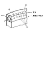
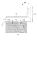
- FIG. 1A and FIG. 1B show cross-sectional views of a mixing channel in a fuel processing apparatus that has already been proposed (see, for example, Patent Document 1).
- the mixing channel 10 connects the transformation unit 20 and the selective oxidation unit 30.
- the mixing channel 10 is further connected to an air supply pipe (40, 41). Further, the air supply pipes (40, 41) extend to the center of the cross section of the mixing channel 10.
- the dashed arrows in FIGS. 1A and 1B indicate the flow of hydrogen-rich gas, and the practice arrows indicate the flow of air.
- the hydrogen-rich gas and the air can be mixed by supplying air through the air supply pipe 40 into the mixing channel 10 through which the hydrogen-rich gas flows. Further, as shown in FIG. 1B, by supplying air through the plurality of openings 42 formed at the tip of the air supply pipe 41 into the mixing flow path 10 through which the hydrogen rich gas flows, the hydrogen rich gas and the air are supplied. Can be mixed.
- air supply pipe extends to the center of the cross section of the mixing flow path 10
- air is supplied to the center of the cross section of the mixing flow path 10 where the flow rate of the hydrogen rich gas is fast, and mixing of the hydrogen rich gas and air is performed. Can be promoted.
- the flow rate of the hydrogen-rich gas flowing in the mixing channel 10 is about 20 times the flow rate of the air supplied from the air supply pipe.
- the flow rate of the hydrogen-rich gas flowing in the mixing channel is large and the flow rate of the supplied air is small, the flow rate of the air is slow and the vortex formed in the mixing channel by the supply of air is small. If the vortex formed is small, the hydrogen-rich gas and air are not sufficiently mixed in the mixing channel.
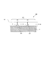
- FIG. 2 is a perspective view of the mixing channel 10 in the fuel processing apparatus disclosed in Patent Document 2. As shown in FIG.
- the mixing channel 10 passes through the room 50 filled with the hydrogen rich gas and has a plurality of gas supply ports 11.
- the gas supply port is formed over the entire length of the mixing channel 10.
- the downstream end of the mixing channel 10 is connected to the air supply unit, and the downstream end of the mixing channel 10 is connected to the selective oxidation unit.
- the hydrogen rich gas having high flow rate is supplied into the mixing channel through which air having low flow rate flows.
- the rich gas is supplied into the mixing channel at a high flow rate. For this reason, compared with the mixing flow path shown in FIGS. 1A and 1B, the hydrogen-rich gas and the air can be mixed efficiently.
- An object of the present invention is to provide a fuel processing apparatus that has a mixing flow path that has a low pressure loss and that can effectively mix a hydrogen-rich gas and air, and that can generate a fuel gas with a low carbon monoxide concentration. Is to provide.
- the inventor divides the mixing channel into a region where the hydrogen-rich gas is supplied and a region where the hydrogen-rich gas and air are diffused to mix the hydrogen-rich gas and air.
- the inventors have found that the hydrogen-rich gas and air can be sufficiently mixed by appropriately selecting the length of the region, and have further studied and completed the invention.
- a reforming unit that generates a hydrogen-rich gas containing carbon monoxide and water; a reforming unit that reacts carbon monoxide in the hydrogen-rich gas with water to produce a hydrogen-rich gas containing a low concentration of carbon monoxide.
- a mixing channel that generates a mixed gas by mixing the hydrogen-rich gas containing low-concentration carbon monoxide and the oxygen-containing air; and connected to an upstream end of the mixing channel, and the mixing channel
- An air supply unit that supplies air to the fuel; and a selective oxidation unit that is connected to a downstream end of the mixing flow path and reacts carbon monoxide and oxygen in the mixed gas to generate a fuel gas.
- a fuel processing apparatus for a battery wherein the mixing channel includes an upstream gas supply region and a downstream gas diffusion region, and two or more connecting the gas supply region and the transformation unit A gas supply port, and the length of the gas diffusion region is Wherein 0.5 to 2 times the length of the gas supply region, the fuel processor.
- the two or more gas supply ports are arranged along a long axis of the mixing channel, and of the two or more gas supply ports, one gas supply port in the circumferential direction of the mixing channel.
- the fuel processing apparatus of this invention can produce
- the gas is supplied through the plurality of gas supply ports into the mixing channel through which air flows, the flow velocity on the upstream side of the mixing channel can be kept low. Thereby, pressure loss can be reduced compared with the case where hydrogen rich gas is made to flow into a mixing channel at once.
- Sectional view of mixing channel in conventional fuel processor The perspective view of the mixing flow path in the conventional fuel processor Flow for generating fuel gas by the fuel processing apparatus of the present invention
- Block diagram of fuel processing apparatus of Embodiment 1 Sectional drawing of the fuel processing apparatus of Embodiment 1 Sectional drawing of the mixing flow path of Embodiment 1
- Sectional drawing of the mixing flow path of Embodiment 5 Sectional drawing of the mixing flow path of Embodiment 6
- the figure which shows the shape of the mixing channel analyzed in the example The figure which shows the analysis result of an Example
- the fuel processing apparatus of the present invention is an apparatus for generating a fuel gas for a fuel cell by subjecting a raw material gas containing carbonized fuel or alcohol and steam to a steam reforming reaction.
- the fuel processing apparatus of the present invention includes a combustion section, an evaporation section, a reforming section, a shift conversion section, an air supply section, a mixing channel, and a selective oxidation section.
- the combustion section is a mechanism for heating the reforming section and the evaporation section.
- a combustion part will not be specifically limited if a flame can be formed, for example, is a burner.
- the evaporation unit is a mechanism for evaporating water to generate water vapor and mixing the raw material gas and water vapor.
- the evaporation unit exchanges heat with the combustion unit, the reforming unit, the shift unit, and the selective oxidation unit, and evaporates water to generate water vapor.
- the generated water vapor is mixed with the raw material gas in the evaporation section.
- the reforming section includes a ruthenium-based or nickel-based catalyst, and is a mechanism for generating a hydrogen-rich gas by a steam reforming reaction from a raw material gas and steam supplied from the evaporation section. Moreover, the hydrogen rich gas produced
- the metamorphic part is a mechanism for generating a hydrogen rich gas containing a low concentration of carbon monoxide from the hydrogen rich gas generated in the reforming part.
- the shift unit includes a platinum-based or copper / zinc-based catalyst, and generates carbon dioxide and hydrogen by a shift reaction from carbon monoxide and water in the hydrogen-rich gas generated in the reforming unit.
- the concentration of carbon monoxide is low means that the concentration of carbon monoxide is 0.5% or less.
- the mixing channel is a channel for generating a mixed gas by mixing a hydrogen-rich gas with a low carbon monoxide concentration generated in the metamorphic part and air.
- the mixing channel is a region constituted by, for example, a circular tube or a rectangular tube.
- the mixing channel is preferably a tubular region constituted by a circular pipe.
- the upstream end of the mixing channel is connected to an air supply unit that supplies air to the mixing channel.
- the air supply unit is, for example, a pump.
- the downstream end of the mixing channel is connected to a selective oxidation unit described later.
- the mixing channel of the present invention employs a system in which hydrogen-rich gas and air are mixed by supplying hydrogen-rich gas through a gas supply port into a mixing channel in which air flows in advance. Therefore, the mixing channel of the present invention has a plurality of gas supply ports connected to the metamorphic part. The hydrogen rich gas that has passed through the metamorphic part is supplied into the mixing channel through a plurality of gas supply ports. The structure of the gas supply port will be described later.
- the selective oxidation unit is a mechanism for generating fuel gas by reacting carbon monoxide and oxygen in the mixed gas generated in the mixing channel.
- carbon monoxide in the mixed gas remaining without reacting in the shift unit is oxidized by oxygen to carbon dioxide. Thereby, the carbon monoxide concentration in the mixed gas is reduced to 10 ppm or less, and fuel gas is generated.
- the fuel processing apparatus having such a configuration can be applied to a fuel cell system such as a home cogeneration system including a fuel cell stack.
- a fuel cell system such as a home cogeneration system including a fuel cell stack.
- the off gas from the anode of the fuel cell stack may be dehumidified by a condenser, reintroduced into the fuel processor, and used as fuel for the combustion section.
- the off gas from the anode may be heat exchanged with the reforming unit.
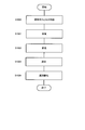
- water and methane which is a raw material gas
- water and source gas are supplied to an evaporation part
- water will be heated in an evaporation part and will become steam.
- the water vapor and the raw material gas are mixed in the evaporation section (S1000).
- the raw material gas and water vapor flow into the reforming section.
- a hydrogen-rich gas containing carbon monoxide is generated from the raw material gas and steam by the following steam reforming reaction (S1001). Further, the hydrogen-rich gas contains unreacted water vapor. CH 4 + H 2 O ⁇ CO + 3H 2
- the hydrogen-rich gas produced in the reforming part flows into the shift part.
- a hydrogen-rich gas containing a low concentration of carbon monoxide is generated from the hydrogen-rich gas generated in the reforming section by the following shift reaction (S1002).
- S1002 shift reaction
- the hydrogen-rich gas containing low-concentration carbon monoxide generated in the metamorphic section flows into the mixing channel through which the air previously supplied from the air supply section flows through the gas supply port.
- a hydrogen-rich gas containing low-concentration carbon monoxide and air are mixed to generate a mixed gas (S1003).
- the mixed gas generated in the mixing channel flows into the selective oxidation unit.
- oxygen in the mixed gas reacts with carbon monoxide that has not been oxidized in the shift portion, and carbon monoxide is oxidized, and the concentration of carbon monoxide in the mixed gas is reduced to 10 ppm or less (S1004).
- the gas that has passed through the selective oxidation unit is taken out as fuel gas.
- the fuel gas generated in this way flows out from the selective oxidation unit and is supplied to the fuel cell.
- a fuel cell generates power using hydrogen in fuel gas and an oxidizing gas containing oxygen such as air.
- step S1003 the hydrogen-rich gas and air that have passed through the metamorphic part are mixed in the mixing flow path to generate a mixed gas.
- the hydrogen-rich gas and air may not be sufficiently mixed in the mixing channel. If the hydrogen rich gas and the air are not sufficiently mixed and flow into the selective oxidation unit, the carbon monoxide in the hydrogen rich gas is not sufficiently oxidized, and the carbon monoxide concentration of the fuel gas increases.
- the fuel processing apparatus of the present invention is characterized in that hydrogen-rich gas and air can be sufficiently mixed in a mixing channel.
- the mixing channel is composed of an upstream gas supply region and a downstream gas diffusion region; and has a gas supply port that connects the gas supply region and the metamorphic part.
- the gas supply region is connected to the transformation unit via the gas supply port, and the gas diffusion region does not have the gas supply port.
- the gas supply area is an area where hydrogen rich gas is supplied in the mixing channel.
- the gas supply region is connected to the transformation unit by a plurality of gas supply ports. Therefore, the hydrogen-rich gas containing low-concentration carbon monoxide generated in the metamorphic portion flows into the gas supply region of the mixing channel through the gas supply port.
- the number of gas supply ports is not particularly limited, but is 2 to 6, for example.
- the diameter of the gas supply port can be appropriately selected depending on the length and diameter of the mixing channel, and is, for example, 2 to 5 mm.
- the gas supply ports are preferably arranged at predetermined intervals along the long axis of the mixing channel. Moreover, the circumferential position of the mixing flow path of each gas supply port may be the same (see Embodiment 1) or may be different (see Embodiment 2).
- the circumferential position of the mixing channel of one gas supply port is the circumferential position of the mixing channel of the other gas supply port. It is preferable to face the position (see Embodiment 2).
- the stirring of the hydrogen rich gas and the air can be promoted by changing the circumferential position of the mixing channel of each gas supply port.
- the diameter of the gas supply port on the most upstream side is the maximum and the diameter of the gas supply port on the most downstream side is the minimum (see Embodiment 3). More specifically, the diameter of the gas supply port is preferably gradually reduced along the direction of the gas flowing through the mixing flow path.
- the gas diffusion region does not have a gas supply port, and is a region for ensuring time for the hydrogen-rich gas and air to be uniformly mixed by the diffusion effect. Therefore, the gas diffusion region is designed so that it takes a certain time for the hydrogen-rich gas and air that have passed through the gas supply region to reach the selective oxidation unit. Thus, the hydrogen-rich gas and air that have passed through the gas supply region are sufficiently mixed by the diffusion effect in the process of flowing through the gas diffusion region.
- the gas diffusion region has a certain volume so that it takes a certain time for the hydrogen-rich gas and air that have passed through the gas supply region to reach the selective oxidation unit.
- the length of the gas diffusion region may be adjusted or the diameter of the gas diffusion region may be adjusted, but the length of the gas diffusion region may be adjusted. preferable. For example, when the volume of the gas diffusion region is adjusted by increasing the diameter of the gas diffusion region, the flow rates of the hydrogen rich gas and air flowing through the mixing flow path in the gas diffusion region are reduced, and the hydrogen rich gas and air are mixed. It becomes difficult.
- the length of the gas diffusion region is preferably selected as appropriate depending on the properties of the gas, the diameter of the mixing channel, and the like. Specifically, the diameter of the mixing channel is D (m), the flow velocity (m / second) of the gas (hydrogen rich gas and air) flowing in the gas diffusion region is U, and it is necessary for the gas to diffuse 1 m.
- the time (second / m) is t
- the length of such a gas diffusion region that satisfies the equation is usually 0.5 to 2 times the length of the gas supply region.
- the hydrogen rich gas and air may not be sufficiently mixed in the gas diffusion region.
- the apparatus size becomes too large.
- the length of the gas diffusion region is twice or more than the length of the gas supply region, the temperature of the mixed gas is lowered, and the oxidation reaction of carbon monoxide may be insufficient in the selective oxidation part.
- the pressure loss increases.
- the hydrogen-rich gas having a low carbon monoxide concentration generated in the shift section 1) flows into the gas supply region through which the air flows through the gas supply port, where the hydrogen-rich gas and the air 2) In the process of passing through the gas diffusion region, the hydrogen-rich gas and the air are sufficiently mixed by the diffusion effect to generate a mixed gas.
- the produced mixed gas flows into the selective oxidation unit.
- the hydrogen-rich gas and air pass through the gas diffusion region that does not have the gas supply port, even if mixing of the hydrogen-rich gas and air in the gas supply region is insufficient. In the process of passing through the gas diffusion region, the mixed gas is sufficiently mixed to generate a mixed gas.
- the mixing channel is divided into a gas supply region and a gas diffusion region; by making the length of the gas diffusion region 0.5 to 2 times the length of the gas supply region;
- the hydrogen-rich gas and the air can be sufficiently mixed, and the gas mixture having a uniform ratio of the hydrogen-rich gas and the air can be supplied to the selective oxidation unit.
- the fuel processing apparatus of the present invention can stably supply the fuel gas even when the amount of the hydrogen-rich gas generated and the supplied air varies depending on the operating state of the fuel cell.
- the gas is supplied through the plurality of gas supply ports into the mixing channel through which air flows, the flow velocity on the upstream side of the mixing channel can be kept low. Thereby, pressure loss can be reduced as compared with the case where hydrogen-rich gas is allowed to flow into the mixing channel from only one supply port (see Embodiment 1).
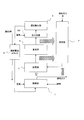
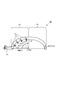
- FIG. 4 shows a schematic diagram of the fuel processing apparatus of the first embodiment
- FIG. 5 shows a cross-sectional view of the fuel processing apparatus of the first embodiment.
- the hatched arrows in FIG. 4 indicate the movement of thermal energy
- the fuel processing apparatus of the first embodiment includes a combustion unit 1, an evaporation unit 2, a reforming unit 3, a shift unit 4, a mixing channel 100, and selective oxidation. Part 5.
- the fuel processing apparatus may be connected to the fuel cell stack 6.
- the fuel processor When the fuel processor is connected to the fuel cell stack 6, the fuel gas generated in the selective oxidation unit 5 is supplied to the anode of the fuel cell stack 6, and the off-gas at the anode of the fuel cell stack 6 is supplied to the condenser (non-reactor). It is supplied to the combustion section 1 via the figure).
- the fuel processing apparatus of Embodiment 1 is characterized by the configuration of the mixing channel 100.
- the configuration of the mixing channel 100 will be described in detail.
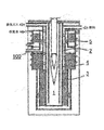
- FIG. 6 is an enlarged view of the mixing channel 100 of the fuel processing apparatus shown in FIG.
- the total length of the mixing channel 100 is, for example, 100 to 200 mm.
- the diameter of the mixing channel 100 is appropriately selected according to the output of the fuel cell system. For example, when the output of the fuel cell system is 750 W, the cross-sectional area of the mixing channel 100 is 12 to 50 mm 2 .
- the mixing channel 100 includes a gas supply region 110 and a gas diffusion region 120.
- the length of the gas supply region 110 is, for example, 50 to 100 mm.
- the length of the gas diffusion region 120 is, for example, 50 to 100 mm.
- the gas supply region 110 is connected to the air inlet 101 and has a first gas supply port 111 and a second gas supply port 112.
- the interval is equal.
- the gas diffusion region 120 does not have a gas supply port.
- the area of the gas supply port is, for example, 12 to 40 mm 2 when the output of the fuel cell system is 750 w.
- the arrows in FIG. 6 indicate the flow of air and hydrogen rich gas.
- air previously supplied from the air inlet 101 flows through the gas supply region 110. Further, the hydrogen-rich gas that has passed through the transformation unit 4 flows into the gas supply region 110 through the first gas supply port 111 and the second gas supply port 112.
- the flow rate of the hydrogen rich gas is approximately 20 times the flow rate of the air.
- the hydrogen-rich gas having a high flow rate flows into the gas supply region 110 through which the air having a low flow rate flows through the gas supply hole.
- the rich gas can generate vortices in the gas supply region 110 and promote stirring of the hydrogen-rich gas in the gas supply region 110 and air.
- the hydrogen-rich gas and air that have been stirred to some extent in the gas supply region 110 flow into the gas diffusion region 120.
- the length of the gas diffusion region 120 is set so as to ensure a time during which the hydrogen-rich gas and air are sufficiently mixed by the diffusion effect. Therefore, the hydrogen rich gas and the air are sufficiently mixed by the diffusion effect in the process of flowing through the gas diffusion region 120.
- the mixing channel is divided into the gas supply region and the gas diffusion region, and the length of the gas diffusion region is about 0.5 to 2 times the length of the gas supply region.
- the pressure loss P of the entire gas supply region 110 is defined as a pressure loss between the air inlet 101 and the first gas supply port 111 as P0; and a pressure loss between the first gas supply port 111 and the second gas supply port as P1.
- P P0 + P1 + P2 (1)
- the pressure loss is proportional to the gas flow rate in the case of laminar flow. Therefore, the gas flow rate between the air inlet 101 and the first gas supply port 111 is Q0; the gas flow rate between the first gas supply port 111 and the second gas supply port is Q1; the second gas supply port 112, the gas flow rate between the gas supply region 110 and the downstream end of the gas supply region 110 is Q2.
- the pressure loss (P0, P1, P2) is defined as in the following formula (2).
- L is the length of 1/3 of the total length of the gas supply region 110, and ⁇ and ⁇ are functions of the gas viscosity and the channel width.
- the flow rate of air is approximately 1/20 of the flow rate of hydrogen-rich gas, and thus may be approximated to 0. Therefore, the gas flow rate can be defined as the following equation (3).
- Q0 ⁇ 0 Q2 2 ⁇ Q1 (3)
- the pressure loss P in the gas supply region 110 can be defined as the following equation (4).
- P 3 ⁇ ⁇ Q1 ⁇ L (4)
- the gas supply region 110 does not have the second gas supply port 112; when hydrogen-rich gas is supplied only from the first gas supply port 111, the gas supply region 110 downstream of the first gas supply port 111 The flow rate is constant. Therefore, the pressure loss P ′ in the gas supply region 110 is defined as the following formula (5).
- P0 ⁇ ⁇ Q0 ⁇ L
- P1 ⁇ ⁇ 2Q1 ⁇ L
- the pressure loss P ′ in the gas supply region 110 is defined as the following formula (6).
- P ′ 4 ⁇ ⁇ Q1 ⁇ L (6)
- the pressure loss when two gas supply ports are provided, the pressure loss can be increased to about 3 ⁇ 4 times that when only one gas supply port is provided. Further, when the gas supply ports are arranged at equal intervals along the flow of the mixing channel, the pressure loss can be further reduced by increasing the number of gas supply ports.
- the hydrogen-rich gas and air can be mixed with a low pressure loss.
- the fuel processing apparatus of the second embodiment is the same as the fuel processing apparatus of the first embodiment except that the arrangement pattern of the gas supply ports in the gas supply region is different. Therefore, in Embodiment 2, only the gas supply region of the mixing channel will be described.
- FIG. 7A is a perspective view of the gas supply region 210 in the mixing channel 200 of the second embodiment.
- the gas supply region 210 is connected to the air inlet 101 and has a first gas supply port 211, a second gas supply port 212, a third gas supply port 213, and a fourth gas supply port 214. .
- the positions of the gas supply ports in the circumferential direction of the mixing channel 200 are different.
- the circumferential interval of the mixing channel 200 between the first gas supply port 211 and the second gas supply port 212; and the circle of the mixing channel 200 between the second gas supply port 212 and the third gas supply port 213 It is preferable that the circumferential interval is equal to the circumferential interval of the mixing channel 200 between the third gas supply port 213 and the fourth gas supply port 214.
- the circumferential position of the mixing channel 200 of the first gas supply port 211 and the circumferential position of the mixing channel 200 of the third gas supply port 213 are opposed to each other; and the second gas supply port The position in the circumferential direction of the mixing channel 200 of 212 and the position in the circumferential direction of the mixing channel 200 of the fourth gas supply port 214 are opposed to each other.
- FIG. 7B is a cross-sectional view taken along line AA of the mixing channel 200 in the gas supply region 210 shown in FIG. 7A.
- the arrows in FIG. 7B indicate the flow of air and hydrogen rich gas.
- the circumferential positions of the mixing flow paths 200 of the gas supply ports are different. Thereby, stirring of hydrogen rich gas and air can be promoted in the gas supply region 210.
- the relationship between the positions of the gas supply ports in the circumferential direction of the mixing channel 200 being different from the stirring of the hydrogen-rich gas and air in the gas supply region 210 will be described.
- the air A1 supplied through the air inlet 101 is agitated with the hydrogen rich gas H1 flowing in through the first gas supply port 211.
- the air A2 flowing through the wall surface of the mixing channel 200 facing the first gas supply port 211 passes through the region where the first gas supply port 211 is formed without being stirred with the hydrogen rich gas H1. May end up.
- the air A2 easily passes without being stirred with the hydrogen-rich gas H1.
- the third gas supply port 213 is disposed on the wall surface side facing the first gas supply port 211 in the wall surface of the mixing channel 200. For this reason, the air A2 that has passed without being mixed with the hydrogen-rich gas H1 is stirred with the hydrogen-rich gas H2 that has flowed through the third gas supply port 213.
- the fuel processing apparatus of the third embodiment is the same as the fuel processing apparatus of the first embodiment except that the arrangement pattern of the gas supply ports in the gas supply region is different. Therefore, in Embodiment 3, only the gas supply region in the mixing channel will be described.
- FIG. 8A is a perspective view of the gas supply region 310 in the mixing channel 300 of the present embodiment.
- the gas supply region 310 is connected to the air inlet 101 and includes a first gas supply port 311, a second gas supply port 312, and a third gas supply port 313.
- the diameter of the first gas supply port 311 on the upstream side of the mixing channel 300 is the largest, and the diameter of the third gas supply port 313 on the downstream side is the smallest.
- the present embodiment is characterized in that the diameter of the gas supply port decreases stepwise along the direction in which the gas flows in the mixing channel 300.
- FIG. 8B is a cross-sectional view taken along line AA of the mixing channel 300 in the gas supply region 310 shown in FIG. 8A.
- the arrows in FIG. 3B indicate the flow of air and hydrogen rich gas.
- the gas flow rate is small upstream of the gas supply region 310 to which no hydrogen rich gas is supplied; the hydrogen rich gas flows through the gas supply port. As it flows in, the gas flow rate increases stepwise.
- the gas flow rate increases stepwise.
- the upstream first gas supply port 311 since the upstream first gas supply port 311 has a large diameter, the flow rate of the hydrogen-rich gas flowing from the upstream first gas supply port 311 is large; the downstream third gas supply port Since the diameter of 313 is small, the flow rate of the hydrogen rich gas flowing from the third gas supply port 313 on the downstream side is small. For this reason, the flow rate of the gas flowing in the gas supply region 310 is made uniform, and the hydrogen-rich gas and the air can be stirred more effectively.
- Embodiment 4 a mode in which the mixing channel has a plurality of barriers in the gas supply region will be described.
- the fuel processing apparatus of the fourth embodiment is the same as the fuel processing apparatus of the first embodiment, except that the mixing channel has a plurality of barriers in the gas supply region. Therefore, in Embodiment 4, only the gas supply region in the mixing channel will be described.
- FIG. 9 shows a cross-sectional view of the gas supply region 410 in the mixing channel 400 of the fourth embodiment.
- the gas supply region 410 is connected to the air inlet 101 and has a plurality of barriers 401.
- the barrier 401 is provided in a region of the wall surface of the mixing channel 400 facing the gas supply port, and blocks a part of the gas flow in the mixing channel 400 near the gas supply port.
- the arrows in FIG. 9 indicate the flow of hydrogen rich gas and air.
- air previously supplied from the air inlet 101 flows in the gas supply region 410.
- the hydrogen-rich gas that has passed through the transformation unit 4 flows into the gas supply region 410 through the first gas supply port 411 and the second gas supply port 412.
- the air that flows in from the air inlet 101 is guided to the vicinity of the gas supply port by the barrier 401 disposed in the vicinity of the gas supply port (slightly upstream). For this reason, even if the flow rate of the hydrogen-rich gas flowing through the gas supply port is slow and vortices are formed only in the vicinity of the gas supply port, air is guided to the vicinity of the gas supply port by the barrier 401.
- the hydrogen-rich gas and air can be sufficiently stirred.
- the fuel processing apparatus of the fifth embodiment is the same as the fuel processing apparatus of the first embodiment except that the shape of the gas supply port of the gas supply region is different. Therefore, in Embodiment 5, only the gas supply region in the mixing channel will be described.
- FIG. 10 shows a cross-sectional view of the gas supply region 510 in the mixing channel 500 of the fifth embodiment.
- the gas supply region 510 is connected to the air inlet 101 and has a first gas supply port 511 and a second gas supply port 512.
- the first gas supply port 511 and the second gas supply port 512 are narrowed toward the mixing channel 500.
- the arrows in FIG. 10 indicate the flow of hydrogen rich gas and air.
- air previously supplied from the air inlet 101 flows in the gas supply region 510.
- the hydrogen-rich gas that has passed through the transformation unit 4 flows into the gas supply region 510 through the first gas supply port 511 and the second gas supply port 512.
- the hydrogen-rich gas flowing into the gas supply region 510 through the first gas supply port 511 and the second gas supply port 512 The flow rate becomes faster. Thereby, stirring with hydrogen rich gas and air is accelerated
- the fuel processing apparatus according to the sixth embodiment is the same as the fuel processing apparatus according to the first embodiment except that the shape of the gas supply port of the gas supply region is different. Therefore, in Embodiment 6, only the gas supply region of the mixing channel will be described.
- FIG. 11 shows a cross-sectional view of the gas supply region 610 in the mixing channel 600 of the sixth embodiment.
- the gas supply region 610 is connected to the air inlet 101 and has a first gas supply port 611 and a second gas supply port 612.
- the first gas supply port 611 and the second gas supply port 612 extend to the center of the cross section of the mixing channel 600.
- FIG. 11 indicate the flow of hydrogen rich gas and air.
- air previously supplied from the air inlet 101 flows in the gas supply region 510.
- the hydrogen-rich gas that has passed through the transformation unit 4 flows into the gas supply region 610 through the first gas supply port 611 and the second gas supply port 612.
- the flow rate of the gas flowing in the mixing channel 600 is faster at the center of the cross section of the mixing channel 600 than in the vicinity of the wall surface of the mixing channel 600.
- the gas supply port extends, the hydrogen-rich gas that has flowed through the gas supply port can be guided to the center of the cross section of the mixing channel 600 where the gas flow rate is fast. Thereby, stirring with hydrogen rich gas and air can be accelerated
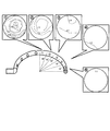
- the shape of the mixing channel 100 analyzed in the example is shown in FIG.
- the mixing channel 100 was constituted by a semicircular circular tube.
- the inner diameter of the circular tube was 6 mm.
- the diameter D of the semicircle was 120 mm.
- the length of the gas supply region 110 was 94 mm, and the length of the gas diffusion region was 94 mm.
- the gas supply ports 111 are arranged along the gas flow.
- the diameter of the gas supply port 111 was 4 mm.
- the four gas supply ports were arranged every 22.5 ° as shown in FIG.
- Air and hydrogen rich gas flow rates The air flow rate was 0.6 L / min, and the hydrogen rich gas flow rate was 18 L / min.
- Hydrogen rich gas composition The composition of the hydrogen rich gas was set as follows. Methane 1.8%; water vapor 18.7%; carbon dioxide 15.4%; carbon monoxide 0.2%; hydrogen 63.9%.
- the fuel processing apparatus of the present invention can stably generate fuel gas for a fuel cell. Therefore, the fuel processing apparatus of the present invention is useful for a fuel cell system such as a home cogeneration system.
- Fuel cell stack 100 200, 300, 400, 500, 600 Mixing flow path 101 Air inlet 110, 210, 310, 410, 510, 610 Gas supply area 120 Gas diffusion Region 111, 211, 311, 411, 511, 611 First gas supply port 112, 212, 312, 412, 512, 612 Second gas supply port 213, 313 Third gas supply port 214 Fourth gas supply port 401 Barrier
Landscapes
- Chemical & Material Sciences (AREA)
- Chemical Kinetics & Catalysis (AREA)
- Organic Chemistry (AREA)
- Engineering & Computer Science (AREA)
- Combustion & Propulsion (AREA)
- Inorganic Chemistry (AREA)
- Health & Medical Sciences (AREA)
- General Health & Medical Sciences (AREA)
- Life Sciences & Earth Sciences (AREA)
- Manufacturing & Machinery (AREA)
- Sustainable Development (AREA)
- Sustainable Energy (AREA)
- Electrochemistry (AREA)
- General Chemical & Material Sciences (AREA)
- Fuel Cell (AREA)
- Hydrogen, Water And Hydrids (AREA)
Abstract
Description
このように、混合流路内を流れる水素リッチガスの流量が多く、供給される空気の流量が小さいと、空気の流速が遅く、空気の供給によって混合流路内に形成される渦が小さい。形成される渦が小さいと、混合流路内で水素リッチガスと空気とが十分に混合されない。また、空気の流速を速くするために空気の噴出孔を小さくすることも考えられるが、その場合、圧力損失が大きくなってしまう。
[1]一酸化炭素および水を含む水素リッチガスを生成する改質部と;前記水素リッチガス中の一酸化炭素と水とを反応させて、低濃度の一酸化炭素を含む水素リッチガスを生成する変成部と;前記低濃度の一酸化炭素を含む水素リッチガスと酸素を含む空気とを混合して、混合ガスを生成する混合流路と;前記混合流路の上流端と接続し、前記混合流路に空気を供給する空気供給部と;前記混合流路の下流端と接続し、前記混合ガス中の一酸化炭素と酸素とを反応させて、燃料ガスを生成する選択酸化部と;を有する燃料電池用の燃料処理装置であって、前記混合流路は、上流側のガス供給領域と、下流側のガス拡散領域とからなり、かつ前記ガス供給領域と前記変成部とを接続する2以上のガス供給口を有し、前記ガス拡散領域の長さは、前記ガス供給領域の長さの0.5~2倍である、燃料処理装置。
[2]前記2以上のガス供給口は、前記混合流路の長軸に沿って配列され、前記2以上のガス供給口のうち、1のガス供給口の前記混合流路の円周方向の位置と、他のガス供給口の前記混合流路の円周方向の位置とは異なる、[1]に記載の燃料処理装置。
[3]前記1のガス供給口の前記混合流路の円周方向の位置と、他のガス供給口の前記混合流路の円周方向の位置とは対向する、[2]に記載の燃料処理装置。
[4]前記ガス供給口のうち、最上流側のガス供給口の口径が最も大きく、最下流側のガス供給口の口径が最も小さい、[1]~[3]のいずれか一つに記載の燃料処理装置。
[5]前記混合流路内に設けられた2以上の障壁をさらに有し、前記障壁は、前記ガス供給口近辺の混合流路内のガスの流れの一部を遮る、[1]~[4]のいずれか一つに記載の燃料処理装置。
[6]前記ガス供給口の口径は、前記混合流路に向かって絞り込まれている、[1]~[5]のいずれか一つに記載の燃料処理装置。
本発明の燃料処理装置は、燃焼部、蒸発部、改質部、変成部、空気供給部、混合流路および選択酸化部を有する。
CH4+H2O→CO+3H2
CO+H2O→CO2+H2
L=U×D×t
図4は、実施の形態1の燃料処理装置の模式図を示し、図5は実施の形態1の燃料処理装置の断面図を示す。図4における斜線矢印は熱エネルギの動きを示し、図4および図5における実線矢印は、ガス(原料ガス、水蒸気または水素リッチガス)の流れを示す。
一方、ガス拡散領域120はガス供給口を有さない。ガス供給口の面積は、燃料電池システムの出力が750wであった場合、例えば12~40mm2である。
P=P0+P1+P2 (1)
P0=α×Q0×L
P1=β×Q1×L
P2=β×Q2×L
Q2=2×Q1+Q0 (2)
Q0≒0
Q2=2×Q1 (3)
P=3×βQ1×L (4)
P0=α×Q0×L
P1=β×2Q1×L
P2=β×2Q1×L
P’=P0+P1+P2 (5)
P’=4×βQ1×L (6)
実施の形態1では、各ガス供給口の混合流路の円周方向の位置が同じである形態について説明した。実施の形態2では、各ガス供給口の混合流路の円周方向の位置が異なる形態について説明する。
実施の形態1および実施の形態2では、各ガス供給口の口径が全て同じである形態について説明した。実施の形態3ではガス供給口の口径が異なる形態について説明する。
実施の形態4では、混合流路がガス供給領域内に複数の障壁を有する形態について説明する。
実施の形態5では、ガス供給口の口径が、混合流路に向かって絞られている形態について説明する。
実施の形態6では、ガス供給口が、混合流路の横断面の中心まで延びている形態について説明する。
シミュレーションではANSYS社製のFLUENT6.2を用いた。
実施例で解析した混合流路100の形状を図12に示す。図12に示されるように混合流路100を半円型の円管によって構成した。円管の内径は6mmとした。半円の直径Dは120mmとした。また、ガス供給領域110の長さを94mmとし、ガス拡散領域の長さを94mmとした。ガス供給領域110には、ガス供給口111をガスの流れに沿って配列した。ガス供給口111の口径を4mmとした。4つのガス供給口は図12に示すように22.5°ごとに配置した。
空気の流量を0.6L/minとし、水素リッチガスの流量を18L/minとした。
水素リッチガスの組成を以下のように設定した。
メタン1.8%;水蒸気18.7%;二酸化炭素15.4%;一酸化炭素0.2%;水素63.9%。
図13に示されるように、18°ごとにガス拡散領域の断面における酸素のモル濃度と一酸化炭素のモル濃度との比率(酸素のモル濃度/一酸化炭素のモル濃度)を測定した。酸素は空気に含まれ、一酸化炭素は水素リッチガスに含まれるので、酸素のモル濃度と一酸化炭素のモル濃度との比率のばらつきが小さいほど、水素リッチガスと空気とが十分に混合されていることを示唆する。
実施例の解析結果を図13に示す。図13に示されるようにガス拡散領域の最も上流の断面(1)では、酸素のモル濃度と一酸化炭素のモル濃度との比率のばらつきの幅は、2.4~4.0となった。一方、断面(2)では、酸素のモル濃度と一酸化炭素のモル濃度との比率のばらつきの幅は、2.8~3.2となり、断面(3)では、2.8~3.0となる。そして、断面(5)では、酸素のモル濃度と一酸化炭素のモル濃度との比率のばらつきは確認されなかった。
2 蒸発部
3 改質部
4 変成部
5 選択酸化部
6 燃料電池スタック
100、200、300、400、500、600 混合流路
101 空気流入口
110、210、310、410、510、610 ガス供給領域
120 ガス拡散領域
111、211、311、411、511、611 第1ガス供給口
112、212、312、412、512、612 第2ガス供給口
213、313 第3ガス供給口
214 第4ガス供給口
401 障壁
Claims (6)
- 一酸化炭素および水を含む水素リッチガスを生成する改質部と;
前記水素リッチガス中の一酸化炭素と水とを反応させて、低濃度の一酸化炭素を含む水素リッチガスを生成する変成部と;
前記低濃度の一酸化炭素を含む水素リッチガスと酸素を含む空気とを混合して、混合ガスを生成する混合流路と;
前記混合流路の上流端と接続し、前記混合流路に空気を供給する空気供給部と;
前記混合流路の下流端と接続し、前記混合ガス中の一酸化炭素と酸素とを反応させて、燃料ガスを生成する選択酸化部と;を有する燃料電池用の燃料処理装置であって、
前記混合流路は、上流側のガス供給領域と、下流側のガス拡散領域とからなり、かつ
前記ガス供給領域と前記変成部とを接続する2以上のガス供給口を有し、
前記ガス拡散領域の長さは、前記ガス供給領域の長さの0.5~2倍である、燃料処理装置。 - 前記2以上のガス供給口は、前記混合流路の長軸に沿って配列され、
前記2以上のガス供給口のうち、1のガス供給口の前記混合流路の円周方向の位置と、他のガス供給口の前記混合流路の円周方向の位置とは異なる、請求項1に記載の燃料処理装置。 - 前記1のガス供給口の前記混合流路の円周方向の位置と、他のガス供給口の前記混合流路の円周方向の位置とは対向する、請求項2に記載の燃料処理装置。
- 前記ガス供給口のうち、最上流側のガス供給口の口径が最も大きく、最下流側のガス供給口の口径が最も小さい、請求項1に記載の燃料処理装置。
- 前記混合流路内に設けられた2以上の障壁をさらに有し、
前記障壁は、前記ガス供給口近辺の混合流路内のガスの流れの一部を遮る、請求項1に記載の燃料処理装置。 - 前記ガス供給口の口径は、前記混合流路に向かって絞り込まれている、請求項1に記載の燃料処理装置。
Priority Applications (5)
| Application Number | Priority Date | Filing Date | Title |
|---|---|---|---|
| JP2009545737A JP4542205B2 (ja) | 2008-05-30 | 2009-05-26 | 燃料処理装置 |
| US12/668,977 US8398731B2 (en) | 2008-05-30 | 2009-05-26 | Fuel treatment device with gas supply and diffusion regions |
| KR1020097026810A KR101143418B1 (ko) | 2008-05-30 | 2009-05-26 | 연료 처리 장치 |
| CN2009800005500A CN101743192B (zh) | 2008-05-30 | 2009-05-26 | 燃料处理装置 |
| EP09754432.4A EP2281776B1 (en) | 2008-05-30 | 2009-05-26 | Fuel processor |
Applications Claiming Priority (2)
| Application Number | Priority Date | Filing Date | Title |
|---|---|---|---|
| JP2008-143028 | 2008-05-30 | ||
| JP2008143028 | 2008-05-30 |
Publications (1)
| Publication Number | Publication Date |
|---|---|
| WO2009144923A1 true WO2009144923A1 (ja) | 2009-12-03 |
Family
ID=41376813
Family Applications (1)
| Application Number | Title | Priority Date | Filing Date |
|---|---|---|---|
| PCT/JP2009/002322 WO2009144923A1 (ja) | 2008-05-30 | 2009-05-26 | 燃料処理装置 |
Country Status (6)
| Country | Link |
|---|---|
| US (1) | US8398731B2 (ja) |
| EP (1) | EP2281776B1 (ja) |
| JP (1) | JP4542205B2 (ja) |
| KR (1) | KR101143418B1 (ja) |
| CN (1) | CN101743192B (ja) |
| WO (1) | WO2009144923A1 (ja) |
Cited By (1)
| Publication number | Priority date | Publication date | Assignee | Title |
|---|---|---|---|---|
| JP2011207703A (ja) * | 2010-03-30 | 2011-10-20 | Jx Nippon Oil & Energy Corp | 水素製造装置及び燃料電池システム |
Families Citing this family (2)
| Publication number | Priority date | Publication date | Assignee | Title |
|---|---|---|---|---|
| JP5958721B2 (ja) | 2012-02-09 | 2016-08-02 | パナソニックIpマネジメント株式会社 | 燃料処理装置 |
| CN105184036B (zh) * | 2015-05-20 | 2018-06-15 | 中国水利水电科学研究院 | 一种城市居民节水潜力的计算系统 |
Citations (5)
| Publication number | Priority date | Publication date | Assignee | Title |
|---|---|---|---|---|
| JP2003226504A (ja) | 2002-01-31 | 2003-08-12 | Aisin Seiki Co Ltd | 燃料改質装置 |
| WO2003078311A1 (fr) * | 2002-03-15 | 2003-09-25 | Matsushita Electric Works, Ltd. | Dispositif de reformage et son mode de fonctionnement |
| JP2004262725A (ja) | 2003-03-04 | 2004-09-24 | Ishikawajima Harima Heavy Ind Co Ltd | 選択酸化反応装置 |
| JP2006176398A (ja) * | 2004-11-29 | 2006-07-06 | Matsushita Electric Ind Co Ltd | 水素製造装置及びそれを備える燃料電池発電装置 |
| JP2008143028A (ja) | 2006-12-11 | 2008-06-26 | Kimoto & Co Ltd | 表示用フィルムおよび表示方法 |
Family Cites Families (8)
| Publication number | Priority date | Publication date | Assignee | Title |
|---|---|---|---|---|
| GB9826222D0 (en) | 1998-12-01 | 1999-01-20 | Johnson Matthey Plc | Improved reactor |
| WO2000063114A1 (fr) * | 1999-04-20 | 2000-10-26 | Tokyo Gas Co., Ltd. | Reformeur cylindrique monotube et procede pour faire fonctionner ledit reformeur |
| CA2357960C (en) * | 2000-10-10 | 2007-01-30 | Tokyo Gas Co., Ltd. | Single-pipe cylinder type reformer |
| CA2489299A1 (en) | 2002-06-13 | 2003-12-24 | Darryl Pollica | Preferential oxidation reactor temperature regulation |
| US7195742B2 (en) * | 2002-07-26 | 2007-03-27 | Utc Fuel Cells, Llc | Preferential oxidation reactor and process |
| EP1557395B1 (en) * | 2004-01-22 | 2012-07-04 | Panasonic Corporation | Hydrogen generator and fuel cell system |
| CA2521698A1 (en) | 2004-02-12 | 2005-08-25 | Ishikawajima-Harima Heavy Industries, Co., Ltd. | Selective oxidation reactor |
| KR100667953B1 (ko) * | 2005-07-29 | 2007-01-11 | 삼성에스디아이 주식회사 | 개질기 및 이를 포함하는 연료 전지 시스템 |
-
2009
- 2009-05-26 CN CN2009800005500A patent/CN101743192B/zh not_active Expired - Fee Related
- 2009-05-26 JP JP2009545737A patent/JP4542205B2/ja not_active Expired - Fee Related
- 2009-05-26 EP EP09754432.4A patent/EP2281776B1/en not_active Not-in-force
- 2009-05-26 WO PCT/JP2009/002322 patent/WO2009144923A1/ja active Application Filing
- 2009-05-26 US US12/668,977 patent/US8398731B2/en active Active
- 2009-05-26 KR KR1020097026810A patent/KR101143418B1/ko not_active IP Right Cessation
Patent Citations (5)
| Publication number | Priority date | Publication date | Assignee | Title |
|---|---|---|---|---|
| JP2003226504A (ja) | 2002-01-31 | 2003-08-12 | Aisin Seiki Co Ltd | 燃料改質装置 |
| WO2003078311A1 (fr) * | 2002-03-15 | 2003-09-25 | Matsushita Electric Works, Ltd. | Dispositif de reformage et son mode de fonctionnement |
| JP2004262725A (ja) | 2003-03-04 | 2004-09-24 | Ishikawajima Harima Heavy Ind Co Ltd | 選択酸化反応装置 |
| JP2006176398A (ja) * | 2004-11-29 | 2006-07-06 | Matsushita Electric Ind Co Ltd | 水素製造装置及びそれを備える燃料電池発電装置 |
| JP2008143028A (ja) | 2006-12-11 | 2008-06-26 | Kimoto & Co Ltd | 表示用フィルムおよび表示方法 |
Non-Patent Citations (1)
| Title |
|---|
| See also references of EP2281776A4 |
Cited By (3)
| Publication number | Priority date | Publication date | Assignee | Title |
|---|---|---|---|---|
| JP2011207703A (ja) * | 2010-03-30 | 2011-10-20 | Jx Nippon Oil & Energy Corp | 水素製造装置及び燃料電池システム |
| EP2554512A1 (en) * | 2010-03-30 | 2013-02-06 | JX Nippon Oil & Energy Corporation | Hydrogen production apparatus and fuel cell system |
| EP2554512A4 (en) * | 2010-03-30 | 2014-01-22 | Jx Nippon Oil & Energy Corp | DEVICE FOR HYDROGEN PRODUCTION AND FUEL CELL SYSTEM |
Also Published As
| Publication number | Publication date |
|---|---|
| CN101743192B (zh) | 2013-07-03 |
| EP2281776A4 (en) | 2012-06-13 |
| JPWO2009144923A1 (ja) | 2011-10-06 |
| US20100183483A1 (en) | 2010-07-22 |
| EP2281776A1 (en) | 2011-02-09 |
| US8398731B2 (en) | 2013-03-19 |
| EP2281776B1 (en) | 2016-08-24 |
| JP4542205B2 (ja) | 2010-09-08 |
| CN101743192A (zh) | 2010-06-16 |
| KR20100012038A (ko) | 2010-02-04 |
| KR101143418B1 (ko) | 2012-05-23 |
Similar Documents
| Publication | Publication Date | Title |
|---|---|---|
| US7484590B2 (en) | Fuel cell system with muffler | |
| WO2010087791A1 (en) | Distributively cooled, integrated water-gas shift reactor and vaporizer | |
| US7846398B2 (en) | Micro reactor having micro flow-guiding blocks | |
| JP5123442B2 (ja) | 水素生成装置および燃料電池発電システム | |
| JP4542205B2 (ja) | 燃料処理装置 | |
| CN107107009B (zh) | 一氧化碳氧化装置 | |
| JP2005126260A (ja) | 燃料改質器用混合装置 | |
| JP4213895B2 (ja) | 燃料改質装置 | |
| EP1184336A1 (en) | Apparatus for selective oxidation of carbon monoxide | |
| JP2004182494A (ja) | 改質ガスのco低減装置 | |
| US7416799B2 (en) | Oxidizer for a fuel cell system | |
| JP3515438B2 (ja) | Co除去装置及び燃料電池発電システム | |
| JP2007320816A (ja) | 燃料処理装置 | |
| JP2004247241A (ja) | 燃料電池用改質器 | |
| JP2011098840A (ja) | 燃料電池用水素生成装置 | |
| JP2002025597A (ja) | 燃料電池用の改質装置とその運転方法 | |
| JP4163657B2 (ja) | 燃料改質装置 | |
| JP4505367B2 (ja) | 水素燃料供給システム | |
| JP2004196614A (ja) | Co除去方法及びco除去器及び水素製造装置 | |
| JP4834698B2 (ja) | 燃料改質装置および燃料電池システム | |
| JP5823341B2 (ja) | 自己熱型改質器及びこれを用いた水蒸気改質方法 | |
| JP2006294467A (ja) | 固体高分子形燃料電池発電システム | |
| JP2002234705A (ja) | 一酸化炭素除去装置 | |
| JP2013180929A (ja) | 燃料処理装置 | |
| JP2006021943A (ja) | 水素製造装置 |
Legal Events
| Date | Code | Title | Description |
|---|---|---|---|
| WWE | Wipo information: entry into national phase |
Ref document number: 200980000550.0 Country of ref document: CN |
|
| WWE | Wipo information: entry into national phase |
Ref document number: 2009545737 Country of ref document: JP |
|
| ENP | Entry into the national phase |
Ref document number: 20097026810 Country of ref document: KR Kind code of ref document: A |
|
| REEP | Request for entry into the european phase |
Ref document number: 2009754432 Country of ref document: EP |
|
| WWE | Wipo information: entry into national phase |
Ref document number: 12668977 Country of ref document: US Ref document number: 2009754432 Country of ref document: EP |
|
| 121 | Ep: the epo has been informed by wipo that ep was designated in this application |
Ref document number: 09754432 Country of ref document: EP Kind code of ref document: A1 |
|
| NENP | Non-entry into the national phase |
Ref country code: DE |