WO2009128316A1 - 脆性材料基板の加工方法 - Google Patents
脆性材料基板の加工方法 Download PDFInfo
- Publication number
- WO2009128316A1 WO2009128316A1 PCT/JP2009/055061 JP2009055061W WO2009128316A1 WO 2009128316 A1 WO2009128316 A1 WO 2009128316A1 JP 2009055061 W JP2009055061 W JP 2009055061W WO 2009128316 A1 WO2009128316 A1 WO 2009128316A1
- Authority
- WO
- WIPO (PCT)
- Prior art keywords
- laser
- substrate
- beam spot
- scribe line
- laser beam
- Prior art date
Links
Images


Classifications
-
- B—PERFORMING OPERATIONS; TRANSPORTING
- B28—WORKING CEMENT, CLAY, OR STONE
- B28D—WORKING STONE OR STONE-LIKE MATERIALS
- B28D1/00—Working stone or stone-like materials, e.g. brick, concrete or glass, not provided for elsewhere; Machines, devices, tools therefor
- B28D1/22—Working stone or stone-like materials, e.g. brick, concrete or glass, not provided for elsewhere; Machines, devices, tools therefor by cutting, e.g. incising
- B28D1/221—Working stone or stone-like materials, e.g. brick, concrete or glass, not provided for elsewhere; Machines, devices, tools therefor by cutting, e.g. incising by thermic methods
-
- B—PERFORMING OPERATIONS; TRANSPORTING
- B23—MACHINE TOOLS; METAL-WORKING NOT OTHERWISE PROVIDED FOR
- B23K—SOLDERING OR UNSOLDERING; WELDING; CLADDING OR PLATING BY SOLDERING OR WELDING; CUTTING BY APPLYING HEAT LOCALLY, e.g. FLAME CUTTING; WORKING BY LASER BEAM
- B23K26/00—Working by laser beam, e.g. welding, cutting or boring
- B23K26/08—Devices involving relative movement between laser beam and workpiece
- B23K26/082—Scanning systems, i.e. devices involving movement of the laser beam relative to the laser head
- B23K26/0821—Scanning systems, i.e. devices involving movement of the laser beam relative to the laser head using multifaceted mirrors, e.g. polygonal mirror
-
- B—PERFORMING OPERATIONS; TRANSPORTING
- B23—MACHINE TOOLS; METAL-WORKING NOT OTHERWISE PROVIDED FOR
- B23K—SOLDERING OR UNSOLDERING; WELDING; CLADDING OR PLATING BY SOLDERING OR WELDING; CUTTING BY APPLYING HEAT LOCALLY, e.g. FLAME CUTTING; WORKING BY LASER BEAM
- B23K26/00—Working by laser beam, e.g. welding, cutting or boring
- B23K26/36—Removing material
- B23K26/40—Removing material taking account of the properties of the material involved
-
- C—CHEMISTRY; METALLURGY
- C03—GLASS; MINERAL OR SLAG WOOL
- C03B—MANUFACTURE, SHAPING, OR SUPPLEMENTARY PROCESSES
- C03B33/00—Severing cooled glass
- C03B33/02—Cutting or splitting sheet glass or ribbons; Apparatus or machines therefor
- C03B33/023—Cutting or splitting sheet glass or ribbons; Apparatus or machines therefor the sheet or ribbon being in a horizontal position
- C03B33/037—Controlling or regulating
-
- C—CHEMISTRY; METALLURGY
- C03—GLASS; MINERAL OR SLAG WOOL
- C03B—MANUFACTURE, SHAPING, OR SUPPLEMENTARY PROCESSES
- C03B33/00—Severing cooled glass
- C03B33/07—Cutting armoured, multi-layered, coated or laminated, glass products
-
- C—CHEMISTRY; METALLURGY
- C03—GLASS; MINERAL OR SLAG WOOL
- C03B—MANUFACTURE, SHAPING, OR SUPPLEMENTARY PROCESSES
- C03B33/00—Severing cooled glass
- C03B33/09—Severing cooled glass by thermal shock
- C03B33/091—Severing cooled glass by thermal shock using at least one focussed radiation beam, e.g. laser beam
- C03B33/093—Severing cooled glass by thermal shock using at least one focussed radiation beam, e.g. laser beam using two or more focussed radiation beams
-
- B—PERFORMING OPERATIONS; TRANSPORTING
- B23—MACHINE TOOLS; METAL-WORKING NOT OTHERWISE PROVIDED FOR
- B23K—SOLDERING OR UNSOLDERING; WELDING; CLADDING OR PLATING BY SOLDERING OR WELDING; CUTTING BY APPLYING HEAT LOCALLY, e.g. FLAME CUTTING; WORKING BY LASER BEAM
- B23K2103/00—Materials to be soldered, welded or cut
- B23K2103/50—Inorganic material, e.g. metals, not provided for in B23K2103/02 – B23K2103/26
Definitions
- a laser beam is repeatedly reflected by a polygon mirror that rotates at high speed to shape a beam spot having a major axis direction on a brittle material substrate, and the beam spot is set on the brittle material substrate.
- the present invention relates to a method for processing a brittle material substrate in which a crack is formed using thermal stress by scanning along a line. More specifically, the present invention forms a scribe line composed of cracks of a finite depth by scanning the brittle material substrate for the first time with the beam spot.
- the present invention relates to a processing method of a brittle material substrate in which cracks in the scribe line are deeply penetrated by scanning (hereinafter, the progress of the cracks in the depth direction is referred to as “penetration”) or completely divided.
- the brittle material substrate means a glass substrate, sintered ceramics, single crystal silicon, a semiconductor wafer, a sapphire substrate, a ceramic substrate, or the like.
- the scanning trajectory range of the laser beam reflected by one mirror surface of the polygon mirror is repeated at high speed.
- the entire scanning locus of the laser beam reflected by one mirror surface is irradiated on the substrate as if it were one beam spot. Therefore, the entire range of the scanning trajectory formed on the substrate by one mirror surface of the polygon mirror that is rotating at high speed is called a “beam spot”.
- laser scribing is also used in which a glass substrate is scanned with an elliptically shaped beam spot to heat the substrate at a melting temperature (or softening temperature) or lower to generate a stress gradient and form a crack.
- a melting temperature or softening temperature
- a virtual line to be divided (referred to as a scribe line) is set on the substrate.
- an initial crack (trigger) is formed with a cutter wheel or the like at the substrate end that is the starting end of the scribe planned line, and the beam spot and the cooling spot (region where the coolant is injected) are moved from the initial crack position along the scribe planned line. Scan.
- a stress gradient is generated based on the temperature distribution generated in the vicinity of the scribe line, so that a crack is formed.
- the crack formed by laser scribing has a beautiful end face and has excellent end face strength. Furthermore, compared to cracks caused by mechanical processing using a cutter wheel or the like, generation of cullet can be reduced. For this reason, laser scribing is employed in various manufacturing processes and the like that require cutting a glass substrate and the like, including flat panel displays.
- cracks formed by scanning the beam spot below the melting temperature are “finite depth cracks” where the tip in the crack depth direction does not reach the back of the substrate, and the crack reaches the back of the substrate.
- a “penetrating crack” for example, see Patent Document 2
- the cut line formed by the former “crack of a finite depth” is referred to as a scribe line
- the dividing line by the latter through crack is referred to as a full cut line.
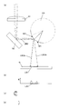
- FIG. 14 is a cross-sectional view of the substrate schematically showing the mechanism by which cracks of finite depth are formed. That is, the preceding laser heating causes a compressive stress HR on the substrate GA as shown in FIG. Subsequently, due to cooling after heating, a tensile stress CR is generated on the substrate surface as shown in FIG. At this time, the compressive stress HR moves inside the substrate due to the movement of heat, and an internal stress field Hin is formed. As a result, as shown in FIG. 14C, a stress gradient in the depth direction in which tensile stress CR is distributed on the substrate surface side and compressive stress HR is distributed inside the substrate is generated, and cracks Cr are formed.
- the compressive stress field Hin existing inside the substrate prevents further penetration of the crack Cr in the depth direction.
- the crack Cr has a finite depth. Therefore, in order to completely divide the substrate, a break process must be further performed after a scribe line having a finite depth by the crack Cr is formed.
- the processed end face of the scribe line by the crack Cr is very beautiful (the surface unevenness is small), and is excellent in straightness, which is an ideal state as the processed end face.
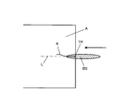
- FIG. 15A and 15B are a perspective view (FIG. 15A) and a plan view (FIG. 15B) schematically showing the mechanism of formation of the through crack, that is, a laser scanned from the position of the initial crack TR.
- the compressive stress HR is generated on the substrate surface by the beam spot BS of the beam, and simultaneously, the tensile stress CR is generated on the substrate surface by the cooling spot CS behind the beam spot BS.
- a stress gradient in the front-rear direction is formed on the scribe line L), and a force that tears the substrate left and right along the scan line direction acts to form a through-crack, thereby dividing the substrate. become.
- this “penetration crack” is formed, it is convenient in that the substrate can be divided (full cut) without performing a break treatment, and depending on the processing application, division by this mechanism may be desired.
- the straightness of the processing end surface of the full cut line may be impaired, and the beauty (surface irregularities) of the end surface of the full cut line is also described above. The quality is inferior compared to the scribe line.
- Whether a scribe line or a full cut line is formed by laser scribe processing depends on heating conditions (laser wavelength, irradiation time, output power, scanning speed, beam spot shape, etc.), cooling conditions (refrigerant temperature, Spray amount, spray position, etc.), board thickness, etc.
- heating conditions laser wavelength, irradiation time, output power, scanning speed, beam spot shape, etc.
- cooling conditions refrigerant temperature, Spray amount, spray position, etc.
- board thickness etc.
- the thickness of the glass substrate is thin, a full cut line is likely to be formed as compared with the case where the glass substrate is thick, and the process window for processing conditions capable of forming a scribe line is narrow.
- a mechanical break treatment in which a bending moment is applied by pressing a break bar or the like against a scribe line may be used.
- cullet may be generated when a large bending moment is applied to the substrate. Therefore, in a manufacturing process that does not like the occurrence of cullet, it is necessary to form a scribe line that is as deep as possible so that the breaking process can be performed only by applying a small bending moment.
- a second laser irradiation is performed along the scribe line formed by laser scribing to penetrate a finite depth crack deeper (in this case, a break treatment is performed again), or the crack is penetrated to the back surface.
- Laser break processing is performed to divide the image (see, for example, Patent Documents 2 to 4). JP 2005-288541 A JP 2001-130921 A JP 2006-256944 A WO2003 / 008352 Publication
- “first run” means that when the initial crack TR formed at the start end is heated by the beam spot BS in the vicinity of the start end of the scribe line L, the heating area by the beam spot BS is the starting point. This is a phenomenon in which a crack K is formed in a direction that cannot be controlled toward the front of the beam spot.
- “first run” occurs, it becomes impossible to form a scribe line along the planned scribe line L, and the straightness of the scribe line is significantly impaired.
- the laser scribing process that performs the first laser irradiation, when the heating and cooling conditions are shifted to more extreme heating and cooling conditions in order to form deep scribe lines, "Occurs more frequently.
- the present invention can stably perform a process of forming a scribe line on a substrate by laser scribe processing and then performing a laser break process to completely divide the substrate or form a deeper scribe line. It is an object of the present invention to provide a method for processing a brittle material substrate. It is another object of the present invention to provide a substrate processing method that can form a deep scribe line or completely divide without causing a “first run” phenomenon. It is another object of the present invention to provide a method for processing a brittle material substrate that can stably perform a cutting process with excellent end surface quality.
- the present invention makes it possible to adjust the energy distribution of a laser spot using a polygon mirror when forming a laser spot using a polygon mirror and performing laser break by scanning this laser spot.
- An object of the present invention is to provide a processing method capable of stable laser breaking by adjusting the energy distribution.
- the processing method of the brittle material substrate of the present invention made to solve the above-mentioned problem is that a laser beam emitted from a laser light source is repeatedly reflected by a polygon mirror that rotates at high speed to form a beam spot on the brittle material substrate.
- a brittle material substrate processing method for processing a substrate by relatively moving the beam spot along a scribe line set on the substrate the following procedure is performed. First, the first beam spot by the first laser irradiation is relatively moved along the scribe line to heat the substrate, and at the same time that the first beam spot has passed, a coolant is sprayed on the part to cool it.
- a laser scribing process is performed in which a stress gradient changing in the depth direction is generated to form a scribe line composed of cracks of a finite depth.
- the heating temperature is always lower than the softening temperature of the substrate so that the substrate does not melt.
- a stress gradient that changes in the depth direction (referred to as a first stress gradient) is generated in the scribe line.
- the first stress gradient is a stress gradient in which tensile stress is distributed on the substrate surface side and compressive stress is distributed on the substrate inner side. Using this first stress gradient, a scribe line composed of cracks of a finite depth is formed.
- the second beam spot by the second laser irradiation is relatively moved along a scribe line (a finite depth crack) to perform a laser break process.
- the laser beam diameter incident on the polygon mirror is adjusted to be smaller than the laser beam diameter incident upon the laser scribing process. Specifically, this adjustment may be performed by reducing the beam diameter of the laser beam itself, or by providing a mechanism for adjusting the beam diameter on the optical path. By this adjustment, the ratio when the laser beam irradiated to the polygon mirror is irradiated to only one mirror surface of the polygon mirror is increased, and when the laser beam is irradiated while being divided by two adjacent mirror surfaces.
- the energy distribution of the second beam spot becomes shorter at both ends where the energy increases and decreases, and the entire length of the second beam spot becomes shorter than the entire length of the first beam spot.
- a top hat type energy distribution having a long central region with uniform energy (detailed in FIG. 11).
- the “top hat type energy distribution” refers to an energy distribution in which the energy at the center of the beam spot is substantially uniform and the energy changes in the regions at both ends of the beam spot.
- a stress gradient (second stress gradient) that changes in the depth direction opposite to the stress gradient (first stress gradient) that changes in the depth direction during laser scribing is formed. That is, compressive stress is generated on the substrate surface, and tensile stress is formed inside the substrate as a reaction.
- the tip of the crack that forms the scribe line exists inside the substrate, but since the tensile stress is concentrated and applied to the tip of the crack, the tip of the crack penetrates deeper and reaches the back of the substrate. Then it becomes completely divided.
- a scribe line (crack of a finite depth) is formed on a substrate by a laser scribe process without forming a full cut line and without causing a “previous run” phenomenon, and then a laser. It is possible to expand a process window that can perform a process of performing a break process to completely cut the substrate or to form a deeper scribe line, thereby realizing a stable process. Further, it is possible to stably perform the cutting process with excellent end face quality of the processed end face. Furthermore, according to the present invention, when a beam spot is formed using a polygon mirror and laser break is performed by scanning the beam spot, the energy distribution of the beam spot can be adjusted using the polygon mirror. it can. Using this, a stable laser break is possible.
- the position of the condensing optical element provided on the optical path of the laser beam between the laser light source and the polygon mirror may be changed to adjust the diameter of the laser beam incident on the polygon mirror.
- a condensing optical element for example, a meniscus lens
- a condensing mirror can be used as the condensing optical element. According to this, it is possible to adjust the laser beam diameter by simply moving the condensing optical element in the optical path direction, and it is easy to adjust the energy distribution to a top hat type with a long central region where the energy is uniform. realizable.
- the polygon mirror may be adjusted to be close to the vicinity of the focal length of the condensing optical element. According to this, the laser beam diameter decreases as the focal distance is approached, so that the polygon mirror can be brought closer to an ideal top hat type.
- the distance between the polygon mirror and the substrate may be adjusted simultaneously with the position of the condensing optical element.
- the energy distribution can be changed to a top-hat type, and the beam shape such as the length of the beam spot in the longitudinal direction can be adjusted, so that the heat input area can be adjusted together with the heat input per unit time.
- the process window of laser break can be further widened.
- substrate processing method of this invention The block diagram which shows the control system of the board
- Sectional drawing which showed typically the stress gradient which is going to be formed in the case of a laser break process.
- Sectional drawing which showed typically the mechanism in which the crack of a finite depth is formed.
- the perspective view and top view which showed typically the mechanism in which a full cut line is formed.
- the figure which shows the advance phenomenon which arises at a board
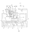
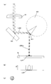
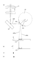
- FIG. 1 is a schematic configuration diagram of a laser cutting device LC1 according to an embodiment of the present invention.
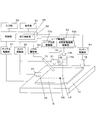
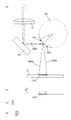
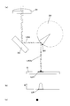
- FIG. 2 is a block diagram showing a configuration of a control system in the laser cutting device LC1 of FIG.
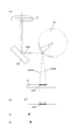
- a slide table 2 that reciprocates in the front-rear direction (hereinafter referred to as the Y direction) in FIG. 1 is provided along a pair of guide rails 3 and 4 arranged in parallel on a horizontal base 1.
- a screw screw 5 is disposed between the guide rails 3 and 4 along the front-rear direction, and a stay 6 fixed to the slide table 2 is screwed to the screw screw 5.
- the slide table 2 is formed to reciprocate in the Y direction along the guide rails 3 and 4 by forward and reverse rotation (not shown).
- a horizontal pedestal 7 is arranged so as to reciprocate in the left-right direction (hereinafter referred to as X direction) in FIG. 1 along the guide rail 8.
- a screw screw 10a rotated by a motor 9 is threaded through a stay 10 fixed to the pedestal 7, and the pedestal 7 is moved along the guide rail 8 in the X direction by rotating the screw screw 10a forward and backward. Move back and forth.
- a rotating table 12 that is rotated by a rotating mechanism 11 is provided on the base 7, and a glass substrate G that is a brittle material substrate to be cut is attached to the rotating table 12 in a horizontal state.
- the rotation mechanism 11 is configured to rotate the rotary table 12 around a vertical axis, and is configured to be rotated at an arbitrary rotation angle with respect to a reference position.
- the glass substrate G is fixed to the rotary table 12 by, for example, a suction chuck.
- a laser oscillator 13 and an optical path adjusting mechanism 14 are held on the mounting frame 15 above the rotary table 12.
- the optical path adjustment mechanism 14 moves the position of an optical path adjustment element group 14a (meniscus lens 31, reflection mirror 32, polygon mirror 33) for adjusting the optical path of laser light emitted from the laser oscillator 13, and the optical path adjustment element group 14a.
- Motor group 14b (motors 34 to 36), and an optical path adjusting element group 14a and an arm group 14c (arms 37 to 39) connecting the motor group 14b.
- the meniscus lens 31 is connected to a lifting motor 34 via an arm 37 so that the vertical position can be adjusted.
- the reflecting mirror 32 is connected to the lifting motor 35 via the arm 38 so that the vertical position can be adjusted.
- the polygon mirror 33 is connected to the lift motor 36 via an arm 39 so that the vertical position can be adjusted.
- the laser beam emitted from the laser oscillator 13 passes through these optical path adjusting element groups 14a, so that a beam bundle having a desired cross-sectional shape is formed and irradiated onto the substrate G as a beam spot.
- a circular laser beam is emitted, the beam diameter is adjusted by the meniscus lens 31, and scanned by the polygon mirror 33, so that a substantially elliptical laser spot LS (FIG. 2) is formed on the glass substrate G. Formed.
- the optical path adjusting element group 14a the first beam spot used in the first laser irradiation (laser scribing process) and the second beam spot spot used in the second laser irradiation (laser breaking process) are switched. Like that.
- adjustment work may be simplified by moving the reflecting mirror 32 and the polygon mirror 33 together. Specifically, the distance between the substrate G and the polygon mirror 33 is adjusted by moving the reflection mirror 32 and the polygon mirror 33 in conjunction with each other, the meniscus lens 31 is moved, and the meniscus lens 31 and the polygon mirror 33 are moved. You may make it perform distance adjustment with.
- the mounting frame 15 is provided with a cooling nozzle 16 adjacent to the optical path adjustment mechanism 14. From the cooling nozzle 16, a cooling medium such as cooling water, He gas, carbon dioxide gas or the like is jetted onto the glass substrate G. The cooling medium is sprayed in the vicinity of the elliptical laser spot LS irradiated on the glass substrate G to form a cooling spot CS (FIG. 2) on the surface of the glass substrate G.
- a cooling medium such as cooling water, He gas, carbon dioxide gas or the like
- the cutter wheel 18 is attached to the attachment frame 15 via the vertical movement adjustment mechanism 17.
- the cutter wheel 18 is made of sintered diamond or cemented carbide, and has a V-shaped ridge line portion with a vertex on the outer peripheral surface, and the pressure contact force to the glass substrate G is a vertical movement adjustment mechanism. 17 can be finely adjusted.
- the cutter wheel 18 is exclusively used when the initial crack TR (FIG. 2) is formed on the edge of the glass substrate G so as to be lowered temporarily while moving the pedestal 7 in the X direction.
- a pair of cameras 20 and 21 are fixed above the mounting frame 15 so that a positioning marker stamped on the substrate G can be projected.
- the laser cutting device LC1 includes a control unit 50 that executes various processes using a control parameter and a program (software) stored in a memory and a CPU.
- the control unit 50 includes a table driving unit 51 that drives a motor (such as the motor 9) for positioning and moving the slide table 2, the pedestal 7, and the rotary table 12, and a laser driving unit 52 (laser oscillator 13) that performs laser irradiation.
- a laser light source driving unit 52a that drives the motor
- an optical path adjusting mechanism driving unit 52b that drives the motor group 14b for the optical path adjusting element group 14a
- an on-off valve (not shown) that controls refrigerant injection by the cooling nozzle 16.
- the nozzle drive unit 53, the cutter wheel 18 and the vertical movement adjustment mechanism 17 form a cutter drive unit 54 that forms an initial crack in the glass substrate G
- the camera drive unit 55 displays a positioning marker stamped on the substrate G by the cameras 20 and 21.
- the control unit 50 is connected to an input unit 56 such as a keyboard and a mouse, and a display unit 57 that performs various displays on the display screen, so that necessary information is displayed on the screen and necessary commands and settings are made. Can be entered.
- control unit 50 comprehensively drives the table driving unit 51, the laser driving unit 52 (laser light source driving unit 52a, the optical path adjustment mechanism driving unit 52b), the nozzle driving unit 53, and the cutter driving unit 54, thereby driving the glass substrate G.
- the processing control unit 58 for performing the above-described processing is provided, and the processing control unit 58 executes laser processing according to the procedure of the first laser irradiation, cooling, and second laser irradiation. Specifically, the processing control unit 58 first controls the cutter driving unit 54 and the table driving unit 51 to move the substrate G while the cutter wheel 18 is lowered, thereby forming the initial crack TR. Is done.
- the table driving unit 51, the laser driving unit 52, and the nozzle driving unit 53 are controlled to move the substrate G while irradiating the laser beam (first beam spot) and injecting the coolant.
- the first laser irradiation and cooling are performed, and a process of forming a scribe line composed of cracks of a finite depth on the substrate is performed.
- the table driving unit 51 and the laser driving unit 52 are controlled to move the substrate G in a state where the laser beam (second beam spot) is irradiated.
- a second laser irradiation is performed, and a process of penetrating cracks (or a process of complete division) is performed.
- FIG. 3 is a diagram showing an example of the operation of the optical path adjusting mechanism 14. Specifically, the beam diameter irradiated to the mirror surface of the polygon mirror 33 is changed by the vertical movement of the meniscus lens 31, and the substrate G is irradiated. It is a figure explaining the operation
- the traveling direction of the laser beam LB0 having a circular cross section emitted from the laser light source 13 is directed vertically downward, and the laser beam LB0 enters the meniscus lens 31.
- the laser beam LB1 that has passed through the meniscus lens 31 further proceeds in the vertical direction while being condensed, and enters the reflection mirror 32.
- the incident angle of 45 degrees is incident on the reflecting surface of the reflecting mirror 32, and the mounting angle of the reflecting mirror 32 is adjusted so as to be emitted at the reflecting angle of 45 degrees, and the laser beam LB2 reflected by the reflecting mirror 32 is adjusted. Advances horizontally.
- the laser beam LB2 traveling in the horizontal direction is incident on the rotating polygon mirror 33.
- the beam diameter irradiated on the mirror surface of the polygon mirror changes according to the distance between the meniscus lens 31 and the polygon mirror 33.
- FIGS. 4 to 6 are diagrams showing the relationship between the rotation angle of the polygon mirror, the optical path of the laser beam, and the beam spot when the beam diameter irradiated onto the mirror surface of the polygon mirror 33 is relatively large.
- the beam diameter in this state is realized when the meniscus lens 31 is brought close to the reflection mirror 32 and adjusted so that the focus of the meniscus lens 31 is closer to the substrate G than the mirror surface of the polygon mirror 33.
- the beam diameter in this state is used in the laser scribing process.
- FIG. 4A attention is paid to the two mirror surfaces M0 and M1 of the polygon mirror 33 rotating in the clockwise direction.
- the mirror surface M0 is a mirror surface to which the laser beam LB2 has been irradiated until just before.
- the laser beam LB2 is divided and irradiated simultaneously at the end of the mirror surface M0 and the start of the next mirror surface M1.
- FIG. 4C is a diagram showing a cross-sectional shape of the laser beam LB2 irradiated on the mirror surface M0.
- FIG. 4D shows a cross-sectional shape of the laser beam LB2 irradiated on the mirror surface M1.
- the energy of the laser beam applied to the mirror surfaces M0 and M1 is distributed according to the area ratio of the cross sections of the divided laser beams.
- the laser beam LB3a reflected on the mirror surface M0 side irradiates the left end portion of the position of the beam spot LS1 on the glass substrate G, and gives energy to this portion.
- the laser beam LB3b reflected on the mirror surface M1 side irradiates the right end portion of the position of the beam spot LS1, and gives energy to this portion.
- FIG. 4B shows the energy distribution applied to the position of the beam spot LS1 on the substrate G.
- FIG. 5A shows a state in which the rotation further proceeds and the laser beam LB2 is irradiated on the central portion of the mirror surface M1. At this point, only one mirror surface M1 is irradiated with the laser beam LB2 having a circular cross section.
- FIG. 5C is a diagram showing a cross-sectional shape of the laser beam LB2 irradiated on the mirror surface M1. The beam having a circular cross section included in the laser beam LB2 is irradiated as it is. At this time, the laser beam LB3c reflected by the mirror surface M1 irradiates the center of the position of the beam spot LS1, and gives all energy to this portion.
- FIG. 5B shows the energy distribution irradiated to the position of the beam spot LS1 on the substrate G. Energy is applied to the central portion of the position of the beam spot LS1, and this portion is heated intensively.
- FIG. 6 shows a state in which the rotation further proceeds, and the laser beam LB2 is split and irradiated at the end of the mirror surface M1 and the start of the next mirror surface M2.
- FIG. 6C is a diagram showing a cross-sectional shape of the laser beam LB2 irradiated on the mirror surface M1.
- FIG. 6D is a diagram showing a cross-sectional shape of the laser beam LB2 irradiated on the mirror surface M2.
- the energy of the laser beam applied to the mirror surfaces M1 and M2 is distributed according to the area ratio of the cross sections of the divided laser beams.
- the laser beam LB3d reflected on the mirror surface M1 side irradiates the left end portion of the position of the beam spot LS1 on the glass substrate G, and gives energy to this portion.
- the laser beam LB3e reflected on the mirror surface M2 side irradiates the right end portion of the position of the beam spot LS1, and gives energy to this portion.
- FIG. 6B shows the energy distribution applied to the position of the beam spot LS1 on the substrate G.
- the energy applied to the substrate G is distributed in two, and both ends of the beam spot LS1 are heated with energy corresponding to the division ratio.
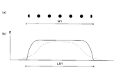
- FIG. 7 is a diagram showing the relationship between the temporal change in the cross-sectional shape of the laser beam LB2 irradiated on the mirror surface M1 rotating at high speed and the energy distribution of the beam spot LS1 irradiated on the glass substrate G by the mirror surface M1.
- the cross section of the laser beam LB2 irradiated on the mirror surface M1 changes as the rotation proceeds. That is, during the period when the start end of the mirror surface M1 (boundary with the mirror surface M0) passes through the irradiation range of the laser beam LB2, the cross-sectional shape of the laser beam LB2 irradiated on the mirror surface M1 is a part of a circular cross section.
- the cross-sectional shape of the laser beam LB2 irradiated on the mirror surface M1 becomes a circular cross-section, and the circular cross-section continues until the end of the mirror surface M1 (boundary with the mirror surface M2) enters the irradiation range of the laser beam LB2. .
- the cross-sectional shape of the laser beam LB2 irradiated to the mirror surface M1 becomes a cross-sectional shape in which a part of the circular cross-section is lost again. The area gradually decreases.
- the energy distribution of the beam spot LS1 is an energy distribution in which the energy at the center is uniform (top hat type), and both ends thereof change gently.
- the width of the gentle portions at both ends corresponds to the range in which the laser beam reflected by the mirror surface M1 is irradiated on the substrate G during the period when the start or end of the mirror surface M1 passes through the irradiation range of the laser beam LB2. . Therefore, as the beam diameter of the laser beam LB2 increases, the width of the portion where the energy distribution at both ends of the beam spot LS1 changes gently increases. Then, irradiation with the energy distribution of FIG. 7B is repeated by each mirror surface of the rotating polygon mirror 33.
- 8 to 10 are diagrams showing the relationship between the rotation angle of the polygon mirror, the optical path of the laser beam, and the beam spot when the beam diameter of the laser beam LB2 irradiated on the mirror surface is relatively small.
- the beam diameter in this state is realized when the position of the meniscus lens 31 is adjusted so that the focus of the meniscus lens 31 is in the vicinity of the mirror surface M1 of the polygon mirror 33.
- the beam diameter in this state is used in the laser break process.
- FIG. 8A As in FIG. 4A, attention is paid to the two mirror surfaces M0 and M1 of the polygon mirror 33 rotating in the clockwise direction.
- the mirror surface M0 is a mirror surface that has been irradiated with the laser beam LB2 immediately before.
- the laser beam LB2 is divided and irradiated simultaneously at the end of the mirror surface M0 and the start of the next mirror surface M1.
- FIG. 8C is a diagram showing a cross-sectional shape of the laser beam LB2 irradiated on the mirror surface M0.
- the 8D shows a cross-sectional shape of the laser beam LB2 irradiated on the mirror surface M1. Since the beam diameter is small, the range in which the two mirror surfaces M0 and M1 are simultaneously irradiated (the range from the start end and the end to the beam diameter) is narrower than in the case of FIG.
- the energy of the laser beam applied to the mirror surfaces M0 and M1 is distributed according to the area ratio of the divided beams as in FIG.
- the laser beam LB3a reflected on the mirror surface M0 side irradiates the left end portion of the position of the beam spot LS1 on the glass substrate G, and gives energy to this portion.
- the laser beam LB3b reflected on the mirror surface M1 side irradiates the right end portion of the position of the beam spot LS1, and gives energy to this portion.
- FIG. 8B shows the energy distribution applied to the position of the beam spot LS1 on the substrate G.
- FIG. 9A shows a state in which the rotation further proceeds, and the central portion of the mirror surface M1 is irradiated with the laser beam LB2. At this point, only one mirror surface M1 is irradiated with the laser beam LB2 having a circular cross section.
- FIG. 9C shows a cross-sectional shape of the laser beam LB2 irradiated on the mirror surface M1. The beam having a circular cross section included in the laser beam LB2 is irradiated as it is. At this time, the laser beam LB3c reflected by the mirror surface M1 irradiates the center of the position of the beam spot LS1, and gives all energy to this portion.
- FIG. 9B shows the energy distribution applied to the position of the beam spot LS1 on the substrate G at this time. Energy is applied to the central portion of the position of the beam spot LS1, and this portion is heated intensively.
- FIG. 10 shows a state in which the rotation further proceeds and the laser beam LB2 is divided and irradiated at the end of the mirror surface M1 and the start end of the next mirror surface M2.
- FIG. 10C is a diagram showing a cross-sectional shape of the laser beam LB2 irradiated on the mirror surface M1.
- FIG. 10D is a diagram showing a cross-sectional shape of the laser beam LB2 irradiated on the mirror surface M2. Similar to FIG. 6, the energy of the laser beam applied to the mirror surfaces M ⁇ b> 1 and M ⁇ b> 2 is distributed according to the area ratio of the cross sections of the divided laser beams.
- the laser beam LB3d reflected on the mirror surface M1 side irradiates the left end portion of the position of the beam spot LS1 on the glass substrate G, and gives energy to this portion.
- the laser beam LB3e reflected on the mirror surface M2 side irradiates the right end portion of the position of the beam spot LS1, and gives energy to this portion.
- FIG. 10B shows the energy distribution applied to the position of the beam spot LS1 on the substrate G at this time.
- the energy applied to the substrate G is distributed in two, and both ends of the beam spot LS1 are heated with energy corresponding to the division ratio.
- FIG. 11 is a diagram showing the relationship between the temporal change of the cross-sectional shape of the laser beam LB2 irradiated to the mirror surface M1 rotating at high speed and the energy distribution of the beam spot LS1 irradiated to the glass substrate G by the mirror surface M1.
- the entire cross-sectional area irradiated is larger than that when the beam diameter shown in FIG. However, the energy density is high. Furthermore, as shown in FIG. 11A, the cross section of the laser beam LB2 irradiated on the mirror surface M1 changes as the rotation proceeds. That is, similarly to FIG. 7A, the period during which the start end of the mirror surface M1 (boundary with the mirror surface M0) passes through the irradiation range of the laser beam LB2, and the end of the mirror surface M1 (boundary with the mirror surface M2).
- the cross section of the laser beam LB2 applied to the mirror surface M1 has a cross-sectional shape with a part of a circular cross section missing, and the cross-sectional area increases within this range. Or decrease.
- the cross section of the laser beam LB2 irradiated on the mirror surface M1 is a circular cross section.
- the width of the range in which the cross-sectional area of the laser beam LB2 irradiated to the mirror surface M1 changes near the start end and the end of the mirror surface M1 is narrower than that in FIG.
- the cross-sectional area increases or decreases rapidly.
- the energy distribution of the beam spot LS1 formed on the substrate G by the mirror surface M1 changes.
- the energy distribution of the beam spot LS1 at this time is shown in FIG.
- the energy distribution when the beam diameter is small is indicated by a solid line
- the energy distribution when the beam diameter is large is indicated by a one-dot chain line.
- the energy distribution of the beam spot LS1 becomes shorter at both ends where the energy changes, the overall length of the beam spot LS1 becomes shorter, and the central portion where the energy is uniform.
- This region has a long top hat type energy distribution.
- irradiation is repeated with a beam spot LS1 having an energy distribution similar to that of the mirror surface M1 by each mirror surface of the rotating polygon mirror 33.
- the energy distribution of the beam spot can be adjusted only by adjusting the height of the meniscus lens 31.
- the energy distribution of the beam spot irradiated on the substrate G can be adjusted.
- the length of the entire beam spot also changes. Therefore, when it is not desired to change the major axis length of the beam spot from process to process, or conversely, when it is desired to further adjust the length of the major axis in the laser break process, the meniscus lens 31 and the polygon mirror 33 At the same time as adjusting the distance, the polygon mirror 33 and the reflecting mirror 32 are moved together to adjust the distance to the substrate G, and the major axis length is also adjusted. Thus, heating is performed with a desired beam spot shape and a desired energy distribution.
- FIG. 12 is a cross-sectional view schematically showing a stress gradient to be formed in the laser breaking process by the processing method of the present invention.
- the beam spot is made into a top hat type energy distribution and heated from the substrate surface layer in a short time to form a heating region H. Then, a large compressive stress HR is formed on the surface layer of the substrate, and a tensile stress CR is generated inside the substrate in response to the influence.
- the crack Cr generated by the immediately preceding laser scribing process is present inside the substrate, the tensile stress is concentrated at the tip of the crack Cr, and as a result, the crack Cr penetrates deeper. Further, when the crack Cr reaches the back surface, it is completely divided.
- FIG. 13 is a flowchart of the processing procedure.
- the substrate G is placed on the turntable 12 and fixed by a suction chuck.
- the rotary table 12 is moved under the cameras 20 and 21, and an alignment mark (not shown) engraved on the glass substrate A is detected by the cameras 20 and 21. Based on the detection result, the relationship between the position of the scheduled scribe line and the rotary table 12, the slide table 2, and the base 7 is stored.
- the rotary table 12 and the slide table 2 are operated so that the cutting edge direction of the cutter wheel 18 is aligned with the direction of the scribe line, and the cutting edge is positioned near the position where the initial crack is formed (S101).
- the position at this time is stored as a machining start position.
- the lifting mechanism 17 is operated to lower the cutter wheel 18.
- the rotary table 12 (pedestal 7) is moved to press-contact the substrate end cutter wheel 18. Thereby, the initial crack TR is formed.
- the lifting mechanism 17 is operated to raise the cutter wheel 18 (S102).
- the substrate G is returned to the processing start position, and the laser device 13 is operated to irradiate the first laser beam.
- the position of the meniscus lens 31 is adjusted, and the light enters the mirror surface of the polygon mirror 31 with a relatively large beam diameter (see FIGS. 4 to 7).
- the coolant is injected from the cooling nozzle 16.
- the rotary table 12 base 7) is moved to scan the beam spot and the cooling spot along the scheduled scribe line, thereby forming a scribe line (S103).
- the substrate G is returned to the processing start position, and the second laser beam is irradiated.
- the position of the meniscus lens 31 is further away from the reflection mirror 32 than during the first irradiation, and the diameter of the beam incident on the mirror surface of the polygon mirror 33 is narrowed down (see FIGS. 8 to 11).
- the cooling nozzle 16 may continue to inject, but it is not always necessary, so it stops here.
- the rotary table 12 base 7) is moved, and a beam spot having a top hat type energy distribution is scanned along the scribe line formed in the previous scan.
- the cracks forming the scribe line penetrate deeply and are completely divided when reaching the back surface of the substrate (S104).
- the scribe line formed in this way has a very excellent processed cross section, and the end face strength is also increased.
- the present invention can be used for a process of forming a deep scribe line or completely dividing a brittle material substrate such as a glass substrate.
Landscapes
- Engineering & Computer Science (AREA)
- Chemical & Material Sciences (AREA)
- Physics & Mathematics (AREA)
- Optics & Photonics (AREA)
- Materials Engineering (AREA)
- Organic Chemistry (AREA)
- Mechanical Engineering (AREA)
- Health & Medical Sciences (AREA)
- Toxicology (AREA)
- Plasma & Fusion (AREA)
- Mining & Mineral Resources (AREA)
- Thermal Sciences (AREA)
- Re-Forming, After-Treatment, Cutting And Transporting Of Glass Products (AREA)
- Laser Beam Processing (AREA)
- Processing Of Stones Or Stones Resemblance Materials (AREA)
Priority Applications (3)
| Application Number | Priority Date | Filing Date | Title |
|---|---|---|---|
| CN200980119186XA CN102046345A (zh) | 2008-04-15 | 2009-03-16 | 脆性材料基板的加工方法 |
| JP2010508155A JP5050099B2 (ja) | 2008-04-15 | 2009-03-16 | 脆性材料基板の加工方法 |
| KR1020107025336A KR101165977B1 (ko) | 2008-04-15 | 2009-03-16 | 취성 재료 기판의 가공 방법 |
Applications Claiming Priority (2)
| Application Number | Priority Date | Filing Date | Title |
|---|---|---|---|
| JP2008106219 | 2008-04-15 | ||
| JP2008-106219 | 2008-04-15 |
Publications (1)
| Publication Number | Publication Date |
|---|---|
| WO2009128316A1 true WO2009128316A1 (ja) | 2009-10-22 |
Family
ID=41199016
Family Applications (1)
| Application Number | Title | Priority Date | Filing Date |
|---|---|---|---|
| PCT/JP2009/055061 WO2009128316A1 (ja) | 2008-04-15 | 2009-03-16 | 脆性材料基板の加工方法 |
Country Status (5)
| Country | Link |
|---|---|
| JP (1) | JP5050099B2 (ko) |
| KR (1) | KR101165977B1 (ko) |
| CN (1) | CN102046345A (ko) |
| TW (1) | TW200948524A (ko) |
| WO (1) | WO2009128316A1 (ko) |
Cited By (3)
| Publication number | Priority date | Publication date | Assignee | Title |
|---|---|---|---|---|
| KR101388181B1 (ko) | 2012-09-04 | 2014-04-30 | (주)하드램 | 유리 기판 레이저 절단 장치 및 방법 |
| WO2014157245A1 (ja) * | 2013-03-26 | 2014-10-02 | 旭硝子株式会社 | ガラス板の加工方法、およびガラス板の加工装置 |
| CN109148260A (zh) * | 2017-06-19 | 2019-01-04 | 胜高股份有限公司 | 激光标记的刻印方法、带激光标记的硅晶片及其制造方法 |
Families Citing this family (9)
| Publication number | Priority date | Publication date | Assignee | Title |
|---|---|---|---|---|
| JP5879106B2 (ja) * | 2011-11-25 | 2016-03-08 | 三星ダイヤモンド工業株式会社 | 脆性材料基板のスクライブ方法 |
| JP2013136074A (ja) * | 2011-12-28 | 2013-07-11 | Mitsuboshi Diamond Industrial Co Ltd | 分断装置、被加工物の分断方法、および光学素子パターン付き基板の分断方法 |
| TWI562264B (en) * | 2012-12-19 | 2016-12-11 | Genesis Photonics Inc | Splitting apparatus and splitting method |
| TWM469728U (zh) * | 2013-05-30 | 2014-01-01 | Bungbungame Inc | 承載架及運用此承載架的包裝盒 |
| JP6413693B2 (ja) * | 2014-11-25 | 2018-10-31 | 三星ダイヤモンド工業株式会社 | 脆性基板の分断方法 |
| CN105436712B (zh) * | 2015-12-07 | 2017-12-12 | 武汉铱科赛科技有限公司 | 一种脆性半导体材料的脆性裂片方法及系统 |
| CN105436617B (zh) * | 2016-01-13 | 2017-05-31 | 中国工程物理研究院核物理与化学研究所 | 同位素辐照盒无屑切割机 |
| JP6888808B2 (ja) * | 2017-03-30 | 2021-06-16 | 三星ダイヤモンド工業株式会社 | 樹脂層付き脆性材料基板の分断方法並びに分断装置 |
| JP6717353B2 (ja) * | 2018-10-22 | 2020-07-01 | 株式会社Sumco | レーザマーク付きシリコンウェーハの製造方法 |
Citations (2)
| Publication number | Priority date | Publication date | Assignee | Title |
|---|---|---|---|---|
| JP2001130921A (ja) * | 1999-10-29 | 2001-05-15 | Mitsuboshi Diamond Industrial Co Ltd | 脆性基板の加工方法及び装置 |
| JP2005288541A (ja) * | 2004-03-31 | 2005-10-20 | Eo Technics Co Ltd | ポリゴンミラーを利用するレーザ加工装置 |
-
2009
- 2009-03-16 WO PCT/JP2009/055061 patent/WO2009128316A1/ja active Application Filing
- 2009-03-16 CN CN200980119186XA patent/CN102046345A/zh active Pending
- 2009-03-16 JP JP2010508155A patent/JP5050099B2/ja not_active Expired - Fee Related
- 2009-03-16 KR KR1020107025336A patent/KR101165977B1/ko not_active IP Right Cessation
- 2009-04-06 TW TW098111342A patent/TW200948524A/zh not_active IP Right Cessation
Patent Citations (2)
| Publication number | Priority date | Publication date | Assignee | Title |
|---|---|---|---|---|
| JP2001130921A (ja) * | 1999-10-29 | 2001-05-15 | Mitsuboshi Diamond Industrial Co Ltd | 脆性基板の加工方法及び装置 |
| JP2005288541A (ja) * | 2004-03-31 | 2005-10-20 | Eo Technics Co Ltd | ポリゴンミラーを利用するレーザ加工装置 |
Cited By (6)
| Publication number | Priority date | Publication date | Assignee | Title |
|---|---|---|---|---|
| KR101388181B1 (ko) | 2012-09-04 | 2014-04-30 | (주)하드램 | 유리 기판 레이저 절단 장치 및 방법 |
| WO2014157245A1 (ja) * | 2013-03-26 | 2014-10-02 | 旭硝子株式会社 | ガラス板の加工方法、およびガラス板の加工装置 |
| JPWO2014157245A1 (ja) * | 2013-03-26 | 2017-02-16 | 旭硝子株式会社 | ガラス板の加工方法、およびガラス板の加工装置 |
| US10450216B2 (en) | 2013-03-26 | 2019-10-22 | AGC Inc. | Glass sheet processing method and glass sheet processing apparatus |
| CN109148260A (zh) * | 2017-06-19 | 2019-01-04 | 胜高股份有限公司 | 激光标记的刻印方法、带激光标记的硅晶片及其制造方法 |
| CN109148260B (zh) * | 2017-06-19 | 2023-04-25 | 胜高股份有限公司 | 激光标记的刻印方法、带激光标记的硅晶片及其制造方法 |
Also Published As
| Publication number | Publication date |
|---|---|
| KR20110006678A (ko) | 2011-01-20 |
| TW200948524A (en) | 2009-12-01 |
| CN102046345A (zh) | 2011-05-04 |
| JPWO2009128316A1 (ja) | 2011-08-04 |
| KR101165977B1 (ko) | 2012-07-18 |
| JP5050099B2 (ja) | 2012-10-17 |
| TWI375602B (ko) | 2012-11-01 |
Similar Documents
| Publication | Publication Date | Title |
|---|---|---|
| JP5050099B2 (ja) | 脆性材料基板の加工方法 | |
| JP5060880B2 (ja) | 脆性材料基板の分断装置および分断方法 | |
| JP5325209B2 (ja) | 脆性材料基板の加工方法 | |
| KR101193872B1 (ko) | 취성재료기판의 챔퍼링 방법 | |
| JP5345334B2 (ja) | 脆性材料の熱応力割断方法 | |
| JP5314674B2 (ja) | 脆性材料基板の加工方法 | |
| WO2010090111A1 (ja) | 加工対象物切断方法 | |
| JP2008503355A (ja) | 基板材料の切断、分断または分割装置、システムおよび方法 | |
| TW200920534A (en) | Method for cutting a fragile material substrate | |
| KR20100087371A (ko) | 취성 재료 기판의 모따기 가공 방법 및 모따기 가공 장치 | |
| KR101306673B1 (ko) | 모따기 가공 장치 | |
| WO2009128315A1 (ja) | 脆性材料基板の加工方法 | |
| JP2011230940A (ja) | 脆性材料基板の割断方法 | |
| KR100647454B1 (ko) | 취성재료 기판의 스크라이브 장치 및 스크라이브 방법 | |
| JPWO2003008352A1 (ja) | 脆性材料基板のスクライブ装置およびスクライブ方法 | |
| JP2005212364A (ja) | 脆性材料の割断加工システム及びその方法 | |
| JP5590642B2 (ja) | スクライブ加工装置及びスクライブ加工方法 | |
| JPWO2003013816A1 (ja) | 脆性材料基板のスクライブ方法およびスクライブ装置 | |
| JP5560096B2 (ja) | レーザ加工方法 |
Legal Events
| Date | Code | Title | Description |
|---|---|---|---|
| WWE | Wipo information: entry into national phase |
Ref document number: 200980119186.X Country of ref document: CN |
|
| 121 | Ep: the epo has been informed by wipo that ep was designated in this application |
Ref document number: 09732220 Country of ref document: EP Kind code of ref document: A1 |
|
| WWE | Wipo information: entry into national phase |
Ref document number: 2010508155 Country of ref document: JP |
|
| NENP | Non-entry into the national phase |
Ref country code: DE |
|
| ENP | Entry into the national phase |
Ref document number: 20107025336 Country of ref document: KR Kind code of ref document: A |
|
| 122 | Ep: pct application non-entry in european phase |
Ref document number: 09732220 Country of ref document: EP Kind code of ref document: A1 |