WO2009116505A1 - 溶融樹脂供給方法、溶融樹脂供給装置、溶融樹脂圧縮成形方法、溶融樹脂圧縮成形装置、及び合成樹脂製容器の製造方法 - Google Patents
溶融樹脂供給方法、溶融樹脂供給装置、溶融樹脂圧縮成形方法、溶融樹脂圧縮成形装置、及び合成樹脂製容器の製造方法 Download PDFInfo
- Publication number
- WO2009116505A1 WO2009116505A1 PCT/JP2009/055089 JP2009055089W WO2009116505A1 WO 2009116505 A1 WO2009116505 A1 WO 2009116505A1 JP 2009055089 W JP2009055089 W JP 2009055089W WO 2009116505 A1 WO2009116505 A1 WO 2009116505A1
- Authority
- WO
- WIPO (PCT)
- Prior art keywords
- molten resin
- compression molding
- extrusion port
- cut
- mold
- Prior art date
Links
Images


Classifications
-
- B—PERFORMING OPERATIONS; TRANSPORTING
- B29—WORKING OF PLASTICS; WORKING OF SUBSTANCES IN A PLASTIC STATE IN GENERAL
- B29C—SHAPING OR JOINING OF PLASTICS; SHAPING OF MATERIAL IN A PLASTIC STATE, NOT OTHERWISE PROVIDED FOR; AFTER-TREATMENT OF THE SHAPED PRODUCTS, e.g. REPAIRING
- B29C43/00—Compression moulding, i.e. applying external pressure to flow the moulding material; Apparatus therefor
- B29C43/32—Component parts, details or accessories; Auxiliary operations
- B29C43/34—Feeding the material to the mould or the compression means
-
- B—PERFORMING OPERATIONS; TRANSPORTING
- B29—WORKING OF PLASTICS; WORKING OF SUBSTANCES IN A PLASTIC STATE IN GENERAL
- B29B—PREPARATION OR PRETREATMENT OF THE MATERIAL TO BE SHAPED; MAKING GRANULES OR PREFORMS; RECOVERY OF PLASTICS OR OTHER CONSTITUENTS OF WASTE MATERIAL CONTAINING PLASTICS
- B29B11/00—Making preforms
- B29B11/06—Making preforms by moulding the material
- B29B11/12—Compression moulding
-
- B—PERFORMING OPERATIONS; TRANSPORTING
- B29—WORKING OF PLASTICS; WORKING OF SUBSTANCES IN A PLASTIC STATE IN GENERAL
- B29C—SHAPING OR JOINING OF PLASTICS; SHAPING OF MATERIAL IN A PLASTIC STATE, NOT OTHERWISE PROVIDED FOR; AFTER-TREATMENT OF THE SHAPED PRODUCTS, e.g. REPAIRING
- B29C31/00—Handling, e.g. feeding of the material to be shaped, storage of plastics material before moulding; Automation, i.e. automated handling lines in plastics processing plants, e.g. using manipulators or robots
- B29C31/04—Feeding of the material to be moulded, e.g. into a mould cavity
- B29C31/042—Feeding of the material to be moulded, e.g. into a mould cavity using dispensing heads, e.g. extruders, placed over or apart from the moulds
- B29C31/048—Feeding of the material to be moulded, e.g. into a mould cavity using dispensing heads, e.g. extruders, placed over or apart from the moulds the material being severed at the dispensing head exit, e.g. as ring, drop or gob, and transported immediately into the mould, e.g. by gravity
-
- B—PERFORMING OPERATIONS; TRANSPORTING
- B29—WORKING OF PLASTICS; WORKING OF SUBSTANCES IN A PLASTIC STATE IN GENERAL
- B29C—SHAPING OR JOINING OF PLASTICS; SHAPING OF MATERIAL IN A PLASTIC STATE, NOT OTHERWISE PROVIDED FOR; AFTER-TREATMENT OF THE SHAPED PRODUCTS, e.g. REPAIRING
- B29C43/00—Compression moulding, i.e. applying external pressure to flow the moulding material; Apparatus therefor
- B29C43/02—Compression moulding, i.e. applying external pressure to flow the moulding material; Apparatus therefor of articles of definite length, i.e. discrete articles
- B29C43/04—Compression moulding, i.e. applying external pressure to flow the moulding material; Apparatus therefor of articles of definite length, i.e. discrete articles using movable moulds
- B29C43/06—Compression moulding, i.e. applying external pressure to flow the moulding material; Apparatus therefor of articles of definite length, i.e. discrete articles using movable moulds continuously movable in one direction, e.g. mounted on chains, belts
- B29C43/08—Compression moulding, i.e. applying external pressure to flow the moulding material; Apparatus therefor of articles of definite length, i.e. discrete articles using movable moulds continuously movable in one direction, e.g. mounted on chains, belts with circular movement, e.g. mounted on rolls, turntables
-
- B—PERFORMING OPERATIONS; TRANSPORTING
- B29—WORKING OF PLASTICS; WORKING OF SUBSTANCES IN A PLASTIC STATE IN GENERAL
- B29C—SHAPING OR JOINING OF PLASTICS; SHAPING OF MATERIAL IN A PLASTIC STATE, NOT OTHERWISE PROVIDED FOR; AFTER-TREATMENT OF THE SHAPED PRODUCTS, e.g. REPAIRING
- B29C43/00—Compression moulding, i.e. applying external pressure to flow the moulding material; Apparatus therefor
- B29C43/02—Compression moulding, i.e. applying external pressure to flow the moulding material; Apparatus therefor of articles of definite length, i.e. discrete articles
- B29C43/20—Making multilayered or multicoloured articles
- B29C43/203—Making multilayered articles
-
- B—PERFORMING OPERATIONS; TRANSPORTING
- B29—WORKING OF PLASTICS; WORKING OF SUBSTANCES IN A PLASTIC STATE IN GENERAL
- B29C—SHAPING OR JOINING OF PLASTICS; SHAPING OF MATERIAL IN A PLASTIC STATE, NOT OTHERWISE PROVIDED FOR; AFTER-TREATMENT OF THE SHAPED PRODUCTS, e.g. REPAIRING
- B29C48/00—Extrusion moulding, i.e. expressing the moulding material through a die or nozzle which imparts the desired form; Apparatus therefor
- B29C48/03—Extrusion moulding, i.e. expressing the moulding material through a die or nozzle which imparts the desired form; Apparatus therefor characterised by the shape of the extruded material at extrusion
- B29C48/09—Articles with cross-sections having partially or fully enclosed cavities, e.g. pipes or channels
- B29C48/10—Articles with cross-sections having partially or fully enclosed cavities, e.g. pipes or channels flexible, e.g. blown foils
-
- B—PERFORMING OPERATIONS; TRANSPORTING
- B29—WORKING OF PLASTICS; WORKING OF SUBSTANCES IN A PLASTIC STATE IN GENERAL
- B29C—SHAPING OR JOINING OF PLASTICS; SHAPING OF MATERIAL IN A PLASTIC STATE, NOT OTHERWISE PROVIDED FOR; AFTER-TREATMENT OF THE SHAPED PRODUCTS, e.g. REPAIRING
- B29C43/00—Compression moulding, i.e. applying external pressure to flow the moulding material; Apparatus therefor
- B29C43/32—Component parts, details or accessories; Auxiliary operations
- B29C43/34—Feeding the material to the mould or the compression means
- B29C2043/3405—Feeding the material to the mould or the compression means using carrying means
- B29C2043/3411—Feeding the material to the mould or the compression means using carrying means mounted onto arms, e.g. grippers, fingers, clamping frame, suction means
-
- B—PERFORMING OPERATIONS; TRANSPORTING
- B29—WORKING OF PLASTICS; WORKING OF SUBSTANCES IN A PLASTIC STATE IN GENERAL
- B29C—SHAPING OR JOINING OF PLASTICS; SHAPING OF MATERIAL IN A PLASTIC STATE, NOT OTHERWISE PROVIDED FOR; AFTER-TREATMENT OF THE SHAPED PRODUCTS, e.g. REPAIRING
- B29C43/00—Compression moulding, i.e. applying external pressure to flow the moulding material; Apparatus therefor
- B29C43/32—Component parts, details or accessories; Auxiliary operations
- B29C43/34—Feeding the material to the mould or the compression means
- B29C2043/3433—Feeding the material to the mould or the compression means using dispensing heads, e.g. extruders, placed over or apart from the moulds
-
- B—PERFORMING OPERATIONS; TRANSPORTING
- B29—WORKING OF PLASTICS; WORKING OF SUBSTANCES IN A PLASTIC STATE IN GENERAL
- B29C—SHAPING OR JOINING OF PLASTICS; SHAPING OF MATERIAL IN A PLASTIC STATE, NOT OTHERWISE PROVIDED FOR; AFTER-TREATMENT OF THE SHAPED PRODUCTS, e.g. REPAIRING
- B29C43/00—Compression moulding, i.e. applying external pressure to flow the moulding material; Apparatus therefor
- B29C43/32—Component parts, details or accessories; Auxiliary operations
- B29C43/34—Feeding the material to the mould or the compression means
- B29C2043/3466—Feeding the material to the mould or the compression means using rotating supports, e.g. turntables or drums
-
- B—PERFORMING OPERATIONS; TRANSPORTING
- B29—WORKING OF PLASTICS; WORKING OF SUBSTANCES IN A PLASTIC STATE IN GENERAL
- B29C—SHAPING OR JOINING OF PLASTICS; SHAPING OF MATERIAL IN A PLASTIC STATE, NOT OTHERWISE PROVIDED FOR; AFTER-TREATMENT OF THE SHAPED PRODUCTS, e.g. REPAIRING
- B29C2793/00—Shaping techniques involving a cutting or machining operation
- B29C2793/009—Shaping techniques involving a cutting or machining operation after shaping
-
- B—PERFORMING OPERATIONS; TRANSPORTING
- B29—WORKING OF PLASTICS; WORKING OF SUBSTANCES IN A PLASTIC STATE IN GENERAL
- B29C—SHAPING OR JOINING OF PLASTICS; SHAPING OF MATERIAL IN A PLASTIC STATE, NOT OTHERWISE PROVIDED FOR; AFTER-TREATMENT OF THE SHAPED PRODUCTS, e.g. REPAIRING
- B29C31/00—Handling, e.g. feeding of the material to be shaped, storage of plastics material before moulding; Automation, i.e. automated handling lines in plastics processing plants, e.g. using manipulators or robots
- B29C31/04—Feeding of the material to be moulded, e.g. into a mould cavity
- B29C31/10—Feeding of the material to be moulded, e.g. into a mould cavity of several materials
-
- B—PERFORMING OPERATIONS; TRANSPORTING
- B29—WORKING OF PLASTICS; WORKING OF SUBSTANCES IN A PLASTIC STATE IN GENERAL
- B29C—SHAPING OR JOINING OF PLASTICS; SHAPING OF MATERIAL IN A PLASTIC STATE, NOT OTHERWISE PROVIDED FOR; AFTER-TREATMENT OF THE SHAPED PRODUCTS, e.g. REPAIRING
- B29C48/00—Extrusion moulding, i.e. expressing the moulding material through a die or nozzle which imparts the desired form; Apparatus therefor
- B29C48/16—Articles comprising two or more components, e.g. co-extruded layers
- B29C48/18—Articles comprising two or more components, e.g. co-extruded layers the components being layers
-
- B—PERFORMING OPERATIONS; TRANSPORTING
- B29—WORKING OF PLASTICS; WORKING OF SUBSTANCES IN A PLASTIC STATE IN GENERAL
- B29L—INDEXING SCHEME ASSOCIATED WITH SUBCLASS B29C, RELATING TO PARTICULAR ARTICLES
- B29L2031/00—Other particular articles
- B29L2031/712—Containers; Packaging elements or accessories, Packages
Definitions
- the present invention relates to a molten resin supply method for cutting a molten resin extruded from an extruder into a predetermined length and supplying the molten resin to a compression mold, and a molten resin supply for suitably carrying out such a molten resin supply method.
- Apparatus, molten resin supply method, molten resin supply method, a molten resin compression molding method for compressing a molten resin supplied to a compression mold into a predetermined shape, and such a molten resin compression molding method The present invention relates to a molten resin compression molding apparatus, a molten resin compression molding method, and a synthetic resin container manufacturing method for manufacturing a synthetic resin container suitably using the molten resin compression molding apparatus.
- Patent Document 1 As a technique for mass-producing a synthetic resin molded product having a predetermined shape by compression molding, the present applicant previously described in Patent Document 1 a plurality of compression molding dies circulating around a synthetic resin supply area, a compression molding / cooling area, and an extraction area. Furthermore, a compression molding system has been proposed in which synthetic resin extruded from an extrusion device is cut from an extrusion port and sequentially supplied to continuously mold a synthetic resin molded product. JP 2007-216531 A
- Patent Document 1 a plurality of support bases are fixed on a rotary base connected to a rotational drive source, and a load is applied to each of these support bases together with a female mold and a male mold during compression molding.
- An example in which a plurality of compression molds circulate around each of the above-mentioned areas by mounting a mold means having a pressurizing mechanism (cylinder mechanism) has been shown. As a result of repeated improvements, the following findings were obtained.
- all of the mold means that individually perform compression molding are configured to move as the rotation base rotates. For this reason, if a higher load is required for compression molding, and the increase in weight of the mold means is unavoidable in order to improve the capacity of the pressurization mechanism and ensure the strength associated therewith, the rotating base A mechanism for rotating the mold must also be ensured to have a suitable strength so that it can withstand the weight increase of the mold means.
- the whole apparatus becomes large or the construction cost of the apparatus increases.
- the compression molding system exemplified in Patent Document 1 mainly targets a preform (pre-molded body) used for molding a synthetic resin container such as a so-called PET bottle by stretch blow molding or the like. It is designed with manufacturing in mind. Since such a preform is relatively thick and the load required for compression molding is relatively small, the above-described problems are not so problematic.
- the present invention has been made on the basis of the above-described knowledge.
- the molten resin extruded from the extruder is cut and supplied to the compression molding die. It can be used favorably for the production of synthetic resin moldings that require higher loads, and it is possible to supply molten resin with sufficient accuracy to the compression mold, as well as compression.
- the molten resin supply method according to the present invention extrudes the molten resin from the extrusion port of the extruder almost vertically downward, and is extruded from the extrusion port by a plurality of conveying means arranged around the extrusion port. This is a method of conveying the molten resin to the supply position set for each of the conveying means while alternately cutting the molten resin every predetermined length.
- the molten resin supply device includes an extruder provided with an extrusion port so as to extrude the molten resin substantially vertically downward, and a cutting unit that cuts the molten resin extruded from the extrusion port. And a plurality of transport means for transporting the molten resin cut by the cutting section to a supply position set for each, and each of the transport means is disposed around the extrusion port, and the extrusion port It is set as the structure which reciprocates alternately between the downward position and the said supply position.
- the molten resin compression molding method according to the present invention extrudes the molten resin from the extrusion port of the extruder almost vertically downward and includes a plurality of conveying means arranged around the extrusion port to push the resin. While alternately cutting the molten resin extruded from the outlet every predetermined length, it is supplied to each of a plurality of compression molding machines installed in pairs with the conveying means, and by the compression molding machine, This is a method of compression-molding the cut molten resin into a predetermined shape.
- the molten resin compression molding apparatus includes an extruder provided with an extrusion port so as to extrude a molten resin substantially vertically downward, and a cutting unit that cuts the molten resin extruded from the extrusion port.
- a plurality of transport means for transporting the molten resin cut by the cutting section to a set supply position, respectively, and the supply position set for each of the transport means in pairs with the transport means And a plurality of compression molding dies that compress and mold the cut molten resin into a predetermined shape, and each of the conveying means is disposed around the extrusion port, and a position below the extrusion port and the By alternately reciprocating between the supply positions, the cut molten resin is sequentially supplied to the compression mold.
- the method for producing a synthetic resin container according to the present invention extrudes the resin in a molten state from the extrusion port of the extruder substantially vertically downward, and by a plurality of conveying means arranged around the extrusion port, While alternately cutting the molten tree resin extruded from the extrusion port every predetermined length, it is supplied to each of a plurality of compression molding machines installed in pairs with the conveying means, by the compression molding machine, This is a method of compression-molding the cut molten resin into a predetermined container shape.
- the compression mold is installed at the supply position set for each conveying means, and a mechanism for moving the compression mold is not required. For this reason, even when a higher load is required at the time of compression molding, and it is necessary to improve the capacity of the pressurizing mechanism for clamping and to ensure the strength associated therewith, parts other than the compression mold Will not be affected. For this reason, it is possible to respond to the production of synthetic resin molded products that require higher loads without causing problems such as the overall size of the device increasing or the cost of building the device increasing. It is. Furthermore, in addition to being able to supply the molten resin with sufficient accuracy to the compression mold, it is possible to prevent the positional accuracy of the supplied molten resin from being impaired even after being supplied to the compression mold. It is.
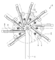
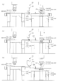
- FIG. 1 is a plan view schematically showing an embodiment of a molten resin compression molding apparatus according to the present invention
- FIG. 2 is an enlarged view of a main part thereof.
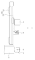
- FIG. 3 is a side view of the main part when the main part shown in FIG. 2 is viewed from the direction of the arrow X in FIG.
- the molding apparatus 10 shown in these drawings includes an extruder 20 that melts, kneads and extrudes a thermoplastic resin from an extrusion port 22, a plurality of conveying means 30 that are arranged around the extrusion port 22 of the extruder 20, A plurality of compression molding dies 40 installed in pairs with the conveying means 30 are provided.
- 2 and 3 show the main part of the molding apparatus 10 by focusing on one of the plurality of conveying means 30 arranged around the extrusion port 22 of the extruder 20.
- molding apparatus 10 shown in figure corresponds to embodiment of the molten resin supply apparatus which concerns on this invention, These melt resin supply methods and molten resin compression molding methods which concern on this invention are these. This apparatus can be suitably used.
- the extruder 20 should just be provided so that the extrusion port 22 opened to the die head 21 may extrude the resin in a molten state substantially downward along the vertical direction.
- the extruder 20 itself can be arbitrarily selected from known extruders such as a single-screw extruder, a multi-screw extruder, and a gear pump assist extruder.
- any resin can be used as long as compression molding is possible.
- polyester resins such as polyethylene terephthalate, polybutylene terephthalate, and polyethylene naphthalate
- polyolefin resins such as polypropylene and polyethylene
- polycarbonate such as polycarbonate, polyarylate, polylactic acid, and copolymers thereof are used.
- each of the conveying means 30 arranged around the extrusion port 22 through which the molten resin is extruded is attached to each of a plurality of drive mechanisms 300 arranged radially around the extrusion port 22.
- the reciprocating movement is alternately performed between the position below the extrusion port 22 and the supply position set for each of the conveying means 30.
- a compression molding die 40 that is paired with each of the conveying means 30 is installed at a supply position set for each conveying means 30.
- the conveying means 30 is pushed out from the extrusion port 22 when passing through the position below the extrusion port 22 toward the compression molding die 40 installed at the supply position. It has the cutting part 31 cut
- the cut portion 31 is formed along a peripheral edge located above the base portion 32, and the inner peripheral surface of the base portion 32 becomes the holding surface 33 on the side surface of the molten resin D cut by the cut portion 31. (See FIG. 5B).
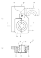
- FIG. 4 is an explanatory view showing an outline of the conveying means 30, FIG. 4 (a) is a plan view thereof, and FIG. 4 (b) is a cross-sectional view taken along line AA of FIG. 4 (a).
- FIG. 5 is an explanatory view showing a state before and after the conveying means 30 passes through a position below the extrusion port 22 of the extruder 20.
- a holding member 34 is attached to the base portion 32 of the conveying means 30 so as to be openable and closable facing the holding surface 33.
- the holding member 34 can be opened and closed around the rotation shaft 35 by, for example, a rotary actuator (not shown).
- a holding member 34 is in an open position when the conveying means 30 passes a position below the extrusion port 22 so as not to prevent cutting of the molten resin by the cutting portion 31 (FIGS. 5A and 5B). b)), and is closed after the molten resin is cut (see FIG. 5C).
- FIG. 4 the state in which the holding member 34 is closed is indicated by a solid line, and the holding member 34 in the open position is indicated by a two-dot broken line.
- the holding member 34 is not shown. Note that the opening / closing operation of the holding member 34 is not limited to a rotation operation around the rotation shaft 35. Although not specifically shown, the opening / closing operation may be performed by, for example, moving the holding member 34 in parallel.
- the holding member 34 When the holding member 34 is closed, a cylindrical space is formed between the holding surface 33 and the holding member 34. In this space, the cut molten resin D is held. At this time, the cut molten resin D is applied to the holding surface 33 provided on the base 32 by using the inertial force when the transfer means 30 moves. It is preferable to hold and carry the sheet.
- the inner diameter of the cylindrical space formed between the holding surface 33 and the holding member 34 is slightly larger than the outer diameter of the extrusion port 22, that is, the outer diameter of the molten resin extruded from the extrusion port 22. Set to be larger.
- each conveying means 30 arranged around the extrusion port 22 of the extruder 20 cuts the molten resin extruded from the extrusion port 22 of the extruder 20 alternately while cutting the molten resin every predetermined length. It suffices that the resin D is transported to the supply position set for each, and can be sequentially supplied to each of the plurality of compression molds 40 installed in pairs.
- each conveying means 30 is configured equally including the drive mechanism 300 so that the cutting of the molten resin extruded from the extrusion port 22 and the conveyance of the cut molten resin D are performed under the same conditions. preferable.
- the feeding position set for each conveying means 20 so that the moving distances of the respective conveying means 30 are equalized and the timing for cutting the molten resin extruded from the extrusion port 22 can be easily adjusted that is, It is preferable that all of the compression molds 40 installed in pairs with each of the conveying means 30 are on the same circumference with the extrusion port 22 of the extruder 20 as the center.
- the specific configuration of the drive mechanism 300 that is responsible for the movement of the conveying means 30 is arbitrary.
- the drive mechanism 300 is composed of a combination of a horizontal drive actuator 301 that reciprocates the conveying means 30 in the horizontal direction and a vertical drive actuator 302 that raises and lowers these in the vertical direction. Can do.
- the vertical drive actuator 302 Prior to cutting the molten resin extruded from the extrusion port 22, the vertical drive actuator 302 moves the horizontal drive actuator 301 over the extrusion port 22 while avoiding a collision with another conveying means 30 that moves at a time difference.
- the conveying means 30 is moved to the upper side in the direction, the conveying means 30 is lifted and lowered together with the horizontal drive actuator 301. The specific operation will be described later.
- the transport means 30 is moved back and forth between the position below the extrusion port 22 and the compression mold 40 (supply position) by the horizontal drive actuator 301.
- the direction toward the compression mold 40 is the forward path
- the direction away from the compression molding machine 40 is the return path
- the extrusion port 22 side in the moving direction is the upper side
- the compression mold 40 side is the lower side.
- the compression molding die 40 has a male die 41 as a lower die and a female die 42 as an upper die, and a concave receiving portion 411 is formed on the upper surface of the male die 41.
- the size and shape of the receiving portion 411 formed on the upper surface of the male mold 41 can be designed according to the size and shape of the supplied molten resin D in consideration of the shape of the product to be molded. In this way, when the molten resin D is dropped and supplied onto the male mold 41, the molten resin D is received by the receiving portion 411, so that the accuracy of the supply position can be increased.
- the supplied molten resin D has a mold structure that is compression-molded into a thin cup-shaped container.
- the specific mold structure of the compression mold 40 depends on the shape of the molded product. Needless to say, it can be changed as appropriate.
- the compression molding die 40 is installed at the supply position set for each conveying means 30, and a mechanism for moving the compression molding die 40 is required. And not. For this reason, even when a higher load is required at the time of compression molding, and it is required to improve the capability of the pressurizing mechanism for clamping and to ensure the strength associated therewith, a component other than the compression molding die 40 is required. The part has no effect. Therefore, it is also suitable for manufacturing synthetic resin molded products that require higher loads without causing problems such as the overall size of the device increasing or the construction cost of the device increasing. can do.
- the compression mold 40 is installed and fixed at a predetermined supply position. Even after the molten resin D is supplied to the compression mold 40, it is easy to prevent the positional accuracy of the molten resin D from being impaired. In particular, as described above, by fixing the male mold 41 that receives the supplied molten resin D, it is possible to prevent the displacement of the molten resin D more reliably.
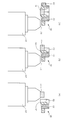
- FIG. 6 and 7 are process diagrams for explaining the operation of the molding apparatus 10. These drawings show an example in which two conveying means 30a, 30b and two compression molds 40a, 40b installed in pairs with each other are arranged around the extrusion port 22 of the extruder 20. ing.
- FIG. 6 shows a process from when the conveying means 30a cuts the molten resin extruded from the extrusion port 22 of the extruder 20 and conveys it to the supply position where the compression molding die 40 is installed.
- These show the steps from when the molten resin D is supplied to the compression mold 40 to when the conveying means 30a starts moving toward the standby position below the other conveying means 30b.
- one conveying means 30a goes over the extrusion port 22 toward the upper side in the moving direction as shown in FIG. 6 (1). In position, it prepares for the cutting of the molten resin extruded from the extrusion port 22 of the extruder 20. At the same time, the other transport unit 30b stands by below the transport unit 30a.
- the conveying means 30a When the molten resin extruded from the extrusion port 22 reaches a predetermined length, the conveying means 30a is moved in the direction of the arrow by the horizontal drive actuator 301. At this time, the conveying means 30a passing through the position below the extrusion port 22 cuts the molten resin extruded from the extrusion port 22, and uses the inertial force generated by the movement of the conveyance means 30a to cut the molten resin. D is held (see FIG. 6 (2)). As described above, when the molten resin is cut, the holding member 34 is closed and the cut molten resin D is held in the space formed between the holding surface 33. 6 and 7, the holding member 34 is not shown.
- the conveyance means 30 stops at the supply position where the compression mold 40 is installed, the molten resin D held by the conveyance means 30a is dropped onto the male mold 41a of the compression mold 40a and the supply is completed (FIG. 6 (3)).
- the other transport unit 30b is prepared for cutting the molten resin that is raised by the vertical drive actuator 302 and pushed out from the extrusion port 22.
- the timing of raising the other conveying means 30b is arbitrary as long as collision with one conveying means 30a is avoided.
- the conveying means 30b may be raised.
- the conveying means 30a is retracted in the direction of the arrow in the figure by the horizontal drive actuator 301 and compressed.
- the female die 42a of the molding die 40 moves downward (see FIG. 7 (5)).
- the molten resin D is compression-molded into a synthetic resin container 50 having a predetermined container shape in a cavity formed by a pair of male and female molds 41a and 42a.
- the conveying means 30a and the conveying means 30b are interchanged, and the conveying means 30b operates in the same manner as the conveying means 30a described above, thereby cutting the molten resin extruded from the extrusion port 22 and compression molding.
- the mold 40b is supplied, and the compression molding of the synthetic resin container is alternately repeated between the compression molding mold 40a and the compression molding mold 40b.
- the compression molding is performed by the molding apparatus 10 in which the two conveying units 30a and 30b and the two compression molding dies 40a and 40b installed in pairs are arranged around the extrusion port 22 of the extruder 20.
- the synthetic resin container 50 manufactured in the present embodiment is preferably a thin cup-shaped container that requires a relatively high load during compression molding, and particularly a thin cup-shaped container having a multilayer structure. Suitable for manufacturing containers.
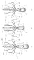
- the internal structure of the die head 21 of the extruder 20 may be as shown in FIG.
- a discharge flow path 220 that is continuous with the extrusion port 22 and a molten resin that is disposed concentrically with the extrusion port 22 flow into the discharge flow channel 220.
- Four annular flow paths 22a, 22b, 22c, and 22d are formed.
- the four annular channels 22a, 22b, 22c, 22d arranged concentrically with the extrusion port 22 are, for convenience, from the outer peripheral side, the first annular channel 22a, the second annular channel 22b, and the third annular channel. 22c and the fourth annular flow path 22d.
- the first annular channel 22a and the second annular channel 22b intersect with the discharge channel 220 separately, and the molten resin sent to the second annular channel 22b is transferred to the first annular channel 22a. It flows into the discharge flow path 220 on the upstream side of the sent molten resin.
- the third annular passage 22c intersects the fourth annular passage 22d on the way to the discharge passage 220, and the molten resin sent to the third annular passage 22c is transferred to the fourth annular passage 22c. Along with the molten resin that has been fed to the discharge channel 220, it flows into the discharge channel 220.
- the inflow position at this time is upstream of the position where the molten resin sent to the second annular flow path 22 b flows into the discharge flow path 220.
- the molten resin sent to the third annular channel 22c and the molten resin sent to the fourth annular channel 22 are opened and closed by opening and closing the valve body 23 as shown in the figure. It is supposed to flow intermittently.
- FIG. 8A shows a state immediately before the molten resin extruded from the extrusion port 22 is cut, and the cut portion is indicated by a chain line in the figure.
- the valve body 23 is open, and the molten resin sent to the third annular channel 22c and the molten resin sent to the fourth annular channel 22 are discharged from the discharge channel.
- the molten resin sent to the second annular flow path 22b and the molten resin sent to the first annular flow path 22a are sequentially joined. To do.
- the valve body 23 is closed, and the molten resin sent to the third annular channel 22 c and the discharge channel of the molten resin sent to the fourth annular channel 22 Block the flow into 220.
- these resins that have previously flowed into the discharge flow path 220 are separated, and the shell body S is formed.
- the shell body S flows down in the discharge flow path 220 while being flattened by the molten resin flowing into the discharge flow path 220 from the second annular flow path 22b (FIG. 8C). reference).
- the interval at which the shell body S is formed, and the shell body included in the cut molten resin D The shape of S can be controlled by appropriately adjusting the timing at which the valve body 23 is opened and closed, the flow rate of the molten resin sent to each annular flow path 22a, 22b, 22c, and 22d.
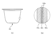
- a cup-shaped container 50 having a thin multilayer structure as shown in FIG. 9 can be formed. That is, the molten resin D supplied to the compression mold 40 is expanded in a cavity formed by a pair of male and female molds 41 and 42. At this time, the intermediate layer 50b and the inner layer 50c are formed by the shell body S. It is formed into a cup-shaped container 50 having a thin multilayer structure.
- FIG. 9 shows an example of a cup-shaped container 50 having a thin multilayer structure formed in the present embodiment
- FIG. 9B shows a cross section of a portion surrounded by a chain line in FIG. .
- the molten resin D cannot be supplied to the compression mold 40 with sufficient accuracy, and the positional accuracy of the molten resin D may be impaired after the supply, the intermediate layer 50b and the inner layer
- the shell S that forms 50c does not spread over the entire container in the process of compression molding or protrudes to the surface of the container, thereby hindering the formation of the intermediate layer 50b and the inner layer 50c.
- the compression mold 40 not only can the molten resin D that has been cut be supplied to the compression mold 40 with sufficient accuracy, but the compression mold 40 is installed at a predetermined supply position. Therefore, even after the molten resin D is supplied to the compression mold 40, it is easy to prevent the positional accuracy of the molten resin D from being impaired.
- the distribution of the formed intermediate layer 50b and inner layer 50c in the container can be made uniform. For this reason, the method of manufacturing a synthetic resin container in the present embodiment is particularly suitable for manufacturing a thin cup-shaped container having a multilayer structure.
- the present invention can be suitably used for the production of a synthetic resin molded product by compression molding, in particular, a thin synthetic resin container having a multilayer structure.
Abstract
Description
このため、圧縮成形に際してより高荷重の負荷が必要とされ、加圧機構の能力向上や、これに伴う強度確保などのために、成形型手段の重量増加が避けられない場合には、回転基盤を回転させるための機構も相応の強度を確保して、成形型手段の重量増加に耐えられるように対処しなければならない。ところが、このようにして対処しようとすると、装置全体が大型化してしまったり、装置の建造コストが増大したりするというような不具合が考えられる。
このため、キャビティ内の所要位置に十分精密に合成樹脂を供給することができても、合成樹脂を供給してから型締めがなされるまでの間に、キャビティ内に供給された合成樹脂が、遠心力によって傾いてしまったりするなどして、キャビティ内での位置にずれが生じてしまうことが懸念される。特に、多層構成とされた薄肉の合成樹脂製容器を圧縮成形によって製造する場合(詳細については後述する)には、圧縮成形時における供給された合成樹脂のキャビティ内での位置や姿勢に格段の精度が要求されるため、キャビティ内に供給された合成樹脂には、遠心力などの外力が作用しないようにすることが望まれる。
20 押出機
22 押出口
30 搬送手段
31 切断部
33 保持面
34 保持部材
300 駆動機構
301 水平駆動用アクチュエーター
302 鉛直駆動用アクチュエーター
40 圧縮成形型
41 雄型(下型)
411 受け部
42 雌型(上型)
50 合成樹脂製容器
まず、本発明に係る溶融樹脂圧縮成形装置の実施形態について説明する。
図1は、本発明に係る溶融樹脂圧縮成形装置の実施形態について、その概略を示す平面図であり、図2は、その要部拡大図である。また、図3は、図2に示す要部を図2中矢印X方向からみた要部側面図である。
なお、図2及び図3は、押出機20の押出口22を中心に配置された複数の搬送手段30のうち、その一つに着目して成形装置10の要部を示すものである。また、図示する成形装置10から圧縮成形型40を除いたものが、本発明に係る溶融樹脂供給装置の実施形態に相当し、本発明に係る溶融樹脂供給方法及び溶融樹脂圧縮成形方法は、これらの装置を好適に利用して実施することができる。
ここで、図4では、保持部材34が閉じた状態を実線で示し、開放位置にある保持部材34を二点破線で示してある。また、図5(a),(b)では、保持部材34の図示を省略している。
なお、保持部材34の開閉動作は、回転軸35を中心とする回動によるものには限定されない。特に図示しないが、例えば、保持部材34を平行移動などさせることによって、その開閉動作がなされるようにしてもよい。
このようにすることで、切断された溶融樹脂Dに対して過度の負荷がかからないようにして、その変形などを有効に回避することができるともに、搬送手段30が供給位置で停止したときに溶融樹脂Dが自重で落下し、これによって成形型40への溶融樹脂Dの供給がなされるようにすることができる。
なお、搬送手段30は、水平駆動用アクチュエーター301によって押出口22の下方位置と、圧縮成形型40(供給位置)との間を往復移動するところ、便宜上、圧縮成形型40に向かう方向を往路、圧縮成形機40から離れる方向を復路とし、その移動方向の押出口22側を上手側、圧縮成形型40側を下手側とする。
このようにすることで、雄型41上に溶融樹脂Dを落下、供給するに際して、溶融樹脂Dを受け部411で受けることにより、その供給位置の精度を高めることができる。さらに、雄型41を固定して、雄型41に対して雌型42が上下動することで型開きと型締めがなされるようにすることで、雌型42が下動して型締めがなされるまでの間に、雄型41上に供給された溶融樹脂Dの位置ずれが生じてしまうのをより確実に防止することができる。
次に、本発明に係る合成樹脂製容器の製造方法の実施形態について説明する。
本発明に係る合成樹脂製容器の製造方法は、上記したような成形装置10を好適に利用して実施することができ、成形装置10の動作を以下に説明することによって、本発明に係る合成樹脂製容器の製造方法の実施形態を説明する。
なお、溶融樹脂の切断がなされると保持部材34が閉じて、保持面33との間に形成される空間内に、切断された溶融樹脂Dが保持されるのは前述した通りであるが、図6及び図7では、保持部材34の図示は省略してある。
このとき、他方の搬送手段30bを上昇させるタイミングは、一方の搬送手段30aとの衝突が避けられる限り任意である。搬送手段30aが押出口22の下方位置を通過した直後に、搬送手段30bが上昇するようにしてもよい。
このようにすることで、本実施形態によれば、合成樹脂製容器50を安定に連続して量産することができる。
一方、第三環状流路22cは、吐出流路220に至る途中で第四環状流路22dに交わっており、第三環状流路22cに送られてきた溶融樹脂が、第四環状流路22に送られてきた溶融樹脂とともに、吐出流路220に流入するようになっている。このときの流入位置は、第二環状流路22bに送られてきた溶融樹脂が吐出流路220に流入する位置よりも上流側にある。そして、第三環状流路22cに送られてきた溶融樹脂と、第四環状流路22に送られてきた溶融樹脂とは、図示するような弁体23を開閉することによって、吐出流路220に間欠的に流入するようになっている。
なお、上記のようにして、押出口22から押し出されてくる溶融樹脂内にシェル体Sを形成するにあたり、シェル体Sが形成される間隔や、切断された溶融樹脂D中に含まれるシェル体Sの形状は、弁体23を開閉するタイミングや、各環状流路22a,22b,22c,22dに送られてくる溶融樹脂の流速などを適宜調整することによって制御することができる。
Claims (12)
- 押出機の押出口から溶融状態にある樹脂をほぼ鉛直下方に押し出すとともに、
前記押出口を中心に配置された複数の搬送手段によって、前記押出口から押し出されてくる溶融樹脂を所定長さごとに交互に切断しつつ、前記搬送手段のそれぞれに設定された供給位置まで搬送することを特徴とする溶融樹脂の供給方法。 - 溶融状態にある樹脂をほぼ鉛直下方に押し出すように押出口を設けた押出機と、
前記押出口から押し出されてくる溶融樹脂を切断する切断部を有し、前記切断部によって切断された溶融樹脂をそれぞれに設定された供給位置まで搬送する複数の搬送手段と
を備え、
前記各搬送手段が、前記押出口を中心に配置されて、前記押出口の下方位置と前記供給位置との間を交互に往復移動することを特徴とする溶融樹脂供給装置。 - 前記搬送手段ごとに設定された前記供給位置の全てが、前記押出口を中心とする同一円周上にある請求項2に記載の溶融樹脂供給装置。
- 前記搬送手段が、前記切断された溶融樹脂の側面に当接し、前記搬送手段の移動時の慣性力を利用して前記切断された溶融樹脂を保持する保持面と、前記保持面に対向して開閉可能に取り付けられた保持部材とを有し、
前記保持面の上方に前記切断部が形成された請求項2又は3のいずれか1項に記載の溶融樹脂供給装置。 - 前記各搬送手段が、前記押出口を中心に放射状に設置された複数の駆動機構のそれぞれに取り付けられて、前記押出口の下方位置と前記供給位置との間を交互に往復移動する請求項2~4のいずれか1項に記載の溶融樹脂供給装置。
- 前記駆動機構が、前記搬送手段を水平方向に往復移動させる水平駆動用アクチュエーターと、前記各搬送手段を鉛直方向に昇降させる鉛直駆動用アクチュエーターとを有する請求項5に記載の溶融樹脂供給装置。
- 押出機の押出口から溶融状態にある樹脂をほぼ鉛直下方に押し出すとともに、
前記押出口を中心に配置された複数の搬送手段によって、前記押出口から押し出されてくる融樹樹脂を所定長さごとに交互に切断しつつ、前記搬送手段と対になって設置された複数の圧縮成形機のそれぞれに供給し、
前記圧縮成形機によって、前記切断された溶融樹脂を所定形状に圧縮成形することを特徴とする溶融樹脂の圧縮成形方法。 - 溶融状態にある樹脂をほぼ鉛直下方に押し出すように押出口を設けた押出機と、
前記押出口から押し出されてくる溶融樹脂を切断する切断部を有し、前記切断部によって切断された溶融樹脂をそれぞれに設定された供給位置まで搬送する複数の搬送手段と、
前記搬送手段と対になって前記搬送手段ごとに設定された前記供給位置に設置されて、前記切断された溶融樹脂を所定形状に圧縮成形する複数の圧縮成形型と
を備え、
前記各搬送手段が、前記押出口を中心に配置されて、前記押出口の下方位置と前記供給位置との間を交互に往復移動することによって、前記切断された溶融樹脂を前記圧縮成形型に順次供給することを特徴とする溶融樹脂圧縮成形装置。 - 前記圧縮成形型の全てが、前記押出口を中心とする同一円周上に設置された請求項8に記載の溶融樹脂圧縮成形装置。
- 押出機の押出口から溶融状態にある樹脂をほぼ鉛直下方に押し出すとともに、
前記押出口を中心に配置された複数の搬送手段によって、前記押出口から押し出されてくる融樹樹脂を所定長さごとに交互に切断しつつ、前記搬送手段と対になって設置された複数の圧縮成形機のそれぞれに供給し、
前記圧縮成形機によって、前記切断された溶融樹脂を所定の容器形状に圧縮成形することを特徴とする合成樹脂製容器の製造方法。 - 前記圧縮成形型が、下型としての雄型及び上型としての雌型を有し、
前記搬送手段によって、前記切断された溶融樹脂を前記圧縮成形型に供給する際に、前記雄型の上面に設けた凹状の受け部で前記切断された溶融樹脂を受ける請求項10に記載の合成樹脂製容器の製造方法。 - 多層構造とされた薄肉カップ状の容器を製造する請求項10又は11のいずれか1項に記載の合成樹脂製容器の製造方法。
Priority Applications (4)
| Application Number | Priority Date | Filing Date | Title |
|---|---|---|---|
| EP09721350.8A EP2263848B8 (en) | 2008-03-19 | 2009-03-17 | Molten resin supply apparatus and method |
| US12/736,088 US8168100B2 (en) | 2008-03-19 | 2009-03-17 | Molten resin supply method, molten resin supply device, molten resin compression molding method, molten resin compression molding device, and synthetic resin container manufacturing method |
| CN2009801091448A CN101970202B (zh) | 2008-03-19 | 2009-03-17 | 熔融树脂供给方法、熔融树脂供给装置、熔融树脂压缩成形方法、熔融树脂压缩成形装置及合成树脂制容器的制造方法 |
| ES09721350.8T ES2636845T3 (es) | 2008-03-19 | 2009-03-17 | Aparato y procedimiento de suministro de resina fundida |
Applications Claiming Priority (2)
| Application Number | Priority Date | Filing Date | Title |
|---|---|---|---|
| JP2008071368A JP4670883B2 (ja) | 2008-03-19 | 2008-03-19 | 溶融樹脂供給装置、溶融樹脂圧縮成形方法、溶融樹脂圧縮成形装置、及び合成樹脂製容器の製造方法 |
| JP2008-071368 | 2008-03-19 |
Publications (1)
| Publication Number | Publication Date |
|---|---|
| WO2009116505A1 true WO2009116505A1 (ja) | 2009-09-24 |
Family
ID=41090906
Family Applications (1)
| Application Number | Title | Priority Date | Filing Date |
|---|---|---|---|
| PCT/JP2009/055089 WO2009116505A1 (ja) | 2008-03-19 | 2009-03-17 | 溶融樹脂供給方法、溶融樹脂供給装置、溶融樹脂圧縮成形方法、溶融樹脂圧縮成形装置、及び合成樹脂製容器の製造方法 |
Country Status (6)
| Country | Link |
|---|---|
| US (1) | US8168100B2 (ja) |
| EP (1) | EP2263848B8 (ja) |
| JP (1) | JP4670883B2 (ja) |
| CN (1) | CN101970202B (ja) |
| ES (1) | ES2636845T3 (ja) |
| WO (1) | WO2009116505A1 (ja) |
Families Citing this family (4)
| Publication number | Priority date | Publication date | Assignee | Title |
|---|---|---|---|---|
| JP2011075009A (ja) | 2009-09-30 | 2011-04-14 | Daiwa Kasei Kogyo Kk | クリップ |
| JP5967076B2 (ja) * | 2011-03-10 | 2016-08-10 | 東洋製罐株式会社 | 溶融樹脂供給システムと溶融樹脂供給方法 |
| JP6215785B2 (ja) | 2014-06-30 | 2017-10-18 | ファナック株式会社 | ワーク搬送システム |
| IT201800009342A1 (it) * | 2018-10-11 | 2020-04-11 | Sacmi Cooperativa Mecc Imola Societa' Cooperativa | Apparato per stampare a compressione oggetti concavi. |
Citations (4)
| Publication number | Priority date | Publication date | Assignee | Title |
|---|---|---|---|---|
| JP2002103428A (ja) * | 2000-09-29 | 2002-04-09 | Toyo Seikan Kaisha Ltd | 多層プリフォームおよびこれを用いて製造した多層ボトル |
| JP2005343110A (ja) * | 2004-06-07 | 2005-12-15 | Toyo Seikan Kaisha Ltd | 溶融合成樹脂供給装置 |
| JP2007216531A (ja) | 2006-02-17 | 2007-08-30 | Toyo Seikan Kaisha Ltd | 圧縮成形システム |
| WO2008032841A1 (fr) * | 2006-09-12 | 2008-03-20 | Toyo Seikan Kaisha, Ltd. | Récipient de type coupe de polypropylène et procédé de moulage de celui-ci |
Family Cites Families (16)
| Publication number | Priority date | Publication date | Assignee | Title |
|---|---|---|---|---|
| US1593525A (en) * | 1925-10-05 | 1926-07-20 | Kurz Kasch Company | Method of molding phenolic condensation products and the like |
| JPS60245517A (ja) * | 1984-05-22 | 1985-12-05 | Toyo Seikan Kaisha Ltd | 圧縮成形装置 |
| JPS6250107A (ja) * | 1985-06-21 | 1987-03-04 | Toyo Seikan Kaisha Ltd | 樹脂供給装置 |
| US5603964A (en) * | 1994-10-07 | 1997-02-18 | Owens-Illinois Closure Inc. | Apparatus for cutting and delivering plastic gobs |
| EP0888867B1 (en) * | 1996-07-09 | 2003-05-02 | Toyota Jidosha Kabushiki Kaisha | Method of manufacturing a hollow resin container |
| US6349838B1 (en) * | 1998-12-25 | 2002-02-26 | Toyo Seikan Kaisha, Ltd. | Plastic bottle and method of producing the same |
| ITRM20010723A1 (it) * | 2001-12-07 | 2003-06-09 | Sipa Spa | Dispositivo e metodo di stampaggio per compressione di articoli in plastica. |
| ITBO20020226A1 (it) * | 2002-04-23 | 2003-10-23 | Sacmi | Apparecchiatura per lo stampaggio a pressione di articoli in materiale plastico , come capsule per la chiusura di contenitore e simili |
| WO2005007378A1 (ja) | 2003-07-14 | 2005-01-27 | Toyo Seikan Kaisya, Ltd. | 圧縮成形機にドロップを強制挿入する方法及び装置並びに成形金型追従式ドロップ供給方法及び装置 |
| ITMO20030289A1 (it) * | 2003-10-23 | 2005-04-24 | Sacmi | Apparati, metodo e articolo. |
| WO2005102647A2 (en) * | 2004-04-16 | 2005-11-03 | Advanced Plastics Technologies, Ltd | Compression moulding multi-layered container-like articles |
| EP1755848A2 (en) * | 2004-04-23 | 2007-02-28 | Sacmi Cooperativa Meccanici Imola Societa' Cooperativa | Apparatuses and method for transferring plastics material to a compression moulding machine |
| JP2006052307A (ja) | 2004-08-11 | 2006-02-23 | Toyo Seikan Kaisha Ltd | 圧縮成形用ポリエステル樹脂、プリフォームの製造方法及びプリフォーム |
| US7331777B2 (en) * | 2005-04-19 | 2008-02-19 | Owens Illinois Closure Inc. | Compression molding machine |
| US7407376B2 (en) * | 2005-07-21 | 2008-08-05 | Graham Packaging Company, L.P. | Compression molding apparatus |
| KR101418610B1 (ko) * | 2006-02-17 | 2014-07-14 | 도요세이칸 그룹 홀딩스 가부시키가이샤 | 용융 수지 덩어리의 공급 방법 및 장치와, 압축 성형 방법 및 장치 |
-
2008
- 2008-03-19 JP JP2008071368A patent/JP4670883B2/ja active Active
-
2009
- 2009-03-17 WO PCT/JP2009/055089 patent/WO2009116505A1/ja active Application Filing
- 2009-03-17 CN CN2009801091448A patent/CN101970202B/zh active Active
- 2009-03-17 US US12/736,088 patent/US8168100B2/en active Active
- 2009-03-17 EP EP09721350.8A patent/EP2263848B8/en active Active
- 2009-03-17 ES ES09721350.8T patent/ES2636845T3/es active Active
Patent Citations (4)
| Publication number | Priority date | Publication date | Assignee | Title |
|---|---|---|---|---|
| JP2002103428A (ja) * | 2000-09-29 | 2002-04-09 | Toyo Seikan Kaisha Ltd | 多層プリフォームおよびこれを用いて製造した多層ボトル |
| JP2005343110A (ja) * | 2004-06-07 | 2005-12-15 | Toyo Seikan Kaisha Ltd | 溶融合成樹脂供給装置 |
| JP2007216531A (ja) | 2006-02-17 | 2007-08-30 | Toyo Seikan Kaisha Ltd | 圧縮成形システム |
| WO2008032841A1 (fr) * | 2006-09-12 | 2008-03-20 | Toyo Seikan Kaisha, Ltd. | Récipient de type coupe de polypropylène et procédé de moulage de celui-ci |
Non-Patent Citations (1)
| Title |
|---|
| See also references of EP2263848A4 |
Also Published As
| Publication number | Publication date |
|---|---|
| US8168100B2 (en) | 2012-05-01 |
| CN101970202A (zh) | 2011-02-09 |
| CN101970202B (zh) | 2013-08-21 |
| EP2263848B8 (en) | 2017-07-19 |
| ES2636845T3 (es) | 2017-10-09 |
| US20110001258A1 (en) | 2011-01-06 |
| JP2009226609A (ja) | 2009-10-08 |
| EP2263848A1 (en) | 2010-12-22 |
| JP4670883B2 (ja) | 2011-04-13 |
| EP2263848B1 (en) | 2017-05-10 |
| EP2263848A4 (en) | 2011-05-11 |
Similar Documents
| Publication | Publication Date | Title |
|---|---|---|
| US5433916A (en) | Utilizing multi cavity mold in extrusion blow molding process | |
| CN101466524B (zh) | 通过挤吹成型及连续的喷嘴缝隙调节制造热塑性塑料空心体的方法 | |
| JP5178827B2 (ja) | 熱可塑性プラスチック材料製中空体の製造方法と装置 | |
| CN87106128A (zh) | 物品的制造 | |
| EP2206592B1 (en) | Compression-molding apparatus | |
| JP4670883B2 (ja) | 溶融樹脂供給装置、溶融樹脂圧縮成形方法、溶融樹脂圧縮成形装置、及び合成樹脂製容器の製造方法 | |
| MXPA06015140A (es) | Procedimiento de produccion y maquina de extrusion y soplado para recipientes de plastico. | |
| MX2007012845A (es) | Aparato para transferir porciones y porcion. | |
| EP2406057B1 (en) | Rotary blow molding machine with moveable mold clamp assemblies and method | |
| EP2830854B1 (en) | Method and apparatus for making hollow bodies | |
| CN101628471B (zh) | 集注胚和吹瓶于一体的塑料制瓶机 | |
| CN1494477A (zh) | 通过在由连续运动工具载送的裙套体上成型出头部体而制成塑料材质的柔性软管的机组 | |
| JPWO2009099129A1 (ja) | 多層樹脂形成ダイヘッドとこれをそなえた押出成形機 | |
| US8419993B2 (en) | Extrusion blow molding machine and method for the production of a hollow plastic body | |
| RU2305033C2 (ru) | Способ и устройство для изготовления полых изделий | |
| CN211334650U (zh) | 一种一体化多层共挤设备 | |
| JP2009226609A5 (ja) | ||
| US20210023761A1 (en) | Vertically added processing for blow molding machine | |
| EP3717199B1 (en) | Blow molding apparatus | |
| CN201552742U (zh) | 集注胚和吹瓶于一体的塑料制瓶机 | |
| JP5023964B2 (ja) | 圧縮成形装置 | |
| JP5303733B2 (ja) | 圧縮成形装置及び圧縮成形方法 | |
| JPH0350690B2 (ja) | ||
| JP2001079932A (ja) | 多層成形品の製造方法及び製造装置 |
Legal Events
| Date | Code | Title | Description |
|---|---|---|---|
| WWE | Wipo information: entry into national phase |
Ref document number: 200980109144.8 Country of ref document: CN |
|
| 121 | Ep: the epo has been informed by wipo that ep was designated in this application |
Ref document number: 09721350 Country of ref document: EP Kind code of ref document: A1 |
|
| WWE | Wipo information: entry into national phase |
Ref document number: 12736088 Country of ref document: US |
|
| REEP | Request for entry into the european phase |
Ref document number: 2009721350 Country of ref document: EP |
|
| WWE | Wipo information: entry into national phase |
Ref document number: 2009721350 Country of ref document: EP |
|
| NENP | Non-entry into the national phase |
Ref country code: DE |