WO2009113415A1 - 通信システム、制御装置及び受信装置 - Google Patents
通信システム、制御装置及び受信装置 Download PDFInfo
- Publication number
- WO2009113415A1 WO2009113415A1 PCT/JP2009/053808 JP2009053808W WO2009113415A1 WO 2009113415 A1 WO2009113415 A1 WO 2009113415A1 JP 2009053808 W JP2009053808 W JP 2009053808W WO 2009113415 A1 WO2009113415 A1 WO 2009113415A1
- Authority
- WO
- WIPO (PCT)
- Prior art keywords
- image
- subframe
- signal
- image signal
- frame
- Prior art date
Links
Images


Classifications
-
- H—ELECTRICITY
- H04—ELECTRIC COMMUNICATION TECHNIQUE
- H04N—PICTORIAL COMMUNICATION, e.g. TELEVISION
- H04N7/00—Television systems
- H04N7/08—Systems for the simultaneous or sequential transmission of more than one television signal, e.g. additional information signals, the signals occupying wholly or partially the same frequency band, e.g. by time division
-
- G—PHYSICS
- G06—COMPUTING; CALCULATING OR COUNTING
- G06T—IMAGE DATA PROCESSING OR GENERATION, IN GENERAL
- G06T1/00—General purpose image data processing
- G06T1/0021—Image watermarking
- G06T1/0085—Time domain based watermarking, e.g. watermarks spread over several images
-
- G—PHYSICS
- G09—EDUCATION; CRYPTOGRAPHY; DISPLAY; ADVERTISING; SEALS
- G09G—ARRANGEMENTS OR CIRCUITS FOR CONTROL OF INDICATING DEVICES USING STATIC MEANS TO PRESENT VARIABLE INFORMATION
- G09G5/00—Control arrangements or circuits for visual indicators common to cathode-ray tube indicators and other visual indicators
-
- H—ELECTRICITY
- H04—ELECTRIC COMMUNICATION TECHNIQUE
- H04N—PICTORIAL COMMUNICATION, e.g. TELEVISION
- H04N21/00—Selective content distribution, e.g. interactive television or video on demand [VOD]
- H04N21/40—Client devices specifically adapted for the reception of or interaction with content, e.g. set-top-box [STB]; Operations thereof
- H04N21/41—Structure of client; Structure of client peripherals
- H04N21/414—Specialised client platforms, e.g. receiver in car or embedded in a mobile appliance
- H04N21/41415—Specialised client platforms, e.g. receiver in car or embedded in a mobile appliance involving a public display, viewable by several users in a public space outside their home, e.g. movie theatre, information kiosk
-
- H—ELECTRICITY
- H04—ELECTRIC COMMUNICATION TECHNIQUE
- H04N—PICTORIAL COMMUNICATION, e.g. TELEVISION
- H04N7/00—Television systems
- H04N7/025—Systems for the transmission of digital non-picture data, e.g. of text during the active part of a television frame
-
- G—PHYSICS
- G06—COMPUTING; CALCULATING OR COUNTING
- G06F—ELECTRIC DIGITAL DATA PROCESSING
- G06F3/00—Input arrangements for transferring data to be processed into a form capable of being handled by the computer; Output arrangements for transferring data from processing unit to output unit, e.g. interface arrangements
- G06F3/14—Digital output to display device ; Cooperation and interconnection of the display device with other functional units
- G06F3/147—Digital output to display device ; Cooperation and interconnection of the display device with other functional units using display panels
-
- G—PHYSICS
- G06—COMPUTING; CALCULATING OR COUNTING
- G06T—IMAGE DATA PROCESSING OR GENERATION, IN GENERAL
- G06T2201/00—General purpose image data processing
- G06T2201/005—Image watermarking
- G06T2201/0051—Embedding of the watermark in the spatial domain
-
- G—PHYSICS
- G09—EDUCATION; CRYPTOGRAPHY; DISPLAY; ADVERTISING; SEALS
- G09G—ARRANGEMENTS OR CIRCUITS FOR CONTROL OF INDICATING DEVICES USING STATIC MEANS TO PRESENT VARIABLE INFORMATION
- G09G2358/00—Arrangements for display data security
-
- G—PHYSICS
- G09—EDUCATION; CRYPTOGRAPHY; DISPLAY; ADVERTISING; SEALS
- G09G—ARRANGEMENTS OR CIRCUITS FOR CONTROL OF INDICATING DEVICES USING STATIC MEANS TO PRESENT VARIABLE INFORMATION
- G09G2380/00—Specific applications
- G09G2380/06—Remotely controlled electronic signs other than labels
-
- G—PHYSICS
- G09—EDUCATION; CRYPTOGRAPHY; DISPLAY; ADVERTISING; SEALS
- G09G—ARRANGEMENTS OR CIRCUITS FOR CONTROL OF INDICATING DEVICES USING STATIC MEANS TO PRESENT VARIABLE INFORMATION
- G09G5/00—Control arrangements or circuits for visual indicators common to cathode-ray tube indicators and other visual indicators
- G09G5/12—Synchronisation between the display unit and other units, e.g. other display units, video-disc players
-
- H—ELECTRICITY
- H04—ELECTRIC COMMUNICATION TECHNIQUE
- H04N—PICTORIAL COMMUNICATION, e.g. TELEVISION
- H04N13/00—Stereoscopic video systems; Multi-view video systems; Details thereof
- H04N13/30—Image reproducers
- H04N13/332—Displays for viewing with the aid of special glasses or head-mounted displays [HMD]
- H04N13/341—Displays for viewing with the aid of special glasses or head-mounted displays [HMD] using temporal multiplexing
-
- H—ELECTRICITY
- H04—ELECTRIC COMMUNICATION TECHNIQUE
- H04N—PICTORIAL COMMUNICATION, e.g. TELEVISION
- H04N13/00—Stereoscopic video systems; Multi-view video systems; Details thereof
- H04N13/30—Image reproducers
- H04N2013/40—Privacy aspects, i.e. devices showing different images to different viewers, the images not being viewpoints of the same scene
- H04N2013/403—Privacy aspects, i.e. devices showing different images to different viewers, the images not being viewpoints of the same scene the images being monoscopic
Definitions
- the present invention relates to a communication system that transmits information by an image or a moving image displayed on a display or the like, and a control device and a reception device used in the communication system.
- a visible light communication technique for transmitting information by an image or a moving image displayed on a display or the like
- a specific two-dimensional code (QR code) or the like is displayed on a part of the display image, and the two-dimensional image is displayed by a camera such as a mobile phone.
- QR code specific two-dimensional code
- Systems are known in which a code is imaged and information is received.
- failure diagnosis data including an abnormality signal indicating the abnormality is generated, and the failure diagnosis data is represented by a symbol code (barcode or two-dimensional).
- a symbol code barcode or two-dimensional
- Japanese Laid-Open Patent Publication No. 2006-020204 discloses a server device specified by information of a read two-dimensional code, which reads a two-dimensional code printed on a display medium with a terminal device and provides contents such as an image and sound. A configuration is described in which various contents are acquired by accessing the.
- a display device that displays a public image and an image (secret image) provided only to a specific user in a time-sharing manner, and transmits light in synchronization with the display timing of the secret image
- a so-called secure display technology combined with an optical shutter.
- a public image provided to an unspecified person by a display device, a secret image provided only to a specific user, and an inverted image of the secret image are displayed in a time-sharing manner within one frame, and the user
- the optical shutter existing in front of is switched to the transmission state in synchronization with the display timing of the secret image.
- the secret image is visually recognized by the user who uses the optical shutter, and the secret image is superimposed on the inverted image to a non-specific person (public) who does not use the optical shutter to create a halftone (gray) image. Therefore, only the public image is visually recognized.
- a URL Uniform Resource Locator
- a server device that displays detailed information about a product displayed as a public image by a public image and provides a detailed image of the product displayed as a secret image with a two-dimensional code, etc.
- the convenience is low.
- a synchronization signal synchronized with the display of the secret image is transmitted from the display device to the optical shutter so that only the secret image displayed on the display device by the optical shutter is transmitted and the public image and the reverse image are blocked. Need to send.
- the present invention provides a communication system capable of performing visible light communication with simple means without impairing the beauty of public images and without using a synchronization signal, etc., and a control device and a reception device used in the communication system. For the purpose.
- the communication system of the present invention divides one frame into a plurality of subframes, and the image signal of the first image is divided into the plurality of signal levels so that the sum of the signal levels in the one frame becomes zero.
- a control device that distributes the sub-frames and superimposes them on the image signal of the second image;
- a display device that displays an image based on the image signal output from the control device for each subframe;
- An image displayed on the display device is taken every cycle that is the same as the cycle of the subframe, and a difference between two image signals obtained every cycle that is the same as the cycle of the subframe is obtained.
- a receiving device for acquiring and displaying an image signal of an image Have
- the control device of the present invention is a control device that outputs an image signal for displaying one frame divided into a plurality of subframes, A level modulation unit for generating image signals for each of the sub-frames of the first image, in order to distribute and display the plurality of sub-frames so that the sum of the signal levels in the one frame is zero; A signal synthesizer that superimposes the image signal of the first image for each subframe on the image signal of the second image; Have
- the receiving apparatus divides one frame into a plurality of sub-frames, captures an image displayed on a display device that displays a first image and a second image, and captures the first image or the second image.
- a receiving device that extracts and displays the image of A camera unit that captures an image displayed on the display device at the same period as the period of the subframe;
- a subframe memory for sequentially storing image signals output from the camera unit at the same period as the period of the subframe;
- a subtractor for obtaining a difference between two image signals stored in the sub-frame memory and outputting an image signal of the first image;
- FIG. 1 is a schematic diagram showing a configuration example of a communication system according to the present invention.
- FIG. 2 is a block diagram illustrating a configuration example of the display device and the control device illustrated in FIG.
- FIG. 3 is a block diagram illustrating a configuration example of the receiving apparatus according to the first embodiment.
- FIG. 4 is a schematic diagram illustrating an operation example of the communication system according to the first embodiment.
- FIG. 5 is a schematic diagram illustrating an operation example of the communication system according to the first embodiment.
- FIG. 6 is a block diagram illustrating another configuration example of the receiving apparatus according to the second embodiment.
- FIG. 7 is a schematic diagram illustrating an operation example of the communication system according to the second embodiment.
- FIG. 8 is a schematic diagram illustrating an operation example of the communication system according to the second embodiment.
- FIG. 1 is a schematic diagram showing a configuration example of a communication system according to the present invention.
- FIG. 2 is a block diagram illustrating a configuration example of the display device and the control device illustrated
- FIG. 9 is a block diagram illustrating a configuration example of the receiving apparatus according to the third embodiment.
- FIG. 10 is a schematic diagram illustrating an operation example of the communication system according to the third embodiment.
- FIG. 11 is a schematic diagram illustrating an operation example of the communication system according to the third embodiment.
- FIG. 12 is a block diagram illustrating another configuration example of the receiving apparatus according to the third embodiment.
- FIG. 13 is a schematic diagram illustrating an operation example of the communication system according to the fourth embodiment.
- FIG. 14 is a schematic diagram illustrating an operation example of the communication system according to the fourth embodiment.
- FIG. 1 is a schematic diagram showing a configuration example of a communication system according to the present invention.
- the communication system of the present invention is a basic image (corresponding to a public image of the secure display technology) that is an image such as an advertisement provided to a user and an image provided only to a specific user.
- a display device 1 that displays an embedded image (corresponding to a secret image of the secure display technology), a control device 3 that outputs an image signal for causing the display device 1 to display an image, and a display device 1 owned by a user.
- a receiving device 2 that extracts and displays a basic image or an embedded image from the displayed image. Note that the “first image” described in the claims corresponds to the embedded image, and the “second image” corresponds to the basic image.
- the control device 3 divides one frame into a plurality of subframes, displays the basic image on the display device 1 in each subframe, and the sum of the signal levels within one frame of the image signal of the embedded image becomes zero.
- the image signal of the embedded image after dispersion is superimposed on the image signal of the basic image and displayed on the display device 1.
- the sum of the signal levels becomes zero when the luminance values of corresponding pixels of each image signal are added, the added value becomes a constant luminance value (for example, intermediate gray) in all the pixels. Point to. Therefore, the user who is viewing the image displayed on the display device 1 cannot view the embedded image because the embedded image of each subframe is visually integrated by time integration.
- Display device 1 displays an image based on the image signal output from control device 3 for each subframe.
- the receiving device 2 captures an image displayed on the display device 1 at the same period as the subframe period, and obtains an image signal of an embedded image by obtaining a difference between the two image signals obtained at each period.
- the image signal of the basic image is acquired and displayed by adding the image signals obtained for each period.
- one frame of an image displayed on the display device 1 is divided into, for example, three subframes.
- the control device 3 displays the basic image on the display device 1 in the first subframe, and displays the image signal of the embedded image superimposed on the image signal of the basic image in the second subframe, for example, in the positive direction.
- the image is displayed on the device 1, and the image signal of the embedded image is superimposed on the image signal of the basic image in the third subframe in the negative direction at the same signal level as the embedded image of the second subframe and displayed on the display device 1. .
- the positive direction embedded image displayed in the second subframe and the negative direction embedded image displayed in the third subframe are canceled by the user who is viewing the display image of the display device 1 ( Only a basic image is perceived by being equivalent to combining a reverse image with a so-called secret image.
- the image signal of the embedded image to be superimposed on the basic image in each sub-frame only needs to be distributed so that the sum of the signal levels within one frame is zero, and the image signal of the embedded image is corrected with respect to the image signal of the basic image.
- the subframe superimposed in the direction or the negative direction may be any of the first subframe to the third subframe.
- the receiving device 2 captures an image displayed on the display device 1 at the same period as the period of the subframe with a camera included in the own apparatus.
- an image signal corresponding to the first subframe (first subframe) photographed by the camera, an image signal corresponding to the second subframe (second subframe), and the third subframe (third The image signal of the basic image can be obtained by adding the image signals corresponding to (subframes). Further, if the difference between the image signals corresponding to the first subframe and the second subframe, or the difference between the image signals corresponding to the first subframe and the third subframe is obtained, an image signal of the embedded image can be obtained. It is done.
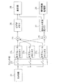
- FIG. 2 is a block diagram showing a configuration example of the display device and the control device shown in FIG. 1
- FIG. 3 is a block diagram showing a configuration of the receiving device of the first embodiment.
- the control device 3 includes a level modulation unit 11, a signal synthesis unit 12, and a subframe memory unit 13, and the display device 1 includes a subframe memory unit 13 and a display unit 14.
- the image signal of the basic image (basic image signal in FIG. 2) and the image signal of the embedded image (embedded image signal in FIG. 2) are input to the control device 3 from an electronic device (not shown) provided outside. Alternatively, it may be generated inside the control device 3.
- the level modulation unit 11 generates an image signal of an embedded image for each subframe to be superimposed on the image signal of the basic image in each subframe.
- a positive image signal of an embedded image to be superimposed in the second subframe and a negative image signal to be superimposed in a third subframe are generated.
- the signal synthesizer 12 superimposes the image signal of the embedded image on the image signal of the basic image and outputs it to the subframe memory unit 13 for each subframe.
- the subframe memory unit 13 stores the image signal for each subframe output from the signal synthesis unit 12 as image data.
- the subframe memory unit 13 may be provided in the control device 3 instead of the display device 1.
- the display unit 14 displays the image for each subframe in accordance with the image signal stored in the subframe memory unit 13.
- the control device 3 can be realized by an A / D converter for processing an image signal, a CPU, a DSP or a logical operation circuit that executes processing according to a program.
- a liquid crystal display, an LED display, a DLP type projector device, an organic EL display, a PDP, or the like can be used as the display device 1.
- the receiving device 2 includes a camera unit 21, a switch unit 22, subframe memories (# 1 to # 3) 23 1 to 23 3 , an adder 24, a subtracter 25, a video memory 26, an embedded image.
- the camera unit 21 captures the image displayed on the display unit 14 of the display device 1 at the same cycle as the display cycle of the subframe.
- the camera unit 21 has a configuration in which the shooting cycle is set in advance to be the same as the display cycle of the subframe of the display device 1 or the shooting cycle is the same as the display cycle of the subframe of the display device 1 by a user operation. It is set as the structure which can be set or selected so that it may become.
- the switch unit 22 sequentially distributes the image signal output from the camera unit 21 to the three subframe memories 23 1 to 23 3 at the same period as the subframe.
- the subframe memories 23 1 to 23 3 store the image signal output from the switch unit 22 as image data.
- the adder 24 adds the image signals stored in the subframe memories 23 1 to 23 3 and outputs the result to the video memory 26.
- Subtractor 25 the sub-frame memory (# 1) 23 from the stored image signals to one subtracts the image signal stored in, for example, the sub-frame memory (# 3) 23 3, and output to the image memory 27 embedded .
- the video memory 26 stores the image data of the basic image output from the adder 24.
- the embedded image memory 27 stores the image data of the embedded image output from the subtracter 25.
- the display unit 28 displays a basic image or an embedded image using image data stored in the video memory 26 or the embedded image memory 27 in accordance with a user operation.
- the signal decoding processing unit 29 performs necessary signal processing on the image data of the embedded image output from the subtracter 25. For example, when the embedded image is a two-dimensional code, the signal decoding processing unit 29 decodes the two-dimensional code.
- the receiving device 2 includes a mobile phone, a PDA (Personal Digital Assistant), or a portable personal computer equipped with a camera unit 21 that captures images at the same period as the display period of the subframe of the display device 1.
- a terminal device is used.
- 4 and 5 are schematic diagrams showing an operation example of the communication system according to the first embodiment. 4 and 5 show examples in which a triangular basic image 31 and a circular embedded image 32 are displayed.
- the control device 3 divides one frame into three subframes, causes the display device 1 to display the basic image in the first subframe, and the image signal of the basic image in the second subframe.
- the image signal of the embedded image is superimposed on the image signal of the embedded image in the positive direction and displayed on the display device 1
- the image signal of the embedded image is superimposed on the image signal of the basic image in the negative direction and displayed on the display device 1 in the third subframe.
- the receiving device 2 of the first embodiment takes an image displayed on the display device 1 with the camera unit 21 at the same cycle as the display cycle of the subframe of the display device 1 by the user's operation.
- an image sensor such as a CCD (Charge Coupled Devices) or CMOS is used for the camera unit 21 included in the mobile terminal device used as the receiving device 2.
- CCD Charge Coupled Devices
- CMOS complementary metal-oxide-semiconductor
- charges generated in the CCD and CMOS according to the amount of received light are only generated for a certain period (for example, a period of one subframe). Operates in accumulation mode to integrate.
- the receiving device 2 of the present embodiment is not configured to receive a synchronization signal synchronized with a frame or subframe from the display device 1, the integration period (a period corresponding to one subframe) of the camera unit 21 and the display device 1 are used.
- the displayed subframe is not always synchronized.
- the integration period of the camera unit 21 and the display period of the subframes of the display device 1 are the same, and the display device 1 repeatedly displays frames composed of the same subframe. Therefore, even if the integration period of the camera unit 21 and the subframe displayed on the display device 1 are not synchronized, each image signal obtained for each imaging cycle includes information on the basic image and the embedded image. Yes.
- FIG. 4A shows a display image of the display device 1 and an image signal (photographing) output from the camera unit 21 when the integration period of the camera unit 21 and the subframe displayed on the display device 1 are synchronized. An example of signal) is shown.
- FIG. 4B shows an embedded image output from the subtracter 25 of the receiving device 2 and its image signal when the integration period of the camera unit 21 and the subframe displayed on the display device 1 are synchronized. An example is shown.
- FIG. 4B an image (embedded image) of a difference between image signals corresponding to the image a (integrated value in the period a) and the image c (integrated value in the period c) shown in FIG.
- the image (embedded image) of the difference between the image signals corresponding to the image e (integrated value of the period e) and the absolute value thereof are shown.
- 4A shows a signal level corresponding to the AA ′ line of the display image shown in FIG. 4A
- the image signal shown in FIG. 4B is shown in FIG. 4A.
- the signal level corresponding to the AA ′ line of the displayed image is shown.
- FIG. 5A shows the display image of the display device 1 and the output from the camera unit 21 when the integration period of the camera unit 21 is delayed by 1 ⁇ 2 period with respect to the subframe displayed on the display device 1.
- An example of an image signal (photographing signal) to be performed is shown.
- FIG. 5B shows an embedding output from the subtracter 25 of the receiving device 2 when the integration period of the camera unit 21 is delayed by a half period with respect to the subframe displayed on the display device 1.
- An example of an image and its image signal is shown.
- FIG. 5B an image (embedded image) of a difference between image signals corresponding to the image g (integrated value of the period g) and the image i (integrated value of the period i) shown in FIG.
- 5A shows the signal level corresponding to the AA ′ line of the display image shown in FIG. 5A
- the image signal shown in FIG. 5B is shown in FIG.
- the signal level corresponding to the AA ′ line of the displayed image is shown.
- the first sub If the difference between the image signals corresponding to the frame and the third subframe is obtained, the image signals of the basic images included in the first subframe and the third subframe are canceled out, and the remaining embedded image signal is obtained. can get. Also, if the image signals corresponding to the first to third subframes are added, the image signals of the embedded images included in the second and third subframes are offset, and the remaining basic signals An image signal of the image is obtained.
- visible light communication can be performed with simple means without impairing the beauty of public images and without using a synchronization signal or the like.
- one frame is divided into, for example, three subframes, and the image signal of the embedded image is distributed and superimposed on all the divided subframes. That is, in the control device 3 of the second embodiment, the image signal of the embedded image to be superimposed on the basic image in the first subframe is X, and the image signal of the embedded image to be superimposed on the basic image in the second subframe. Y, where Z is the image signal of the embedded image to be superimposed on the basic image in the third subframe, the signal level of the embedded image in each subframe is set so that the following equation (1) is satisfied.
- the embedded image signal level superimposed on each subframe in the same frame is different from each other, and the total signal level of the embedded image superimposed on each subframe in the same frame is zero. Even if the image signal is distributed to each subframe, the embedded image displayed in each subframe is canceled and only the basic image is perceived by the user looking at the display device 1 as in the first embodiment. Is done.
- the receiving device 2 of the second embodiment captures an image displayed on the display device 1 at the same period as the period of the subframe by the camera unit 21. .
- the image signals corresponding to the first to third subframes captured by the camera unit 21 are added, the embedded image included in each subframe is added. The image signals are canceled out, and the image signal of the remaining basic image is obtained. Further, if the difference between two image signals among the image signals corresponding to the first to third subframes is obtained, the image signals of the basic images included in those subframes are canceled out and remain. An image signal of the embedded image is obtained.
- the control device 3 of the present embodiment generates an image signal of an embedded image with signal levels of X, Y, and Z to be superimposed on the basic image in each subframe by the level modulation unit 11 shown in FIG.
- the signal synthesis unit 12 superimposes the image signal of the embedded image with the signal levels X, Y, and Z on the image signal of the basic image for each subframe, and outputs it to the subframe memory unit 13. Since other configurations and operations are the same as those of the control device 3 of the first embodiment, the description thereof is omitted. Since the configuration and operation of the display device 1 are the same as those of the display device 1 of the first embodiment, description thereof is omitted.
- the receiving apparatus 2 can be realized by changing the connection between the subtracter 25 and the subframe memories 23 1 to 23 3 shown in FIG. That is, the sub-frame memory (# 1) 23 1 and the sub-frame memory (# 2) the image signal stored in the 23 2 to output to the subtracter 25, by the subtractor 25, e.g., sub-frame memory (# 1) 23 subframe memory from the image signal stored in the 1 (# 2) subtracting the image signal stored in 23 2, may be output to the image memory 27 embedded.
- the receiving device 2 includes an adder without storing the image signal corresponding to the third subframe output from the switch unit 22 in the subframe memory 23 as shown in FIG. This can also be realized by a configuration that directly outputs to 24.
- FIG. 7A shows an example of an image signal (display signal) of the display device 1 when the integration period of the camera unit 21 and the subframe displayed on the display device 1 are synchronized.
- FIG. 7B shows an example of an image signal output from the subtracter 25 of the receiving device 2 when the integration period of the camera unit 21 and the subframe displayed on the display device 1 are synchronized.
- FIG. 8A shows an image signal (display signal) and reception of the display device 1 when the integration period of the camera unit 21 is delayed by a half cycle with respect to the subframe displayed on the display device 1.
- An example of an image signal (photographing signal) output from the camera unit 21 of the apparatus 2 is shown.
- FIG. 8B shows an image output from the subtracter 25 of the receiving device 2 when the integration period of the camera unit 21 is delayed by a half cycle with respect to the subframe displayed on the display device 1.
- An example of a signal is shown.
- FIG. 8B the absolute value of the difference between the image signal g (integrated value of the period g) and the image signal h (integrated value of the period h) shown in FIG.
- the integration period of the camera unit 21 and the subframe displayed on the display apparatus 1 are synchronized. Regardless of whether or not, if the difference between the image signals corresponding to the first subframe and the third subframe is obtained, the image signal of the embedded image can be obtained.
- a basic image can be obtained by adding image signals corresponding to the first to third subframes.
- visible light communication can be performed with simple means without impairing the beauty of public images and without using a synchronization signal or the like.
- the number of subframe memories 23 can be reduced, so that the receiving apparatus 2 can be compared with the first embodiment. The cost can be reduced.
- the third embodiment divides one frame into three subframes, and outputs an image signal in which the image signal of the embedded image is dispersed and superimposed on all the divided subframes. It is the structure to do. Since the configuration and operation of the control device 3 of the third embodiment are the same as those of the control device 3 of the second embodiment, the description thereof is omitted. Moreover, since the structure and operation
- the receiving device 2 takes an image displayed on the display device 1 at the same cycle as the subframe by the camera unit 21 included in the own device.
- the first subframe and the second subframe are continuously integrated, and the image signals of these two subframes are added.
- the embedded image is obtained by obtaining a difference in signal level between the image signal (integrated signal) obtained by adding the image signals of the first subframe and the second subframe and the image signal of the third subframe.
- the basic image is acquired by adding the integration signal of the first subframe and the second subframe and the image signal of the third subframe.
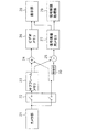
- FIG. 9 is a block diagram illustrating a configuration example of the receiving apparatus according to the third embodiment.
- the reception device 2 includes a camera unit 21, a switch unit 22, a subframe memory (# 1) 23 1 , a subframe memory (# 2) 23 2 , and an amplification unit 30. , An adder 24, a subtracter 25, a video memory 26, an embedded image memory 27, a display unit 28, and a signal decoding processing unit 29.
- the camera unit 21 of the third embodiment continuously integrates the first subframe and the second subframe, and adds an image signal (integration) of the image signals of the first subframe and the second subframe. Signal) and the image signal of the third subframe are acquired.
- Switch 22 distributes the integrated signal of the first sub-frame and second sub-frames output from the camera unit 21 in the sub-frame memory (# 1) 23 1, sub-frame image signal of the third sub-frame memory (# 2) distributed to 23 2.
- Subframe memory (# 1) 23 1 and the sub-frame memory (# 2) 23 2 stores the image signal output from the switching section 22 as image data.
- the adder 24 outputs to the sub-frame memory (# 1) 23 image signals stored in the 1 and the sub-frame memory (# 2) video memory 26 adds the image signal stored in the 23 2.
- Amplifying section 30 outputs to the sub-frame memory (# 2) the signal level of the image signal stored in the 23 2 to twice the subtracter 25.
- Subtractor 25 the sub-frame memory (# 1) 23 1 output signal of the amplifier 30 from the stored image signal is subtracted, and outputs to the image memory 27 embedded.
- Other configurations and operations are the same as those of the receiving apparatus 2 according to the first embodiment, and a description thereof will be omitted.
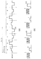
- FIG. 10A shows an example of an image signal (display signal) of the display device 1 when the integration period of the camera unit 21 and the subframe displayed on the display device 1 are synchronized.
- FIG. 10B shows an example of an image signal output from the subtracter 25 of the receiving device 2 when the integration period of the camera unit 21 and the subframe displayed on the display device 1 are synchronized.
- FIG. 11A shows an image signal (display signal) and reception of the display device 1 when the integration period of the camera unit 21 is delayed by 1 ⁇ 2 period with respect to the subframe displayed on the display device 1.
- An example of an image signal (photographing signal) output from the camera unit 21 of the apparatus 2 is shown.
- FIG. 11B shows an image output from the subtracter 25 of the receiving device 2 when the integration period of the camera unit 21 is delayed by a half cycle with respect to the subframe displayed on the display device 1.
- An example of a signal is shown. 11B, the difference between the integral value of the image signals g and h (integral value of the period g + h) and the image signal i (integral value of the period i) shown in FIG.
- the absolute value of the difference between the integral value of the integral value) and the double value of the image signal k (integral value of the period k) is shown.
- the receiving apparatus 2 of the third embodiment also displays the integration period of the camera unit 21 and the display apparatus 1 as in the second embodiment.
- a basic image can be obtained by adding an image signal obtained by integrating the first subframe and the second subframe and an image signal corresponding to the third subframe.
- the image signal corresponding to the third subframe output from the camera unit 21 is directly supplied to the adder 24 and the amplifier 30.
- Such a configuration also operates in the same manner as the configuration shown in FIG. If the configuration of the receiving device 2 shown in FIG. 12 is adopted, the number of subframe memories 23 can be further reduced as compared with the receiving device 2 shown in FIG. 9, so that the first embodiment and the second embodiment Compared to the embodiment, the cost of the receiving device 2 can be further reduced.
- visible light communication can be performed with simple means without impairing the beauty of public images and without using a synchronization signal or the like.
- the number of subframe memories 23 can be reduced similarly to the receiving device 2 of the second embodiment, the cost of the receiving device 2 can be reduced as compared with the first embodiment.
- the difference between the image signal obtained by integrating the first subframe and the second subframe and the image signal obtained by doubling the signal level of the third subframe is obtained to calculate the embedded image. Since the image signal is acquired, the signal level of the embedded image can be increased.
- FIGS. 13 and 14 show examples of operations of the display device 1 and the receiving device 2 when one frame is divided into four subframes.
- the control device 3 displays on the display device 1 an image in which the image signal of the embedded image is dispersed and superimposed on all subframes constituting one frame. Since the configuration and operation of the control device 3 of the fourth embodiment are the same as those of the control device 3 of the second embodiment, the description thereof is omitted. Moreover, since the structure and operation
- the receiving apparatus 2 of the present embodiment can use the configuration shown in FIG. 3, FIG. 6, FIG. 9, or FIG.
- four subframe memories for storing image signals corresponding to each subframe
- Subframe memories # 1 to # 4 are required.
- the image signal of the basic image can be obtained by adding the image signals stored in the four subframe memories 23, and the difference between the image signals stored in any two subframe memories 23 can be obtained.
- an image signal of an embedded image can be obtained. This is the same when the number of subframes in one frame is an arbitrary value of 4 or more.
- image signals corresponding to the third subframe and the fourth subframe are output directly to the adder 24 without being stored in the subframe memory 23, respectively. Good.
- image signals corresponding to the third subframe and the fourth subframe are output directly to the adder 24 without being stored in the subframe memory 23, respectively.
- image signals corresponding to the third subframe and the fourth subframe are output directly to the adder 24 without being stored in the subframe memory 23, respectively.
- the image signal of the basic image can be obtained by adding the image signals stored in the subframe memories 23 1 and 23 2 .
- the integration signals of the first to third subframes are stored in the subframe memory 23, and the image signal of the fourth subframe is added to the adder 24 and What is necessary is just to output directly to the amplifier 30.
- it is possible to obtain the image signal of the basic image by adding the integration signal stored in the subframe memory 23 and the image signal of the fourth subframe, and amplifying the image signal of the fourth subframe. After the image is multiplied by 30, the difference between the image signal stored in the subframe memory 23 and the image signal output from the amplifying unit 30 can be obtained to obtain the image signal of the embedded image.
- the following configuration may be used to set the number of subframes in one frame to an arbitrary value of 4 or more.
- an integrated signal obtained by adding the image signals of the first subframe to the (n ⁇ 1) th subframe is used as a subframe memory (# 1).
- 23 1 and stored in (the sub-frame memory 23 in the configuration shown in FIG. 12), in the configuration shown in which the image signal of the sub-frame of the n subframe memory (# 2) may be stored in the 23 2 (FIG. 12 integrated signal
- the image signal of the n-th subframe may be directly output to the adder 24 and the amplifying unit 30).
- the image signal of the basic image can be obtained by adding the integration signal stored in the subframe memory 23 and the image signal of the nth subframe. Further, after the image signal of the nth subframe is multiplied by n ⁇ 1 by the amplifying unit 30, the difference between the integrated signal stored in the subframe memory 23 and the image signal output from the amplifying unit 30 is obtained. It is possible to obtain an image signal.
- FIG. 13A shows an example of an image signal (display signal) of the display device 1 when the integration period of the camera unit 21 and the subframe displayed on the display device 1 are synchronized.
- FIG. 13B shows an example of an image signal output from the subtracter 25 of the receiving device 2 when the integration period of the camera unit 21 and the subframe displayed on the display device 1 are synchronized.
- FIG. 14A shows an image signal (display signal) and reception of the display device 1 when the integration period of the camera unit 21 is delayed by 1 ⁇ 2 period with respect to the subframe displayed on the display device 1.
- An example of an image signal (photographing signal) output from the camera unit 21 of the apparatus 2 is shown.
- FIG. 14B shows an image output from the subtracter 25 of the receiving device 2 when the integration period of the camera unit 21 is delayed by 1 ⁇ 2 period with respect to the subframe displayed on the display device 1.
- An example of a signal is shown.
- FIG. 14B the absolute value of the difference between the image signal i (integrated value in the period i) and the image signal j (integrated value in the period j) shown in FIG.
- the integration period of the camera unit 21 and the display device 1 are the same as in the first to third embodiments. If the difference between the image signal corresponding to the first subframe and the image signal corresponding to the second subframe is obtained regardless of whether or not the subframes displayed in FIG. can get.
- visible light communication can be performed with simple means without impairing the beauty of public images and without using a synchronization signal or the like. Become. Further, since the number of subframes is larger than in the first to third embodiments, the flicker of the basic image is further reduced for the user who is viewing the display device 1 without using the optical shutter.
- the receiving device 2 divides one frame into three subframes. If the images displayed on the display device 1 are taken at the same period, even if the condition that the signal levels of all the embedded images are different as in the second embodiment, the image of each subframe is not satisfied. An embedded image can be obtained by obtaining a difference between signals. However, even in this case, the sum of the signal levels of the embedded images in the same frame needs to be zero.
- the control device 3 When the display device 1 displays one frame divided into two subframes, the control device 3 superimposes the image signal of the embedded image in the positive direction on the image signal of the basic image in one subframe. Are displayed on the display device 1, and the image signal of the embedded image is superimposed on the image signal of the basic image in the other subframe in the negative direction at the same signal level as the embedded image of one subframe and displayed on the display device 1. .
- the imaging cycle of the receiving device 2 is shifted by a half cycle with respect to the display cycle of the subframe of the display device 1, the image signal of the embedded image included in each image signal output from the camera unit 21. It will be offset. Therefore, when one frame is divided into two subframes for display, it is necessary to shift the imaging cycle of the receiving device 2 or amplify the image signal corresponding to one subframe output from the camera unit 21. .
- the difference between two image signals continuously output from the camera unit 21 or the difference between the integral signal and the image signal output subsequently is calculated.
- an embedded image is obtained by obtaining
- the signal level of the embedded image for each subframe is different, embedding is performed even if the difference between the image signals of any two subframes in one frame is obtained.
- An image can be obtained.
- the signal level of the embedded image is the same as the image signal of two subframes in which the embedded image cancels, for example, the image signal b and the image signal c shown in FIG.
- the image signals of two subframes in which the image is superimposed in the positive direction and the negative direction with respect to the image signal of the basic image cannot be used for the embedded image acquisition process.
Abstract
Description
前記制御装置から出力された画像信号に基づく画像を前記サブフレーム毎に表示する表示装置と、
前記サブフレームの周期と同一の周期毎に前記表示装置に表示された画像を撮影し、前記サブフレームの周期と同一の周期毎に得られる2つの画像信号の差を求めることで前記第1の画像の画像信号を取得して表示する受信装置と、
を有する。
前記1フレーム内の信号レベルの総和がゼロとなるように前記複数のサブフレームに分散して表示するための、第1の画像の前記サブフレーム毎の画像信号をそれぞれ生成するレベル変調部と、
第2の画像の画像信号に、前記第1の画像の画像信号を、前記サブフレーム毎に重畳する信号合成部と、
を有する。
前記サブフレームの周期と同一の周期毎に前記表示装置に表示された画像を撮影するカメラ部と、
前記サブフレームの周期と同一の周期毎に前記カメラ部から出力される画像信号を順次格納するサブフレームメモリと、
前記サブフレームメモリに格納された2つの画像信号の差を求め、前記第1の画像の画像信号を出力する減算器と、
を有する。
図1は本発明の通信システムの一構成例を示す模式図である。
第2の実施の形態では、1フレームを、例えば3つのサブフレームに分割し、分割した全てのサブフレームに埋め込み画像の画像信号を分散して重畳する。すなわち、第2の実施の形態の制御装置3では、第1のサブフレームで基本画像に重畳する埋め込み画像の画像信号をX、第2のサブフレームで基本画像に重畳する埋め込み画像の画像信号をY、第3のサブフレームで基本画像に重畳する埋め込み画像の画像信号をZとしたとき、以下の式(1)が成立するように各サブフレームの埋め込み画像の信号レベルを設定する。
但し、
第3の実施の形態は、第2の実施の形態と同様に1フレームを3つのサブフレームに分割し、分割した全てのサブフレームに埋め込み画像の画像信号を分散して重畳した画像信号を出力する構成である。第3の実施の形態の制御装置3の構成及び動作は、第2の実施の形態の制御装置3と同様であるため、その説明は省略する。また、表示装置1の構成及び動作も第2の実施の形態の表示装置1と同様であるため、その説明は省略する。
第1の実施の形態~第3の実施の形態では、1フレームを3つのサブフレームに分割する例を示したが、1フレーム内のサブフレーム数は3である必要はなく、任意の値に設定できる。但し、サブフレーム数を増やす場合はその数に応じて高速に動作する表示装置1、制御装置3及び受信装置(携帯端末装置)2が必要になる。
サブフレームメモリ(#2)232に格納された画像信号の信号レベルを増幅部30により3倍にした後、サブフレームメモリ(#1)231に格納された画像信号と増幅部30から出力された画像信号の差を求めれば埋め込み画像の画像信号を得ることが可能である。
Claims (11)
- 1フレームを複数のサブフレームに分割し、第1の画像の画像信号を、前記1フレーム内の信号レベルの総和がゼロとなるように前記複数のサブフレームに分散し、第2の画像の画像信号に重畳して出力する制御装置と、
前記制御装置から出力された画像信号に基づく画像を前記サブフレーム毎に表示する表示装置と、
前記サブフレームの周期と同一の周期毎に前記表示装置に表示された画像を撮影し、前記サブフレームの周期と同一の周期毎に得られる2つの画像信号の差を求めることで前記第1の画像の画像信号を取得して表示する受信装置と、
を有する通信システム。 - 前記受信装置は、
前記サブフレームの周期と同一の周期毎に得られる画像信号を加算することで前記第2の画像の画像信号を取得して表示する請求項1記載の通信システム。 - 前記1フレーム内のサブフレーム数をnとするとき、
前記受信装置は、
前記1フレーム内の、前記サブフレームの周期と同一の周期毎に得られる第1の画像信号から第n-1の画像信号を加算した積分信号を格納するサブフレームメモリと、
前記1フレーム内の、第nの画像信号の信号レベルをn-1倍にする増幅部と、
前記サブフレームメモリに格納された前記積分信号と前記増幅部から出力される画像信号の差を求め、前記第1の画像の画像信号を出力する減算器と、
を有する請求項1または2記載の通信システム。 - 前記第1の画像の画像信号は、
1フレーム内の各サブフレームで表示する該画像信号の信号レベルの総和がゼロであり、かつ該フレーム内の各サブフレームで表示する該画像信号の信号レベルが互いに異なる請求項1記載の通信システム。 - 1フレームを複数のサブフレームに分割して表示するための画像信号を出力する制御装置であって、
前記1フレーム内の信号レベルの総和がゼロとなるように前記複数のサブフレームに分散して表示するための、第1の画像の前記サブフレーム毎の画像信号をそれぞれ生成するレベル変調部と、
第2の画像の画像信号に、前記第1の画像の画像信号を、前記サブフレーム毎に重畳する信号合成部と、
を有する制御装置。 - 1フレームを複数のサブフレームに分割して第1の画像及び第2の画像を表示する表示装置に表示された画像を撮影し、前記第1の画像または前記第2の画像を抽出して表示する受信装置であって、
前記サブフレームの周期と同一の周期毎に前記表示装置に表示された画像を撮影するカメラ部と、
前記サブフレームの周期と同一の周期毎に前記カメラ部から出力される画像信号を順次格納するサブフレームメモリと、
前記サブフレームメモリに格納された2つの画像信号の差を求め、前記第1の画像の画像信号を出力する減算器と、
を有する受信装置。 - 前記カメラ部から順次出力される、前記サブフレームの周期と同一の周期毎に得られる画像信号を加算し、前記第2の画像の画像信号を出力する加算器をさらに有する請求項6記載の受信装置。
- 前記カメラ部は、
前記サブフレームの周期と同一の周期毎に撮影した画像信号のうち、前記第1の画像の画像信号の取得に用いない画像信号を前記加算器に供給する請求項7記載の受信装置。 - 前記1フレーム内のサブフレーム数をnとするとき、
前記カメラ部は、前記サブフレームの周期と同一の周期毎に撮影した画像信号のうち、連続するn-1の周期で得られる画像信号を加算した積分信号を出力し、
前記カメラ部から前記積分信号に続いて出力される画像信号の信号レベルをn-1倍にする増幅部を備え、
前記サブフレームメモリは、前記積分信号を格納し、
前記減算器は、前記サブフレームメモリに格納された前記積分信号と前記増幅部から出力される画像信号との差を求め、前記第1の画像の画像信号を出力する請求項6または7記載の受信装置。 - 前記カメラ部は、前記サブフレームの周期と同一の周期毎に撮影した画像信号のうち、連続する2つの周期で得られる画像信号を加算した積分信号を出力し、
前記減算器は、前記サブフレームメモリに格納された前記積分信号と前記増幅部から出力される画像信号との差を求め、前記第1の画像の画像信号を出力する請求項6または7記載の受信装置。 - 1フレーム内の各サブフレームで表示する該画像信号の信号レベルの総和がゼロであり、かつ該フレーム内の各サブフレームで表示する該画像信号の信号レベルが互いに異なる請求項6から10のいずれか1項記載の受信装置。
Priority Applications (2)
| Application Number | Priority Date | Filing Date | Title |
|---|---|---|---|
| JP2010502768A JP5488457B2 (ja) | 2008-03-10 | 2009-03-02 | 通信システム及び受信装置 |
| US12/920,166 US8648911B2 (en) | 2008-03-10 | 2009-03-02 | Communication system, control device, and reception device |
Applications Claiming Priority (2)
| Application Number | Priority Date | Filing Date | Title |
|---|---|---|---|
| JP2008059984 | 2008-03-10 | ||
| JP2008-059984 | 2008-03-10 |
Publications (1)
| Publication Number | Publication Date |
|---|---|
| WO2009113415A1 true WO2009113415A1 (ja) | 2009-09-17 |
Family
ID=41065083
Family Applications (1)
| Application Number | Title | Priority Date | Filing Date |
|---|---|---|---|
| PCT/JP2009/053808 WO2009113415A1 (ja) | 2008-03-10 | 2009-03-02 | 通信システム、制御装置及び受信装置 |
Country Status (3)
| Country | Link |
|---|---|
| US (1) | US8648911B2 (ja) |
| JP (1) | JP5488457B2 (ja) |
| WO (1) | WO2009113415A1 (ja) |
Cited By (25)
| Publication number | Priority date | Publication date | Assignee | Title |
|---|---|---|---|---|
| JP2011101109A (ja) * | 2009-11-04 | 2011-05-19 | Nikon Corp | 情報提供システム |
| JP5608834B1 (ja) * | 2012-12-27 | 2014-10-15 | パナソニック インテレクチュアル プロパティ コーポレーション オブ アメリカ | 映像表示方法 |
| US8908074B2 (en) | 2012-12-27 | 2014-12-09 | Panasonic Intellectual Property Corporation Of America | Information communication method |
| US8965216B2 (en) | 2012-12-27 | 2015-02-24 | Panasonic Intellectual Property Corporation Of America | Information communication method |
| US8988574B2 (en) | 2012-12-27 | 2015-03-24 | Panasonic Intellectual Property Corporation Of America | Information communication method for obtaining information using bright line image |
| US8994841B2 (en) | 2012-05-24 | 2015-03-31 | Panasonic Intellectual Property Corporation Of America | Information communication method for obtaining information specified by stripe pattern of bright lines |
| US8994865B2 (en) | 2012-12-27 | 2015-03-31 | Panasonic Intellectual Property Corporation Of America | Information communication method |
| US9087349B2 (en) | 2012-12-27 | 2015-07-21 | Panasonic Intellectual Property Corporation Of America | Information communication method |
| US9085927B2 (en) | 2012-12-27 | 2015-07-21 | Panasonic Intellectual Property Corporation Of America | Information communication method |
| US9088363B2 (en) | 2012-12-27 | 2015-07-21 | Panasonic Intellectual Property Corporation Of America | Information communication method |
| US9094120B2 (en) | 2012-12-27 | 2015-07-28 | Panasonic Intellectual Property Corporaton Of America | Information communication method |
| US9262954B2 (en) | 2012-12-27 | 2016-02-16 | Panasonic Intellectual Property Corporation Of America | Visible light communication signal display method and apparatus |
| JP2016051157A (ja) * | 2014-09-02 | 2016-04-11 | 国立大学法人 奈良先端科学技術大学院大学 | 情報取得装置及び情報伝達システム |
| US9608725B2 (en) | 2012-12-27 | 2017-03-28 | Panasonic Intellectual Property Corporation Of America | Information processing program, reception program, and information processing apparatus |
| US9608727B2 (en) | 2012-12-27 | 2017-03-28 | Panasonic Intellectual Property Corporation Of America | Switched pixel visible light transmitting method, apparatus and program |
| US9646568B2 (en) | 2012-12-27 | 2017-05-09 | Panasonic Intellectual Property Corporation Of America | Display method |
| US10142020B2 (en) | 2014-11-14 | 2018-11-27 | Panasonic Intellectual Property Corporation Of America | Reproduction method for reproducing contents |
| US10152946B2 (en) | 2013-09-30 | 2018-12-11 | Panasonic Corporation | Video display method using visible/visual light communication with stripe patterns having different orientations and color combinations |
| US10171165B2 (en) | 2015-11-06 | 2019-01-01 | Panasonic Intellectual Property Corporation Of America | Visible light signal generating method, signal generating apparatus, and program |
| US10263701B2 (en) | 2015-11-12 | 2019-04-16 | Panasonic Intellectual Property Corporation Of America | Display method, non-transitory recording medium, and display device |
| US10303945B2 (en) | 2012-12-27 | 2019-05-28 | Panasonic Intellectual Property Corporation Of America | Display method and display apparatus |
| US10504584B2 (en) | 2015-12-17 | 2019-12-10 | Panasonic Intellectual Property Corporation Of America | Display method and display device |
| US10523876B2 (en) | 2012-12-27 | 2019-12-31 | Panasonic Intellectual Property Corporation Of America | Information communication method |
| US10530486B2 (en) | 2012-12-27 | 2020-01-07 | Panasonic Intellectual Property Corporation Of America | Transmitting method, transmitting apparatus, and program |
| US10951310B2 (en) | 2012-12-27 | 2021-03-16 | Panasonic Intellectual Property Corporation Of America | Communication method, communication device, and transmitter |
Families Citing this family (7)
| Publication number | Priority date | Publication date | Assignee | Title |
|---|---|---|---|---|
| WO2009113416A1 (ja) * | 2008-03-10 | 2009-09-17 | 日本電気株式会社 | 通信システム、送信装置及び受信装置 |
| US20120109190A1 (en) * | 2010-05-06 | 2012-05-03 | Cvdevices, Llc (A California Limited Liability Company) | Devices, systems, and methods for closing an aperture in a bodily tissue |
| US9413950B2 (en) * | 2013-01-25 | 2016-08-09 | Hewlett-Packard Development Company, L.P. | Determining a device identifier from a light signal emitted by a device |
| WO2015075937A1 (ja) | 2013-11-22 | 2015-05-28 | パナソニック インテレクチュアル プロパティ コーポレーション オブ アメリカ | 情報処理プログラム、受信プログラムおよび情報処理装置 |
| US9794264B2 (en) | 2015-01-26 | 2017-10-17 | CodePix Inc. | Privacy controlled network media sharing |
| DE102018124339A1 (de) * | 2018-10-02 | 2020-04-02 | Technische Universität Dortmund | Verfahren und Vorrichtung zur zeitlichen Synchronisation der optischen Übertragung von Daten im freien Raum |
| US11514594B2 (en) * | 2019-10-30 | 2022-11-29 | Vergence Automation, Inc. | Composite imaging systems using a focal plane array with in-pixel analog storage elements |
Citations (6)
| Publication number | Priority date | Publication date | Assignee | Title |
|---|---|---|---|---|
| JPH11341452A (ja) * | 1998-03-24 | 1999-12-10 | Internatl Business Mach Corp <Ibm> | 動画像電子透かしシステム |
| JP2004172758A (ja) * | 2002-11-18 | 2004-06-17 | Nippon Hoso Kyokai <Nhk> | 動画用低ビットレート可逆電子透かし装置およびそのプログラム |
| JP2007036833A (ja) * | 2005-07-28 | 2007-02-08 | Sharp Corp | 電子透かし埋め込み方法及び埋め込み装置、電子透かし検出方法及び検出装置 |
| WO2007015452A1 (ja) * | 2005-08-04 | 2007-02-08 | Nippon Telegraph And Telephone Corporation | 電子透かし埋め込み方法、電子透かし埋め込み装置、電子透かし検出方法、電子透かし検出装置、及びプログラム |
| JP2007104636A (ja) * | 2005-09-09 | 2007-04-19 | Toshiba Corp | 電子透かし埋め込み装置及び方法、電子透かし検出装置及び方法、並びにプログラム |
| WO2008015905A1 (fr) * | 2006-08-02 | 2008-02-07 | Nec Corporation | Dispositif de traitement d'image, dispositif d'affichage et système d'affichage d'image |
Family Cites Families (7)
| Publication number | Priority date | Publication date | Assignee | Title |
|---|---|---|---|---|
| JP2829056B2 (ja) * | 1989-10-26 | 1998-11-25 | 株式会社東芝 | 画像表示装置 |
| JPH1132200A (ja) * | 1997-07-09 | 1999-02-02 | Matsushita Electric Ind Co Ltd | 透かしデータ挿入方法及び透かしデータ検出方法 |
| JP3596590B2 (ja) * | 1998-11-18 | 2004-12-02 | ソニー株式会社 | 付随情報付加装置および方法、付随情報検出装置および方法 |
| JP4403456B2 (ja) | 2004-07-05 | 2010-01-27 | 富士フイルム株式会社 | プリント注文受付サーバ |
| JP2007163233A (ja) | 2005-12-12 | 2007-06-28 | Denso Corp | 車両用ナビゲーションシステム |
| US8218812B2 (en) * | 2007-05-28 | 2012-07-10 | Mitsubishi Electric Corporation | Digital watermark embedding device and method, and digital watermark detection device and method |
| US8049930B2 (en) * | 2008-09-15 | 2011-11-01 | National Taiwan University Of Science And Technology | Method of halftone watermarking for hiding multi-tone watermark or two-tone watermark |
-
2009
- 2009-03-02 JP JP2010502768A patent/JP5488457B2/ja not_active Expired - Fee Related
- 2009-03-02 US US12/920,166 patent/US8648911B2/en not_active Expired - Fee Related
- 2009-03-02 WO PCT/JP2009/053808 patent/WO2009113415A1/ja active Application Filing
Patent Citations (6)
| Publication number | Priority date | Publication date | Assignee | Title |
|---|---|---|---|---|
| JPH11341452A (ja) * | 1998-03-24 | 1999-12-10 | Internatl Business Mach Corp <Ibm> | 動画像電子透かしシステム |
| JP2004172758A (ja) * | 2002-11-18 | 2004-06-17 | Nippon Hoso Kyokai <Nhk> | 動画用低ビットレート可逆電子透かし装置およびそのプログラム |
| JP2007036833A (ja) * | 2005-07-28 | 2007-02-08 | Sharp Corp | 電子透かし埋め込み方法及び埋め込み装置、電子透かし検出方法及び検出装置 |
| WO2007015452A1 (ja) * | 2005-08-04 | 2007-02-08 | Nippon Telegraph And Telephone Corporation | 電子透かし埋め込み方法、電子透かし埋め込み装置、電子透かし検出方法、電子透かし検出装置、及びプログラム |
| JP2007104636A (ja) * | 2005-09-09 | 2007-04-19 | Toshiba Corp | 電子透かし埋め込み装置及び方法、電子透かし検出装置及び方法、並びにプログラム |
| WO2008015905A1 (fr) * | 2006-08-02 | 2008-02-07 | Nec Corporation | Dispositif de traitement d'image, dispositif d'affichage et système d'affichage d'image |
Cited By (92)
| Publication number | Priority date | Publication date | Assignee | Title |
|---|---|---|---|---|
| JP2011101109A (ja) * | 2009-11-04 | 2011-05-19 | Nikon Corp | 情報提供システム |
| US9300845B2 (en) | 2012-05-24 | 2016-03-29 | Panasonic Intellectual Property Corporation Of America | Information communication device for obtaining information from a subject by demodulating a bright line pattern included in an obtained image |
| US8994841B2 (en) | 2012-05-24 | 2015-03-31 | Panasonic Intellectual Property Corporation Of America | Information communication method for obtaining information specified by stripe pattern of bright lines |
| US9083544B2 (en) | 2012-05-24 | 2015-07-14 | Panasonic Intellectual Property Corporation Of America | Information communication method of obtaining information from a subject by demodulating data specified by a pattern of a bright line included in an obtained image |
| US9083543B2 (en) | 2012-05-24 | 2015-07-14 | Panasonic Intellectual Property Corporation Of America | Information communication method of obtaining information from a subject by demodulating data specified by a pattern of a bright line included in an obtained image |
| US9143339B2 (en) | 2012-05-24 | 2015-09-22 | Panasonic Intellectual Property Corporation Of America | Information communication device for obtaining information from image data by demodulating a bright line pattern appearing in the image data |
| US9166810B2 (en) | 2012-05-24 | 2015-10-20 | Panasonic Intellectual Property Corporation Of America | Information communication device of obtaining information by demodulating a bright line pattern included in an image |
| US9456109B2 (en) | 2012-05-24 | 2016-09-27 | Panasonic Intellectual Property Corporation Of America | Information communication method of obtaining information from a subject by demodulating data specified by a pattern of a bright line included in an obtained image |
| US10218914B2 (en) | 2012-12-20 | 2019-02-26 | Panasonic Intellectual Property Corporation Of America | Information communication apparatus, method and recording medium using switchable normal mode and visible light communication mode |
| US9613596B2 (en) | 2012-12-27 | 2017-04-04 | Panasonic Intellectual Property Corporation Of America | Video display method using visible light communication image including stripe patterns having different pitches |
| JP2015111814A (ja) * | 2012-12-27 | 2015-06-18 | パナソニック インテレクチュアル プロパティ コーポレーション オブアメリカPanasonic Intellectual Property Corporation of America | 映像表示方法 |
| US9008352B2 (en) | 2012-12-27 | 2015-04-14 | Panasonic Intellectual Property Corporation Of America | Video display method |
| US9019412B2 (en) | 2012-12-27 | 2015-04-28 | Panasonic Intellectual Property Corporation Of America | Information communication method for selecting between visible light communication mode and normal imaging mode |
| US9030585B2 (en) | 2012-12-27 | 2015-05-12 | Panasonic Intellectual Property Corporation Of America | Information communication method for obtaining information by demodulating bright line pattern included in image |
| US9768869B2 (en) | 2012-12-27 | 2017-09-19 | Panasonic Intellectual Property Corporation Of America | Information communication method |
| US9088362B2 (en) | 2012-12-27 | 2015-07-21 | Panasonic Intellectual Property Corporation Of America | Information communication method for obtaining information by demodulating bright line pattern included in an image |
| US9087349B2 (en) | 2012-12-27 | 2015-07-21 | Panasonic Intellectual Property Corporation Of America | Information communication method |
| US9085927B2 (en) | 2012-12-27 | 2015-07-21 | Panasonic Intellectual Property Corporation Of America | Information communication method |
| US9088363B2 (en) | 2012-12-27 | 2015-07-21 | Panasonic Intellectual Property Corporation Of America | Information communication method |
| US9088360B2 (en) | 2012-12-27 | 2015-07-21 | Panasonic Intellectual Property Corporation Of America | Information communication method |
| US9094120B2 (en) | 2012-12-27 | 2015-07-28 | Panasonic Intellectual Property Corporaton Of America | Information communication method |
| US9184838B2 (en) | 2012-12-27 | 2015-11-10 | Panasonic Intellectual Property Corporation Of America | Information communication method for obtaining information using ID list and bright line image |
| US9203515B2 (en) | 2012-12-27 | 2015-12-01 | Panasonic Intellectual Property Corporation Of America | Information communication method |
| US9247180B2 (en) | 2012-12-27 | 2016-01-26 | Panasonic Intellectual Property Corporation Of America | Video display method using visible light communication image including stripe patterns having different pitches |
| US9252878B2 (en) | 2012-12-27 | 2016-02-02 | Panasonic Intellectual Property Corporation Of America | Information communication method |
| US9258058B2 (en) | 2012-12-27 | 2016-02-09 | Panasonic Intellectual Property Corporation Of America | Signal transmitting apparatus for transmitting information by bright line pattern in image |
| US9262954B2 (en) | 2012-12-27 | 2016-02-16 | Panasonic Intellectual Property Corporation Of America | Visible light communication signal display method and apparatus |
| US9281895B2 (en) | 2012-12-27 | 2016-03-08 | Panasonic Intellectual Property Corporation Of America | Information communication method |
| US8988574B2 (en) | 2012-12-27 | 2015-03-24 | Panasonic Intellectual Property Corporation Of America | Information communication method for obtaining information using bright line image |
| US11659284B2 (en) | 2012-12-27 | 2023-05-23 | Panasonic Intellectual Property Corporation Of America | Information communication method |
| US9331779B2 (en) | 2012-12-27 | 2016-05-03 | Panasonic Intellectual Property Corporation Of America | Information communication method for obtaining information using ID list and bright line image |
| US9341014B2 (en) | 2012-12-27 | 2016-05-17 | Panasonic Intellectual Property Corporation Of America | Information communication method using change in luminance |
| US9380227B2 (en) | 2012-12-27 | 2016-06-28 | Panasonic Intellectual Property Corporation Of America | Information communication method for obtaining information using bright line image |
| US9407368B2 (en) | 2012-12-27 | 2016-08-02 | Panasonic Intellectual Property Corporation Of America | Information communication method |
| US9450672B2 (en) | 2012-12-27 | 2016-09-20 | Panasonic Intellectual Property Corporation Of America | Information communication method of transmitting a signal using change in luminance |
| US8965216B2 (en) | 2012-12-27 | 2015-02-24 | Panasonic Intellectual Property Corporation Of America | Information communication method |
| US9462173B2 (en) | 2012-12-27 | 2016-10-04 | Panasonic Intellectual Property Corporation Of America | Information communication method |
| US9467225B2 (en) | 2012-12-27 | 2016-10-11 | Panasonic Intellectual Property Corporation Of America | Information communication method |
| US9515731B2 (en) | 2012-12-27 | 2016-12-06 | Panasonic Intellectual Property Corporation Of America | Information communication method |
| US9756255B2 (en) | 2012-12-27 | 2017-09-05 | Panasonic Intellectual Property Corporation Of America | Information communication method |
| US9560284B2 (en) | 2012-12-27 | 2017-01-31 | Panasonic Intellectual Property Corporation Of America | Information communication method for obtaining information specified by striped pattern of bright lines |
| US9564970B2 (en) | 2012-12-27 | 2017-02-07 | Panasonic Intellectual Property Corporation Of America | Information communication method for obtaining information using ID list and bright line image |
| US9571191B2 (en) | 2012-12-27 | 2017-02-14 | Panasonic Intellectual Property Corporation Of America | Information communication method |
| US9591232B2 (en) | 2012-12-27 | 2017-03-07 | Panasonic Intellectual Property Corporation Of America | Information communication method |
| US9608725B2 (en) | 2012-12-27 | 2017-03-28 | Panasonic Intellectual Property Corporation Of America | Information processing program, reception program, and information processing apparatus |
| US9608727B2 (en) | 2012-12-27 | 2017-03-28 | Panasonic Intellectual Property Corporation Of America | Switched pixel visible light transmitting method, apparatus and program |
| US8908074B2 (en) | 2012-12-27 | 2014-12-09 | Panasonic Intellectual Property Corporation Of America | Information communication method |
| US9635278B2 (en) | 2012-12-27 | 2017-04-25 | Panasonic Intellectual Property Corporation Of America | Information communication method for obtaining information specified by striped pattern of bright lines |
| US9641766B2 (en) | 2012-12-27 | 2017-05-02 | Panasonic Intellectual Property Corporation Of America | Information communication method |
| US11490025B2 (en) | 2012-12-27 | 2022-11-01 | Panasonic Intellectual Property Corporation Of America | Information communication method |
| JPWO2014103157A1 (ja) * | 2012-12-27 | 2017-01-12 | パナソニック インテレクチュアル プロパティ コーポレーション オブ アメリカPanasonic Intellectual Property Corporation of America | 表示方法および表示装置 |
| US8994865B2 (en) | 2012-12-27 | 2015-03-31 | Panasonic Intellectual Property Corporation Of America | Information communication method |
| US9794489B2 (en) | 2012-12-27 | 2017-10-17 | Panasonic Intellectual Property Corporation Of America | Information communication method |
| US9859980B2 (en) | 2012-12-27 | 2018-01-02 | Panasonic Intellectual Property Corporation Of America | Information processing program, reception program, and information processing apparatus |
| US9918016B2 (en) | 2012-12-27 | 2018-03-13 | Panasonic Intellectual Property Corporation Of America | Information communication apparatus, method, and recording medium using switchable normal mode and visible light communication mode |
| US9998220B2 (en) | 2012-12-27 | 2018-06-12 | Panasonic Intellectual Property Corporation Of America | Transmitting method, transmitting apparatus, and program |
| US10051194B2 (en) | 2012-12-27 | 2018-08-14 | Panasonic Intellectual Property Corporation Of America | Information communication method |
| US11165967B2 (en) | 2012-12-27 | 2021-11-02 | Panasonic Intellectual Property Corporation Of America | Information communication method |
| US10148354B2 (en) | 2012-12-27 | 2018-12-04 | Panasonic Intellectual Property Corporation Of America | Luminance change information communication method |
| US10951310B2 (en) | 2012-12-27 | 2021-03-16 | Panasonic Intellectual Property Corporation Of America | Communication method, communication device, and transmitter |
| US10165192B2 (en) | 2012-12-27 | 2018-12-25 | Panasonic Intellectual Property Corporation Of America | Information communication method |
| US10887528B2 (en) | 2012-12-27 | 2021-01-05 | Panasonic Intellectual Property Corporation Of America | Information communication method |
| US10205887B2 (en) | 2012-12-27 | 2019-02-12 | Panasonic Intellectual Property Corporation Of America | Information communication method |
| JP5608834B1 (ja) * | 2012-12-27 | 2014-10-15 | パナソニック インテレクチュアル プロパティ コーポレーション オブ アメリカ | 映像表示方法 |
| US10225014B2 (en) | 2012-12-27 | 2019-03-05 | Panasonic Intellectual Property Corporation Of America | Information communication method for obtaining information using ID list and bright line image |
| US9646568B2 (en) | 2012-12-27 | 2017-05-09 | Panasonic Intellectual Property Corporation Of America | Display method |
| US10303945B2 (en) | 2012-12-27 | 2019-05-28 | Panasonic Intellectual Property Corporation Of America | Display method and display apparatus |
| US10334177B2 (en) | 2012-12-27 | 2019-06-25 | Panasonic Intellectual Property Corporation Of America | Information communication apparatus, method, and recording medium using switchable normal mode and visible light communication mode |
| US10354599B2 (en) | 2012-12-27 | 2019-07-16 | Panasonic Intellectual Property Corporation Of America | Display method |
| US10361780B2 (en) | 2012-12-27 | 2019-07-23 | Panasonic Intellectual Property Corporation Of America | Information processing program, reception program, and information processing apparatus |
| US10368006B2 (en) | 2012-12-27 | 2019-07-30 | Panasonic Intellectual Property Corporation Of America | Information communication method |
| US10368005B2 (en) | 2012-12-27 | 2019-07-30 | Panasonic Intellectual Property Corporation Of America | Information communication method |
| US10742891B2 (en) | 2012-12-27 | 2020-08-11 | Panasonic Intellectual Property Corporation Of America | Information communication method |
| US10447390B2 (en) | 2012-12-27 | 2019-10-15 | Panasonic Intellectual Property Corporation Of America | Luminance change information communication method |
| US10455161B2 (en) | 2012-12-27 | 2019-10-22 | Panasonic Intellectual Property Corporation Of America | Information communication method |
| US10666871B2 (en) | 2012-12-27 | 2020-05-26 | Panasonic Intellectual Property Corporation Of America | Information communication method |
| US10516832B2 (en) | 2012-12-27 | 2019-12-24 | Panasonic Intellectual Property Corporation Of America | Information communication method |
| US10523876B2 (en) | 2012-12-27 | 2019-12-31 | Panasonic Intellectual Property Corporation Of America | Information communication method |
| US10521668B2 (en) | 2012-12-27 | 2019-12-31 | Panasonic Intellectual Property Corporation Of America | Display method and display apparatus |
| US10531009B2 (en) | 2012-12-27 | 2020-01-07 | Panasonic Intellectual Property Corporation Of America | Information communication method |
| US10531010B2 (en) | 2012-12-27 | 2020-01-07 | Panasonic Intellectual Property Corporation Of America | Information communication method |
| US10530486B2 (en) | 2012-12-27 | 2020-01-07 | Panasonic Intellectual Property Corporation Of America | Transmitting method, transmitting apparatus, and program |
| US10616496B2 (en) | 2012-12-27 | 2020-04-07 | Panasonic Intellectual Property Corporation Of America | Information communication method |
| US10638051B2 (en) | 2012-12-27 | 2020-04-28 | Panasonic Intellectual Property Corporation Of America | Information communication method |
| US10152946B2 (en) | 2013-09-30 | 2018-12-11 | Panasonic Corporation | Video display method using visible/visual light communication with stripe patterns having different orientations and color combinations |
| JP2016051157A (ja) * | 2014-09-02 | 2016-04-11 | 国立大学法人 奈良先端科学技術大学院大学 | 情報取得装置及び情報伝達システム |
| US10389446B2 (en) | 2014-11-14 | 2019-08-20 | Panasonic Intellectual Property Corporation Of America | Reproduction method for reproducing contents |
| US10142020B2 (en) | 2014-11-14 | 2018-11-27 | Panasonic Intellectual Property Corporation Of America | Reproduction method for reproducing contents |
| US10171165B2 (en) | 2015-11-06 | 2019-01-01 | Panasonic Intellectual Property Corporation Of America | Visible light signal generating method, signal generating apparatus, and program |
| US10951309B2 (en) | 2015-11-12 | 2021-03-16 | Panasonic Intellectual Property Corporation Of America | Display method, non-transitory recording medium, and display device |
| US10263701B2 (en) | 2015-11-12 | 2019-04-16 | Panasonic Intellectual Property Corporation Of America | Display method, non-transitory recording medium, and display device |
| US10504584B2 (en) | 2015-12-17 | 2019-12-10 | Panasonic Intellectual Property Corporation Of America | Display method and display device |
Also Published As
| Publication number | Publication date |
|---|---|
| JP5488457B2 (ja) | 2014-05-14 |
| JPWO2009113415A1 (ja) | 2011-07-21 |
| US20110007160A1 (en) | 2011-01-13 |
| US8648911B2 (en) | 2014-02-11 |
Similar Documents
| Publication | Publication Date | Title |
|---|---|---|
| JP5488457B2 (ja) | 通信システム及び受信装置 | |
| JP5541153B2 (ja) | 通信システム、送信装置及び受信装置 | |
| KR102534698B1 (ko) | 캡처된 이미지에 대한 패스-스루 디스플레이 | |
| KR100843087B1 (ko) | 영상 생성 장치 및 방법 | |
| JP5715301B2 (ja) | 表示方法および表示装置 | |
| JP2017224970A (ja) | 画像処理装置、画像処理方法、および撮像装置 | |
| JP2014241569A (ja) | 画像処理装置及びその制御方法、プログラム、記憶媒体 | |
| CN110366740B (zh) | 图像处理装置和摄像装置 | |
| US20130278781A1 (en) | Image communication apparatus, image communication server and image processing method for image communication | |
| TW201007694A (en) | Method of driving display apparatus and driving circuit for display apparatus using the same | |
| EP3304885B1 (en) | Enhanced video capture in adverse lighting conditions | |
| JP2013182450A (ja) | 所在管理プログラム及び所在管理装置 | |
| JP2009229834A (ja) | プロジェクションシステム | |
| JP2016034110A (ja) | 撮像装置及びその制御方法、プログラム、記憶媒体 | |
| JP2018072760A (ja) | 表示装置、表示システム及び表示装置の制御方法 | |
| EP2180692A1 (en) | Method of and a device for producing a digital picture | |
| WO2018167870A1 (ja) | 画像検出装置、画像検出システム、及び画像検出方法 | |
| GB2424332A (en) | An image processing system | |
| JP2007104583A (ja) | 撮影装置 | |
| JP6764572B2 (ja) | イメージセンサ、および電子機器 | |
| KR101324424B1 (ko) | 휴대단말기의 영상 촬영 장치 및 방법 | |
| JP2011166388A (ja) | 撮像装置および撮像条件の設定方法 | |
| JP2006186901A (ja) | 電子カメラ | |
| JP2007298539A (ja) | 画像処理システム | |
| JP2018124377A (ja) | 表示装置、表示システム、及び、表示方法 |
Legal Events
| Date | Code | Title | Description |
|---|---|---|---|
| 121 | Ep: the epo has been informed by wipo that ep was designated in this application |
Ref document number: 09720320 Country of ref document: EP Kind code of ref document: A1 |
|
| WWE | Wipo information: entry into national phase |
Ref document number: 12920166 Country of ref document: US Ref document number: 2010502768 Country of ref document: JP |
|
| NENP | Non-entry into the national phase |
Ref country code: DE |
|
| 122 | Ep: pct application non-entry in european phase |
Ref document number: 09720320 Country of ref document: EP Kind code of ref document: A1 |