WO2009107715A1 - Système d'alimentation pour chemin de fer électrique - Google Patents
Système d'alimentation pour chemin de fer électrique Download PDFInfo
- Publication number
- WO2009107715A1 WO2009107715A1 PCT/JP2009/053552 JP2009053552W WO2009107715A1 WO 2009107715 A1 WO2009107715 A1 WO 2009107715A1 JP 2009053552 W JP2009053552 W JP 2009053552W WO 2009107715 A1 WO2009107715 A1 WO 2009107715A1
- Authority
- WO
- WIPO (PCT)
- Prior art keywords
- battery
- current collector
- negative electrode
- positive electrode
- electrode current
- Prior art date
Links
Images


Classifications
-
- B—PERFORMING OPERATIONS; TRANSPORTING
- B60—VEHICLES IN GENERAL
- B60M—POWER SUPPLY LINES, AND DEVICES ALONG RAILS, FOR ELECTRICALLY- PROPELLED VEHICLES
- B60M3/00—Feeding power to supply lines in contact with collector on vehicles; Arrangements for consuming regenerative power
- B60M3/02—Feeding power to supply lines in contact with collector on vehicles; Arrangements for consuming regenerative power with means for maintaining voltage within a predetermined range
-
- B—PERFORMING OPERATIONS; TRANSPORTING
- B60—VEHICLES IN GENERAL
- B60L—PROPULSION OF ELECTRICALLY-PROPELLED VEHICLES; SUPPLYING ELECTRIC POWER FOR AUXILIARY EQUIPMENT OF ELECTRICALLY-PROPELLED VEHICLES; ELECTRODYNAMIC BRAKE SYSTEMS FOR VEHICLES IN GENERAL; MAGNETIC SUSPENSION OR LEVITATION FOR VEHICLES; MONITORING OPERATING VARIABLES OF ELECTRICALLY-PROPELLED VEHICLES; ELECTRIC SAFETY DEVICES FOR ELECTRICALLY-PROPELLED VEHICLES
- B60L50/00—Electric propulsion with power supplied within the vehicle
- B60L50/50—Electric propulsion with power supplied within the vehicle using propulsion power supplied by batteries or fuel cells
- B60L50/53—Electric propulsion with power supplied within the vehicle using propulsion power supplied by batteries or fuel cells in combination with an external power supply, e.g. from overhead contact lines
-
- B—PERFORMING OPERATIONS; TRANSPORTING
- B60—VEHICLES IN GENERAL
- B60L—PROPULSION OF ELECTRICALLY-PROPELLED VEHICLES; SUPPLYING ELECTRIC POWER FOR AUXILIARY EQUIPMENT OF ELECTRICALLY-PROPELLED VEHICLES; ELECTRODYNAMIC BRAKE SYSTEMS FOR VEHICLES IN GENERAL; MAGNETIC SUSPENSION OR LEVITATION FOR VEHICLES; MONITORING OPERATING VARIABLES OF ELECTRICALLY-PROPELLED VEHICLES; ELECTRIC SAFETY DEVICES FOR ELECTRICALLY-PROPELLED VEHICLES
- B60L53/00—Methods of charging batteries, specially adapted for electric vehicles; Charging stations or on-board charging equipment therefor; Exchange of energy storage elements in electric vehicles
- B60L53/50—Charging stations characterised by energy-storage or power-generation means
- B60L53/53—Batteries
-
- B—PERFORMING OPERATIONS; TRANSPORTING
- B60—VEHICLES IN GENERAL
- B60L—PROPULSION OF ELECTRICALLY-PROPELLED VEHICLES; SUPPLYING ELECTRIC POWER FOR AUXILIARY EQUIPMENT OF ELECTRICALLY-PROPELLED VEHICLES; ELECTRODYNAMIC BRAKE SYSTEMS FOR VEHICLES IN GENERAL; MAGNETIC SUSPENSION OR LEVITATION FOR VEHICLES; MONITORING OPERATING VARIABLES OF ELECTRICALLY-PROPELLED VEHICLES; ELECTRIC SAFETY DEVICES FOR ELECTRICALLY-PROPELLED VEHICLES
- B60L9/00—Electric propulsion with power supply external to the vehicle
-
- B—PERFORMING OPERATIONS; TRANSPORTING
- B60—VEHICLES IN GENERAL
- B60M—POWER SUPPLY LINES, AND DEVICES ALONG RAILS, FOR ELECTRICALLY- PROPELLED VEHICLES
- B60M3/00—Feeding power to supply lines in contact with collector on vehicles; Arrangements for consuming regenerative power
- B60M3/06—Arrangements for consuming regenerative power
-
- H—ELECTRICITY
- H01—ELECTRIC ELEMENTS
- H01M—PROCESSES OR MEANS, e.g. BATTERIES, FOR THE DIRECT CONVERSION OF CHEMICAL ENERGY INTO ELECTRICAL ENERGY
- H01M10/00—Secondary cells; Manufacture thereof
- H01M10/34—Gastight accumulators
- H01M10/345—Gastight metal hydride accumulators
-
- H—ELECTRICITY
- H01—ELECTRIC ELEMENTS
- H01M—PROCESSES OR MEANS, e.g. BATTERIES, FOR THE DIRECT CONVERSION OF CHEMICAL ENERGY INTO ELECTRICAL ENERGY
- H01M10/00—Secondary cells; Manufacture thereof
- H01M10/42—Methods or arrangements for servicing or maintenance of secondary cells or secondary half-cells
- H01M10/4207—Methods or arrangements for servicing or maintenance of secondary cells or secondary half-cells for several batteries or cells simultaneously or sequentially
-
- H—ELECTRICITY
- H01—ELECTRIC ELEMENTS
- H01M—PROCESSES OR MEANS, e.g. BATTERIES, FOR THE DIRECT CONVERSION OF CHEMICAL ENERGY INTO ELECTRICAL ENERGY
- H01M10/00—Secondary cells; Manufacture thereof
- H01M10/60—Heating or cooling; Temperature control
- H01M10/61—Types of temperature control
- H01M10/613—Cooling or keeping cold
-
- H—ELECTRICITY
- H01—ELECTRIC ELEMENTS
- H01M—PROCESSES OR MEANS, e.g. BATTERIES, FOR THE DIRECT CONVERSION OF CHEMICAL ENERGY INTO ELECTRICAL ENERGY
- H01M10/00—Secondary cells; Manufacture thereof
- H01M10/60—Heating or cooling; Temperature control
- H01M10/64—Heating or cooling; Temperature control characterised by the shape of the cells
- H01M10/647—Prismatic or flat cells, e.g. pouch cells
-
- H—ELECTRICITY
- H01—ELECTRIC ELEMENTS
- H01M—PROCESSES OR MEANS, e.g. BATTERIES, FOR THE DIRECT CONVERSION OF CHEMICAL ENERGY INTO ELECTRICAL ENERGY
- H01M10/00—Secondary cells; Manufacture thereof
- H01M10/60—Heating or cooling; Temperature control
- H01M10/65—Means for temperature control structurally associated with the cells
- H01M10/655—Solid structures for heat exchange or heat conduction
- H01M10/6556—Solid parts with flow channel passages or pipes for heat exchange
- H01M10/6557—Solid parts with flow channel passages or pipes for heat exchange arranged between the cells
-
- H—ELECTRICITY
- H01—ELECTRIC ELEMENTS
- H01M—PROCESSES OR MEANS, e.g. BATTERIES, FOR THE DIRECT CONVERSION OF CHEMICAL ENERGY INTO ELECTRICAL ENERGY
- H01M10/00—Secondary cells; Manufacture thereof
- H01M10/60—Heating or cooling; Temperature control
- H01M10/65—Means for temperature control structurally associated with the cells
- H01M10/656—Means for temperature control structurally associated with the cells characterised by the type of heat-exchange fluid
- H01M10/6561—Gases
- H01M10/6563—Gases with forced flow, e.g. by blowers
-
- H—ELECTRICITY
- H01—ELECTRIC ELEMENTS
- H01M—PROCESSES OR MEANS, e.g. BATTERIES, FOR THE DIRECT CONVERSION OF CHEMICAL ENERGY INTO ELECTRICAL ENERGY
- H01M10/00—Secondary cells; Manufacture thereof
- H01M10/60—Heating or cooling; Temperature control
- H01M10/65—Means for temperature control structurally associated with the cells
- H01M10/656—Means for temperature control structurally associated with the cells characterised by the type of heat-exchange fluid
- H01M10/6567—Liquids
-
- B—PERFORMING OPERATIONS; TRANSPORTING
- B60—VEHICLES IN GENERAL
- B60L—PROPULSION OF ELECTRICALLY-PROPELLED VEHICLES; SUPPLYING ELECTRIC POWER FOR AUXILIARY EQUIPMENT OF ELECTRICALLY-PROPELLED VEHICLES; ELECTRODYNAMIC BRAKE SYSTEMS FOR VEHICLES IN GENERAL; MAGNETIC SUSPENSION OR LEVITATION FOR VEHICLES; MONITORING OPERATING VARIABLES OF ELECTRICALLY-PROPELLED VEHICLES; ELECTRIC SAFETY DEVICES FOR ELECTRICALLY-PROPELLED VEHICLES
- B60L2200/00—Type of vehicles
- B60L2200/26—Rail vehicles
-
- H—ELECTRICITY
- H01—ELECTRIC ELEMENTS
- H01M—PROCESSES OR MEANS, e.g. BATTERIES, FOR THE DIRECT CONVERSION OF CHEMICAL ENERGY INTO ELECTRICAL ENERGY
- H01M10/00—Secondary cells; Manufacture thereof
- H01M10/60—Heating or cooling; Temperature control
- H01M10/62—Heating or cooling; Temperature control specially adapted for specific applications
- H01M10/625—Vehicles
-
- H—ELECTRICITY
- H01—ELECTRIC ELEMENTS
- H01M—PROCESSES OR MEANS, e.g. BATTERIES, FOR THE DIRECT CONVERSION OF CHEMICAL ENERGY INTO ELECTRICAL ENERGY
- H01M50/00—Constructional details or processes of manufacture of the non-active parts of electrochemical cells other than fuel cells, e.g. hybrid cells
- H01M50/50—Current conducting connections for cells or batteries
- H01M50/502—Interconnectors for connecting terminals of adjacent batteries; Interconnectors for connecting cells outside a battery casing
- H01M50/509—Interconnectors for connecting terminals of adjacent batteries; Interconnectors for connecting cells outside a battery casing characterised by the type of connection, e.g. mixed connections
- H01M50/51—Connection only in series
-
- Y—GENERAL TAGGING OF NEW TECHNOLOGICAL DEVELOPMENTS; GENERAL TAGGING OF CROSS-SECTIONAL TECHNOLOGIES SPANNING OVER SEVERAL SECTIONS OF THE IPC; TECHNICAL SUBJECTS COVERED BY FORMER USPC CROSS-REFERENCE ART COLLECTIONS [XRACs] AND DIGESTS
- Y02—TECHNOLOGIES OR APPLICATIONS FOR MITIGATION OR ADAPTATION AGAINST CLIMATE CHANGE
- Y02E—REDUCTION OF GREENHOUSE GAS [GHG] EMISSIONS, RELATED TO ENERGY GENERATION, TRANSMISSION OR DISTRIBUTION
- Y02E60/00—Enabling technologies; Technologies with a potential or indirect contribution to GHG emissions mitigation
- Y02E60/10—Energy storage using batteries
-
- Y—GENERAL TAGGING OF NEW TECHNOLOGICAL DEVELOPMENTS; GENERAL TAGGING OF CROSS-SECTIONAL TECHNOLOGIES SPANNING OVER SEVERAL SECTIONS OF THE IPC; TECHNICAL SUBJECTS COVERED BY FORMER USPC CROSS-REFERENCE ART COLLECTIONS [XRACs] AND DIGESTS
- Y02—TECHNOLOGIES OR APPLICATIONS FOR MITIGATION OR ADAPTATION AGAINST CLIMATE CHANGE
- Y02P—CLIMATE CHANGE MITIGATION TECHNOLOGIES IN THE PRODUCTION OR PROCESSING OF GOODS
- Y02P70/00—Climate change mitigation technologies in the production process for final industrial or consumer products
- Y02P70/50—Manufacturing or production processes characterised by the final manufactured product
-
- Y—GENERAL TAGGING OF NEW TECHNOLOGICAL DEVELOPMENTS; GENERAL TAGGING OF CROSS-SECTIONAL TECHNOLOGIES SPANNING OVER SEVERAL SECTIONS OF THE IPC; TECHNICAL SUBJECTS COVERED BY FORMER USPC CROSS-REFERENCE ART COLLECTIONS [XRACs] AND DIGESTS
- Y02—TECHNOLOGIES OR APPLICATIONS FOR MITIGATION OR ADAPTATION AGAINST CLIMATE CHANGE
- Y02T—CLIMATE CHANGE MITIGATION TECHNOLOGIES RELATED TO TRANSPORTATION
- Y02T10/00—Road transport of goods or passengers
- Y02T10/60—Other road transportation technologies with climate change mitigation effect
- Y02T10/70—Energy storage systems for electromobility, e.g. batteries
-
- Y—GENERAL TAGGING OF NEW TECHNOLOGICAL DEVELOPMENTS; GENERAL TAGGING OF CROSS-SECTIONAL TECHNOLOGIES SPANNING OVER SEVERAL SECTIONS OF THE IPC; TECHNICAL SUBJECTS COVERED BY FORMER USPC CROSS-REFERENCE ART COLLECTIONS [XRACs] AND DIGESTS
- Y02—TECHNOLOGIES OR APPLICATIONS FOR MITIGATION OR ADAPTATION AGAINST CLIMATE CHANGE
- Y02T—CLIMATE CHANGE MITIGATION TECHNOLOGIES RELATED TO TRANSPORTATION
- Y02T10/00—Road transport of goods or passengers
- Y02T10/60—Other road transportation technologies with climate change mitigation effect
- Y02T10/7072—Electromobility specific charging systems or methods for batteries, ultracapacitors, supercapacitors or double-layer capacitors
-
- Y—GENERAL TAGGING OF NEW TECHNOLOGICAL DEVELOPMENTS; GENERAL TAGGING OF CROSS-SECTIONAL TECHNOLOGIES SPANNING OVER SEVERAL SECTIONS OF THE IPC; TECHNICAL SUBJECTS COVERED BY FORMER USPC CROSS-REFERENCE ART COLLECTIONS [XRACs] AND DIGESTS
- Y02—TECHNOLOGIES OR APPLICATIONS FOR MITIGATION OR ADAPTATION AGAINST CLIMATE CHANGE
- Y02T—CLIMATE CHANGE MITIGATION TECHNOLOGIES RELATED TO TRANSPORTATION
- Y02T90/00—Enabling technologies or technologies with a potential or indirect contribution to GHG emissions mitigation
- Y02T90/10—Technologies relating to charging of electric vehicles
- Y02T90/12—Electric charging stations
Definitions
- the present invention relates to an electric railway power supply system for supplying electric power to an electric railway overhead line.
- an electric railway substation converts, for example, AC power supplied from a power company or AC power supplied from a power station owned by a railway company into DC power and supplies it to a power line.
- the DC power supplied to the feeder is supplied to the electric vehicle through the pantograph via the aerial overhead line.
- direct-current power is supplied to an electric vehicle from a feeder via a 3rd rail.
- the electric vehicle supplies the supplied electric power to a traveling motor (rotary motor or linear motor) via a power control device mounted on the vehicle, where the electric energy is converted into traveling energy and travels.
- the amount of energy consumed by the electric vehicle varies depending on the traveling state of the vehicle. Specifically, during acceleration, an electric vehicle consumes a large amount of power in a short time. As a result, the voltage of the overhead wire or the third rail, and further the voltage of the feeder line temporarily drop. In order to cope with such a temporary voltage drop, in a railway facility equipped with an electric vehicle with a regenerative function, the running rotary motor or linear motor acts as a generator during deceleration, and the electric vehicle has a running Convert energy into electrical energy to recover electricity. The recovered power compensates for a temporary voltage drop in the supply voltage.
- the electric power generated and collected by the motor is sent from the overhead wire or the third rail to the feeder by the electric vehicle power control device.
- the electric vehicle power control device When the electric vehicle with regenerative function is decelerated, the electric power generated and collected by the motor is sent from the overhead wire or the third rail to the feeder by the electric vehicle power control device. At this time, if there is another electric vehicle being accelerated on the track, regenerative power is consumed by the electric vehicle. However, when there is no electric vehicle being accelerated on the track, the voltage of the overhead wire or the third rail temporarily rises through the electric power wiring in the electric vehicle due to the regenerated electric power. If the voltage rise at this time is small, there is no problem, but if the voltage rise is large, the operation of the electric equipment of the electric vehicle or other electric equipment provided in the railway equipment is hindered. In particular, when the increased voltage exceeds the withstand voltage of the electrical equipment, the equipment may be damaged.
- the electric vehicle power control apparatus performs control that suppresses the generation of regenerative power exceeding a predetermined voltage-narrowing down regeneration. Furthermore, when the voltage of an overhead wire or the like is extremely high, the power control device performs control to stop the regeneration of power. As a result, regeneration is revoked. However, when the regeneration is narrowed down or expired, the electric vehicle will use a mechanical brake to ensure the necessary deceleration, and the travel energy is converted to heat energy and wasted. In addition, the brake pads are worn, leading to an increase in maintenance costs.
- Patent Document 1 describes an electric railway charging / discharging device in which lead storage batteries are connected to feeders in order to achieve load leveling of electric power.
- Patent Documents 2 and 3 disclose that electric power for electric railway is connected to a feeder via a charge / discharge control device such as a step-up / down chopper at a substation through a power storage device having a secondary battery or an electric double layer capacitor.
- a system power supply facility
- the method of converting regenerative power into heat energy with a resistor using the above-described regenerative chopper consumes regenerative power in vain.
- the method of returning the regenerative power to the power system using the inverter installed in the substation or using it in the station equipment certainly uses the regenerative power, but it is expensive. Since an inverter is required, there is a problem that the equipment cost becomes expensive.
- the lead storage battery described in Patent Document 1 is not suitable for use in an electric railway power supply system.
- the reason is as follows. An electric vehicle consumes a large amount of electric power at the initial stage of acceleration, while an electric vehicle having a regenerative function generates a large amount of electric power at the initial stage of deceleration. Therefore, the storage battery connected to the power supply system needs to have a charge / discharge capacity that can cope with a sudden load fluctuation.
- lead-acid batteries do not have a charge / discharge capacity that can sufficiently cope with such sudden load fluctuations. For this reason, in order to use a lead storage battery for storage of regenerative electric power, many lead storage batteries are needed. For this purpose, a large installation area is required.
- the charge / discharge control device used in the electric railway power supply system (power supply facility) disclosed in Patent Documents 2 and 3 has a problem that it is very expensive.
- the charge / discharge control device since the charge / discharge control device has poor responsiveness, it cannot efficiently store (charge) rapidly increasing regenerative power.
- the step-up / step-down chopper that can be used as the charge / discharge control device may generate harmonic noise that becomes an obstacle to the signal device.
- the voltage supplied from the electric railway fluctuation station to the feeder line fluctuates due to fluctuations in the received voltage supplied from the power company, normal operation of the charge / discharge control device cannot be guaranteed.
- feeders cause a large voltage drop as they move away from the electric railway substation due to their own resistance. Therefore, when an electric vehicle at a location away from the electric railway substation is accelerated, there is a risk that the vehicle travels due to a voltage drop.
- the present invention has been made to solve the above-described problems, and an object thereof is to provide an electric railway power supply system that does not require a large installation area, has excellent rapid charge / discharge characteristics, and is inexpensive. .
- the present invention also provides an electric railway power supply system that can maintain a stable running performance of an electric vehicle even at a location far away from a substation and that does not waste running energy due to regeneration or the like. For the purpose.
- an electric railway power supply system including a nickel metal hydride battery of the present invention is connected to a transformer receiving power from an AC power line, a rectifier connected to the transformer, and the rectifier.
- a substation for electric railways having a ruby wire has a nickel metal hydride battery as a DC power facility, and the nickel hydride battery is directly connected to the feeder wire.
- directly connected means directly connected to a feeder without going through a charge / discharge control device.
- the present invention preferably uses a nickel metal hydride battery.
- Nickel metal hydride batteries have low internal resistance and little voltage fluctuation due to fluctuations in the state of charge (SOC), so battery capacity can be used effectively. It can be connected and does not require a large installation area.
- SOC state of charge
- the voltage fluctuation of a nickel metal hydride battery is small, a charging / discharging control apparatus becomes unnecessary, and the installation space of a charging / discharging control apparatus is not required. Since an expensive charge / discharge control device is not used, the entire device is inexpensive.
- the nickel metal hydride battery has a high volumetric energy density, it does not require a large installation area.
- the nickel metal hydride battery is excellent in rapid charge / discharge characteristics without any operation delay unlike the charge / discharge control device. Further, if the step-up / step-down chopper used as the charge / discharge control device is omitted, there is no possibility of generating harmonic noise that hinders the signal device. Furthermore, since the nickel-metal hydride battery has a low internal resistance and a small voltage fluctuation due to the fluctuation of the SOC, when the electric vehicle is accelerated, the nickel-metal hydride battery is discharged when a large current is required in a very short time. It is more suitable than other batteries to suppress the voltage drop.
- the nickel metal hydride battery is more suitable than other batteries for charging and suppressing an increase in voltage even when a large current is generated in an extremely short time due to regeneration of the electric vehicle. Therefore, it is possible to stabilize the feeder voltage and contribute to the efficiency of electric vehicle operation.
- the nickel-metal hydride battery is composed of one or more battery modules, and the battery module is divided into a positive electrode cell and a negative electrode cell that are partitioned by a separator between a pair of plate-like current collectors provided to face each other.
- the positive electrode cells of one of the unit batteries adjacent to each other and the negative electrode cell of the other unit battery face each other, and one of the unit batteries adjacent to each other
- a plate-shaped common current collector serving as a partition wall between the positive electrode cell of the one unit battery and the negative electrode cell of the other unit battery, and the common current collector It may have a flow path of a heat transfer medium made of gas or liquid.
- the heat generation of the nickel metal hydride battery can be effectively suppressed, the deterioration of the battery can be suppressed, and the life of the battery can be extended.
- the equivalent internal resistance of a battery module can be restrained smaller by making a battery module the structure by which the unit cell was laminated
- the common current collector may be made of a porous metal plate.
- the common current collector may be made of a metal plate provided with a plurality of flow holes serving as a flow path of the heat transfer medium. If an aluminum plate is used as the metal plate, the conductivity will be good and the heat conduction will be good.
- the nickel-metal hydride battery is constituted by one or more battery modules, and the battery modules are respectively provided in a plate-like positive electrode current collector, a negative electrode current collector, the positive electrode current collector, A positive electrode of one of the unit batteries adjacent to each other, wherein a plurality of unit batteries each having a separator disposed between negative electrode current collectors, a positive electrode cell in contact with the positive electrode current collector, and a negative electrode cell in contact with the negative electrode current collector A current collector and a negative electrode current collector of the other unit battery are stacked so as to face each other, and a flow path of a heat transfer medium made of gas or liquid is provided between the unit batteries adjacent to each other. May be.
- the heat generation of the nickel metal hydride battery can be effectively suppressed, the deterioration of the battery can be suppressed, and the life of the battery can be extended.
- the equivalent internal resistance of a battery module can be restrained smaller by making a battery module the structure by which the unit cell was laminated
- the nickel metal hydride battery is composed of one or more battery modules, and each of the battery modules is provided with an electrolyte solution between a plate-like positive electrode current collector and a negative electrode current collector provided to face each other. And a plurality of the positive electrode current collector and the negative electrode sheet containing the negative electrode active material are alternately incorporated from the positive electrode current collector toward the negative electrode current collector.
- a structure in which a positive electrode sheet is arranged, a plurality of the negative electrode sheets are arranged from the negative electrode current collector toward the positive electrode current collector, and a separator is interposed between each positive electrode sheet and each negative electrode sheet Are stacked such that the positive electrode current collector of one of the unit cells adjacent to the other and the negative electrode current collector of the other of the unit cells are opposed to each other, and are adjacent to each other.
- Position distribution channel of the heat transfer medium made of gas or liquid may be each other disposed between the cells.
- the heat generation of the nickel metal hydride battery can be effectively suppressed, the deterioration of the battery can be suppressed, and the life of the battery can be extended.
- the equivalent internal resistance of a battery module can be restrained smaller by making a battery module the structure by which the unit cell was laminated
- a conductive heat transfer plate having a flow hole in the flow path of the heat transfer medium is provided between the one unit cell and the other unit cell adjacent to each other, and the positive electrode assembly of the one unit cell. It may be inserted so as to contact the electric current collector and the negative electrode current collector of the other unit battery.
- the heat transfer plate may be made of an aluminum plate.
- the aluminum plate has low electrical resistance and good thermal conductivity. Furthermore, it is preferable because the contact resistance is reduced by applying nickel plating to the aluminum plate.
- a plurality of conductive members may be inserted so that a flow path for the heat transfer medium is provided therebetween.
- the conductive member may be made of an aluminum plate having a nickel plating on the surface.
- An aluminum plate has a low electrical resistance and is preferably used as the conductive member because the contact resistance is reduced by applying nickel plating to the aluminum plate.
- the electric railway power supply system of the present invention comprises a feeder line connected to an electric vehicle substation and supplied with DC power from the substation, and a nickel metal hydride battery.
- the nickel-metal hydride battery is directly connected to the feeder, and the power storage and supply device is installed at a location different from the premises of the substation.
- power is stored by connecting a nickel-metal hydride battery directly to the feeder at a point far away from the substation, for example, the feeder near the middle of the substation and the substation, or the end of the feeder corresponding to the end or beginning of the track.
- the supply device at a point far from the substation, the voltage drop of the feeder can be suppressed and the running performance of the electric vehicle can be fully exploited, and the voltage rise of the feeder can be suppressed.
- wasteful consumption of electric vehicle travel energy due to regeneration expiration can be suppressed.
- a power storage and supply device in which a nickel-metal hydride battery is directly connected to a feeder is less expensive than a substation.
- premises is a demand place, and includes all places where electricity is used, including places where electricity is used.
- the premises here can be regarded as areas that are separated by fences, fences, moats, etc., or areas that are not accessible to persons other than those concerned, or areas that conform to these terrain or other social conventions Say.
- location different from the premises of the substation is a location or facility that is also called a power supply station in the electric power supply system for electric railways.
- a power supply station no ordinary transformer is installed, and a power storage and supply facility such as a secondary battery is installed.
- the present invention has the effect of providing a power supply system for electric railways that does not require a large installation area, is excellent in rapid charge / discharge characteristics, and is manufactured at low cost.
- the electric railway power supply system according to the present invention is effective for energy saving, regenerative invalidation countermeasure, peak cut, overhead voltage drop countermeasure and the like.
- the present invention provides an electric power supply system for an electric railway that sufficiently draws out the running performance of the electric vehicle even at a point far from the substation and suppresses wasteful consumption of the electric vehicle's running energy due to regenerative expiration or the like.
- an effect that can be. Even if a substation cannot transmit power due to a power outage or failure, the substation can be driven to the nearest station without stopping the auxiliary equipment by using a nickel metal hydride battery or a power storage and supply device including a nickel metal hydride battery. Can do.
- the power storage and supply device including the nickel hydride battery and the nickel hydride battery provided in the substation can be used instead of the substation for a short time, the maintenance of the substation can be easily performed.
- FIG. 1 It is a schematic block diagram of the electric railway electric power supply system provided with the nickel metal hydride battery based on the 1st Embodiment of this invention. It is a circuit diagram which shows one of the Examples of the nickel hydride battery in the 1st Embodiment of this invention. It is a SOC characteristic figure which shows the voltage change with respect to SOC (state (of) charge) of various batteries. It is the figure which extracted and showed the substation part remove
- FIG. 1 is a schematic sectional block diagram of the battery module of the first configuration example
- (b) is a perspective view showing a part of the battery module. It is the schematic perspective view which fractured
- (A) is a longitudinal cross-sectional view of the battery module of a 2nd structural example
- (b) is sectional drawing which shows the electrically-conductive member arrange
- (C) is a perspective view which shows the electrically-conductive member arrange
- FIG. 1 It is a schematic block diagram of the electric power supply system for electric railways concerning the 2nd Embodiment of this invention.
- (A)-(d) is a figure which shows the verification test result of the electric power supply system for electric railways concerning 2nd Embodiment.
- FIG. 1 shows a schematic configuration of an electric railway power supply system according to the first embodiment of the present invention.
- an electric railway substation (hereinafter referred to as “substation”) 9 includes a transformer 3 that receives power from an AC power source 1 connected to a power system via an AC power line 2, and a transformer. 3 and a nickel-metal hydride battery (details will be described later) 8 connected in parallel to the rectifier 4.
- the rectifier 4 has a positive terminal connected to the feeder 5 and a negative terminal connected to the return line 7 by a wiring 14.
- the nickel metal hydride battery 8 is directly connected to the feeder 5 and the wiring 15. More specifically, the nickel metal hydride battery 8 has a positive-side external terminal connected to the feeder wire 5 and a negative-side external terminal connected to the return line (rail) 7 via the wiring 15.
- the nickel-metal hydride battery 8 is connected to the feeder 5 without going through a charge / discharge voltage or charge / discharge current, or a charge / discharge control device that controls the charge / discharge voltage and charge / discharge current.
- the rectifier 4 converts the AC voltage from the transformer 3 into a DC voltage and outputs it to the electric wire 5.
- the DC power output from the rectifying device 4 is supplied to the electric vehicles 11a and 11b through the feeder line 5 and the train line which is an overhead line.
- the supplied direct current power is converted into alternating current by, for example, the power control device 12 on the vehicle, and is supplied to the electric motor 13 and the auxiliary machine for traveling.
- the regenerative power generated in the electric vehicles 11 a and 11 b is supplied to the nickel metal hydride battery 8 via the feeder 5 to charge the nickel metal hydride battery 8.
- the electric power stored in the nickel metal hydride battery 8 is then supplied to the electric vehicles 11a and 11b according to the voltage state of the feeder line 5.
- the electric vehicle 11a is a regenerative vehicle in a braking state and the electric vehicle 11b is an acceleration vehicle in an acceleration state
- a regenerative current from the regenerative vehicle is supplied to the acceleration vehicle and an excessive regenerative current is fed.
- 5 flows into the nickel metal hydride battery 8 through 5 to charge the nickel metal hydride battery 8.
- the electric vehicles 11a and 11b are both acceleration vehicles
- the discharge current from the nickel metal hydride battery 8 is supplied from the feeder 5 to the acceleration vehicle via the train line.
- the above is an example when the nickel metal hydride battery 8 is charged and discharged, and is not limited to the above example.
- the voltage between the feeder 5 and the return line 7 (hereinafter referred to as “feed voltage”) is higher than the electromotive force (hereinafter referred to as “battery voltage”) of the nickel metal hydride battery 8.
- battery voltage the electromotive force
- the nickel metal hydride battery 8 is configured to have a battery voltage corresponding to the average value of the feeder voltage.
- the electric railway power supply system of this embodiment has a configuration in which the nickel metal hydride battery 8 is directly connected to the feeder 5 and the wiring 15 in the substation 9. Therefore, it is possible to construct a power supply system that is simple in overall configuration, excellent in rapid charge / discharge characteristics, and low in cost.
- the rectifier 4 may be a full-wave rectifier or a half-wave rectifier, or may be a power converter so-called DC-DC converter configured using a control element such as an IGBT.
- the AC power supply 1 is often a commercial power system, but is not limited to this, and may be a power system such as private power generation.
- the electric vehicle may be a subway train, a tram, an LRV (very low floor tram), etc., in addition to a train running on the ground.
- the substation 9 shown in FIG. 1 is equipped with a transformer 3, a rectifier 4 and a nickel-metal hydride battery 8, but a charge / discharge control device such as a step-up / down chopper and regenerative power as in the configuration example of the prior art.
- An inverter for returning the power to the AC power line may be provided.
- the nickel metal hydride battery 8 may be composed of a single battery module having a battery voltage corresponding to the average value of the feeder voltage.
- the nickel metal hydride battery 8 may have a configuration in which a plurality of battery modules are connected in series (hereinafter, this configuration is referred to as a “series battery module”) so that the battery voltage corresponding to the average value of the feeder voltage can be output. Good.
- the single battery module or the series battery module may be connected in parallel. When connected in parallel, the battery capacity increases, but the equivalent internal resistance decreases.
- the battery module has a configuration in which a plurality of unit batteries are connected in series.
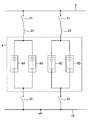
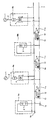
- FIG. 2 is a diagram showing an example of the configuration of the nickel metal hydride battery 8 of the present embodiment.
- the nickel metal hydride battery 8 is configured by connecting four units 8A to 8D in parallel.
- Each unit 8A to 8D may be constituted by the single battery module or the series battery module.
- high-speed circuit breakers 21 and 22 are provided as protection circuits when the batteries constituting the units 8A to 8D are short-circuited.
- the high-speed circuit breaker 21 is disposed on the feeder line 5 side
- the high-speed circuit breaker 22 is disposed on the wiring 15 side connected to the return line 7, and the reactor 23 is disposed between the nickel metal hydride battery 8 and the high-speed circuit breaker 21. Has been placed.
- the reactor 23 may be disposed between the high speed circuit breaker 22 and the nickel metal hydride battery 8.
- the high-speed circuit breakers 21 and 22 and the reactor 23 may be omitted in some cases. Moreover, you may provide what is called a discon (disconnector) instead of the high-speed circuit breakers 21 and 22.
- FIG. The discon does not have the ability to cut off the load current, but it is effective when performing maintenance work by opening the electric circuit.
- FIG. 3 is an SOC characteristic diagram showing a voltage change with respect to SOC (state of charge) of various batteries.
- Curve a shows the voltage change of the nickel metal hydride battery
- curve b shows the voltage change of the lead acid battery
- curve c shows the voltage change of the lithium ion battery
- curve d shows the voltage change of the electric double layer capacitor.
- the voltage change ( ⁇ V / ⁇ SOC) with respect to the SOC variation is about 0.1 for a nickel metal hydride battery, about 1.5 for a lead-acid battery, about 2 for a lithium ion battery, and about 3 for an electric double layer capacitor. That is, assuming the same voltage change, the nickel-metal hydride battery can be reduced in battery capacity to 1/15 of the lead-acid battery, 1/20 of the lithium ion battery, and 1/30 of the electric double layer capacitor. Accordingly, the battery size can be reduced accordingly.
- the nickel metal hydride battery indicated by the curve a has a characteristic that the SOC variation range S with respect to the voltage fluctuation is wider than other batteries. That is, in the nickel metal hydride battery, the battery voltage fluctuation is small relative to the SOC fluctuation. In comparison with this, in other batteries indicated by the curves b, c, d, the battery voltage varies greatly with respect to the SOC. For example, in terms of the median SOC, a nickel metal hydride battery can be used in almost all of the SOC range S when the median voltage is V 1 and the voltage fluctuation is within the range dV 1 . Battery capacity can be used effectively.
- the SOC can be used only in a narrow range, and the battery capacity cannot be used effectively.
- a lithium ion battery using such a voltage fluctuation and a voltage of the median value and V 3 is within a range dV 3
- the SOC is in the middle of the range S (for example, SOC is 40 to 60%)
- the nickel metal hydride battery 8 is directly connected to the feeder 5 as shown in FIG.
- the battery voltage varies greatly. That is, the nickel metal hydride battery can effectively use the battery capacity.
- the allowable fluctuation range of the feeder voltage is a range of about plus or minus 20% with respect to the nominal target voltage (for example, 750 V or 1500 V).
- the range in which the entire battery can be charged / discharged is limited to the range indicated by the SOC characteristics with respect to the fluctuation of the feeder voltage. That is, the power in the battery can be effectively utilized only within the range indicated by the SOC characteristics with respect to the fluctuation of the feeder voltage.
- nickel metal hydride batteries cover most of the SOC characteristics within the permissible fluctuation range of feeder voltage, the capacity in the battery is effectively used.
- the slope of the voltage change with respect to the SOC is large, so that the effective battery capacity is relatively limited within the range of about ⁇ 20% allowed for feeders. Less.
- secondary batteries such as lead-acid batteries or lithium ion batteries other than nickel metal hydride batteries are directly connected to feeders, a large number of batteries are required as a result, compared to nickel metal hydride batteries. Requires a large installation area, and further increases the equipment cost.
- FIG. 4 is a diagram showing an extracted nickel-hydrogen battery 8 and a substation portion 9a excluding the nickel-hydrogen battery.
- the substation 9a and the nickel metal hydride battery 8 are connected in parallel to the electric vehicle as a load.
- the feeding voltage of the feeder is V1
- the terminal voltage of the nickel metal hydride battery 8 is V2
- the internal resistance of the nickel metal hydride battery 8 is R2
- the impedance of the substation 9a is R1
- the internal resistance is 160 to 240 m ⁇ . If two units are connected in parallel to form a nickel metal hydride battery 8, the internal resistance is 80 to 120 m ⁇ , and if four units are connected in parallel to form a nickel metal hydride battery 8, the internal resistance is 40 to 60 m ⁇ .
- the nickel metal hydride battery 8 having a small internal resistance can be configured.
- the internal resistance of the lead-acid battery of the same capacity is about 10 times that of the nickel-metal hydride battery 8 compared to the nickel-metal hydride battery 8, and the internal resistance of the lithium-ion battery of the same capacity is about 2 times that of the nickel-metal hydride battery 8. Is double.
- the regenerative current from the electric vehicle flows more in the nickel metal hydride battery than in the lead storage battery or the lithium ion battery, and the amount of electricity charged in the secondary battery is large.
- the load current for accelerating the electric vehicle is shared according to the ratio of the impedance of the substation 9a and the internal resistance of the secondary battery, so that the internal resistance of the secondary battery is high.
- the amount of electricity stored in the secondary battery cannot be used sufficiently.
- the impedance of the substation of 2500 kW class is about 0.01 ⁇
- the load sharing between the substation 9 and the nickel metal hydride battery 8 is about 5: 1 considering the internal resistance of the nickel hydride battery 0.05 ⁇ .
- the load sharing is approximately 50: 1, and the lead-acid battery can sufficiently utilize the amount of electricity stored in the battery as compared with the nickel-metal hydride battery. Can not. The same applies to other types of secondary batteries other than lead-acid batteries.
- the nickel-metal hydride battery 8 has a smaller internal resistance than the other secondary batteries having the same capacity, so that a large amount of current flows and the amount of electricity that can be charged and discharged is large.
- the internal resistance can be reduced if a large number of them are connected in parallel, but a vast installation area is required, and more expensive equipment costs are required.
- This demonstration test was conducted by connecting a nickel-metal hydride battery 8 directly to a feeder 5 as shown in FIG.
- the voltage specification of the rectifying device 4 is 750 V
- the specification of the nickel metal hydride battery 8 is 750 V, 800 Ah.
- the rectifying device 4 and the nickel metal hydride battery 8 are connected to feeders that are connected to train lines for ascending vehicles and descending vehicles.
- the nickel metal hydride battery 8 used here has, for example, four units 8A to 8D of 750 V and 200 Ah connected in parallel as shown in FIG.
- Each of the units 8A to 8D is configured by connecting 20 battery modules of 37.5V and 200Ah in series.
- Each battery module is configured by connecting 30 unit batteries in series.
- the battery module for example, the third configuration example shown in FIGS. 12 to 14 described later is used, but another configuration example may be used.
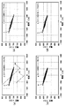
- FIG. 5 (a) shows the IV (current-voltage) characteristics of the nickel metal hydride battery 8 from 10 am to 11 am on the verification test day.
- FIG. 5B shows IV characteristics of the nickel metal hydride battery 8 from 11:00 am to 12:00 am on the same day.
- FIG. 5C shows IV characteristics of the nickel metal hydride battery 8 from 12:00 am to 13:00 on the same day.
- FIG. 5D shows IV characteristics of the nickel metal hydride battery 8 from 13:00 am to 14:00 on the same day.
- the current is negative, charging is indicated, and when the current is positive, discharging is indicated.
- FIGS. 5 (a) to 5 (d) The actual acquired data in this test is indicated by black dots in FIGS. 5 (a) to 5 (d). From these black spots, it can be seen that charging and discharging are repeated many times. As described above, the SOC changes when charge and discharge are repeated. As shown by the curve a in FIG. 3, the nickel-metal hydride battery has stable voltage characteristics in a wide range S of the SOC and has a small internal resistance. Therefore, the voltage fluctuation can be reduced as a whole.
- the lead storage battery when a lead storage battery is directly connected to the feeder wire instead of the nickel metal hydride battery 8, the lead storage battery has a large internal resistance, so in FIG. 5A, for example, an IV characteristic as indicated by a chain line k1. become.
- the voltage when the SOC fluctuates, the voltage also fluctuates greatly as shown by the curve b in FIG. 3, so that the IV characteristic fluctuates from the chain line k1 to, for example, the chain line k2.
- the IV characteristics fluctuate due to the fluctuation of the SOC as described above. Therefore, lead acid batteries are not suitable for use as a charge / discharge device.
- a lithium ion battery when the SOC varies, the voltage varies greatly as shown by the curve c in FIG. Therefore, a lithium ion battery is not suitable for being directly connected to a feeder and used as a charge / discharge device.
- the nickel-metal hydride battery 8 has a small internal resistance and a small voltage fluctuation due to the fluctuation of the SOC, it can be directly connected to the feeder 5 and used as a charging / discharging device.
- the battery capacity is set so that a range in which voltage fluctuation due to SOC fluctuation is small (for example, range S in FIG. 3) can be used.
- Lead storage batteries and lithium ion batteries are not suitable for practical use because if they have an extremely large capacity for direct connection to feeders, a very large installation area is required and the cost is very high.
- Nickel metal hydride battery 8 has low internal resistance and small voltage fluctuation due to SOC fluctuation. Therefore, when the electric vehicle performs acceleration, a large current is instantaneously required, and even if the nickel hydride battery is discharged, the voltage drop can be suppressed. At the same time, even if an instantaneous large current is generated by the regeneration of the electric vehicle, the increase in voltage can be suppressed by charging the nickel metal hydride battery. As described above, the electric railway power supply system including the nickel metal hydride battery can stabilize the feeder voltage. This could also be confirmed by the above-described demonstration test.
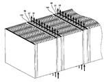
- Configuration Example of Battery Module Hereinafter, a configuration example of the battery module constituting the nickel metal hydride battery 8 used in the first embodiment of the present invention will be described. The configuration example of the battery module described below can be similarly applied to a nickel metal hydride battery of an electric railway power supply system according to a second embodiment of the present invention to be described later.
- FIG. 6A is a schematic cross-sectional configuration diagram of the battery module of the first configuration example
- FIG. 6B is a perspective view showing a part of the battery module.
- the battery module 40 has a structure in which six unit batteries 41 are connected in series as an example.
- Each unit battery 41 is composed of a positive electrode cell 43 and a negative electrode cell 44 which are made of a nonwoven fabric made of polypropylene fiber that transmits ions but does not transmit electrons, and is partitioned by a hydrophobic separator 42 that has not been subjected to a hydrophilic treatment.
- the left end wall of the positive electrode cell 43 of the left end unit battery 41 functions as a positive electrode current collector 45
- the right end wall of the negative electrode cell 44 of the right end unit battery 41 functions as a negative electrode current collector 46.
- the right side wall of the negative electrode cell 44 of the leftmost unit battery 41 and the left side wall of the positive electrode cell 43 of the rightmost unit battery 41 are made of a current collecting member 47 that also serves as a partition wall.
- a current collecting member 47 also serving as a partition wall is disposed between the four unit cells 41 located in the middle.
- the unit battery 41 from the left end to the unit battery 41 at the right end is connected in series via the current collecting member 47.
- Each positive electrode cell 43 and negative electrode cell 44 is filled with a KOH aqueous solution as a common electrolyte solution.
- the nickel hydroxide powder A is mixed in the KOH aqueous solution of the positive electrode cell 43
- the hydrogen-absorbing alloy powder B is mixed in the KOH aqueous solution of the negative electrode cell 44.
- the material of the current collecting member is a material such as nickel metal plate, nickel metal foil, carbon plate, nickel-plated iron, nickel-plated stainless steel, or nickel-plated carbon. It is possible to use a material that is not altered and does not allow ions to pass therethrough and has electrical conductivity.
- the negative electrode cell 44 is filled with the electrolyte solution charged with the hydrogen-absorbing alloy powder B as the negative electrode powder active material.
- the positive electrode cell 43 is filled with the nickel hydroxide powder A as the positive electrode powder active material.
- the electrolyte solution charged with is filled.
- the separator 42 is hydrophobic, when the electrolyte solution is filled in the negative electrode cell 44 and the positive electrode cell 43, the electrolyte solution is placed under a reduced pressure (internal pressure of about 1000 Pa or less). The method of pushing in is taken.
- a combination of the powder active material of the negative electrode and the positive electrode for example, a combination of a hydrogen absorbing alloy and nickel hydroxide can be used.
- a hydrogen absorbing alloy La0.3 (Ce, Nd) 0.15Zr0.05Ni3.8Co0.8Al0.5 can be cited.
- electrolyte solution for example, KOH aqueous solution, NaOH aqueous solution, LiOH aqueous solution or the like can be used.
- the separator 42 is made of a hydrophobic material that has not been hydrophilized. Since the separator 42 is used under the condition that the separator 42 is always in contact with the alkaline electrolyte solution, the hydrophobic material used for the separator 42 is preferably excellent in chemical resistance.
- polyolefin fibers such as polyethylene fibers and polypropylene fibers, polyphenylene sulfide fibers, porfluoroethylene fibers, polyamide fibers and the like are excellent in chemical resistance and can be preferably used as the separator 42. From these fibers, for example, a fiber sheet such as a woven fabric, a knitted fabric, a nonwoven fabric, a yarn lace, and a flat braided fabric can be formed.
- woven fabrics and non-woven fabrics are preferable because they have high tensile strength, excellent shape stability, and are not easily damaged during battery assembly.
- the woven fabric may be plain weave, satin weave, twill weave, or the like.
- the non-woven fabric for example, a fiber web formed by a card method, an air lay method, a spun bond method, a melt blow method, or the like is entangled by needle punching, water flow, etc. Alternatively, it can be obtained by a method of fusing by heat treatment and pressure treatment, or a method of adhering the fiber web with an adhesive.
- the woven fabric and the non-woven fabric are not limited to these.
- the oxygen cell 48 filled with high-pressure oxygen gas is passed through the pressure regulating valve 49 to the positive cell 43 and the negative cell 44 of each unit battery 41.
- opening and closing 52a, 52b, 52c, 52d, 52e and 52f oxygen gas is supplied to both the positive electrode cell 43 and the negative electrode cell 44, or only the positive electrode cell 43 or only the negative electrode cell 44.
- the gas and excess hydrogen gas remaining in the negative electrode cell 44 can be reacted to be converted into water. That is, the oxygen gas supplied to the negative electrode cell 44 reacts with excess hydrogen gas remaining in the negative electrode cell 44 to be converted to water, and the oxygen gas supplied to the positive electrode cell 43 passes through the separator 42 and passes through the negative electrode. It reacts with excess hydrogen gas remaining in the cell 44 and is converted to water.
- an oxygen cylinder 48 filled with high-pressure (20 kg / cm 2 ) oxygen gas is passed through a pressure regulating valve 49 and 2 kg / cm 2 oxygen.
- the battery manufacturers are generally often faced with the problem of how to deal with heat generated by battery reactions.
- the problem of heat generation cannot be ignored, and it is preferable that the battery with a sealed structure has an appropriate heat transfer structure.
- FIG. 7 is a diagram relating to an example of a cylindrical battery.
- a positive electrode active material sheet 61, an ion permeable separator 62, a negative electrode active material sheet 63, and an ion permeable separator 62 are sequentially stacked and wound into a spiral shape to form a cylindrical battery.
- the case 64 serves as a negative terminal
- the cap 65 serves as a positive terminal.
- FIG. 8 is a diagram relating to an example of a square battery.
- a square battery is configured by sequentially stacking a positive electrode active material sheet 71, an ion permeable separator 72, a negative electrode active material sheet 73, and an ion permeable separator 72.
- one end wall 74 is a positive electrode terminal
- the other end wall 75 is a negative electrode terminal.
- the side walls 76 and 77 are insulators.
- the structure shown in FIG. 7 needs to conduct heat in a direction (radial direction) perpendicular to the arrangement direction (circumferential direction) of the active material sheet and the separator, but it conducts heat well through the materials stacked in multiple layers. It is difficult to achieve this, rather, each layer is thought to play a role similar to thermal insulation.
- the separator which is a fiber or a porous plastic material having low thermal conductivity is laminated, the thermal conductivity is particularly low.
- the structure shown in FIG. 8 needs to conduct heat in a direction perpendicular to the arrangement direction (horizontal direction) of the active material sheet and the separator, but achieves good heat conduction through the materials stacked in multiple layers. It is difficult to do, rather, each layer is thought to play a role close to thermal insulation.
- the porous current collecting member 47 becomes the heat transfer member. Therefore, the heat generated by the battery reaction can be sufficiently dissipated from the current collecting member. Thereby, deterioration of the battery can be suppressed.
- the current collecting member 47 in addition to using the current collecting member 47 as a heat radiating member, it can also be used as a heat storage member. In other words, it is not preferable that the heat generated by the battery reaction is trapped in the sealed battery because the deterioration of the battery is promoted.
- the battery components are constant.
- the temperature range (about 25 ° C. to 50 ° C.). Therefore, instead of forcibly dissipating heat from the porous current collecting member 47, in some cases, in order to keep the battery component member at a certain temperature or higher, for example, about 25 ° C.
- a heat insulating material can be attached to the outer surface of the current collecting member 47.
- heat dissipation can be suppressed by not operating the fan when the battery component is at a certain temperature or lower.
- the current collecting member 47 which is a partition wall, has excellent conductivity, and has a current collecting member 47 made of a porous aluminum plate, and a positive electrode cell and a negative electrode cell partitioned by a separator, as shown in FIG. 6 (b).
- the unit battery 41 is closely connected. Therefore, not only electrons but also heat can be transmitted well through the current collecting member 47.
- the temperature of the thermometer installed inside the battery is 120% overcharged even after 2 hours.
- a metal plate such as an aluminum plate provided with a large number of through holes for flowing a coolant in the vertical direction may be used.
- a positive electrode terminal for external connection similar to a positive electrode terminal 94 shown in FIG. 10 described later is attached to the central portion of the positive electrode current collector 45, and the center of the negative electrode current collector 106 is attached.
- FIG. 9 is a perspective view showing a configuration in which the battery module 81 of the second configuration example is cooled by a fan that performs forced cooling and a wind tunnel (air circulation space).
- the battery module 81 includes an air circulation space 82 through which air flows. The air sucked by the intake fan 83a and the intake fan 83b is discharged to the outside through the lower air circulation space 82, the heat transfer space in the battery module 81, and the upper air circulation space 84.
- the arrows in FIG. 9 indicate the direction of air flow.
- FIG. 10A is a longitudinal sectional view of the battery module of the second configuration example.
- FIG.10 (b) is sectional drawing which shows the electrically-conductive member arrange
- FIG. 10C is a perspective view showing a conductive member disposed outside the positive electrode plate of a unit battery (described below) that constitutes the battery module of the second configuration example. Arrows other than the arrow x in FIG. 10A indicate the direction of air flow.
- the battery module 81 is formed by stacking six unit batteries as an example. Each unit battery is charged with an electrolyte solution between a positive electrode plate 85 which is a positive electrode current collector and a negative electrode plate 86 which is a negative electrode current collector, and an alkaline electrolyte between the positive electrode cell 85S and the negative electrode cell 86S. A separator 87 that does not change in quality, such as corrosion and does not transmit electrons, is interposed, and a positive electrode active material is inserted into the positive electrode cell 85S, and a negative electrode active material is inserted into the negative electrode cell 86S. It is the composition which consists of. Between the two adjacent unit cells, an air flow path 88 in the vertical direction is provided through which air sucked from the intake fan 83a and the intake fan 83b flows.
- the air flow path 88 is not provided over the entire portion where the positive electrode plate 85 and the negative electrode plate 86 face each other, but as shown in FIGS. 10 (b) and 10 (c). 85 and the central part of the negative electrode plate 86 are provided in the vertical direction. Conductive members 89 are disposed on both sides of the air flow path 88, and the positive electrode plate 85 and the negative electrode plate 86 are connected by the conductive member 89.
- the separator 87 for example, a woven or non-woven fabric such as tetrafluoroethylene resin, polyethylene, nylon, or polypropylene, or a membrane filter can be used.
- the conductive member 89 is a nickel metal plate such as a nickel-plated aluminum plate, a nickel metal foil, a carbon plate, nickel-plated iron, nickel-plated stainless steel, nickel-plated carbon, or the like in an alkaline electrolyte solution. It is possible to use a material that does not undergo alteration such as corrosion and does not allow ions to pass therethrough and is electrically conductive.
- Each unit battery is surrounded by insulating plates 93 and 92 above and below.
- the lower and upper air circulation spaces 82 and 84 are surrounded by insulating plates 90 and 91 on the lower and upper sides, respectively.
- a positive terminal 94 for external connection is attached to the central portion of the positive electrode plate 85 at the left end as shown in FIG.
- a negative terminal 95 for external connection is attached to the central portion of the negative electrode plate 86 at the right end as shown in FIG.
- the battery module 40 instead of the battery module 81, the battery module 40 having the porous current collecting member 47 shown in FIG. 6 may be used.
- a heat transfer plate 96 shown in FIG. 11 may be used.
- the heat transfer plate 96 is made of aluminum and nickel-plated, and a number of air flow paths 97 are provided in the vertical direction. This heat transfer plate 96 can be inserted between the positive electrode plate 85 and the negative electrode plate 86 in place of the conductive member 89 so that the air sucked by the intake fan 83a and the intake fan 83b can be circulated through the distribution path 9. .
- the heat transfer plate 96 is also a member for contacting the positive electrode plate 85 and the negative electrode plate 86 to electrically connect the positive electrode plate 85 and the negative electrode plate 86, and also has electrical conductivity.
- aluminum has a preferable property as the heat transfer plate 96 because it has a relatively low electrical resistance and a relatively high thermal conductivity, but has a drawback of being easily oxidized. Therefore, it is more preferable that the aluminum plate is nickel-plated as the heat transfer plate 96 because not only the oxidation is suppressed but also the contact resistance is lowered by the nickel plating.
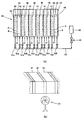
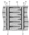
- FIG. 12 is a cross-sectional view of the battery module of the third configuration example.
- FIG. 13 is a diagram showing the flow direction of air in the heat transfer plate in the battery module of FIG. 12, and the insulating plates 107 and 108 shown in FIG. 12 are omitted.
- FIG. 14 is a diagram showing a heat transfer direction in the battery module of FIG.
- the battery module 98 is formed by stacking a plurality of unit batteries.
- the positive electrode current collector 99 and the negative electrode current collector 100 that are provided opposite to each other do not undergo alteration such as corrosion in an alkaline electrolyte, and have a bellows shape that transmits ions but does not transmit electrons.
- the separators 101 are alternately arranged in close proximity to both current collectors.
- a positive electrode sheet 103 containing a positive electrode active material together with the electrolyte solution 102 is disposed in a space defined by the bellows-shaped separator 101 and the positive electrode current collector 99, and the bellows-shaped separator 101 and the negative electrode current collector are disposed.
- a negative electrode sheet 104 containing a negative electrode active material together with the electrolyte solution 102 is disposed in a space partitioned by the body 100, and the positive electrode sheet 103 and the negative electrode sheet 104 are alternately incorporated with the separator 101 interposed therebetween.
- the positive electrode sheet 103 is in contact with the positive electrode current collector 99
- the negative electrode sheet 104 is in contact with the negative electrode current collector 100.
- a heat transfer plate 96 shown in FIG. 11 is inserted between two adjacent unit cells so as to be in contact with the positive electrode current collector 99 of one unit cell and the negative electrode current collector 100 of the other unit cell. Has been.
- the direction of the air flow path 97 of the heat transfer plate 96 coincides with the vertical direction of the positive electrode sheet 103 and the negative electrode sheet 104.
- the separator 101 is divided into a positive electrode cell and a negative electrode cell, and is divided by the separator 101 and the positive electrode current collector 99 to form the positive electrode sheet 103.
- the region in which the negative electrode sheet 104 is arranged is the positive electrode cell, and the region in which the negative electrode sheet 104 is divided by the separator 101 and the negative electrode current collector 100 is the negative electrode cell.
- the battery module 98 can be cooled by using the battery module 98 of the present configuration example instead of the battery module 81 of the second configuration example.
- a positive electrode current collector 99 and a negative electrode current collector 100 made of a metal having excellent conductivity and good thermal conductivity are in direct contact with the positive electrode sheet 103 and the negative electrode sheet 104, respectively.
- Each of the current collectors 99 and 100 is in contact with a heat transfer plate 96 that plays a role of electrically connecting the positive electrode current collector 99 and the negative electrode current collector 100. Accordingly, the heat generated as a result of the battery reaction with respect to the air flowing through the air flow path 97 of the heat transfer plate 96 along the direction indicated by the arrow in FIG. 13 follows the direction indicated by the arrow in FIG. Efficiently transmitted and released to the outside. In this way, the temperature of the battery module 98 is maintained in an appropriate range in which the battery reaction can be performed smoothly.
- a general positive electrode current collector 105 is provided at the end of the positive electrode, and a general negative electrode current collector 106 is provided at the end of the negative electrode. Insulating plates 107 and 108 are provided on the sides of the battery module 98.
- a positive electrode terminal similar to, for example, the positive electrode terminal 94 shown in FIG. 10 is attached to the central portion of the overall positive electrode current collector 105, and the same as the negative electrode terminal 95 shown in FIG. 10, for example, is attached to the central portion of the overall negative electrode current collector 106.
- a negative terminal is attached.
- the positive electrode sheet 103 is obtained, for example, by applying a paste obtained by adding a solvent to a positive electrode active material, a conductive filler, and a resin to form a plate and curing it.
- the negative electrode sheet 104 is obtained by, for example, applying a paste obtained by adding a solvent to a negative electrode active material, a conductive filler, and a resin, forming the paste on a substrate, and curing it.
- the positive electrode active material and the negative electrode active material all known active material materials can be used.
- As the conductive filler carbon fiber, carbon fiber nickel-plated, carbon particles, carbon particle nickel-plated, organic fiber nickel-plated, fibrous nickel, nickel particles, or nickel foil alone Or can be used in combination.
- thermoplastic resin having a softening temperature up to 120 ° C., a resin having a curing temperature from room temperature to 120 ° C., a resin that dissolves in a solvent having an evaporation temperature of 120 ° C. or less, a resin that dissolves in a solvent soluble in water, or Resins that are soluble in alcohol-soluble solvents can be used.
- substrate a metal plate having electrical conductivity such as a nickel plate can be used.
- the capacitor component is added to the battery to charge and discharge at high speed for a short time, and the battery bears the shortage. As a result, it is possible to improve the battery durability. is there. This is because the internal resistance of the capacitor component is small compared to the internal resistance of the battery, so when charging and discharging at high speed for a short time, the capacitor component is mainly charged and discharged, so the burden on the battery is reduced. .
- a method in which a substance having a large capacitor capacity is inserted between the separator and the positive electrode active material and between the separator and the negative electrode active material can be employed.
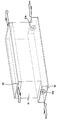
- a unit battery having a structure as shown in FIG. 15 can be employed.
- the positive electrode side is surrounded by the positive electrode current collector 111, the negative electrode side is surrounded by the negative electrode current collector 112, and the side portion is surrounded by the insulator 113.
- the cell surrounded by these is filled with the electrolyte solution.
- the cell does not undergo alteration such as corrosion in an alkaline electrolyte and does not transmit electrons, but is divided into a positive electrode cell 115 and a negative electrode cell 116 by an ion-permeable substantially bellows-shaped separator 114 that transmits ions. Yes.
- a substantially bellows-like polypropylene fiber non-woven fabric 117 containing a positive electrode active material that is in contact with the separator 114 is disposed.
- the non-woven fabric 117 is also in contact with the non-woven fabric 117 and is part of the positive electrode current collector 111.
- a molded body 118 made of a substantially bellows-like nickel foam containing a positive electrode active material in contact with each other is disposed.
- a non-woven fabric 119 having a substantially bellows-like polypropylene fiber containing a negative electrode active material that is in contact with the separator 114 is disposed.
- a molded body 120 made of a substantially bellows-like nickel foam containing a negative electrode active material in contact with the electrode is disposed.
- a substantially bellows-like polypropylene fiber nonwoven fabric 117 and a substantially bellows-like polypropylene fiber nonwoven fabric 119 correspond to capacitor components.
- the cycle life was 4000 cycles when the substantially bellows-like polypropylene fiber nonwoven fabric 117 and the substantially bellows-like polypropylene fiber nonwoven fabric 119 were removed, but as shown in FIG. 15.
- the cycle life in the case of having the substantially bellows-like nonwoven fabric 117 of polypropylene fibers and the nonwoven fabric 119 of substantially bellows-like polypropylene fibers exceeded 10,000 cycles.
- a battery module can be configured by stacking a plurality of unit batteries having the configuration shown in FIG.
- a plurality of unit cells having the configuration shown in FIG. 15 are connected in series via the conductive member 89 shown in FIG. 10 or the heat transfer plate 96 shown in FIG. It suffices to stack them.
- a battery module is configured by stacking a plurality of unit cells, and at that time, the positive cells and the negative cells are arranged in the same direction as the stacking direction (alignment direction) of the unit cells.
- a plate-shaped current collector (current collecting member 47 in FIG. 6, positive electrode plate 85 and negative electrode plate 86 in FIG. 6) is disposed between the positive electrode cell of one unit battery and the negative electrode cell of the other unit battery which are adjacent to each other.
- a conductive member 89 (see FIG. 10) that forms an air flow path 88 in the center between the current collectors (the positive electrode plate 85 and the negative electrode plate 86 in FIG. 10, the positive electrode current collector 99 and the negative electrode current collector 100 in FIG. 12). 10) or a heat transfer plate 96 (see FIG. 11) provided with a flow hole serving as an air circulation path 97 is inserted.
- the heat generated by the battery reaction can be efficiently taken into the refrigerant (for example, air) from the current collector and dissipated to the outside, and the cooling effect is increased.
- heat transfer medium air is used as the refrigerant (heat transfer medium), but a liquid such as water or oil may be used. Moreover, it is not limited to this, All the heat transfer media which consist of gas or liquid generally known as a heat transfer medium can be used.
- a plurality of unit cells are stacked to form a battery module.
- the positive cells and the negative cells are arranged so as to be aligned in the same direction as the stacking direction (alignment direction) of the unit batteries, and the ones adjacent to each other.
- the battery module is configured as in each of the configuration examples and the cooling structure is provided, so that heat generation due to the battery reaction can be suppressed, thereby suppressing deterioration of the battery and extending the life of the battery. Can be achieved. Moreover, the equivalent internal resistance of the battery module can be further reduced. Therefore, the life of the nickel metal hydride battery 8 can be extended, and the equivalent internal resistance can be further reduced.
- the electric railway power supply system has a configuration in which the nickel metal hydride battery 8 is directly connected to the feeder 5 and the wiring 15 in the substation 9.
- a very expensive charge / discharge control device such as a step-up / down chopper can be dispensed with, so that the configuration of the entire device can be simplified and the manufacturing cost can be reduced.
- there is no operation delay in the charge / discharge control device and the rapid charge / discharge characteristics are excellent, and the feeder voltage can be stabilized.
- the step-up / step-down chopper used as the charge / discharge control device is omitted, there is no possibility of generating harmonic noise that hinders the signal device.
- the electric railway power supply system according to the first embodiment of the present invention does not require a charge / discharge control device, its installation space is unnecessary.
- the nickel metal hydride battery has a high volumetric energy density, even a high capacity nickel metal hydride battery 8 using a large number of unit batteries does not require a large installation area.
- the size can be further reduced and the installation area can be reduced.
- the 750 V, 800 Ah nickel-metal hydride battery 8 used in the above-described demonstration test has a volume of 18 m 3 .
- the nickel metal hydride battery 8 has a low internal resistance, the amount of heat generated inside the battery is small, heat loss can be reduced, and the heat dissipation device of the battery itself can be reduced.
- the nickel-metal hydride battery has a capacitor effect, so even if it suddenly receives a sudden voltage rise change, or conversely releases a large current instantaneously, the entire battery is compared to other batteries. It is advantageous in that the voltage change can be made smooth.
- the capacitor effect of the nickel metal hydride battery 8 can be further enhanced.
- FIG. 16 is a schematic configuration diagram of an electric railway power supply system according to the second embodiment of the present invention.
- the nickel metal hydride battery 8 is installed in a substation 9 for electric railway.
- the nickel metal hydride battery 8 is installed at a place other than the substation 9 such as an intermediate point between the electric railway substation and the substation. Are installed.
- the battery module constituting the nickel metal hydride battery 8 used in the electric railway power supply system according to the second embodiment of the present invention is the battery constituting the nickel metal hydride battery 8 used in the first embodiment described above. It may be the same as the module.
- the power storage and supply devices 10 a and 10 b have a configuration in which the nickel metal hydride battery 8 is directly connected to the feeder 5.
- the nickel-metal hydride battery 8 is directly connected to the feeder 5, as in the first embodiment, the nickel-metal hydride battery 8 is connected to the feeder 5 without going through the charge / discharge control device. It is that.
- the nickel-metal hydride battery 8 has a positive external terminal connected to the feeder 5 and a negative external terminal connected to a return line (rail) 7. That is, the pair of external terminals of the nickel metal hydride battery 8 is connected to the feeder 5 and the return wire 7.
- the nickel metal hydride battery can be directly connected to the feeder line 5 and the return line 7 without requiring a charge / discharge control device because the voltage fluctuation with respect to the SOC is small.
- the power storage and supply devices 10a and 10b are installed at different locations from the premises of the electric railway substations (electric vehicle substations) 9a and 9b, and the nickel hydrogen batteries 8 of the power storage and supply devices 10a and 10b
- the locations 9a and 9b are directly connected to portions of the feeder 5 that are different from the connection portions of the wires 5.
- a nickel metal hydride battery 8 is directly connected to the feeder 5 at the intermediate point between the electric railway substation 9a and the electric railway substation 9b.
- the nickel metal hydride battery 8 is connected to the feeder 5 near the end 5e of the feeder 5 from the electric railway substation 9a closest to the end 5e of the feeder 5, or It is directly connected to the end 5e of the feeder wire 5.
- the regenerative power generated in the electric vehicles 11a, 11b, and 11c is the nickel metal hydride battery 8 installed in the power storage and supply devices 10a and 10b. Accumulated in.
- the electric power stored in the nickel metal hydride battery 8 is appropriately supplied to the electric vehicles 11a, 11b, and 11c according to the voltage state of the feeder line 5.
- the voltage of the feeder 5 is to be lower than the voltage of the nickel metal hydride battery 8 in the power storage and supply devices 10a and 10b, the nickel hydride battery 8 is discharged to the feeder 5 and the drop in feeder voltage can be suppressed. .
- the feeder voltage becomes higher than the voltage of the nickel metal hydride battery 8 in the power storage and supply devices 10a and 10b when the regenerative power is generated, the nickel metal hydride battery 8 is charged, and the rise of the feeder voltage can be suppressed. Thereby, regeneration revocation etc. are prevented and it is prevented that the driving energy of an electric vehicle is consumed wastefully.
- the feeder 5 since the feeder 5 has its own resistance, the voltage drop increases as the distance from the substation increases. That is, when an electric vehicle traveling far away from the substation accelerates and consumes a large amount of power, the voltage drop becomes larger, which may hinder the traveling of the electric vehicle. On the other hand, when the electric vehicle decelerates, the feeder voltage increases due to the regenerative power generated. At this time, due to the resistance of the feeder 5, the voltage rise of the feeder near the electric vehicle that has generated regenerative power tends to be larger than the voltage rise of the feeder near the substation rather than near the electric vehicle. There is a risk that regeneration will expire.
- the power storage and supply devices 10a and 10b are provided between the substation 9a and the substation 9b, or near the terminal end or the start end of the line.
- the distance from the power storage and supply devices 10a and 10b to the electric vehicle can be relatively shortened, and the voltage drop of the feeder voltage during the discharge from the nickel metal hydride battery 8 due to the resistance of the feeder 5 and the nickel hydride The fluctuation of the voltage rise of the feeder voltage when charging the battery 8 can be reduced.
- the power storage and supply devices 10a and 10b may be installed between substations as necessary, and may not be installed between all substations. For example, if the distance between substations is short, it may not be installed between the substations. Further, it may be installed at the end of the feeder as required, and may not be installed if the distance between the end of the feeder and the substation is short.
- the electric vehicle can be driven to the nearest station by supplying power from the power storage and supply devices 10a and 10b.
- the power storage and supply device 10a, 10b is used as a substation for a short time, the function of the substation can be stopped and maintenance of the substation can be performed.
- the interval between the substations can be increased and the number of substations can be reduced.
- the construction cost of the substation is great. It is also possible to abolish existing railway substations and install power storage and supply devices 10a and 10b to effectively use the remaining site.
- the following demonstration test shows that the power storage and supply devices 10a and 10b can replace the substation in this way.
- Verification Test Results A verification test of the electric railway power supply system according to the second embodiment of the present invention was performed. 17 (a) to 17 (d) are diagrams showing the results of the verification test.
- a nickel-metal hydride battery 8 is connected between the feeder 5 and the return line 7 so that it is connected in parallel with, for example, the rectifier 4 in an electric railway substation in a certain double track section in Japan.
- the power storage and supply device 10a and 10b having the nickel-metal hydride battery 8 By stopping the function of the power storage and supply device 10a and 10b having the nickel-metal hydride battery 8, the power storage and supply device 10a installed between twice the normal substation interval is used. 10b is confirmed.
- the voltage specification of the feeder is 750 V
- the specification of the nickel metal hydride battery 8 is 712.5 V, 800 Ah.
- the rectifier 4 and the nickel hydrogen battery 8 in a stopped state are connected to feeders that are connected to train lines for ascending vehicles and descending vehicles.
- the nickel metal hydride battery 8 used here has, for example, four units 8A to 8D connected in parallel as shown in FIG.
- Each of the units 8A to 8D is constituted by 19 battery modules of 37.5V and 200Ah connected in series.
- Each battery module is configured by connecting 30 unit batteries in series.
- FIG. 17A shows the IV (current-voltage) characteristics of the nickel metal hydride battery 8 from 5 am to 6 am on the verification test day.
- FIG. 17B shows the IV characteristics of the nickel metal hydride battery 8 from 6 am to 7 am on the same day.
- FIG. 17C shows the IV characteristics of the nickel metal hydride battery 8 from 7 am to 8 am on the same day.
- FIG. 17D shows the IV characteristics of the nickel metal hydride battery 8 from 8 am to 9 am on the same day.
- the current is negative, charging is indicated, and when the current is positive, discharging is indicated.
- the internal resistance is about 0.05 ⁇ on the straight lines e to h.
- the maximum voltage was 815V and the minimum voltage was 637V, and it was proved that it was within the allowable range of 900V to 600V for the feeder voltage of 750V even in the morning rush hour.
- Test results showed that battery power supply equipment could be an alternative to substation equipment.
- the nickel-metal hydride battery 8 is directly connected to the feeder 5 as in the first embodiment.
- an extremely expensive charge / discharge control device such as a step-up / down chopper can be dispensed with, the configuration of the entire device can be simplified and the manufacturing cost can be reduced.
- there is no operation delay in the charge / discharge control device and it is excellent in rapid charge / discharge characteristics, and the feeder voltage can be stabilized.
- the step-up / step-down chopper used as the charge / discharge control device is omitted, there is no possibility of generating harmonic noise that hinders the signal device.
- a nickel metal hydride battery 8 is directly connected to a feeder at a point far from the substation, for example, a feeder 5 between the substation and the substation, or an end 5e of the feeder corresponding to the end or start of the line.
- the power storage and supply devices 10a and 10b are configured.
- the nickel metal hydride battery is installed in the electric railway substation in the electric railway power supply system. Further, in the second embodiment of the present invention, in the electric railway power supply system, the nickel metal hydride battery is installed at a place other than the electric railway substation.
- the installation location of the nickel metal hydride battery is not limited to these.
- One nickel metal hydride battery may be installed in an electric railway substation, and another nickel metal hydride battery may be installed in a place other than the electric railway substation.
- the electric railway power supply system including the nickel metal hydride battery according to the present invention can be suitably used as an electric railway power supply system including a nickel metal hydride battery installed in an electric railway substation.
- the electric railway power supply system according to the present invention can be suitably used as an electric railway electric power supply system installed at a point distant from the electric railway substation.
Abstract
Priority Applications (5)
| Application Number | Priority Date | Filing Date | Title |
|---|---|---|---|
| JP2010500735A JP5174146B2 (ja) | 2008-02-29 | 2009-02-26 | 電気鉄道用電力供給システム |
| KR1020107020906A KR101165912B1 (ko) | 2008-02-29 | 2009-02-26 | 전기철도용 전력 공급 시스템 |
| CN2009801070920A CN101965275B (zh) | 2008-02-29 | 2009-02-26 | 电气化铁路用电力供给系统 |
| EP09715185.6A EP2255992A4 (fr) | 2008-02-29 | 2009-02-26 | Système d'alimentation pour chemin de fer électrique |
| US12/919,983 US8598739B2 (en) | 2008-02-29 | 2009-02-26 | Electric railway power-supply system |
Applications Claiming Priority (4)
| Application Number | Priority Date | Filing Date | Title |
|---|---|---|---|
| JP2008051409 | 2008-02-29 | ||
| JP2008-051409 | 2008-02-29 | ||
| JP2008202052 | 2008-08-05 | ||
| JP2008-202052 | 2008-08-05 |
Publications (1)
| Publication Number | Publication Date |
|---|---|
| WO2009107715A1 true WO2009107715A1 (fr) | 2009-09-03 |
Family
ID=41016102
Family Applications (1)
| Application Number | Title | Priority Date | Filing Date |
|---|---|---|---|
| PCT/JP2009/053552 WO2009107715A1 (fr) | 2008-02-29 | 2009-02-26 | Système d'alimentation pour chemin de fer électrique |
Country Status (8)
| Country | Link |
|---|---|
| US (1) | US8598739B2 (fr) |
| EP (1) | EP2255992A4 (fr) |
| JP (1) | JP5174146B2 (fr) |
| KR (1) | KR101165912B1 (fr) |
| CN (2) | CN101965275B (fr) |
| RU (1) | RU2465157C2 (fr) |
| TW (1) | TW201002550A (fr) |
| WO (1) | WO2009107715A1 (fr) |
Cited By (16)
| Publication number | Priority date | Publication date | Assignee | Title |
|---|---|---|---|---|
| WO2012111679A1 (fr) * | 2011-02-14 | 2012-08-23 | 株式会社 東芝 | Dispositif de batterie et procédé pour l'installer et le faire fonctionner |
| JP2012234696A (ja) * | 2011-04-28 | 2012-11-29 | Toyota Motor Corp | 電池システム |
| TWI422093B (zh) * | 2009-11-12 | 2014-01-01 | Kawasaki Heavy Ind Ltd | Battery system, electric railway power supply system and battery module |
| WO2014002717A1 (fr) * | 2012-06-25 | 2014-01-03 | 株式会社日立製作所 | Système de chemin de fer |
| JP2014040127A (ja) * | 2012-08-21 | 2014-03-06 | Mitsubishi Electric Corp | 駅舎電源装置 |
| CN103887567A (zh) * | 2014-04-21 | 2014-06-25 | 四川宝生新能源电池有限公司 | 纯电动大巴车镍氢电池组 |
| JP2014515916A (ja) * | 2011-03-31 | 2014-07-03 | アドゥミニストゥラドル・デ・インフラエストゥルクトゥラス・フェロビアリアス(アデイエフェ) | 電気鉄道システムからの電池の充電を制御するシステム及び方法 |
| JP2014131369A (ja) * | 2012-12-28 | 2014-07-10 | Kawasaki Heavy Ind Ltd | 電力制御システム |
| EP2317599A3 (fr) * | 2009-11-03 | 2014-11-05 | Delphi Technologies, Inc. | Bloc batterie à cellule prismatique avec canaux de refroidissement intégrés |
| JP2015012682A (ja) * | 2013-06-28 | 2015-01-19 | 三洋電機株式会社 | 電源装置 |
| JP2015157607A (ja) * | 2014-02-25 | 2015-09-03 | 株式会社東芝 | 蓄電池装置および蓄電池装置の制御方法 |
| JP2015168334A (ja) * | 2014-03-07 | 2015-09-28 | 株式会社日立製作所 | 電力貯蔵式電圧安定化装置およびその制御方法 |
| US10020653B2 (en) | 2013-11-28 | 2018-07-10 | Mitsubishi Electric Corporation | Station-building power supply device |
| JP2018134922A (ja) * | 2017-02-21 | 2018-08-30 | 株式会社明電舎 | 冷却水流量制御方法及び電力変換装置 |
| JP2019158752A (ja) * | 2018-03-15 | 2019-09-19 | 三菱ロジスネクスト株式会社 | バッテリ残存容量表示システム、及び、状態量表示方法 |
| WO2021100112A1 (fr) * | 2019-11-19 | 2021-05-27 | 株式会社堤水素研究所 | Système d'alimentation électrique en cc |
Families Citing this family (27)
| Publication number | Priority date | Publication date | Assignee | Title |
|---|---|---|---|---|
| EP2412563A4 (fr) * | 2009-03-24 | 2015-04-01 | Kawasaki Heavy Ind Ltd | Dispositif régulateur de courant électrique pour système d'alimentation en courant électrique |
| KR101232218B1 (ko) * | 2011-03-04 | 2013-02-12 | 한국철도기술연구원 | 도시 철도의 회생 에너지 저장 장치 |
| JP5791363B2 (ja) * | 2011-05-10 | 2015-10-07 | 株式会社小松製作所 | 自走式ケーブル中継台車 |
| JP5523639B2 (ja) * | 2012-01-12 | 2014-06-18 | 三菱電機株式会社 | 電気車制御装置 |
| KR101383142B1 (ko) * | 2012-07-23 | 2014-04-09 | 한국철도기술연구원 | 대용량 플라이휠 에너지 저장 시스템 및 그의 병렬 운전 제어 방법 |
| JP6039982B2 (ja) * | 2012-09-28 | 2016-12-07 | 株式会社日立製作所 | 電力需給システム |
| BR112015007005A2 (pt) * | 2012-10-19 | 2017-07-04 | Mitsubishi Electric Corp | dispositivo inversor para vagões ferroviários, transformador para vagões ferroviários, e, método de fabricação de transformador para vagões ferroviários |
| JP6082937B2 (ja) * | 2012-11-30 | 2017-02-22 | 株式会社日立製作所 | 電鉄き電線の制御装置およびシステム |
| JP6081178B2 (ja) * | 2012-12-14 | 2017-02-15 | 株式会社日立製作所 | 電力変換器および電力変換器の制御方法 |
| EP3007925B1 (fr) * | 2013-06-14 | 2019-03-27 | Hedgehog Applications B.V. | Procédé et système permettant l'utilisation de l'énergie du freinage par récupération des véhicules ferroviaires |
| CN103448573B (zh) * | 2013-07-29 | 2015-11-18 | 华北电力大学(保定) | 一种双向互动式电气化铁路高压直流牵引供电系统 |
| JP5735061B2 (ja) * | 2013-08-12 | 2015-06-17 | 株式会社東芝 | 電車給電システム |
| WO2017060444A1 (fr) * | 2015-10-07 | 2017-04-13 | Abb Schweiz Ag | Agencement et procédé pour transformer une tension |
| US10324146B2 (en) * | 2016-01-12 | 2019-06-18 | Life Services, LLC | Method and apparatus for multi-part body coil |
| DE102016214051A1 (de) * | 2016-07-29 | 2018-02-01 | Siemens Aktiengesellschaft | Verfahren zur Stromversorgung und Stromversorgung für an einer Bahnstrecke angeordnete Bahnbetriebselemente |
| DE102017105728A1 (de) * | 2017-03-16 | 2018-09-20 | Fraunhofer-Gesellschaft zur Förderung der angewandten Forschung e.V. | Vorrichtung zur Energieversorgung eines elektrischen Betriebsnetzes |
| CN106953332B (zh) * | 2017-05-02 | 2019-07-16 | 中国矿业大学 | 基于不控整流和阶梯波合成逆变的电气化铁路同相供电方案 |
| CN107176063B (zh) * | 2017-06-06 | 2023-03-24 | 西南交通大学 | 一种电气化铁路外部电网供电构造 |
| RU2653848C1 (ru) * | 2017-07-12 | 2018-05-15 | Открытое Акционерное Общество "Научно-Исследовательский И Проектно-Конструкторский Институт Информатизации, Автоматизации И Связи На Железнодорожном Транспорте" | Вторичный источник электропитания радиомодема малой мощности |
| DE102018105300A1 (de) * | 2018-03-08 | 2019-09-12 | Paul Vahle Gmbh & Co. Kg | Gleichstromübertragung über stromschienen |
| FR3086896B1 (fr) | 2018-10-08 | 2022-04-22 | Alstom Transp Tech | Installation de stockage de l'energie electrique issue du freinage d'un ou plusieurs vehicules ferroviaires et systeme de stockage associe |
| US20220050074A1 (en) * | 2020-04-30 | 2022-02-17 | Richard Postrel | Instant Early Stage Disease Detection by Decoding Organic Compound Signatures |
| CN112140890B (zh) * | 2020-09-28 | 2022-03-29 | 中车资阳机车有限公司 | 一种混合动力机车的多支路动力电池系统控制方法 |
| CN112202160B (zh) * | 2020-10-20 | 2022-06-03 | 国网四川省电力公司电力科学研究院 | 一种直挂母线式储能控制系统及控制方法 |
| CN112350377B (zh) * | 2021-01-11 | 2021-04-13 | 西南交通大学 | 一种同相牵引供电发电系统及控制方法 |
| PL439601A1 (pl) * | 2021-11-23 | 2023-05-29 | Dmowska-Andrzejuk Danuta | Sposób i układ zasilania trakcji elektrycznej prądu stałego |
| KR102488872B1 (ko) | 2022-06-22 | 2023-01-18 | 주식회사 창해전기 | 전기철도차량용 전력공급시스템 |
Citations (6)
| Publication number | Priority date | Publication date | Assignee | Title |
|---|---|---|---|---|
| JP2000341874A (ja) | 1999-05-25 | 2000-12-08 | Sumitomo Electric Ind Ltd | 電気鉄道用充放電装置 |
| JP2001260719A (ja) | 2000-03-16 | 2001-09-26 | Railway Technical Res Inst | 電鉄用直流き電システム |
| JP2002002334A (ja) | 2000-06-20 | 2002-01-09 | Meidensha Corp | 電鉄用直流電源設備 |
| JP2005206111A (ja) * | 2004-01-26 | 2005-08-04 | Toshiba Corp | 直流電圧給電装置 |
| JP2007066647A (ja) * | 2005-08-30 | 2007-03-15 | Toyota Motor Corp | 電池冷却構造および電池モジュール |
| WO2008099609A1 (fr) * | 2007-02-14 | 2008-08-21 | Kawasaki Jukogyo Kabushiki Kaisha | Cellule et sa structure de transfert de chaleur |
Family Cites Families (13)
| Publication number | Priority date | Publication date | Assignee | Title |
|---|---|---|---|---|
| US2675490A (en) * | 1949-06-28 | 1954-04-13 | Cipel | Direct current feed device for electric apparatus |
| US4476947A (en) * | 1981-06-26 | 1984-10-16 | Chevron Research Company | Electric car and roadway system |
| JP3428336B2 (ja) * | 1996-12-26 | 2003-07-22 | 松下電器産業株式会社 | 角形密閉式蓄電池 |
| DE19823233A1 (de) * | 1998-05-25 | 1999-12-02 | Asea Brown Boveri | Vorrichtung zur Speisung von gleichstrombetriebenen Fahrzeugen |
| CN2366975Y (zh) * | 1999-04-01 | 2000-03-01 | 石家庄开发区高达科技开发有限公司 | 复合蓄电池 |
| JP2001035488A (ja) * | 1999-07-26 | 2001-02-09 | Honda Motor Co Ltd | ニッケル水素電池の製造方法 |
| KR100658255B1 (ko) * | 2001-09-19 | 2006-12-14 | 카와사키 주코교 카부시키 카이샤 | 고출력형 삼차원 전지 |
| RU2259284C2 (ru) * | 2003-02-18 | 2005-08-27 | Быкадоров Александр Леонович | Тяговая подстанция постоянного тока со сверхпроводниковым индуктивным накопителем энергии |
| RU40264U1 (ru) * | 2004-05-05 | 2004-09-10 | Открытое акционерное общество "Авиационная электроника и коммуникационные системы" | Комбинированная система питания транспортного средства |
| JP4432675B2 (ja) * | 2004-08-25 | 2010-03-17 | 株式会社日立製作所 | 電力変換装置 |
| KR100659366B1 (ko) | 2004-12-24 | 2006-12-19 | 한국철도기술연구원 | 도시철도의 회생전력 저장시스템 |
| DK1855344T3 (da) * | 2006-05-11 | 2011-09-26 | Hoppecke Batterien Gmbh & Co Kg | Akkumulatorindretning |
| US7531270B2 (en) * | 2006-10-13 | 2009-05-12 | Enerdel, Inc. | Battery pack with integral cooling and bussing devices |
-
2009
- 2009-02-26 US US12/919,983 patent/US8598739B2/en not_active Expired - Fee Related
- 2009-02-26 WO PCT/JP2009/053552 patent/WO2009107715A1/fr active Application Filing
- 2009-02-26 RU RU2010139876/11A patent/RU2465157C2/ru not_active IP Right Cessation
- 2009-02-26 JP JP2010500735A patent/JP5174146B2/ja active Active
- 2009-02-26 CN CN2009801070920A patent/CN101965275B/zh not_active Expired - Fee Related
- 2009-02-26 CN CN201310146129.9A patent/CN103253155B/zh not_active Expired - Fee Related
- 2009-02-26 EP EP09715185.6A patent/EP2255992A4/fr not_active Withdrawn
- 2009-02-26 KR KR1020107020906A patent/KR101165912B1/ko active IP Right Grant
- 2009-02-27 TW TW98106542A patent/TW201002550A/zh not_active IP Right Cessation
Patent Citations (6)
| Publication number | Priority date | Publication date | Assignee | Title |
|---|---|---|---|---|
| JP2000341874A (ja) | 1999-05-25 | 2000-12-08 | Sumitomo Electric Ind Ltd | 電気鉄道用充放電装置 |
| JP2001260719A (ja) | 2000-03-16 | 2001-09-26 | Railway Technical Res Inst | 電鉄用直流き電システム |
| JP2002002334A (ja) | 2000-06-20 | 2002-01-09 | Meidensha Corp | 電鉄用直流電源設備 |
| JP2005206111A (ja) * | 2004-01-26 | 2005-08-04 | Toshiba Corp | 直流電圧給電装置 |
| JP2007066647A (ja) * | 2005-08-30 | 2007-03-15 | Toyota Motor Corp | 電池冷却構造および電池モジュール |
| WO2008099609A1 (fr) * | 2007-02-14 | 2008-08-21 | Kawasaki Jukogyo Kabushiki Kaisha | Cellule et sa structure de transfert de chaleur |
Non-Patent Citations (1)
| Title |
|---|
| See also references of EP2255992A4 |
Cited By (25)
| Publication number | Priority date | Publication date | Assignee | Title |
|---|---|---|---|---|
| EP2317599A3 (fr) * | 2009-11-03 | 2014-11-05 | Delphi Technologies, Inc. | Bloc batterie à cellule prismatique avec canaux de refroidissement intégrés |
| TWI422093B (zh) * | 2009-11-12 | 2014-01-01 | Kawasaki Heavy Ind Ltd | Battery system, electric railway power supply system and battery module |
| US9461292B2 (en) | 2009-11-12 | 2016-10-04 | Kawasaki Jukogyo Kabushiki Kaisha | Battery system, power supply system for electric railcars, and battery module |
| JP2012166646A (ja) * | 2011-02-14 | 2012-09-06 | Toshiba Corp | 蓄電装置とその設置・運用方法 |
| CN103347733A (zh) * | 2011-02-14 | 2013-10-09 | 株式会社东芝 | 蓄电装置及其设置·运用方法 |
| WO2012111679A1 (fr) * | 2011-02-14 | 2012-08-23 | 株式会社 東芝 | Dispositif de batterie et procédé pour l'installer et le faire fonctionner |
| US9312717B2 (en) | 2011-02-14 | 2016-04-12 | Kabushiki Kaisha Toshiba | Electric energy storage device and installation-operation method thereof |
| CN103347733B (zh) * | 2011-02-14 | 2015-11-25 | 株式会社东芝 | 蓄电装置及其设置和运用方法 |
| JP2014515916A (ja) * | 2011-03-31 | 2014-07-03 | アドゥミニストゥラドル・デ・インフラエストゥルクトゥラス・フェロビアリアス(アデイエフェ) | 電気鉄道システムからの電池の充電を制御するシステム及び方法 |
| JP2012234696A (ja) * | 2011-04-28 | 2012-11-29 | Toyota Motor Corp | 電池システム |
| JP2014004914A (ja) * | 2012-06-25 | 2014-01-16 | Hitachi Ltd | 鉄道システム |
| CN104379397A (zh) * | 2012-06-25 | 2015-02-25 | 株式会社日立制作所 | 铁道系统 |
| WO2014002717A1 (fr) * | 2012-06-25 | 2014-01-03 | 株式会社日立製作所 | Système de chemin de fer |
| JP2014040127A (ja) * | 2012-08-21 | 2014-03-06 | Mitsubishi Electric Corp | 駅舎電源装置 |
| JP2014131369A (ja) * | 2012-12-28 | 2014-07-10 | Kawasaki Heavy Ind Ltd | 電力制御システム |
| JP2015012682A (ja) * | 2013-06-28 | 2015-01-19 | 三洋電機株式会社 | 電源装置 |
| US10020653B2 (en) | 2013-11-28 | 2018-07-10 | Mitsubishi Electric Corporation | Station-building power supply device |
| JP2015157607A (ja) * | 2014-02-25 | 2015-09-03 | 株式会社東芝 | 蓄電池装置および蓄電池装置の制御方法 |
| JP2015168334A (ja) * | 2014-03-07 | 2015-09-28 | 株式会社日立製作所 | 電力貯蔵式電圧安定化装置およびその制御方法 |
| CN103887567A (zh) * | 2014-04-21 | 2014-06-25 | 四川宝生新能源电池有限公司 | 纯电动大巴车镍氢电池组 |
| JP2018134922A (ja) * | 2017-02-21 | 2018-08-30 | 株式会社明電舎 | 冷却水流量制御方法及び電力変換装置 |
| JP2019158752A (ja) * | 2018-03-15 | 2019-09-19 | 三菱ロジスネクスト株式会社 | バッテリ残存容量表示システム、及び、状態量表示方法 |
| WO2021100112A1 (fr) * | 2019-11-19 | 2021-05-27 | 株式会社堤水素研究所 | Système d'alimentation électrique en cc |
| JPWO2021100112A1 (ja) * | 2019-11-19 | 2021-11-25 | 株式会社堤水素研究所 | 直流電力システム |
| JP7168243B2 (ja) | 2019-11-19 | 2022-11-09 | 株式会社堤水素研究所 | 直流電力システム |
Also Published As
| Publication number | Publication date |
|---|---|
| RU2465157C2 (ru) | 2012-10-27 |
| US8598739B2 (en) | 2013-12-03 |
| JP5174146B2 (ja) | 2013-04-03 |
| US20110043038A1 (en) | 2011-02-24 |
| EP2255992A4 (fr) | 2014-09-24 |
| CN103253155A (zh) | 2013-08-21 |
| TW201002550A (en) | 2010-01-16 |
| CN101965275A (zh) | 2011-02-02 |
| RU2010139876A (ru) | 2012-04-10 |
| TWI370065B (fr) | 2012-08-11 |
| JPWO2009107715A1 (ja) | 2011-07-07 |
| EP2255992A1 (fr) | 2010-12-01 |
| CN101965275B (zh) | 2013-11-06 |
| KR20110000633A (ko) | 2011-01-04 |
| KR101165912B1 (ko) | 2012-07-19 |
| CN103253155B (zh) | 2016-02-10 |
Similar Documents
| Publication | Publication Date | Title |
|---|---|---|
| JP5174146B2 (ja) | 電気鉄道用電力供給システム | |
| Liu et al. | Energy storage devices in electrified railway systems: A review | |
| Hoque et al. | Battery charge equalization controller in electric vehicle applications: A review | |
| Kumar et al. | A comparative review on power conversion topologies and energy storage system for electric vehicles | |
| JP5322685B2 (ja) | 蓄電型電車の給電システム | |
| Vazquez et al. | Energy storage systems for transport and grid applications | |
| JP4415874B2 (ja) | 交通システムの充放電方法 | |
| KR101174190B1 (ko) | 전지 및 그 전열구조 | |
| CN102447086B (zh) | 蓄电模块及蓄电装置 | |
| JP5658450B2 (ja) | 電池システム | |
| Konishi et al. | Fixed energy storage technology applied for DC electrified railway | |
| JP2009284690A (ja) | 電池駆動車両 | |
| JP5421558B2 (ja) | 蓄電装置駆動電車の給電システム | |
| Ogura et al. | Test results of a high capacity wayside energy storage system using Ni-MH batteries for DC electric railway at New York City Transit | |
| JP2012080628A (ja) | 電気自動車の充電システム | |
| Bhatt et al. | An assessment of batteries form battery electric vehicle perspectives | |
| JP2011126298A (ja) | 電気鉄道用電力供給システム | |
| KR102346306B1 (ko) | 축전 시스템, 차량, 및 기계 설비 | |
| CN111532291A (zh) | 轨道交通无网自行走双路输出蓄电池与双向充电机系统 | |
| JP2010184538A (ja) | 低床式電気車両 | |
| JP7202471B2 (ja) | 高速磁気浮上列車の電力供給電池及び電力供給システム | |
| Mi et al. | Design of On-Board Energy Storage Systems for Regenerative Braking Energy Recovery in Urban Rail Transit | |
| Gopakumar et al. | Conventional Applications of Supercapacitors | |
| KR20080047638A (ko) | 전기자동차의 전원 시스템 |
Legal Events
| Date | Code | Title | Description |
|---|---|---|---|
| WWE | Wipo information: entry into national phase |
Ref document number: 200980107092.0 Country of ref document: CN |
|
| 121 | Ep: the epo has been informed by wipo that ep was designated in this application |
Ref document number: 09715185 Country of ref document: EP Kind code of ref document: A1 |
|
| WWE | Wipo information: entry into national phase |
Ref document number: 2010500735 Country of ref document: JP |
|
| NENP | Non-entry into the national phase |
Ref country code: DE |
|
| REEP | Request for entry into the european phase |
Ref document number: 2009715185 Country of ref document: EP |
|
| WWE | Wipo information: entry into national phase |
Ref document number: 2009715185 Country of ref document: EP |
|
| ENP | Entry into the national phase |
Ref document number: 20107020906 Country of ref document: KR Kind code of ref document: A |
|
| WWE | Wipo information: entry into national phase |
Ref document number: 6042/CHENP/2010 Country of ref document: IN |
|
| WWE | Wipo information: entry into national phase |
Ref document number: 2010139876 Country of ref document: RU |
|
| WWE | Wipo information: entry into national phase |
Ref document number: 12919983 Country of ref document: US |