WO2009104587A1 - 車両用格納シート - Google Patents
車両用格納シート Download PDFInfo
- Publication number
- WO2009104587A1 WO2009104587A1 PCT/JP2009/052662 JP2009052662W WO2009104587A1 WO 2009104587 A1 WO2009104587 A1 WO 2009104587A1 JP 2009052662 W JP2009052662 W JP 2009052662W WO 2009104587 A1 WO2009104587 A1 WO 2009104587A1
- Authority
- WO
- WIPO (PCT)
- Prior art keywords
- seat
- storage
- urging
- locking
- rotation direction
- Prior art date
- Legal status (The legal status is an assumption and is not a legal conclusion. Google has not performed a legal analysis and makes no representation as to the accuracy of the status listed.)
- Ceased
Links
Images


Classifications
-
- B—PERFORMING OPERATIONS; TRANSPORTING
- B60—VEHICLES IN GENERAL
- B60N—SEATS SPECIALLY ADAPTED FOR VEHICLES; VEHICLE PASSENGER ACCOMMODATION NOT OTHERWISE PROVIDED FOR
- B60N2/00—Seats specially adapted for vehicles; Arrangement or mounting of seats in vehicles
- B60N2/02—Seats specially adapted for vehicles; Arrangement or mounting of seats in vehicles the seat or part thereof being movable, e.g. adjustable
- B60N2/22—Seats specially adapted for vehicles; Arrangement or mounting of seats in vehicles the seat or part thereof being movable, e.g. adjustable the back-rest being adjustable
- B60N2/235—Seats specially adapted for vehicles; Arrangement or mounting of seats in vehicles the seat or part thereof being movable, e.g. adjustable the back-rest being adjustable by gear-pawl type mechanisms
- B60N2/2356—Seats specially adapted for vehicles; Arrangement or mounting of seats in vehicles the seat or part thereof being movable, e.g. adjustable the back-rest being adjustable by gear-pawl type mechanisms with internal pawls
- B60N2/2362—Seats specially adapted for vehicles; Arrangement or mounting of seats in vehicles the seat or part thereof being movable, e.g. adjustable the back-rest being adjustable by gear-pawl type mechanisms with internal pawls rotatably movable
-
- B—PERFORMING OPERATIONS; TRANSPORTING
- B60—VEHICLES IN GENERAL
- B60N—SEATS SPECIALLY ADAPTED FOR VEHICLES; VEHICLE PASSENGER ACCOMMODATION NOT OTHERWISE PROVIDED FOR
- B60N2/00—Seats specially adapted for vehicles; Arrangement or mounting of seats in vehicles
- B60N2/005—Arrangement or mounting of seats in vehicles, e.g. dismountable auxiliary seats
- B60N2/015—Attaching seats directly to vehicle chassis
- B60N2/01508—Attaching seats directly to vehicle chassis using quick release attachments
- B60N2/01516—Attaching seats directly to vehicle chassis using quick release attachments with locking mechanisms
- B60N2/01583—Attaching seats directly to vehicle chassis using quick release attachments with locking mechanisms locking on transversal elements on the vehicle floor or rail, e.g. transversal rods
-
- B—PERFORMING OPERATIONS; TRANSPORTING
- B60—VEHICLES IN GENERAL
- B60N—SEATS SPECIALLY ADAPTED FOR VEHICLES; VEHICLE PASSENGER ACCOMMODATION NOT OTHERWISE PROVIDED FOR
- B60N2/00—Seats specially adapted for vehicles; Arrangement or mounting of seats in vehicles
- B60N2/24—Seats specially adapted for vehicles; Arrangement or mounting of seats in vehicles for particular purposes or particular vehicles
- B60N2/30—Non-dismountable or dismountable seats storable in a non-use position, e.g. foldable spare seats
- B60N2/3002—Non-dismountable or dismountable seats storable in a non-use position, e.g. foldable spare seats back-rest movements
- B60N2/3004—Non-dismountable or dismountable seats storable in a non-use position, e.g. foldable spare seats back-rest movements by rotation only
- B60N2/3009—Non-dismountable or dismountable seats storable in a non-use position, e.g. foldable spare seats back-rest movements by rotation only about transversal axis
- B60N2/3011—Non-dismountable or dismountable seats storable in a non-use position, e.g. foldable spare seats back-rest movements by rotation only about transversal axis the back-rest being hinged on the cushion, e.g. "portefeuille movement"
-
- B—PERFORMING OPERATIONS; TRANSPORTING
- B60—VEHICLES IN GENERAL
- B60N—SEATS SPECIALLY ADAPTED FOR VEHICLES; VEHICLE PASSENGER ACCOMMODATION NOT OTHERWISE PROVIDED FOR
- B60N2/00—Seats specially adapted for vehicles; Arrangement or mounting of seats in vehicles
- B60N2/24—Seats specially adapted for vehicles; Arrangement or mounting of seats in vehicles for particular purposes or particular vehicles
- B60N2/30—Non-dismountable or dismountable seats storable in a non-use position, e.g. foldable spare seats
- B60N2/3038—Cushion movements
- B60N2/304—Cushion movements by rotation only
- B60N2/3045—Cushion movements by rotation only about transversal axis
- B60N2/305—Cushion movements by rotation only about transversal axis the cushion being hinged on the vehicle frame
-
- B—PERFORMING OPERATIONS; TRANSPORTING
- B60—VEHICLES IN GENERAL
- B60N—SEATS SPECIALLY ADAPTED FOR VEHICLES; VEHICLE PASSENGER ACCOMMODATION NOT OTHERWISE PROVIDED FOR
- B60N2/00—Seats specially adapted for vehicles; Arrangement or mounting of seats in vehicles
- B60N2/24—Seats specially adapted for vehicles; Arrangement or mounting of seats in vehicles for particular purposes or particular vehicles
- B60N2/30—Non-dismountable or dismountable seats storable in a non-use position, e.g. foldable spare seats
- B60N2/3072—Non-dismountable or dismountable seats storable in a non-use position, e.g. foldable spare seats on a lower level of a multi-level vehicle floor
- B60N2/3075—Non-dismountable or dismountable seats storable in a non-use position, e.g. foldable spare seats on a lower level of a multi-level vehicle floor stowed in recess
-
- B—PERFORMING OPERATIONS; TRANSPORTING
- B60—VEHICLES IN GENERAL
- B60N—SEATS SPECIALLY ADAPTED FOR VEHICLES; VEHICLE PASSENGER ACCOMMODATION NOT OTHERWISE PROVIDED FOR
- B60N2/00—Seats specially adapted for vehicles; Arrangement or mounting of seats in vehicles
- B60N2/24—Seats specially adapted for vehicles; Arrangement or mounting of seats in vehicles for particular purposes or particular vehicles
- B60N2/30—Non-dismountable or dismountable seats storable in a non-use position, e.g. foldable spare seats
- B60N2/3072—Non-dismountable or dismountable seats storable in a non-use position, e.g. foldable spare seats on a lower level of a multi-level vehicle floor
- B60N2/3077—Non-dismountable or dismountable seats storable in a non-use position, e.g. foldable spare seats on a lower level of a multi-level vehicle floor stowed in the luggage compartment
- B60N2/3079—Non-dismountable or dismountable seats storable in a non-use position, e.g. foldable spare seats on a lower level of a multi-level vehicle floor stowed in the luggage compartment in a recess
-
- B—PERFORMING OPERATIONS; TRANSPORTING
- B60—VEHICLES IN GENERAL
- B60N—SEATS SPECIALLY ADAPTED FOR VEHICLES; VEHICLE PASSENGER ACCOMMODATION NOT OTHERWISE PROVIDED FOR
- B60N2/00—Seats specially adapted for vehicles; Arrangement or mounting of seats in vehicles
- B60N2/24—Seats specially adapted for vehicles; Arrangement or mounting of seats in vehicles for particular purposes or particular vehicles
- B60N2/30—Non-dismountable or dismountable seats storable in a non-use position, e.g. foldable spare seats
- B60N2/3088—Non-dismountable or dismountable seats storable in a non-use position, e.g. foldable spare seats characterised by the mechanical link
- B60N2/309—Non-dismountable or dismountable seats storable in a non-use position, e.g. foldable spare seats characterised by the mechanical link rods
-
- B—PERFORMING OPERATIONS; TRANSPORTING
- B60—VEHICLES IN GENERAL
- B60N—SEATS SPECIALLY ADAPTED FOR VEHICLES; VEHICLE PASSENGER ACCOMMODATION NOT OTHERWISE PROVIDED FOR
- B60N2/00—Seats specially adapted for vehicles; Arrangement or mounting of seats in vehicles
- B60N2/24—Seats specially adapted for vehicles; Arrangement or mounting of seats in vehicles for particular purposes or particular vehicles
- B60N2/32—Seats specially adapted for vehicles; Arrangement or mounting of seats in vehicles for particular purposes or particular vehicles convertible for other use
- B60N2/36—Seats specially adapted for vehicles; Arrangement or mounting of seats in vehicles for particular purposes or particular vehicles convertible for other use into a loading platform
Definitions
- the present invention relates to a storage seat for a vehicle, and more particularly to a storage seat for a vehicle with improved operability.
- a vehicle storage seat For example, a rear end portion of a seat cushion constituting a vehicle seat is supported on a front side of a storage recess (storage recess) on a vehicle body floor so as to be rotatable in the front-rear direction.
- a storage recess storage recess
- the vehicle seat is rotated rearward and stored in the storage recess in a state where the seat back is laid down on the cushion.
- the pivot shafts provided on the left and right sides of the rear end portion of the seat cushion are made to move the pivots of the seat cushion by the brackets provided on both the left and right front sides of the storage recess.
- the sheet By supporting the rear end portion so as to be rotatable in the front-rear direction, the sheet can be stored in the storage recess.
- the seat installation (return) operation load is reduced by attaching a spiral spring that urges the support portion in the seat cushion installation direction (return rotation direction).
- the operation load in the reverse rotation direction cannot be reduced.
- the damping damper is not attached, there is an inconvenience that it is difficult to realize an operational feeling that gives a sense of security because the rotational speed at the time of return and storage is fast.
- an object of the present invention is to provide a storage seat for a vehicle that reduces the operation load and the rotational speed in both the return and storage operations, and improves the sense of security during seat operation and the merchantability of the seat. Is to provide.
- the problem is that the first seat support means for rotatably supporting one end of the seat cushion, and the seat cushion can be laid down via the reclining means.
- the first seat support means for rotatably supporting the one end side of the seat cushion, and the first seat support means are attached to the first seat support means, and at least one side of the storage rotation direction and the return rotation direction.
- a storage seat for a vehicle having an urging means capable of urging the seat cushion on the vehicle body floor side with a predetermined angle of the seat cushion and an end portion that is always locked to the seat cushion side. Since the urging force applied to the seat cushion at a predetermined angle can be changed at a predetermined angle, the rotation speed can be appropriately reduced along with the reduction of the operation load. Can be adjusted.
- the urging means includes a plurality of urging springs having different predetermined angles. More specifically, as in claim 3, it is more preferable that the urging spring is composed of a plurality of urging springs having the same urging direction. Thus, by having a plurality of urging springs having different predetermined angles and the same urging direction, the urging force can be changed in several steps according to the rotation angle.
- the urging means includes one or more urging springs whose urging direction is one of the retracting rotation direction and the return rotation direction, and the urging direction is the retracting rotation. It is preferable to have one or more urging springs on the other side of the moving direction and the return rotation direction.
- the urging means includes one or more urging springs whose urging direction is one of the storage rotation direction and the return rotation direction, and the urging direction is the storage rotation direction and the return rotation.
- One or more urging springs on the other side of the direction so that the urging force can be rotated with respect to any rotation direction of the storage rotation direction and the return rotation direction. It can be changed in several stages depending on the situation.
- the biasing means is a first biasing spring that is biased in the return rotation direction with the other end being locked to the vehicle body floor at a first predetermined angle.
- a second biasing spring that is latched on the vehicle body floor side at a second predetermined angle and can be biased in the return rotation direction, and on the vehicle body floor side at a third predetermined angle.
- a third biasing spring that is locked at the other end and can be biased in a return rotation direction, wherein the first predetermined angle is 0 °, and the second predetermined angle is: It is preferable that the third predetermined angle is located in an angle range of 20 ° to 30 °, and the third predetermined angle is located in an angle range of 50 ° to 60 °.
- the urging means includes the first urging spring having the other end portion locked to the vehicle body floor side at the first predetermined angle and capable of urging in the return rotation direction, and the second predetermined angle.
- the other end is locked to the vehicle body floor side, the second biasing spring that can be biased in the return rotation direction, and the other end portion is locked to the vehicle body floor side at a third predetermined angle, and the return rotation
- the storage seat for a vehicle according to claim 1 in order to change the urging force applied to the seat cushion at a predetermined angle, the rotational speed is appropriately adjusted together with the reduction of the operation load, and the sense of security at the time of seat operation is improved.
- An improved vehicular storage seat can be provided.
- the urging force is changed in several steps according to the rotation angle by using the urging spring that is locked at the other end portion at different predetermined angles. Therefore, it is possible to provide a storage seat for a vehicle that can be operated smoothly and has improved safety during operation.
- the urging force can be changed in several steps according to the rotation angle in any of the storage rotation direction and the return rotation direction.
- the biasing force and the rotation speed can be appropriately changed according to the rotation angle. It is possible to provide a storage seat for a vehicle that is appropriately adjusted to improve a sense of security during seat operation.
- FIG. 1 is a schematic perspective view of a seat frame according to an embodiment of the present invention. It is an expansion explanatory view of the sheet support part concerning one embodiment of the present invention. It is a related figure of the rotation angle and torque in the 1st example about the sheet support part concerning one embodiment of the present invention. It is a related figure of a rotation angle and torque in the 2nd example about a sheet support part concerning one embodiment of the present invention.
- FIG. 2 is an II cross-sectional explanatory diagram of a link mechanism according to an embodiment of the present invention. It is a schematic explanatory drawing of the latching
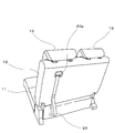
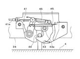
- FIG. 1 is a schematic side view of a rear portion of a vehicle equipped with a storage seat for a vehicle
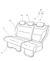
- FIG. 2 is a front perspective view of the storage seat for a vehicle
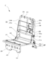
- FIG. 4 is a schematic perspective view of the seat frame
- FIG. 5 is an enlarged explanatory view of the seat support portion
- FIG. 6 is a relationship diagram of the rotation angle and torque in the first embodiment regarding the seat support portion
- FIG. 7 is a relationship diagram of the rotation angle and torque in the second embodiment relating to the seat support portion
- FIG. 8 is a relationship diagram of the rotation angle and torque in the third embodiment relating to the seat support portion
- FIG. 9 is a link mechanism.
- FIG. 1 is a schematic side view of a rear portion of a vehicle equipped with a storage seat for a vehicle
- FIG. 2 is a front perspective view of the storage seat for a vehicle
- FIG. 4 is a schematic perspective view of the seat frame
- FIG. 5 is an enlarged explanatory view of the seat support portion
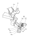
- FIG. 10 is a cross-sectional explanatory view taken along the line II of the link mechanism
- FIG. 11 is a schematic explanatory view of the locking portion of the front leg
- FIG. 12 is a schematic explanatory view of the link mechanism when the seat back is lying down
- FIG. I is a sectional view taken along the line II-II of the link mechanism
- FIG. 16 is an explanatory diagram showing an operation procedure during the storage operation of the vehicle storage seat
- FIG. 16 is an operation explanatory diagram of the link mechanism during the storage operation of the vehicle storage seat
- FIG. 17 is an operation procedure when the vehicle storage seat is returned.
- FIG. 18 is an operation explanatory view of the link mechanism at the time of the return operation of the storage seat for the vehicle.
- the vehicle equipped with the seat S according to the present embodiment includes three rows of seats arranged in series in the front-rear direction, and is configured so that the third row of seats can be stored.
- a storage recess 5 as a storing means for storing the seat S is provided in the vehicle body floor 4.
- a floor carpet (not shown) is laid over the entire surface of the vehicle body floor 4.
- the seat S has three seats on the left and right, and is composed of a two-seat right seat S1 positioned on the right side of the traveling direction of the vehicle and a one-seat left seat S2.
- the description of the right / left side indicating the direction is for the traveling direction of the vehicle.
- the right sheet S1 is collectively described as the sheet S for convenience in the following description example.
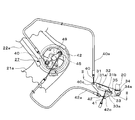
- the seat S includes a seat cushion 11, a seat back 12, headrests 13 and 13, and a front leg portion 14. Further, as shown in FIG. 3, from the back side of the seat back 12, a strap 20 as an operation means for storing and returning the seat S is extended outward from the strap outlet 20a.
- the reclining lock release mechanism and the leg lock release mechanism operating means for operating the storage seat for the vehicle at the time of storing and returning are integrated as one strap 20. Yes.
- the strap 20 is an operating means that is operated at the time of storing and returning the seat S, and is configured by a wide, flexible belt having a length of about 1 m so that the operation by the passenger is easy. Since the operation of storing and returning the sheet S can be performed by the pulling operation of the strap 20, the operation load can be reduced as compared with the operation by the lever. In a state where the seat S is not stored and returned, a part of the strap 20 is hooked on the back surface of the seat back 12 with a planar fastener.
- the strap 20 as the operation means is configured in a belt shape, but may be formed in a string shape or a tension lever shape.
- the seat frame F of the seat S shown in FIG. 4 includes a seat cushion frame 21 constituting the seat cushion 11, a seat back frame 22 constituting the seat back 12, and a front leg frame 24.
- the cushion frame 21 and the seat back frame 22 are connected via a reclining mechanism 27, and the seat cushion frame 21 and the vehicle body floor 4 side are connected via seat support portions 25 and 26.
- a pillar of a headrest frame (not shown) is disposed on the upper portion of the seat back frame 22 via a pillar support portion 23.
- the seat cushion frame 21 constitutes the seat cushion 11 that is covered by a cushion pad, a skin, etc. (not shown) and supports the occupant from below.
- the front side of the seat cushion frame 21 is supported by the front leg frame 24 on the vehicle body floor 4 side.
- back frame support portions 21 a and 21 a connected to the seat back frame 22 are disposed at the rear end portion of the seat cushion frame 21.
- the rear end portion side of the seat cushion frame 21 is supported by the seat support portions 25 and 26 so as to be rotatable in the front-rear direction.
- the seat back frame 22 constitutes a seat back 12 that is covered by a cushion pad (not shown) and supports the back of the occupant from the rear, and is a substantially rectangular frame in this embodiment. More specifically, the seat back frame 22 includes two side frames 22a and 22a extending in the vertical direction and spaced apart from each other in the left-right direction, and a substantially rectangular shape sandwiched between the side frames 22a and 22a. And a central frame 22b which is a frame body. The seat back frame 22 and the seat cushion frame 21 are provided with a storage locking mechanism 70.
- the lower end portions of the side frames 22a and 22a are connected to the back frame support portions 21a and 21a via a reclining mechanism 27 serving as a reclining means.
- a substantially plate-like back plate 28 is disposed inside the central frame 22b, which is a frame body, along a surface that supports the back of the occupant, and a link mechanism 30 described later is provided on the back plate 28. It has been.
- a strap outlet 20a is provided above the central frame 22b.
- the front leg frame 24 is covered with a cover material (not shown) to form the front leg 14 as the second seat support means, and supports the front side of the seat cushion frame 21 to the vehicle body floor 4 side. Connected.
- the front leg frame 24 is supported at the upper part on the front side of the seat cushion frame 21 so as to be pivotable in the front-rear direction.
- a lower part of the front leg frame 24 is connected to a leg striker 44 provided on the vehicle body floor 4 side. Locking claws 43, 43 that are detachably connected are arranged in two places.
- this embodiment it is set as the structure which arrange
- the seat support portions 25 and 26 as the first seat support means are configured as a pair of left and right, and the left and right are respectively rotating shafts 25a and 26a as shaft members attached to the left and right of the rear end portion side of the seat cushion frame 21.
- rotating shaft brackets 25b and 26b as vehicle body side brackets that rotatably support the rotating shafts 25a and 26a on the vehicle body floor side 4.
- Spiral springs 46, 47, 48 that urge the seat cushion 11 in the rotational direction are attached to the seat support 26 on one side of the left and right seat supports 25, 26.
- the urging spring is provided only on one side of the seat support portions 25 and 26, but the urging means may be attached to either side, and the urging spring is attached to both sides. It is good also as a structure.
- FIGS. 5 and 6 show a first embodiment relating to the sheet support portion 26.
- FIG. First, the configuration of the sheet support portion 26 will be described with reference to FIG.
- the pivot shaft bracket 26b of the seat support portion 26 is provided with an urging spring.
- the biasing spring is composed of three spiral springs 46, 47, 48 arranged in parallel.
- the spiral springs 46, 47, and 48 as urging springs are attached to the rotation shaft 26a on the inner end (inner hook) side so that the sheet S side can be urged in the forward rotation direction (return rotation direction). It has been. Therefore, the spiral springs 46, 47, and 48 rotate together with the rotation shaft 26a.
- the outer end portions (outer hooks) 46a, 47a, and 48a are arranged so as to be sequentially engaged with the engagement pins 26c on the rear side of the rotation shaft bracket 26b according to the rotation angle of the seat cushion 11. The hook position has been adjusted.
- each of the spiral springs 46, 47, and 48 will be described. Since the outer hook 46a of the spiral spring 46 is locked to the locking pin 26c even when the seat cushion 11 is installed (rotation angle 0 °), the seat cushion 11 is always urged in the return direction. The number of turns of the spiral spring 47 is adjusted so that the outer hook 47a of the spiral spring 47 is locked to the locking pin 26c in a state in which the seat cushion 11 is rotated in the 25 ° storage rotation direction from the installed state. . Therefore, the seat cushion 11 can be urged in the return direction on the retracting rotation side with respect to the angle to be locked.
- the number of turns of the spiral spring 48 is adjusted so that the outer hook 48a of the spiral spring 48 is locked to the locking pin 26c in a state where the seat cushion 11 is rotated in the retracted rotation direction by 55 ° from the installed state. . Therefore, the seat cushion 11 can be urged in the return direction on the retracting rotation side with respect to the angle to be locked.
- the outer hook 46a of the spiral spring 46 is engaged with the rotation shaft bracket 26b side.
- the angle to be stopped is 0 °.
- the spiral spring 47 is 25 ° and the spiral spring 48 is 55 °.
- the urging angle ranges of the respective springs are 0 to 180 ° for the spiral spring 46, 25 to 180 ° for the spiral spring 47, and 55 to 180 ° for the spiral spring 48.
- the angle at which the outer hooks 47a, 48a of the spiral springs 47, 48 are locked to the rotating shaft bracket 26b side is not limited to the above-mentioned angle, and the same effect can be obtained in a certain angle range. Can be obtained.
- the spiral spring 47 can be arbitrarily set within a range of 10 ° to 40 °, preferably 20 ° to 30 °
- the spiral spring 48 can be arbitrarily set within a range of 40 ° to 70 °, preferably 50 ° to 60 °.
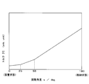
- the rotation angle s indicates the rotation angle of the seat cushion 11, and the installation state of the seat cushion 11 (seat S) is 0 ° and the storage state is 180 °.
- in FIG. 6 is the absolute value of the urging force T in one of the rotating directions by the urging spring, and represents the magnitude of the urging force that does not take the urging direction into consideration.
- the urging force actually applied to the seat cushion 11 is an integrated value (synthetic torque) of the urging forces T of the spiral springs 46, 47, and 48. Since the spiral springs 46, 47, and 48 have different urging ranges, these combined torques are bent as shown in FIG. First, the spiral spring 46 has a biasing force in the entire angle range. Since the spiral spring 47 exerts an urging force at an angle of 25 ° or more, the torque of the spiral spring 47 is added to the torque of the spiral spring 46 in the rotation angle range of 25 ° to 180 °. Furthermore, since the spiral spring 48 exerts an urging force at an angle of 55 ° or more, the torque of the spiral spring 48 is added to the combined torque of the spiral spring 46 and the spiral spring 47 in the rotation angle range of 55 ° to 180 °. become.
- the three spiral springs 46, 47, 48 can be used in an angular range that requires a large urging force immediately after the start of the operation. Since the urging force is exhibited, the operation load can be reduced. Further, after the middle stage of the return operation, the urging spring that exerts the urging force is reduced, so that the urging force is weakened and an increase in the rotation speed can be suppressed.
- the three spiral springs 46, 47, and 48 are used for biasing.
- the number of springs having different biasing angles the number of stages in which the biasing force changes is increased.
- a torque characteristic that rises in a quadratic curve with respect to the rotation angle can be obtained.
- the spiral springs 46, 47, and 48 have different numbers of turns, the same spring is used for other spring specifications such as plate thickness and plate width, but the specifications of each spring are different. By doing so, the biasing force can be adjusted. For example, by changing the plate pressure or the plate width of the spiral spring 46 to a large one, the urging force immediately after the return operation can be increased and the operation load can be greatly reduced.
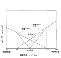
- FIG. 7 shows the relationship between the rotation angle and torque in the second embodiment relating to the seat support portion 26.
- one urging spring for urging in the return rotation direction and the retracting rotation direction is provided.
- the spring urging in the return rotation direction is disposed so as to be locked to the rear side of the rotation shaft bracket 26b at a rotation angle of 45 °, so that the rotation angle is 45 ° to 180 °. The force is exerted by.
- the spring urging in the retracting rotation direction is arranged to be locked to the front side of the rotation axis bracket 26b at a rotation angle of 135 °, the urging force is applied at a rotation angle of 0 ° to 135 °.
- the spring biased in the return rotation direction can obtain a larger torque than the spring biased in the storage rotation direction. I am using something.
- a strong urging force can be obtained in the movement start operation immediately after the operation, regardless of the operation in either the storing or returning directions.
- the urging direction by the urging spring is reversed at the neutral angle at which the integrated value of the torque T of the urging spring becomes 0, an increase in the rotation speed can be suppressed.
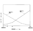
- FIG. 8 shows the relationship between the rotation angle and the torque in the third embodiment relating to the seat support portion 26.
- the configuration of the first embodiment shown in FIGS. 5 and 6 is also provided in the retracting rotation direction, and the return rotation side and the retracting rotation side are provided on the seat support portion 26.
- Three springs (6 in total) are attached to each of the springs.
- the biasing spring to the retracting rotation side is attached with a biasing force smaller than that of the return rotation side.
- a configuration may be adopted in which an urging spring to the return rotation side is attached to the seat support portion 26 and an urging spring to the storage rotation side is attached to the seat support portion 25 side.
- the seat cushion 11 can be flipped up by releasing the lock on the vehicle body floor 4 (storage recess 5) side.
- the operation load can be further reduced by the flip-up, and the safety during the operation is improved because it is visually recognized that the switch rotates in the flip-up direction.
- the link mechanism 30 is connected to the strap 20 that is operated when the seat S is retracted and returned, and in conjunction with the operation of the strap 20 and the state of the seat S, the rotation of the reclining mechanism 27, the front leg 14 and the vehicle body floor. 4 is provided on the back plate 28 as described above.
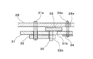
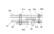
- the link mechanism 30 includes a first link member 31, a second link member 32, and a third link member 33 that are pivotally supported, and each link member includes A power transmission member is connected. Depending on the state between the power transmission members and the operation between the link members, they are configured to operate in conjunction with each other. Moreover, as a power transmission member, the reclining release wire 40 connected to the reclining mechanism 27, the strap 20, and the leg release wire 41 connected to the locking claw 43 of the front leg 14 (front leg frame 24). And a cancel wire 42 for detecting the lying state (folded state) of the seat back 12.
- the first link member 31 is a substantially inverted triangular flat member in the left-right direction, and a reclining release wire 40 as a power transmission member in each of the locking portions 34a, 40c disposed on both end sides,
- the strap 20 is locked via the strap connecting member 34.
- the first shaft portion 31a provided between the locking portions 40c and 34a is rotatably supported on the back plate 28. Further, an arc-shaped long hole 31b is formed between the first shaft portion 31a and the locking portion 34a so as to draw a part of a concentric circle of a second shaft portion 33a described later.
- the reclining release wire 40 locked to the first link member 31 and the other end side of the strap 20 will be described below. As shown in FIG. 12, the other end side of the reclining release wire 40 that is locked to the locking portion 40 c on the end side of the first link member 31 is guided by the reclining release cable 40 a, and the seat back 12. It is connected to a reclining mechanism 27 as a reclining means for releasing the rotational locking state.
- the reclining mechanism 27 is a mechanism in which when the reclining release wire 40 is pulled to the link mechanism 30 side by the operation of the link mechanism 30, the reclining mechanism 27 is released from the locked state to turn the seat back 12. It is.
- the other end side of the strap 20 connected to the first link member 31 via the strap connecting member 34 is seat backed from a strap outlet 20a provided on the back surface of the seat back 12 so that an operation by an occupant is easy. 12 are extended outward. Power (operating force of the occupant) can be transmitted to the first link member 31 in conjunction with the operation of the strap 20 by the occupant. That is, when the strap 20 is pulled, the first link member 31 is rotated and the locking of the reclining mechanism 27 is released.
- the second link member 32 is a substantially rectangular member and is disposed on the first link member 31.
- the end portion side to which the reclining release wire 40 is attached is pivotally supported by the first shaft portion 31a so as to be rotatable coaxially with the first link member 31, and a locking projection 35 described later is provided on the other end portion side.
- abuts is formed.
- a locking portion 41c is formed between the first shaft portion 31a and the locking recess 32b. The locking portion 41c locks the leg release wire 41.
- leg release wire 41 locked to the second link member 32 The other end side of the leg release wire 41 locked to the second link member 32 will be described below.
- the other end portion side of the leg release wire 41 locked to the locking portion 41c of the second link member 32 is guided by the leg release cable 41a and serves as a leg lock release mechanism as an engagement / disengagement means. It is connected.
- the leg part unlocking mechanism is formed in the front leg part 14.
- the claw 43 rotates about the locking claw rotating shaft 43a, the locking with the leg striker 44 on the vehicle body floor 4 side is released, and the seat cushion 11 becomes rotatable in the front-rear direction.
- the locking claw 43 is constantly biased by a biasing spring 45 in a direction in which the locking state with the leg striker 44 is maintained.
- the third link member 33 is a substantially rectangular member, and is disposed between the first link member 31 and the back plate 28, and the central portion is located on the first link member 31 side by the second shaft portion 33 a. Is pivotally supported by the shaft. A cancel wire 42 is locked to the lower end side of the third link member 33 via a locking portion 42c.
- a locking projection 35 as a cylindrical locking portion is formed on the upper end side, and this locking projection 35 is inserted through an arc-shaped long hole 31 b formed in the first link member 31.
- the second link member 32 is locked so as to rotate together with the first link member 31 by coming into contact with the locking recess 32 b of the second link member 32.
- the locking protrusion 35 is formed to have an outer diameter slightly smaller than the width of the long hole 31b.
- the long hole 31b is one of the concentric circles of the second shaft portion 33a as described above. Since the third link member 33 is rotated, the locking projection 35 is configured to move along the long hole 31b. The other end side of the cancel wire 42 that is locked to the third link member 33 will be described below.
- the other end portion side of the cancel wire 42 locked to the locking portion 42c of the third link member 33 is guided by the cancel cable 42a, and the side frame 22a and the back frame support portion 21a.
- the locking rib 49 is a member provided in the reclining mechanism 27 and is attached so as to rotate together with the side frame 22a. That is, in the present embodiment, the other end portion of the cancel wire 42 is locked to the locking rib 49.
- the other end side of the cancel wire 42 is configured such that the locking rib 49 pulls the locking portion 42c formed on the third link member 33 via the cancellation wire 42 in a state where the seat back 12 is lying down.
- the third link member 33 is rotated to function as a detection unit. That is, the reclining means has the reclining mechanism 27 and the detection means.
- a locking rib 49 that is locked to the other end side of the cancel wire 42 is formed in the reclining mechanism 27, but the cancellation is performed in a state where the seat back 12 is lying down with respect to the seat cushion 11.
- Other locking portions may be used as long as the wire 42 is operated.
- the reclining mechanism 27 may be formed at a site separated from the reclining mechanism 27.
- the reclining unit is configured to include the reclining mechanism 27 and the detecting unit at a site separated from each other.
- the second link member 32 In a state where the third link member 33 is not rotating, the second link member 32 is locked to the first link member 31 by the locking projection 35, and the first link member 31 is rotated. Accordingly, the leg release wire 41 can be pulled by rotating.
- the locking projection 35 fixed to the third link member 33 moves along the long hole 31b. Due to the movement of the locking projection 35, the locking recess 32b does not come into contact with the locking projection 35, so that the rotation locking between the first link member 31 and the second link member 32 is released.
- An urging spring 45 is provided on the side of the locking release mechanism (the other end side of the link mechanism 30) to which the reclining release wire 40 and the leg release wire 41 are connected, and the locked state
- the reclining release wire 40 and the leg release wire 41 are always urged in the direction to be held. For this reason, in a state where the occupant is not operating the strap 20, the first link member 31 and the second link member 32 also link the link mechanism 30 in a direction in which the strap 20 is always pulled downward via the strap connecting member 34. Is turned.
- the locking portion 34a of the strap connecting member 34 provided on the first link member 31 pivotally supports the strap connecting member 34 on the first link member 31 so that the strap connecting member 34 can rotate, and the other end side is a back plate.
- the guide hole 28a is formed in the guide hole 28a. Since the guide hole portion 28a is formed in an arc shape so as to draw a part of the concentric circle of the first shaft portion 31a, the locking portion 34a is guided along with the rotation of the first link member 31. The inside of the hole 28a can be moved. Moreover, the upper and lower limits of the rotation amount of the first link member 31 can be set by adjusting the length of the guide hole portion 28a.
- the reclining release cable 40a for guiding the reclining release wire 40 and the leg release wire 41, and the end members 40b and 41b that are the ends of the leg release cable 41a on the link mechanism 30 side are not formed on the back plate 28. It is fixed by the illustrated locking member.
- An end member 42b that is an end of the cancel cable 42a that guides the cancel wire 42 on the link mechanism 30 side is fixed to the first link member 31 by a locking member (not shown).
- FIG. 14 is an enlarged explanatory view of the storage locking mechanism 70.
- the storage locking mechanism 70 is a locking portion for holding the sheet S in the state of being stored in the storage recess 5, and is provided on the back side of the storage striker 74 provided at the bottom of the storage recess 5 and the seat back 12.
- the locking claw 73 is locked.
- the storage locking mechanism 70 includes a storage locking release wire 71 for operating the locking claw 73, a biasing spring 45 that biases the locking claw 73 to a side that holds the locking claw 73, and a grip 76 as a locking release means. And a storage link member 75 that connects the grip 76 and the storage lock release wire 71.
- the sheet S When the sheet S is stored, it is locked by pressing the sheet S against the storage recess 5. That is, the inclined hooking claw tip 73b comes into contact with the storage striker 74, and the hooking claw 73 rotates around the hooking claw rotation shaft 73a to a position where it can be locked with the storage striker 74. Further, to release the lock, the lock between the storage recess 5 and the seat back 12 is released by pulling the grip 76 provided on the seat cushion 11 side upward. By pulling the grip 76, the storage locking release wire 71 is pulled via the storage link member 75, and the locking claw 73 is rotated in the locking release direction.
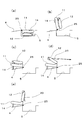
- FIG. 15A shows a state in which the strap 20 is pulled rearward with the seat installed. When the strap 20 is pulled backward by the occupant, the locking of the reclining mechanism 27 is released.
- FIG. 15B shows a state in which the locking claw 43 of the front leg 14 is unlocked. That is, the locking claw 43 of the front leg portion 14 is unlocked, and the seat S can be rotated rearward.
- FIG. 15C and FIG. 15D show a state in which the rearward rotation of the sheet S is advanced.
- the center of gravity of the sheet S exceeds the middle point of rotation, and thereafter, it is rotated rearward by its own weight to reach the retracted state.
- the rearward rotation speed of the sheet S is reduced by the spiral springs 46, 47, 48 attached to the sheet support portion 26, and the impact generated when storing in the storage recess 5 is mitigated.
- the front leg 14 is folded toward the seat cushion 11 by its own weight as the seat S rotates.
- FIG. 15E shows the storage state of the sheet S.
- the storage striker 74 provided at the bottom of the storage recess 5 and the locking claw 73 provided on the back surface of the seat back 12 are stored in the storage locking mechanism 70. It is in the state locked by.
- the storage locking mechanism 70 is locked by pressing the sheet S against the storage recess 5. In this state, the opening of the storage recess 5 becomes a flat surface integrated with the back surface of the seat cushion 11, and a wide cargo space is secured.
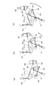
- FIG. 16A shows a state of the link mechanism 30 when the seat S is installed (see FIG. 15A), and is a stage before the strap 20 is operated by the occupant.
- the state of the link mechanism 30 is assumed to be the original position.
- FIG. 16B shows the state of the link mechanism 30 when the reclining mechanism 27 is unlocked (FIG. 15B), and is a stage where the strap 20 is slightly pulled backward. Since the first link member 31 rotates in the direction pulled by the operation of the strap 20, the reclining release wire 40 is pulled with the rotation, and the locking of the reclining mechanism 27 is released. At this time, since the seat back 12 is standing with respect to the seat cushion 11, the cancel wire 42 is not pulled, and the second link member 32 rotates together with the first link member 31 to form the leg portion. The release wire 41 is also pulled. However, the locking claw 43 that connects the front leg portion 14 and the vehicle body floor 4 side is set so as not to be released by the pulling amount in this state, and the locking of the leg portion is maintained.
- FIG. 16C shows the state of the reclining mechanism 27 and the link mechanism 30 when the locking claw 43 of the front leg portion 14 is released (FIGS. 15C and 15D). Is in a state of being further pulled.
- the first link member 31 is also rotated greatly. With this rotation, the reclining release wire 40 and the leg release wire 41 are further pulled. At this time, the locking of the leg is released.
- the link mechanism 30 causes the reclining release wire 40 and the leg release wire 41 to be connected to the release mechanism side (the other end of the link mechanism 30).
- the state is returned to the state of FIG. 16A by the biasing spring 45 attached to the side.
- the cancel wire 42 is pulled and the third link member 33 is held in a rotated state. Is done.
- FIG. 17A shows a state in which the sheet S is locked and stored in the storage locking mechanism 70.
- FIG. 17B shows a state when the seat S is rotated forward, and is operated because it is urged in the return turning direction by the spiral springs 46, 47, 48 attached to the seat support portion 26.
- the load is reduced.
- the front leg 14 rotates by its own weight and is deployed downward.
- the spiral springs 46, 47, 48 attached to the seat support portion 26 are sequentially released from the outer hooks 47a, 48a as the rotation proceeds, so that the urging force is weakened and the forward rotation speed is increased. There is no acceleration.
- FIG. 17 (c) shows a state where the locking claw 43 of the front leg portion 14 of the seat S is locked to the vehicle body floor 4 side.
- the locking claw 43 is locked to the leg striker 44 on the vehicle body floor 4 side by the pressure of the seat S due to its own weight.
- FIG. 17D shows an operation of pulling the strap 20 backward from the state in which the locking claw 43 of the front leg portion 14 of the seat S is locked to the leg striker 44 on the vehicle body floor 4 side.
- FIG. 17E shows a state where the return operation of the sheet S has been completed. That is, the occupant can return the seat S only by an operation of pulling the strap 20 rearward after rotating the seat S in the retracted state in which the seat back 12 is lying down.
- FIG. 18A shows the stage where the seat S is rotated from the retracted state of the seat S (FIG. 17A) and the locking claw 43 is locked to the vehicle body floor 4 side (FIG. 17C). It is the state of the link mechanism 30 until. Before the strap 20 is operated by the occupant, since the seat back 12 is operated in a neutral position or a biased position, the cancel wire 42 is pulled and the third link member 33 is rotated. Is retained.
- FIG. 18B is a stage where the strap 20 is slightly pulled backward to raise the seat back 12 (FIG. 17D).
- the first link member 31 is rotated by the operation of the strap 20. With this rotation, the reclining release wire 40 is pulled, the locking of the reclining mechanism 27 is released, and the seat back 12 can be rotated backward.
- the locking projection 35 is moved together with the third link member 33, the second link member 32 is engaged with the first link member 31 even if the first link member 31 is rotated. It is not stopped and cannot rotate.
- the amount of rotation of the third link member 33 decreases as the seat back 12 rises, but the locking projection 35 rotates beyond the rotation range in contact with the second link member 32.
- the state in which the locking recess 32 b of the second link member 32 is not locked to the first link member 31 is maintained. Therefore, the state in which the locking claw 43 that connects the front leg 14 and the vehicle body floor 4 side is not released is held, and the seat back 12 is raised with respect to the seat cushion 11 only by the operation of pulling the strap 20. Can do.
- FIG. 18C shows a state where the return operation of the sheet S has been completed (FIG. 17E).
- the position of the first link member 31 is also returned to the original position by the urging force from the reclining release wire 40 and the leg release wire 41.
- the third link member 33 is not pulled by the cancel wire 42. Therefore, the second link member 32 is returned to its original position and is locked by the first link member 31 and the link members of the link mechanism 30 are in their original positions. Return.
- the urging force can be changed in several steps according to the rotation angle, so that it can be operated smoothly. You can improve the sense of security at the time.
- the third row of seats divided into the left and right sides of the automobile has been described as a specific example.
- the present invention is not limited to this, and a long bench-type seat, passenger seat, and other rear seats that are integrally formed.
- a similar configuration can be applied.
- the storage seat S for vehicles which integrated storage and the return operation means in the strap 20 was demonstrated in this embodiment, even if it is a sheet
Landscapes
- Engineering & Computer Science (AREA)
- Aviation & Aerospace Engineering (AREA)
- Transportation (AREA)
- Mechanical Engineering (AREA)
- Seats For Vehicles (AREA)
Priority Applications (1)
| Application Number | Priority Date | Filing Date | Title |
|---|---|---|---|
| US12/918,221 US8540308B2 (en) | 2008-02-19 | 2009-02-17 | Stowable vehicle seat |
Applications Claiming Priority (2)
| Application Number | Priority Date | Filing Date | Title |
|---|---|---|---|
| JP2008-037612 | 2008-02-19 | ||
| JP2008037612A JP5345792B2 (ja) | 2008-02-19 | 2008-02-19 | 車両用格納シート |
Publications (1)
| Publication Number | Publication Date |
|---|---|
| WO2009104587A1 true WO2009104587A1 (ja) | 2009-08-27 |
Family
ID=40985467
Family Applications (1)
| Application Number | Title | Priority Date | Filing Date |
|---|---|---|---|
| PCT/JP2009/052662 Ceased WO2009104587A1 (ja) | 2008-02-19 | 2009-02-17 | 車両用格納シート |
Country Status (3)
| Country | Link |
|---|---|
| US (1) | US8540308B2 (enExample) |
| JP (1) | JP5345792B2 (enExample) |
| WO (1) | WO2009104587A1 (enExample) |
Cited By (1)
| Publication number | Priority date | Publication date | Assignee | Title |
|---|---|---|---|---|
| CN104494479A (zh) * | 2015-01-16 | 2015-04-08 | 上海舒新运动器材有限公司 | 一种可调节靠背角度的折叠座椅 |
Families Citing this family (26)
| Publication number | Priority date | Publication date | Assignee | Title |
|---|---|---|---|---|
| WO2012065252A1 (en) * | 2010-11-15 | 2012-05-24 | Magna Seating Inc. | One touch stow in floor seat assembly with automatic lateral displacement |
| US9475412B2 (en) * | 2013-02-06 | 2016-10-25 | TS Tech Americas, Inc. | Vehicle including seat having first and second biasing members |
| CN105216668A (zh) * | 2014-06-26 | 2016-01-06 | 李宛豫 | 能翻转的车用座椅框架及其组件 |
| US10106060B2 (en) * | 2014-10-17 | 2018-10-23 | Ts Tech Co., Ltd. | Vehicle seat |
| US10076977B2 (en) * | 2016-02-29 | 2018-09-18 | Lear Corporation | Rear backrest lever with remote control |
| US10166900B2 (en) | 2017-02-09 | 2019-01-01 | Ford Global Technologies, Llc | Internal upper seatback support for driving and sleeper seats |
| US10065535B1 (en) * | 2017-03-02 | 2018-09-04 | Ford Global Technologies, Llc | Seatback lift mechanism for a supine motor vehicle seating assembly |
| US10434905B2 (en) | 2017-03-02 | 2019-10-08 | Ford Global Technologies, Llc | Collapsible lift mechanism for H-point lift |
| US10569674B2 (en) | 2017-03-02 | 2020-02-25 | Ford Global Technologies, Llc | Mechanism for a supine motor vehicle seating assembly |
| US10166887B2 (en) | 2017-03-02 | 2019-01-01 | Ford Global Technologies, Llc | Seatback lift mechanism for a supine motor vehicle seating assembly |
| US10081270B1 (en) | 2017-03-03 | 2018-09-25 | Ford Global Technologies, Llc | Front seat sleeper seat and features |
| US10525861B2 (en) | 2017-03-22 | 2020-01-07 | Ford Global Technologies, Llc | Leg support options for sleeper seats |
| US10632873B2 (en) | 2018-04-04 | 2020-04-28 | Ford Global Technologies, Llc | Seat structure dual motion recliner pivot mechanism |
| US11007908B2 (en) | 2019-06-25 | 2021-05-18 | Ford Global Technologies, Llc | Upper thoracic support paddle attachment assembly |
| KR102634035B1 (ko) * | 2019-09-16 | 2024-02-05 | 현대자동차주식회사 | 버스의 비상구 시트 폴딩 장치 |
| US11117500B2 (en) * | 2019-11-01 | 2021-09-14 | Ts Tech Co., Ltd. | Vehicle seat |
| KR102201204B1 (ko) * | 2019-11-21 | 2021-01-11 | 현대트랜시스 주식회사 | 차량의 시트백 폴딩 장치 |
| US11148570B2 (en) * | 2019-11-26 | 2021-10-19 | GM Global Technology Operations LLC | Actuating rear center head restraint |
| US12257932B2 (en) | 2020-11-09 | 2025-03-25 | Ford Global Technologies, Llc | Exterior imager utilized in adjusting a passenger compartment arrangement |
| US11772520B2 (en) | 2020-11-09 | 2023-10-03 | Ford Global Technologies, Llc | Remote notification and adjustment of a passenger compartment arrangement |
| US11772517B2 (en) | 2020-11-09 | 2023-10-03 | Ford Global Technologies, Llc | Vehicular system capable of adjusting a passenger compartment from a child seat arrangement to a second arrangement |
| US11772519B2 (en) | 2020-11-09 | 2023-10-03 | Ford Global Technologies, Llc | Vehicular system capable of adjusting a passenger compartment from a first arrangement to a child seat arrangement |
| US11731535B2 (en) | 2020-11-09 | 2023-08-22 | Ford Global Technologies, Llc | Vehicular system capable of adjusting a passenger compartment from a child care arrangement to a second arrangement |
| US11904732B2 (en) | 2020-11-09 | 2024-02-20 | Ford Global Technologies, Llc | Vehicular system capable of adjusting a passenger compartment from a first arrangement to a child care arrangement |
| US12077068B2 (en) | 2020-11-09 | 2024-09-03 | Ford Global Technologies, Llc | Authorization-based adjustment of passenger compartment arrangement |
| CN113602166A (zh) * | 2021-07-30 | 2021-11-05 | 江铃汽车股份有限公司 | 一种整体可调双人副驾座椅 |
Citations (3)
| Publication number | Priority date | Publication date | Assignee | Title |
|---|---|---|---|---|
| JPS58203241A (ja) * | 1982-05-22 | 1983-11-26 | Nhk Spring Co Ltd | 非接触型渦巻ばね及びその取付方法 |
| JP2003054297A (ja) * | 2001-08-16 | 2003-02-26 | Toyo Seat Co Ltd | 車両用シート装置 |
| JP2006082706A (ja) * | 2004-09-16 | 2006-03-30 | T S Tec Kk | 折畳み収納式自動車用シート |
Family Cites Families (8)
| Publication number | Priority date | Publication date | Assignee | Title |
|---|---|---|---|---|
| US5941591A (en) * | 1995-09-25 | 1999-08-24 | Chuo Hatsujo Kabushiki Kaisha | Foldable device for a recline seat of an automobile |
| JP3906740B2 (ja) * | 2002-05-14 | 2007-04-18 | マツダ株式会社 | 車両のシート装置 |
| JP2004082886A (ja) * | 2002-08-27 | 2004-03-18 | Honda Motor Co Ltd | 車両用シートの収納補助装置 |
| JP3860151B2 (ja) * | 2003-08-29 | 2006-12-20 | 株式会社タチエス | 車両用格納式シート |
| US7252320B2 (en) * | 2004-09-16 | 2007-08-07 | Ts Tech Co., Ltd. | Foldable and storable seat for vehicle |
| JP2006082698A (ja) | 2004-09-16 | 2006-03-30 | T S Tec Kk | 折畳み収納式自動車用シート |
| JP4576635B2 (ja) * | 2004-09-16 | 2010-11-10 | テイ・エス テック株式会社 | 折畳み収納式自動車用シート |
| EP1705056A3 (en) * | 2005-03-25 | 2008-02-06 | Aisin Seiki Kabushiki Kaisha | Seat apparatus having a retractable seat |
-
2008
- 2008-02-19 JP JP2008037612A patent/JP5345792B2/ja active Active
-
2009
- 2009-02-17 US US12/918,221 patent/US8540308B2/en not_active Expired - Fee Related
- 2009-02-17 WO PCT/JP2009/052662 patent/WO2009104587A1/ja not_active Ceased
Patent Citations (3)
| Publication number | Priority date | Publication date | Assignee | Title |
|---|---|---|---|---|
| JPS58203241A (ja) * | 1982-05-22 | 1983-11-26 | Nhk Spring Co Ltd | 非接触型渦巻ばね及びその取付方法 |
| JP2003054297A (ja) * | 2001-08-16 | 2003-02-26 | Toyo Seat Co Ltd | 車両用シート装置 |
| JP2006082706A (ja) * | 2004-09-16 | 2006-03-30 | T S Tec Kk | 折畳み収納式自動車用シート |
Cited By (1)
| Publication number | Priority date | Publication date | Assignee | Title |
|---|---|---|---|---|
| CN104494479A (zh) * | 2015-01-16 | 2015-04-08 | 上海舒新运动器材有限公司 | 一种可调节靠背角度的折叠座椅 |
Also Published As
| Publication number | Publication date |
|---|---|
| US20100320824A1 (en) | 2010-12-23 |
| JP5345792B2 (ja) | 2013-11-20 |
| US8540308B2 (en) | 2013-09-24 |
| JP2009196424A (ja) | 2009-09-03 |
Similar Documents
| Publication | Publication Date | Title |
|---|---|---|
| JP5345792B2 (ja) | 車両用格納シート | |
| JP5193552B2 (ja) | 車両用格納シート | |
| JP5164514B2 (ja) | 車両用格納シート | |
| JP5193554B2 (ja) | 車両用シート | |
| JP5345794B2 (ja) | 誤操作防止装置及び車両用格納シート | |
| JP5193553B2 (ja) | 誤操作防止機構及び車両用格納シート | |
| WO2009104586A1 (ja) | 車両用格納シート | |
| JP5207791B2 (ja) | 車両用格納シート | |
| WO2009119584A1 (ja) | シート係止装置及び車両用格納シート | |
| JP5291373B2 (ja) | 誤操作防止装置及び車両用格納シート | |
| WO2009119741A1 (ja) | 車両用格納シート | |
| JP4066756B2 (ja) | 車両用のシート格納構造 | |
| JP5518293B2 (ja) | 車両用シートのシートスライド装置及び車両用格納シート | |
| JP5356696B2 (ja) | 車両用シートのシートスライド装置及び車両用格納シート | |
| JP5193646B2 (ja) | 車両用格納シート | |
| JP5193645B2 (ja) | 車両用格納シート | |
| JP5574571B2 (ja) | 車両用格納シート | |
| JP5461784B2 (ja) | シート係止装置及び車両用格納シート | |
| JP5319143B2 (ja) | シート係止装置及び車両用格納シート | |
| JP4179995B2 (ja) | 横跳ね上げシート | |
| JP2009196420A (ja) | 車両用格納シート |
Legal Events
| Date | Code | Title | Description |
|---|---|---|---|
| 121 | Ep: the epo has been informed by wipo that ep was designated in this application |
Ref document number: 09711560 Country of ref document: EP Kind code of ref document: A1 |
|
| WWE | Wipo information: entry into national phase |
Ref document number: 12918221 Country of ref document: US |
|
| NENP | Non-entry into the national phase |
Ref country code: DE |
|
| 122 | Ep: pct application non-entry in european phase |
Ref document number: 09711560 Country of ref document: EP Kind code of ref document: A1 |