WO2009098957A1 - 工作機械用スピンドルヘッド - Google Patents
工作機械用スピンドルヘッド Download PDFInfo
- Publication number
- WO2009098957A1 WO2009098957A1 PCT/JP2009/051161 JP2009051161W WO2009098957A1 WO 2009098957 A1 WO2009098957 A1 WO 2009098957A1 JP 2009051161 W JP2009051161 W JP 2009051161W WO 2009098957 A1 WO2009098957 A1 WO 2009098957A1
- Authority
- WO
- WIPO (PCT)
- Prior art keywords
- spindle
- head
- spindle unit
- support
- axis
- Prior art date
- Legal status (The legal status is an assumption and is not a legal conclusion. Google has not performed a legal analysis and makes no representation as to the accuracy of the status listed.)
- Ceased
Links
Images



Classifications
-
- B—PERFORMING OPERATIONS; TRANSPORTING
- B23—MACHINE TOOLS; METAL-WORKING NOT OTHERWISE PROVIDED FOR
- B23Q—DETAILS, COMPONENTS, OR ACCESSORIES FOR MACHINE TOOLS, e.g. ARRANGEMENTS FOR COPYING OR CONTROLLING; MACHINE TOOLS IN GENERAL CHARACTERISED BY THE CONSTRUCTION OF PARTICULAR DETAILS OR COMPONENTS; COMBINATIONS OR ASSOCIATIONS OF METAL-WORKING MACHINES, NOT DIRECTED TO A PARTICULAR RESULT
- B23Q1/00—Members which are comprised in the general build-up of a form of machine, particularly relatively large fixed members
- B23Q1/25—Movable or adjustable work or tool supports
- B23Q1/44—Movable or adjustable work or tool supports using particular mechanisms
- B23Q1/50—Movable or adjustable work or tool supports using particular mechanisms with rotating pairs only, the rotating pairs being the first two elements of the mechanism
- B23Q1/54—Movable or adjustable work or tool supports using particular mechanisms with rotating pairs only, the rotating pairs being the first two elements of the mechanism two rotating pairs only
- B23Q1/5406—Movable or adjustable work or tool supports using particular mechanisms with rotating pairs only, the rotating pairs being the first two elements of the mechanism two rotating pairs only a single rotating pair followed perpendicularly by a single rotating pair
-
- B—PERFORMING OPERATIONS; TRANSPORTING
- B23—MACHINE TOOLS; METAL-WORKING NOT OTHERWISE PROVIDED FOR
- B23Q—DETAILS, COMPONENTS, OR ACCESSORIES FOR MACHINE TOOLS, e.g. ARRANGEMENTS FOR COPYING OR CONTROLLING; MACHINE TOOLS IN GENERAL CHARACTERISED BY THE CONSTRUCTION OF PARTICULAR DETAILS OR COMPONENTS; COMBINATIONS OR ASSOCIATIONS OF METAL-WORKING MACHINES, NOT DIRECTED TO A PARTICULAR RESULT
- B23Q1/00—Members which are comprised in the general build-up of a form of machine, particularly relatively large fixed members
- B23Q1/0009—Energy-transferring means or control lines for movable machine parts; Control panels or boxes; Control parts
-
- B—PERFORMING OPERATIONS; TRANSPORTING
- B23—MACHINE TOOLS; METAL-WORKING NOT OTHERWISE PROVIDED FOR
- B23Q—DETAILS, COMPONENTS, OR ACCESSORIES FOR MACHINE TOOLS, e.g. ARRANGEMENTS FOR COPYING OR CONTROLLING; MACHINE TOOLS IN GENERAL CHARACTERISED BY THE CONSTRUCTION OF PARTICULAR DETAILS OR COMPONENTS; COMBINATIONS OR ASSOCIATIONS OF METAL-WORKING MACHINES, NOT DIRECTED TO A PARTICULAR RESULT
- B23Q2220/00—Machine tool components
- B23Q2220/006—Spindle heads
-
- Y—GENERAL TAGGING OF NEW TECHNOLOGICAL DEVELOPMENTS; GENERAL TAGGING OF CROSS-SECTIONAL TECHNOLOGIES SPANNING OVER SEVERAL SECTIONS OF THE IPC; TECHNICAL SUBJECTS COVERED BY FORMER USPC CROSS-REFERENCE ART COLLECTIONS [XRACs] AND DIGESTS
- Y10—TECHNICAL SUBJECTS COVERED BY FORMER USPC
- Y10T—TECHNICAL SUBJECTS COVERED BY FORMER US CLASSIFICATION
- Y10T408/00—Cutting by use of rotating axially moving tool
- Y10T408/91—Machine frame
- Y10T408/93—Machine frame including pivotally mounted tool-carrier
-
- Y—GENERAL TAGGING OF NEW TECHNOLOGICAL DEVELOPMENTS; GENERAL TAGGING OF CROSS-SECTIONAL TECHNOLOGIES SPANNING OVER SEVERAL SECTIONS OF THE IPC; TECHNICAL SUBJECTS COVERED BY FORMER USPC CROSS-REFERENCE ART COLLECTIONS [XRACs] AND DIGESTS
- Y10—TECHNICAL SUBJECTS COVERED BY FORMER USPC
- Y10T—TECHNICAL SUBJECTS COVERED BY FORMER US CLASSIFICATION
- Y10T409/00—Gear cutting, milling, or planing
- Y10T409/30—Milling
- Y10T409/30784—Milling including means to adustably position cutter
- Y10T409/308512—Compound angular adjustment
-
- Y—GENERAL TAGGING OF NEW TECHNOLOGICAL DEVELOPMENTS; GENERAL TAGGING OF CROSS-SECTIONAL TECHNOLOGIES SPANNING OVER SEVERAL SECTIONS OF THE IPC; TECHNICAL SUBJECTS COVERED BY FORMER USPC CROSS-REFERENCE ART COLLECTIONS [XRACs] AND DIGESTS
- Y10—TECHNICAL SUBJECTS COVERED BY FORMER USPC
- Y10T—TECHNICAL SUBJECTS COVERED BY FORMER US CLASSIFICATION
- Y10T409/00—Gear cutting, milling, or planing
- Y10T409/30—Milling
- Y10T409/309352—Cutter spindle or spindle support
Definitions
- the present invention relates to a spindle head for a machine tool, and more particularly to a structure for supplying electric power and fluid to a spindle unit.
- Patent Document 1 discloses a spindle head having a fork-shaped drive unit (A-axis drive unit) for supporting and rotating a spindle unit that rotates a spindle to which a tool is attached in a machine tool such as a so-called machining center. is doing.
- A-axis drive unit fork-shaped drive unit
- the spindle unit rotationally drives a spindle that is rotatably supported in the housing of the spindle unit by a built-in spindle motor (also called a built-in motor).
- a power line for supplying a drive current is connected to the spindle motor.
- the power line is drawn out from the inside of the housing of the spindle unit and wired toward a power supply circuit on the machine tool side.
- the power line is routed through a housing of a support head that supports the spindle unit so as not to be an obstacle when the spindle unit rotates.
- the wiring from the spindle unit to the support head there is one in which the power line is once led out from the rear end portion (rear end surface) of the spindle unit and then introduced into the support head again. Therefore, the power line is disliked and a through hole is formed in the support shaft for supporting the spindle unit provided in the support head, and the power line is wired inside the support shaft. In some cases, it may not be exposed.
- the spindle motor is a winding switching type having a high-speed rotation coil and a low-speed rotation coil so that the spindle can be driven in two stages of low speed and high speed, the number of power lines is doubled. (For example, a total of 6 motors, each of U, V, and W phases of a three-phase motor).
- the power line for the spindle motor may be wired in the wiring path in the support shaft. is there.
- a pipe for supplying a machining fluid to the spindle unit may be provided.
- the machining fluid for example, air that is sprayed from the vicinity of the tip of the spindle toward the workpiece side in order to prevent chips generated during the machining from entering the spindle unit, and for cooling the spindle motor. Examples thereof include a cooling fluid and a processing coolant.
- a plurality of cables such as a power line and a signal line are wired in the support shaft, and a pipe for supplying fluid may be arranged.
- a pipe for supplying fluid may be arranged.
- the cables When passing through the support shaft, there is no space in the through hole in the support shaft, and the cables may be twisted or rubbed with the rotation of the support shaft, which may cause disconnection.
- a thicker power line cannot be passed, and it may not be compatible with a high-power spindle motor.
- the volume ratio of the space through which the power line is inserted is defined by design, and the power line cannot be passed through a space with little room.
- the problem of the present invention is that a plurality of power lines, signal lines, fluid supply pipes and the like (hereinafter referred to as “wire bodies”) for the spindle unit are wired and piped (hereinafter “routed”) in the support shaft.
- wire bodies for the spindle unit are wired and piped (hereinafter “routed”) in the support shaft.
- the space is obtained in the routing path in the support shaft of the spindle unit in a state where the wire is inserted, and the wired wire is disconnected. It is to prevent the occurrence and to make it possible to incorporate a high-power spindle motor into the spindle unit.
- the present invention provides a spindle unit (4) that is driven to rotate by a spindle motor (5) having a built-in spindle (3) to which a tool (2) is attached at the tip, and the spindle unit (4). And a pair of fork arms (7) that are spaced apart in the direction of the rotation axis (A axis) of the spindle unit (4) and bearings in each fork arm (7).
- a spindle head for a machine tool including a support head (6) including a pair of support shafts (9, 30, 31) supported rotatably by (13) and connected to the spindle unit (4).
- through holes (12) for routing a plurality of wire bodies (22) extending from the spindle unit (4) are formed on the support shafts (9, 30, 31).
- the plurality of wire bodies (22) are divided into two groups to form two wire body groups, and each wire body group is divided into each of the pair of support shafts (9, 30, 31). ing.
- a signal line (22b) for outputting a signal may be included, and the power line (22a) and the signal line (22b) may be divided into different wire groups.
- the support head (6) is included in each fork arm (7) as a component thereof in addition to the support shaft (9) and the bearing (13), and the support shaft (9 ) And a clamp means (28) for holding the rotational position of the support shaft (9) are disposed, and the above-described components are included.
- the structure in the pair of fork arms (7) may be axisymmetric with respect to the rotation axis (C axis) of the spindle (3) in the spindle unit (4).
- a plurality of wire bodies (22) (for example, a power line for a spindle motor, a signal line for a sensor, etc.) extended from the spindle unit (4).
- a plurality of wire bodies (22) are formed in each of the pair of support shafts (9, 30, 31), and a plurality of wire bodies (22) are divided into two groups, and each wire group is divided into the pair. Since each of the support shafts (9, 30, 31) is wired separately, a plurality of wire bodies (22) extending from the spindle unit (4) are inserted through only one of the support shafts.
- a power line (22a) for supplying a driving current to the spindle motor (5) included in the plurality of wire bodies (22) and a signal line (22b) for outputting a signal from a sensor provided in the spindle unit. are separated into different wire groups, so that noise generated from the power line can be prevented from adversely affecting the signal line, and an accurate detection value can be obtained.
- each fork arm (7) symmetrical with respect to the rotation axis (C axis) of the spindle (3) in the spindle unit (4).
- the drive motor generates heat as the support head is driven, and the structure composed of the components around the drive motor may cause thermal displacement due to the heat.
- the structure of each fork arm including support shafts that support the spindle unit on both the left and right sides in the rotation axis (A axis) direction the state change of the structure due to the thermal displacement will occur in each fork arm. Accordingly, the spindle unit supported on both sides by the support shaft in each fork arm is inclined, and the axis of the spindle is shifted to the left or right, and the processing accuracy may be lowered.
- each fork arm in particular, the structure made up of the main components symmetrical, the change in the structural state accompanying the thermal displacement is the same in each fork arm, as described above. It is possible to prevent the deviation of the spindle axis.
- the spindle head which is the subject of the present invention is used in a machine tool, for example, a vertical machining center (multi-tasking machine).
- a vertical machining center multi-tasking machine
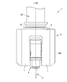
- the machine tool spindle head 1 is a device that is used in a vertical machining center or the like, and that supports a spindle unit 4 on which a tool 2 is mounted and that is driven to rotate.
- the entire machine tool spindle head 1 moves in the XYZ directions of the machine tool, and in addition to the machine tool spindle head 1.
- the supported spindle unit 4 rotates around an axis (A axis) parallel to the XY plane and an axis (C axis) parallel to the Z axis.
- a spindle head 1 for a machine tool includes a spindle 3 to which a tool 2 is attached at the tip, a spindle unit 4 that rotationally drives the spindle, and a first support head (A (Axis driving unit) 6 and a second support head (C axis driving unit) 29 that supports the spindle unit 4 and the first support head 6 so as to be rotatable about the C axis.
- the spindle unit 4 is a built-in motor type in which a spindle motor 5 is incorporated, and the spindle 3 is rotationally driven by the spindle motor 5.
- a tool 2 suitable for cutting is attached to the tip of the spindle 3, and the workpiece to be processed is cut by the rotation of the spindle 3, that is, the tool 2.
- the first support head 6 has a fork-shaped housing 8 as its frame, and a drive motor 14 is disposed in a pair of fork arms 7 that are spaced apart in the direction of the rotation axis (A axis) of the spindle unit 4. It is a double-sided motor type.
- the pair of fork arms 7 has a line-symmetric internal structure with the rotation axis (C axis) of the spindle 3 as a symmetry axis, and each fork arm 7 has a support shaft 9 connected to the spindle unit 4 and A bearing 13 for rotatably supporting the support shaft 9, a DD motor as a drive motor 14 for indexing and driving the spindle unit 4 about the A axis, and a rotary joint 18 for supplying fluid to the spindle unit 4. And a clamping sleeve as clamping means 28 for clamping the support shaft 9 and fixing the spindle unit 4 at a desired indexing angle.
- a rotation detector (encoder) 25 for detecting the rotation angle of the support shaft 9 is provided only in the left fork arm 7 in FIG. All the components other than the rotation detector 25 are line symmetric with respect to the C axis as an axis of symmetry.
- the drive motor 14 directly drives the support shaft 9 without using a drive transmission mechanism such as a gear, and is also called a direct (direct drive) drive motor.
- the drive motor 14 includes a motor rotor 15 and a motor stator 16.
- the motor rotor 15 is fixed to a rotating wheel 10 that constitutes a part of the support shaft 9, and the motor stator 16 is fixed to the fork arm 7.
- the stator sleeve 17 is non-rotatably fitted.
- the rotary joint 18 is for supplying a working fluid to the rotating spindle unit 4 from the side of the first support head 6, distributors 19 and 20 fixed to the fork arm 7, and a support shaft 9. And a shaft 21 that rotates together with the support shaft 9.
- the processing fluid herein include cooling coolant liquid and water, air for removing chips generated during processing, and the like.
- the support shaft 9 is composed of the rotating wheel 10, the shaft 21, and the rotating sleeve 11 described above. Of both ends of the support shaft 9, one end is connected to the spindle unit 4, and the other end is exposed on the outer side surface of the fork arm 7. Further, each of the members of the rotating wheel 10, the shaft 21 and the rotating sleeve 11 is formed with a hole having the same diameter at the center, and these holes support the support shaft 9 in a state where the members are combined. A through hole 12 penetrating in the axial direction is formed. That is, the through hole 12 reaches the spindle unit 4 through the inside of the first support head 6 from the outside of the housing 8 (fork arm 7) of the first support head 6.
- a plurality of wire bodies 22 extending from the spindle unit 4 are routed in the through hole 12.
- the “line body” is a concept including not only electrical cables such as a power line and a signal line but also a fluid supply pipe as defined above.
- FIG. An example in which a line 22a and a signal line 22b are wired is shown. However, some of them are omitted in the drawings.
- the pair of fork arms 7 have a line-symmetric internal structure with the C axis as the axis of symmetry, and the through holes 12 are also formed on both sides of the spindle unit 4.
- the plurality of wire bodies 22 are divided into two groups according to the use, size, etc. of the wire bodies 22 to form two wire body groups, and the respective wire body groups are respectively inserted into the through holes 12 of the pair of support shafts 9.
- the power line 22a and the signal line 22b are separated and wired in the through holes 12 of the separate support shafts 9, respectively.
- each line group is connected to the power line 22a and the signal line 22b. May be mixed).
- the wire 22 routed in the through hole 12 in both the support shafts 9 is an electric cable such as a power line of the spindle motor 5 in the spindle unit 4 and a signal line from the sensor.
- the wire 22 is not limited to these electrical elements, and may include a fluid supply pipe (supply pipe) for supplying the above-described processing fluid. That is, in this example, the processing fluid is supplied from the fluid flow path formed in the housing 8 of the first support head 6 to the spindle unit 4 via the rotary joint 18.
- a part of the machining fluid may be supplied to the spindle unit 4 by a dedicated supply pipe or the like without using a rotary joint, and such a supply pipe and the above-mentioned cables and the like are placed in the through hole 12. It may be something to be routed.
- various one or two or more wire bodies 22 can be divided into two groups according to their uses and sizes.
- the two wire groups can be divided into two groups, and each wire group can be distributed and routed to each of the pair of through holes 12.
- the power line 22a and the signal line 22b are divided into different wire groups, and each is distributed and routed to the through holes 12 of the different support shafts 9, and the electric cable is connected to the wire body 22.
- the electric cables and the fluid supply pipe may be separately arranged. That is, if only electrical cables are wired in the through-hole 12 of one support shaft 9 and only the fluid supply pipe is installed in the through-hole 12 of the other support shaft 9, leakage due to water leakage or short circuit Can be prevented.
- the through-holes 12 are shielded and shielded, such as anti-magnetic, non-conductive, heat-resistant and heat-insulating, according to the type of the wire 22 to be routed, the above effect can be further enhanced.
- a rotary joint 18 is provided in each fork arm 7.
- it is designed as a general solution to maximize the spatial margin in the through hole of the support shaft when inserting cables and the like into the support shaft.
- the diameter of the rotary joint provided so as to surround the support shaft is inevitably increased.
- the distributor of the rotary joint and the shaft rotate relative to each other while the mating surfaces slide, and a seal member is interposed between them, so the sliding resistance is relatively low compared to the case where they are simply in sliding contact. large.
- the sliding resistance between the two is proportional to the area of the sliding surface, and the area is proportional to the diameter of the sliding surface, the sliding resistance increases as the diameter of the rotary joint increases. Therefore, when it is considered to suppress the power loss of the drive motor, it is preferable that the diameter of the rotary joint is small. For this purpose, it is preferable that the diameter of the support shaft is also small.
- the general solution can satisfy the mutually contradictory requirements of increasing the spatial margin in the support shaft and not increasing the diameter (of the sliding surface) of the rotary joint. There wasn't.
- the through hole 12 is formed in any of the pair of support shafts 9 that support the spindle unit 4, and a plurality of cables and the like are distributed and arranged on each support shaft 9,
- the spatial margin in the support shaft 9 can be made larger than that of the prior art without increasing the diameter of the support shaft 9, and the sliding in the rotary joint 18 is ensured while ensuring the spatial margin in the support shaft 9. An increase in sliding resistance of the surface can be avoided.
- the first support head 6 and the second support head 29 are connected by the attachment base portion 23 of the first support head 6.
- the second support head 29 will be described later with reference to FIG. 3, the second support head 29 is held by a machine tool, for example, a machining center or the like.
- the first support head 6 is rotated about an axis parallel to the Z axis of the machining center. Note that the C axis coincides with the central axis of the spindle 3 in the standby state of the spindle 3.
- Cables (power line 22 a and signal line 22 b) as the wire body 22 in the illustrated example pass through the through hole 12 in the support shaft 9 and then the housing 8 and the cover member 24 in the first support head 6.
- the cable insertion hole is inserted into the cable insertion hole 26 formed in the housing 8 from the upper side surface of the housing 8 through the space between them, and is formed around the C axis and opens at the upper part of the first support head 6. 27 and is introduced into the second support head 29.
- the wire 22 passes through a through-hole formed in a rotation shaft that is driven to rotate about the C axis, and is led out to the machine tool 40 side.
- the machine tool 40 is a vertical machining center, and includes a pair of left and right columns 42 provided on a bed 41, a horizontal cross rail 43 that moves in a vertical direction (Z-axis direction) on the pair of columns 42, and a cross A saddle 44 that moves horizontally on the rail 43 in the left-right direction (Y-axis direction), a ram 45 that moves on the saddle 44 in the Z-axis direction, and a bed 41 that moves horizontally in the front-rear direction (X-axis direction).
- Table 46 The spindle head 1 for machine tools according to the present invention is supported by fixing the second support head 29 to the ram 45 in a state where the second support head 29 is inserted into the ram 45.
- FIG. 4 shows another embodiment of the present invention.
- the major difference between this example and the above-described embodiment is that the structure in each fork arm 7 is not symmetrical in this example.
- the spindle head 1 for machine tools is used in a vertical machining center (composite processing machine) or the like as in the first embodiment.
- the spindle head 1 for machine tools of this example is comprised by the spindle unit 4, the 1st support head 6, and the 2nd support head 29 as main components like the above-mentioned Example. .
- the first support head 6 includes support shafts 30 and 31, a drive motor 14, rotary joints 33 and 36, and clamping means 28.
- the structure in each fork arm 7 is not line symmetric with respect to the C axis. That is, in this example, the drive motor 14 for driving is provided only in one fork arm 7, and the clamp sleeve 28 is provided only in the other fork arm 7.
- the rotary joints 33 and 36 are provided in the fork arms 7 and are constituted by distributors 34 and 37 and shafts 35 and 38, respectively.
- the through-hole 12 for routing the wire 22 extended from the spindle unit 4 is formed in a pair of support shafts 30 and 31 similarly to the above-mentioned Example.
- the wire body 22 is routed directly to the through hole 12 formed in the support shaft, whereas in this example, the distributor is provided in the through hole 12 formed in the support shafts 30 and 31.
- 34 and 37 are inserted, and the wire 22 is routed in the through holes 34a and 37a formed in the distributors 34 and 37.
- the wire 22 has a through hole formed in the support shaft 9 as in the example of FIG. 1 due to the difference in structure and arrangement of the drive motor, the support shaft, the rotary joint, and the like in the first support head 6.
- 12 may be routed directly, or may be indirectly routed with other members interposed in the through holes 12 of the support shafts 30 and 31 as in the example of FIG. In the latter case, if the other members are prevented from rotating (for example, the distributors 34 and 37 in the example of FIG. 4 are fixed to the housing 8 of the fork arm 7 and do not rotate), they pass through the inside. Since the wire body 22 and the other member are relatively immovable, it is possible to prevent a trouble that the wire body 22 is rubbed with the other member and disconnected.
- the linear body 22 in the illustrated example passes through the space between the housing 8 and the cover member 24 in the first support head 6 after passing through the through holes 12 (34a, 37a) in the support shafts 30, 31. It is inserted into a cable insertion hole 26 formed in the housing 8 from the upper side surface of the housing 8 and extends from a cable insertion hole 27 formed around the C-axis and opened to the upper part of the first support head. 2 is introduced into the support head 29. In the second support head 29, though not shown, the second support head 29 passes through a through hole formed in a rotary shaft that is driven to rotate about the C axis, and is led out to the machine tool 40 side.
Landscapes
- Engineering & Computer Science (AREA)
- Mechanical Engineering (AREA)
- Machine Tool Units (AREA)
Abstract
Description
2 工具
3 スピンドル
4 スピンドルユニット
5 スピンドルモータ
6 第1の支持ヘッド
7 フォークアーム
8 ハウジング
9 支持軸
10 回動ホイール
11 回動スリーブ
12 貫通孔
13 軸受
14 駆動モータ
15 モータロータ
16 モータステータ
17 ステータスリーブ
18 ロータリジョイント
19 ディストリビュータ
20 ディストリビュータ
21 シャフト
22 線体
22a 動力線
22b 信号線
23 取付基部
24 カバー
25 回転検出器
26 ケーブル挿通用孔
27 ケーブル挿通用孔
28 クランプ手段
29 第2の支持ヘッド
30 支持軸
31 支持軸
33 ロータリジョイント
34 ディストリビュータ
34a 貫通孔
35 シャフト
36 ロータリジョイント
37 ディストリビュータ
37a 貫通孔
38 シャフト
40 工作機械
41 ベッド
42 コラム
43 クロスレール
44 サドル
45 ラム
46 テーブル
Claims (3)
- 先端に工具(2)が取り付けられるスピンドル(3)を内蔵されたスピンドルモータ(5)によって回転駆動するスピンドルユニット(4)と、
前記スピンドルユニット(4)を支持する支持ヘッド(6)であって前記スピンドルユニット(4)の回動軸線(A軸)方向に離間して配置された一対のフォークアーム(7)及び各フォークアーム(7)内において軸受(13)によって回動自在に支持されて前記スピンドルユニット(4)に連結された一対の支持軸(9、30、31)を備えた支持ヘッド(6)と、
を含む工作機械用スピンドルヘッド(1)において、
前記各支持軸(9、30、31)に前記スピンドルユニット(4)から延出される複数本の線体(22)を配索するための貫通孔(12)が形成されており、
前記複数本の線体(22)を2群に分けて2つの線体群にすると共に、各線体群を前記一対の支持軸(9、30、31)の各々に分けて配索する、
ことを特徴とする工作機械用スピンドルヘッド(1)。 - 前記複数の線体(22)が、前記スピンドルモータ(5)に駆動電流を供給するための動力線(22a)と、前記スピンドルユニット(4)内に設けられたセンサからの信号を出力する信号線(22b)とを含み、
前記動力線(22a)と前記信号線(22b)とを異なる前記線体群に分けて配線することを特徴とする請求項1記載の工作機械用スピンドルヘッド(1)。 - 前記各フォークアーム(7)内には、その構成要素として、前記支持軸(9)及び前記軸受(13)に加え、前記支持軸(9)を回動させるための駆動モータ(14)及び前記支持軸(9)の回動位置を保持するためのクランプ手段(28)が配設されており、
前記各構成要素によって構成される前記一対のフォークアーム(7)内の構造が、前記スピンドルユニット(4)における前記スピンドル(3)の回転軸線(C軸)に対し線対称となっていることを特徴とする請求項1または請求項2記載の工作機械用スピンドルヘッド(1)。
Priority Applications (2)
| Application Number | Priority Date | Filing Date | Title |
|---|---|---|---|
| CN200980101221.5A CN101883661B (zh) | 2008-02-08 | 2009-01-26 | 工作机械用主轴接头 |
| US12/865,588 US7938603B2 (en) | 2008-02-08 | 2009-01-26 | Spindle head for machine tool |
Applications Claiming Priority (2)
| Application Number | Priority Date | Filing Date | Title |
|---|---|---|---|
| JP2008-028909 | 2008-02-08 | ||
| JP2008028909A JP5246847B2 (ja) | 2008-02-08 | 2008-02-08 | 工作機械用スピンドルヘッド |
Publications (1)
| Publication Number | Publication Date |
|---|---|
| WO2009098957A1 true WO2009098957A1 (ja) | 2009-08-13 |
Family
ID=40952035
Family Applications (1)
| Application Number | Title | Priority Date | Filing Date |
|---|---|---|---|
| PCT/JP2009/051161 Ceased WO2009098957A1 (ja) | 2008-02-08 | 2009-01-26 | 工作機械用スピンドルヘッド |
Country Status (6)
| Country | Link |
|---|---|
| US (1) | US7938603B2 (ja) |
| JP (1) | JP5246847B2 (ja) |
| KR (1) | KR20100116182A (ja) |
| CN (1) | CN101883661B (ja) |
| TW (1) | TWI429497B (ja) |
| WO (1) | WO2009098957A1 (ja) |
Cited By (5)
| Publication number | Priority date | Publication date | Assignee | Title |
|---|---|---|---|---|
| CN102085616A (zh) * | 2010-12-29 | 2011-06-08 | 中捷机床有限公司 | 卧式五轴加工中心机床用具有大摆角范围的高刚性摆头 |
| CN108723796A (zh) * | 2018-06-29 | 2018-11-02 | 科德数控股份有限公司 | 一种用于五轴复合加工中心的机械单摆头 |
| TWI645932B (zh) * | 2017-03-06 | 2019-01-01 | 豪力輝工業股份有限公司 | 用於工具機之機頭的線材固定裝置 |
| CN113941886A (zh) * | 2020-07-15 | 2022-01-18 | 浙江双正科技股份有限公司 | 一种展刀动力头 |
| JP7159647B2 (ja) | 2018-06-29 | 2022-10-25 | 株式会社ジェイテクト | 旋回主軸装置及び工作機械 |
Families Citing this family (22)
| Publication number | Priority date | Publication date | Assignee | Title |
|---|---|---|---|---|
| JP4996393B2 (ja) * | 2006-09-14 | 2012-08-08 | 津田駒工業株式会社 | 工作機械用の加工用ヘッド |
| DE202007017251U1 (de) * | 2007-12-11 | 2008-02-28 | Deckel Maho Pfronten Gmbh | Bearbeitungseinheit für eine Fräs- und Bohrmaschine |
| CN102216008B (zh) * | 2008-12-02 | 2014-09-17 | 山崎马扎克公司 | 五轴加工双外壳机床的镗孔方法及五轴加工双外壳机床 |
| DE102009020509A1 (de) * | 2009-05-08 | 2010-11-11 | Komet Group Gmbh | Werkzeugmaschine mit Maschinenspindel und Werkzeugaufnahme |
| TWI417155B (zh) * | 2010-07-20 | 2013-12-01 | Ind Tech Res Inst | 齒輪減速式旋轉主軸頭 |
| DE202011108153U1 (de) * | 2011-11-21 | 2012-02-02 | Deckel Maho Pfronten Gmbh | Vorrichtung zum Einsatz in einer Werkzeugmaschine sowie Werkzeugmaschine |
| CN102490026B (zh) * | 2011-12-16 | 2014-04-09 | 江苏新瑞重工科技有限公司 | A、b、c三个数控回转轴于一体的数控铣头 |
| CN102632419B (zh) * | 2012-04-24 | 2014-04-23 | 苏州江源精密机械有限公司 | 双分度数控万能铣头 |
| CN103489046A (zh) * | 2013-09-29 | 2014-01-01 | 中能电力科技开发有限公司 | 风电场短期功率预测方法 |
| CN104690305B (zh) * | 2013-12-03 | 2018-03-16 | 斗山机床株式会社 | 机床用万能主轴箱装置 |
| KR101665316B1 (ko) * | 2014-04-08 | 2016-10-12 | 한국정밀기계(주) | 공작기계용 자동 2축 헤드 장치 |
| DE102015200665A1 (de) * | 2015-01-16 | 2016-07-21 | Deckel Maho Pfronten Gmbh | Bearbeitungseinheit für eine Werkzeugmaschine und eine derartige Werkzeugmaschine |
| JP6622105B2 (ja) * | 2016-02-10 | 2019-12-18 | スピードファム株式会社 | 平面研磨装置 |
| JP6498140B2 (ja) * | 2016-03-15 | 2019-04-10 | 平田機工株式会社 | 作業ユニット及び作業装置 |
| FR3054158B1 (fr) * | 2016-07-21 | 2019-06-28 | Comau France | Machine-outil d’usinage |
| JP6732608B2 (ja) * | 2016-08-31 | 2020-07-29 | 芝浦機械株式会社 | 工作機械 |
| JP6378290B2 (ja) * | 2016-11-11 | 2018-08-22 | ファナック株式会社 | 工作機械 |
| TWI636852B (zh) * | 2017-10-26 | 2018-10-01 | 財團法人工業技術研究院 | 直驅式兩軸加工頭 |
| EP3620259A1 (de) * | 2018-09-07 | 2020-03-11 | Fischer AG Präzisionsspindeln | Spindelkopf für eine werkzeugmaschine und werkzeugmaschine mit einem solchen spindelkopf |
| EP3623104B1 (en) * | 2018-09-12 | 2021-08-11 | FIDIA S.p.A. | C-axis unit for a machine tool with an electrospindle |
| CN113579315B (zh) * | 2021-07-12 | 2022-08-12 | 南通世发船舶机械有限公司 | 一种用于大力钳钳头的铣削设备 |
| CN116572068B (zh) * | 2023-03-24 | 2024-07-23 | 广东科杰技术股份有限公司 | 一种鞋模机床 |
Citations (3)
| Publication number | Priority date | Publication date | Assignee | Title |
|---|---|---|---|---|
| JPS63156632A (ja) * | 1986-12-19 | 1988-06-29 | Okuma Mach Works Ltd | Nc工作機械における工具軸方向加工方式 |
| JP2003048135A (ja) * | 2001-08-07 | 2003-02-18 | Colombo Mauro | 操作ヘッド |
| JP2003170326A (ja) * | 2001-11-30 | 2003-06-17 | Toshiba Mach Co Ltd | 工作機械 |
Family Cites Families (10)
| Publication number | Priority date | Publication date | Assignee | Title |
|---|---|---|---|---|
| JPS63156632U (ja) | 1987-03-31 | 1988-10-14 | ||
| JP2782324B2 (ja) * | 1994-03-29 | 1998-07-30 | オークマ株式会社 | 旋回頭主軸ハウジングの締め・緩め検出機構 |
| US5584621A (en) * | 1995-06-13 | 1996-12-17 | Bertsche Engineering Corp. | Direct drive multiple axes rotary spindle head for milling machine |
| CN2644060Y (zh) * | 2003-08-27 | 2004-09-29 | 江苏多棱数控机床股份有限公司 | 五轴联动龙门数控铣床 |
| JP2006289595A (ja) * | 2005-04-14 | 2006-10-26 | Nsk Ltd | スピンドル装置 |
| US7293340B1 (en) * | 2006-12-15 | 2007-11-13 | Roundtop Machinery Industries Co., Ltd | Direct drive spindle, machining center and methods of fabricating the same |
| JP5281744B2 (ja) * | 2006-12-27 | 2013-09-04 | 津田駒工業株式会社 | 主軸装置及びそれを備えた複合加工工作機械 |
| US7891920B2 (en) * | 2006-12-27 | 2011-02-22 | Nsk Ltd. | Spindle device and machining center including the same |
| US8641338B2 (en) * | 2006-12-27 | 2014-02-04 | Nsk Ltd. | Spindle device, machining center including the spindle device, and method for assembling the spindle device |
| DE202007017251U1 (de) * | 2007-12-11 | 2008-02-28 | Deckel Maho Pfronten Gmbh | Bearbeitungseinheit für eine Fräs- und Bohrmaschine |
-
2008
- 2008-02-08 JP JP2008028909A patent/JP5246847B2/ja not_active Expired - Fee Related
- 2008-12-22 TW TW097149996A patent/TWI429497B/zh not_active IP Right Cessation
-
2009
- 2009-01-26 US US12/865,588 patent/US7938603B2/en not_active Expired - Fee Related
- 2009-01-26 CN CN200980101221.5A patent/CN101883661B/zh not_active Expired - Fee Related
- 2009-01-26 WO PCT/JP2009/051161 patent/WO2009098957A1/ja not_active Ceased
- 2009-01-26 KR KR1020107017304A patent/KR20100116182A/ko not_active Abandoned
Patent Citations (3)
| Publication number | Priority date | Publication date | Assignee | Title |
|---|---|---|---|---|
| JPS63156632A (ja) * | 1986-12-19 | 1988-06-29 | Okuma Mach Works Ltd | Nc工作機械における工具軸方向加工方式 |
| JP2003048135A (ja) * | 2001-08-07 | 2003-02-18 | Colombo Mauro | 操作ヘッド |
| JP2003170326A (ja) * | 2001-11-30 | 2003-06-17 | Toshiba Mach Co Ltd | 工作機械 |
Cited By (6)
| Publication number | Priority date | Publication date | Assignee | Title |
|---|---|---|---|---|
| CN102085616A (zh) * | 2010-12-29 | 2011-06-08 | 中捷机床有限公司 | 卧式五轴加工中心机床用具有大摆角范围的高刚性摆头 |
| TWI645932B (zh) * | 2017-03-06 | 2019-01-01 | 豪力輝工業股份有限公司 | 用於工具機之機頭的線材固定裝置 |
| CN108723796A (zh) * | 2018-06-29 | 2018-11-02 | 科德数控股份有限公司 | 一种用于五轴复合加工中心的机械单摆头 |
| JP7159647B2 (ja) | 2018-06-29 | 2022-10-25 | 株式会社ジェイテクト | 旋回主軸装置及び工作機械 |
| CN108723796B (zh) * | 2018-06-29 | 2023-12-12 | 科德数控股份有限公司 | 一种用于五轴复合加工中心的机械单摆头 |
| CN113941886A (zh) * | 2020-07-15 | 2022-01-18 | 浙江双正科技股份有限公司 | 一种展刀动力头 |
Also Published As
| Publication number | Publication date |
|---|---|
| JP5246847B2 (ja) | 2013-07-24 |
| TWI429497B (zh) | 2014-03-11 |
| JP2009184089A (ja) | 2009-08-20 |
| CN101883661B (zh) | 2012-06-27 |
| US7938603B2 (en) | 2011-05-10 |
| KR20100116182A (ko) | 2010-10-29 |
| CN101883661A (zh) | 2010-11-10 |
| US20100322734A1 (en) | 2010-12-23 |
| TW200934610A (en) | 2009-08-16 |
Similar Documents
| Publication | Publication Date | Title |
|---|---|---|
| JP5246847B2 (ja) | 工作機械用スピンドルヘッド | |
| EP2204258B1 (en) | Machine tool spindle head | |
| JP5057843B2 (ja) | 工作機械用の角度割出し装置 | |
| JP2006297561A (ja) | 複合旋盤 | |
| CN101687291B (zh) | 工作机械用分度装置 | |
| JPWO2008050747A1 (ja) | 工作機械用の角度割出し装置 | |
| JP2010000590A (ja) | 工作機械用の割出し装置における発熱体の冷却回路 | |
| JP5057845B2 (ja) | 工作機械用の角度割出し装置 | |
| CN101913088B (zh) | 机床用的加工用头 | |
| CN101486152A (zh) | 工作机械用的转动分度装置 | |
| CN110167701B (zh) | 5轴加工中心 | |
| JP6463297B2 (ja) | 工作機械の主軸装置 | |
| JP5368192B2 (ja) | 旋回型回転工具ヘッドのケーブル接続構造 | |
| JP2012045648A (ja) | 旋回テーブル装置および工作機械 | |
| JP3630370B2 (ja) | インデックス装置 | |
| JP2012047220A (ja) | 流路接続装置および流路接続方法 | |
| JP2020040204A (ja) | 高速切削を伴う工作機械のためのc軸ユニット | |
| CN222903240U (zh) | 一种利用活齿减速器和力矩电机组合的ac摇篮转台 | |
| CN117564306A (zh) | 主轴头和五轴龙门加工中心 | |
| JP5138213B2 (ja) | 主軸装置及びそれを備えた複合加工工作機械 | |
| JP2008161953A (ja) | 主軸装置及びそれを備えた複合加工工作機械 | |
| CN117885229A (zh) | 一种外转子电主轴 | |
| WO2024070227A1 (ja) | 駆動装置 | |
| JPH0276603A (ja) | 工作機械の主軸台構造 | |
| JPH04275803A (ja) | 工作機械のスピンドル台装置 |
Legal Events
| Date | Code | Title | Description |
|---|---|---|---|
| WWE | Wipo information: entry into national phase |
Ref document number: 200980101221.5 Country of ref document: CN |
|
| 121 | Ep: the epo has been informed by wipo that ep was designated in this application |
Ref document number: 09707542 Country of ref document: EP Kind code of ref document: A1 |
|
| WWE | Wipo information: entry into national phase |
Ref document number: 12865588 Country of ref document: US |
|
| ENP | Entry into the national phase |
Ref document number: 20107017304 Country of ref document: KR Kind code of ref document: A |
|
| NENP | Non-entry into the national phase |
Ref country code: DE |
|
| 122 | Ep: pct application non-entry in european phase |
Ref document number: 09707542 Country of ref document: EP Kind code of ref document: A1 |