WO2009093604A1 - 有機ナノチューブ製造方法および製造装置 - Google Patents
有機ナノチューブ製造方法および製造装置 Download PDFInfo
- Publication number
- WO2009093604A1 WO2009093604A1 PCT/JP2009/050863 JP2009050863W WO2009093604A1 WO 2009093604 A1 WO2009093604 A1 WO 2009093604A1 JP 2009050863 W JP2009050863 W JP 2009050863W WO 2009093604 A1 WO2009093604 A1 WO 2009093604A1
- Authority
- WO
- WIPO (PCT)
- Prior art keywords
- organic
- organic nanotube
- dispersion solution
- raw material
- nanotube
- Prior art date
- Legal status (The legal status is an assumption and is not a legal conclusion. Google has not performed a legal analysis and makes no representation as to the accuracy of the status listed.)
- Ceased
Links
Images
Classifications
-
- B—PERFORMING OPERATIONS; TRANSPORTING
- B82—NANOTECHNOLOGY
- B82Y—SPECIFIC USES OR APPLICATIONS OF NANOSTRUCTURES; MEASUREMENT OR ANALYSIS OF NANOSTRUCTURES; MANUFACTURE OR TREATMENT OF NANOSTRUCTURES
- B82Y40/00—Manufacture or treatment of nanostructures
-
- A—HUMAN NECESSITIES
- A61—MEDICAL OR VETERINARY SCIENCE; HYGIENE
- A61P—SPECIFIC THERAPEUTIC ACTIVITY OF CHEMICAL COMPOUNDS OR MEDICINAL PREPARATIONS
- A61P43/00—Drugs for specific purposes, not provided for in groups A61P1/00-A61P41/00
-
- B—PERFORMING OPERATIONS; TRANSPORTING
- B01—PHYSICAL OR CHEMICAL PROCESSES OR APPARATUS IN GENERAL
- B01J—CHEMICAL OR PHYSICAL PROCESSES, e.g. CATALYSIS OR COLLOID CHEMISTRY; THEIR RELEVANT APPARATUS
- B01J2/00—Processes or devices for granulating materials, e.g. fertilisers in general; Rendering particulate materials free flowing in general, e.g. making them hydrophobic
- B01J2/02—Processes or devices for granulating materials, e.g. fertilisers in general; Rendering particulate materials free flowing in general, e.g. making them hydrophobic by dividing the liquid material into drops, e.g. by spraying, and solidifying the drops
- B01J2/04—Processes or devices for granulating materials, e.g. fertilisers in general; Rendering particulate materials free flowing in general, e.g. making them hydrophobic by dividing the liquid material into drops, e.g. by spraying, and solidifying the drops in a gaseous medium
-
- B—PERFORMING OPERATIONS; TRANSPORTING
- B82—NANOTECHNOLOGY
- B82Y—SPECIFIC USES OR APPLICATIONS OF NANOSTRUCTURES; MEASUREMENT OR ANALYSIS OF NANOSTRUCTURES; MANUFACTURE OR TREATMENT OF NANOSTRUCTURES
- B82Y30/00—Nanotechnology for materials or surface science, e.g. nanocomposites
-
- C—CHEMISTRY; METALLURGY
- C01—INORGANIC CHEMISTRY
- C01B—NON-METALLIC ELEMENTS; COMPOUNDS THEREOF; METALLOIDS OR COMPOUNDS THEREOF NOT COVERED BY SUBCLASS C01C
- C01B32/00—Carbon; Compounds thereof
- C01B32/15—Nano-sized carbon materials
-
- F—MECHANICAL ENGINEERING; LIGHTING; HEATING; WEAPONS; BLASTING
- F26—DRYING
- F26B—DRYING SOLID MATERIALS OR OBJECTS BY REMOVING LIQUID THEREFROM
- F26B3/00—Drying solid materials or objects by processes involving the application of heat
- F26B3/02—Drying solid materials or objects by processes involving the application of heat by convection, i.e. heat being conveyed from a heat source to the materials or objects to be dried by a gas or vapour, e.g. air
- F26B3/10—Drying solid materials or objects by processes involving the application of heat by convection, i.e. heat being conveyed from a heat source to the materials or objects to be dried by a gas or vapour, e.g. air the gas or vapour carrying the materials or objects to be dried with it
- F26B3/12—Drying solid materials or objects by processes involving the application of heat by convection, i.e. heat being conveyed from a heat source to the materials or objects to be dried by a gas or vapour, e.g. air the gas or vapour carrying the materials or objects to be dried with it in the form of a spray, i.e. sprayed or dispersed emulsions or suspensions
Definitions
- the present invention relates to a method and an apparatus for easily and mass-manufacturing high-performance materials, for example, organic nanotubes useful as inclusion / separation materials or drug sustained-release materials in the field of pharmaceuticals and chemical products.
- nanotube-like materials having pores of 0.5 to 500 nm carbon nanotubes, which are inorganic nanotubes synthesized for the first time artificially, are expected to have properties derived from their size, shape, chemical structure, etc.
- Patent Document 1 In addition to the development of applications for nanoscale electronic devices, high-strength materials, electron emission, gas storage, etc., research on mass production has been vigorously pursued from the demand for practical application (Patent Document 1).
- cyclodextrin is known as an organic cyclic compound having pores of 1 nm or less, and various low-molecular organic compounds can be encapsulated in the annular hollow portion, so that the health food field, cosmetic field, antibacterial deodorant and household goods
- Various cyclodextrin inclusion products have been researched and commercialized for the purpose of contributing to the fields, industry, agriculture, and environment (Patent Document 2, etc.). Cyclodextrin can be mass-produced, and its structure is a structure in which 6 to 8 units of glucose are linked in a ring shape, and safety for the living body is ensured. Therefore, a wide range of applications has been developed.
- the present inventors have already developed organic nanotubes obtained by self-assembly in an aqueous solution (Patent Document 3, Non-Patent Documents 1 to 3, etc.).
- the organic nanotube developed by the present inventors has a hollow cylinder portion with an inner pore size of 5 to 500 nm and an order of magnitude larger than cyclodextrin, and therefore has a diameter of 5 to 500 nm that cannot be included in cyclodextrin.
- functional substances such as proteins, viruses, drugs, and metal fine particles can be trapped inside the hollow cylinder, and development of their use is expected.
- An object of this invention is to provide the method and apparatus which can manufacture an organic nanotube continuously by pressurizing the organic nanotube raw material dispersion solution which consists of an organic nanotube raw material and an organic solvent, and letting it pass through a fine orifice.
- Another object of the present invention is to provide an apparatus that can continuously produce organic nanotubes by using a spray dryer as a drying means and has high drying efficiency.
- the organic nanotube production method of the present invention applies an organic nanotube raw material dispersion solution composed of an organic nanotube raw material and an organic solvent, presses the orifice through the orifice, and a shearing force acts when passing through the orifice. Then, an oversaturated solution in which the organic nanotube raw material is completely dissolved in an organic solvent is produced, and the oversaturated solution is cooled to form an organic nanotube dispersion solution. Further, the organic nanotube production method of the present invention is characterized in that the organic nanotube is recovered as a dry powder by spraying the organic nanotube dispersion solution from a spray nozzle of a spray dryer apparatus and separating it into solvent vapor and organic nanotube. Yes.
- the organic nanotube production apparatus of the present invention includes a tank that contains an organic nanotube raw material dispersion solution composed of an organic nanotube raw material and an organic solvent, and a pump that pressurizes and pumps the organic nanotube raw material dispersion solution from the tank, A cylindrical casing for continuously flowing the organic nanotube raw material dispersion solution pumped from the pump and an orifice mounted in the cylindrical casing are provided, and an organic nanotube deposition tube is connected to the outlet of the cylindrical casing. And a cooling means for cooling the organic nanotube deposition tube to deposit organic nanotubes.
- the organic nanotube production apparatus of the present invention connects the organic nanotube precipitation tube to a spray nozzle of a spray dryer apparatus, and the spray dryer apparatus performs drying for spray drying the organic nanotube dispersion solution sprayed from the spray nozzle.
- a drying air supply means for supplying dry air around the spray nozzle and a pressure air supply means for supplying pressure air to the spray nozzle are provided.
- the organic nanotube production apparatus of the present invention is provided with a cyclone connected to the drying chamber of the spray dryer device via a transfer pipe, a product container provided at the lower part of the cyclone, and connected to the upper part of the cyclone.
- the exhaust pipe is connected to an exhaust fan via a heat exchanger provided around the organic nanotube deposition pipe, and the exhaust fan is connected to a solvent recovery container.
- the organic nanotube production apparatus of the present invention is provided with a mesh connected to a drying chamber of the spray dryer apparatus via a transport pipe, and an exhaust pipe provided around the mesh is provided around the organic nanotube deposition pipe. It connects to an exhaust fan via the heat exchanger provided in this, and this exhaust fan is connected to a solvent collection
- the organic nanotube production method of the present invention has the following excellent effects. (1) By adopting a means for pressurizing the organic nanotube raw material dispersion solution and passing it through the orifice, it is possible to continuously synthesize and produce organic nanotubes. In addition, the amount of solvent required can be greatly reduced to 1/5 to 1/10 compared to the production method in the atmosphere. (2) By using a spray dryer apparatus, the solvent strongly held in the narrow inner space of the organic nanotube can be easily removed. In addition, since it can be dried in a short time, structural changes due to heat can be prevented.
- the organic nanotube production apparatus of the present invention has the following excellent effects.
- a pump for pressurizing and feeding the organic nanotube raw material dispersion solution at high pressure and pressure is provided, and a cylindrical casing for continuously flowing the organic nanotube raw material dispersion solution fed from the pump is installed in the cylindrical casing.
- a pump for pressurizing and feeding the organic nanotube raw material dispersion solution at high pressure and pressure is provided, and a cylindrical casing for continuously flowing the organic nanotube raw material dispersion solution fed from the pump is installed in the cylindrical casing.
- the organic nanotube deposition tube provided at the outlet of the cylindrical casing is connected to the spray dryer device, the cyclone is connected to the drying chamber of the spray dryer device, the product container is provided at the lower part of the cyclone, and the cyclone is provided.
- An exhaust pipe connected to the upper part is connected to an exhaust fan via a heat exchanger provided around the organic nanotube deposition pipe, and the exhaust fan is connected to a solvent recovery container, thereby Equipment that pressurizes and cools, recovers solvent, and simplifies high energy consumption operation and reduces energy costs It can be realized. In addition, it can implement
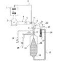
- FIG. 1 is an overall view for explaining an embodiment of an organic nanotube production method and apparatus according to the present invention.
- the organic nanotube raw material When the organic nanotube raw material is dispersed in methanol and passed through the orifice in the cylindrical casing, a high-pressure shearing force is applied with an increase in the temperature of the solution, so that the organic nanotube raw material instantly dissolves to form an oversaturated solution.
- the pressure applied when passing through the orifice should be as high as possible, and is a maximum of 245 MPa in a general apparatus.
- the organic nanotube raw material is self-assembled in the supersaturated solution by cooling as quickly as possible with a heat exchanger, and an organic nanotube dispersion solution can be produced.
- the organic nanotube dispersion solution is passed through a spray dryer apparatus.
- the solvent can be evaporated without destroying the structure of the organic nanotube by spraying the organic nanotube dispersion liquid from the spray nozzle together with the dry air heated to the gel-liquid crystal transition temperature or lower of the organic nanotube raw material. Thereafter, by continuously introducing the cyclone into a cyclone, the solvent vapor and the organic nanotube can be separated to produce a dry powdered organic nanotube.
- the organic nanotube dispersion solution may be an organic nanotube dispersion solution produced by another method.
- FIG. 1 is an overall view for explaining an embodiment of an organic nanotube production method and apparatus according to the present invention.
- the organic nanotube production apparatus is provided with a tank 1, and a predetermined amount of organic nanotube raw material and organic solvent are accommodated in the tank 1.
- a raw material of the organic nanotube N-glycoside type glycolipid or peptide lipid is used.
- N-glycoside type glycolipid is represented by the following general formula (1) G-NHCO-R 1 (1) Wherein G represents a sugar residue excluding the hemiacetal hydroxyl group bonded to the anomeric carbon atom of the sugar, and R 1 represents an unsaturated hydrocarbon group having 10 to 39 carbon atoms. is there.
- the peptide lipid is a peptide lipid having a long-chain hydrocarbon group, that is, the following general formula (2) R 2 CO (NH—CHR 3 —CO) m OH (2) Or the following general formula (3) H (NH—CHR 3 Y—CO) m NHR 2 (3) (Wherein R 2 represents a hydrocarbon group having 6 to 18 carbon atoms, R 3 represents an amino acid side chain, and m represents 1 to 10).
- the solvent is characterized in that an organic solvent is used. This organic solvent is heated below the boiling point. Therefore, the amount of N-glycoside glycolipid or peptide lipid dissolved can be increased.
- the concentration of N-glycoside glycolipid or peptide lipid in this solution is preferably as high as possible, and most preferably saturated.
- the organic solvent alcohols having a boiling point of 120 ° C. or lower or cyclic ethers having a boiling point of 120 ° C. or lower can be used. This organic solvent may be used alone or in combination of two or more. Moreover, you may mix a small amount of water with this organic solvent.
- the organic nanotube raw material is partially dissolved in an organic solvent and partially dispersed to prepare a dispersion solution.
- a cylindrical casing 3 for continuously flowing the organic nanotube raw material dispersion solution discharged from the pump 2 so as to be connected to the suction side of the pump 2 and connected to the discharge side of the pump 2 is provided in the tank 1. Is provided.
- a fine orifice 5 for restricting the flow of the organic nanotube raw material dispersion is provided in the cylindrical casing 3. The orifice 5 is provided in only one stage in the figure, but may be provided in two or more stages.
- An organic nanotube deposition tube 6 is connected to the outlet side of the cylindrical casing 3, and the organic nanotube deposition tube 6 is connected to a spray nozzle 11 of a spray dryer device 10 as a drying means.
- a return pipe 8 that connects the organic nanotube deposition pipe 6 and the tank 1 is connected to the organic nanotube deposition pipe 6 in the middle, and a switching valve 7 is provided at the connection portion. For this reason, when an organic nanotube does not precipitate for some reason, the switching valve 7 can be operated to return the organic nanotube dispersion solution to the tank 1.
- the organic nanotube raw material dispersion solution discharged from the pump 2 passes through the orifice 5
- a high-pressure shear force is applied as the temperature of the solution increases, so that the organic nanotube raw material is completely dissolved in an organic solvent in a normal container.
- a predetermined time and a solvent amount are required.
- the organic nanotube raw material is instantly completely dissolved in 1/5 to 1/10 volume of solvent, and the organic nanotube precipitation tube 6 becomes an oversaturated solution.
- the organic nanotube raw material self-assembles to precipitate the organic nanotube 4.
- the spray dryer apparatus 10 includes a drying chamber 12 for spray-drying the dispersion liquid containing the organic nanotubes 4 from the spray nozzle 11 described above, and drying is performed by supplying dry air around the spray nozzle 11 at the top of the drying chamber 12.
- An air supply unit 14 is connected, and a heater 15 is provided in the middle of the dry air supply unit 14. Further, a pressure air supply means 16 for supplying pressure air to the spray nozzle 11 is connected to the spray nozzle 11.
- a lower chamber 13 is provided below the drying chamber 12 of the spray dryer apparatus 10, and the lower chamber 13 is connected to a cyclone 18 by a transport pipe 17.
- the dispersion liquid containing the organic nanotubes 4 sprayed from the spray nozzle 11 droplets are instantly evaporated in the drying chamber 12, and dried organic nanotubes are formed. Both the evaporated gas and the dried organic nanotube enter the cyclone 18 through the transfer tube 17 from the lower chamber 13.
- a product container 19 is provided at the lower part of the cyclone 18, and an exhaust pipe 20 is connected to the upper part of the cyclone 18.
- the exhaust pipe 20 is connected to an exhaust fan 22 provided at the end portion via a heat exchanger 21 for cooling the organic nanotube deposition pipe 6 described above.
- the temperature in the heat exchanger 21 is about ⁇ 20 ° C. to 20 ° C.
- the mixture of the organic solvent vapor and the organic nanotube is centrifuged by the cyclone 18, the organic nanotube is accumulated in the product container 19, and the solvent vapor is heat exchanged by the heat exchanger 21, and then the solvent not shown from the exhaust fan 22. Sent to the collector.
- the solvent liquefied in the solvent recovery device is filled in the tank 1 and used again for the production of organic nanotubes.
- a filter may be installed in front of the exhaust fan 22 in order to collect ultrafine powder that could not be collected by the cyclone 18.
- the apparatus for separating the mixture of the organic solvent vapor and the organic nanotube is not limited to the cyclone, and a mesh-like bag filter or the like can also be used.
- the filter is surrounded by a large cylindrical container so that the vapor of the organic solvent can be sent to the heat exchanger 21.
- Peptide lipids of general formula (2) which are organic nanotube raw materials (wherein R 2 is 13 hydrocarbon groups, R 3 is hydrogen, m is 2) 25 g are dispersed in 1 L of methanol, pressure 245 MPa, flow rate 300 ml / min. After passing through the orifice, a methanol dispersion of organic nanotubes was produced by rapidly cooling with a heat exchanger in which cold water was flowed at 5 degrees.
- Peptide lipid of general formula (2) which is a raw material of organic nanotubes (wherein R 2 is 13 hydrocarbon groups, R 3 is hydrogen, m is 2) 50 g is dispersed in 1 L of methanol, and this dispersion is After heating, the solution was passed through the orifice at a pressure of 245 MPa and a flow rate of 300 ml / min, and then rapidly cooled by a heat exchanger in which cold water was flowed at 5 degrees to produce a methanol dispersion of organic nanotubes.
Landscapes
- Chemical & Material Sciences (AREA)
- Engineering & Computer Science (AREA)
- Nanotechnology (AREA)
- Organic Chemistry (AREA)
- Condensed Matter Physics & Semiconductors (AREA)
- General Physics & Mathematics (AREA)
- Physics & Mathematics (AREA)
- Crystallography & Structural Chemistry (AREA)
- Materials Engineering (AREA)
- Chemical Kinetics & Catalysis (AREA)
- Life Sciences & Earth Sciences (AREA)
- Inorganic Chemistry (AREA)
- Manufacturing & Machinery (AREA)
- Health & Medical Sciences (AREA)
- Composite Materials (AREA)
- Microbiology (AREA)
- Mechanical Engineering (AREA)
- General Engineering & Computer Science (AREA)
- Nuclear Medicine, Radiotherapy & Molecular Imaging (AREA)
- Veterinary Medicine (AREA)
- Public Health (AREA)
- General Health & Medical Sciences (AREA)
- Animal Behavior & Ethology (AREA)
- Pharmacology & Pharmacy (AREA)
- Medicinal Chemistry (AREA)
- General Chemical & Material Sciences (AREA)
- Bioinformatics & Cheminformatics (AREA)
- Carbon And Carbon Compounds (AREA)
- Medicinal Preparation (AREA)
- Saccharide Compounds (AREA)
Abstract
本発明は、有機ナノチューブ原料および有機溶媒からなる有機ナノチューブ原料分散溶液を加圧して微細なオリフィスを通過させることにより、連続して有機ナノチューブを製造できる方法および装置を提供することを目的とする。
本発明の有機ナノチューブの製造装置は、有機ナノチューブ原料および有機溶媒からなる有機ナノチューブ原料分散溶液を収容するタンクおよび該タンクから有機ナノチューブ原料分散溶液を加圧して高圧・圧送するポンプを設け、該ポンプから圧送された有機ナノチューブ原料分散溶液を連続して流すための筒状ケーシングと該筒状ケーシング内に装着されたオリフィスとを設け、筒状ケーシングの出口に有機ナノチューブ析出管を連結して設け、該有機ナノチューブ析出管に続いて乾燥手段を設けることを特徴としている。
Description
本発明は、高機能性材料、例えば、医薬・化成品分野における包接・分離用材料又は薬剤徐放材料として有用な有機ナノチューブを簡便かつ大量に製造する方法および装置に関する。
0.5~500nmの細孔を有するナノチューブ状材料のなかで、人工的に初めて合成された無機系ナノチューブであるカーボンナノチューブは、そのサイズ、形状、化学構造、等に由来する特性への期待から、ナノスケールの電子デバイス、高強度材料、電子放出、及びガス貯蔵等への用途開発とともに、実用化への要望から精力的に量産化に関する研究が進められている(特許文献1)。
また、1nm以下の細孔を有する有機環状化合物としてシクロデキストリンが知られており、種々の低分子有機化合物をその環状中空部に内包できることから、健康食品分野、化粧品分野、抗菌消臭・家庭品分野、工業・農業・環境分野への貢献を目的に、様々なシクロデキストリン包接品が研究開発され、事業化されている(特許文献2等)。シクロデキストリンは、量産可能であり、その構造がブドウ糖6~8単位を環状に連ねたものであり、生体への安全性が確保されていることから、広範な用途開発がなされている。
また、1nm以下の細孔を有する有機環状化合物としてシクロデキストリンが知られており、種々の低分子有機化合物をその環状中空部に内包できることから、健康食品分野、化粧品分野、抗菌消臭・家庭品分野、工業・農業・環境分野への貢献を目的に、様々なシクロデキストリン包接品が研究開発され、事業化されている(特許文献2等)。シクロデキストリンは、量産可能であり、その構造がブドウ糖6~8単位を環状に連ねたものであり、生体への安全性が確保されていることから、広範な用途開発がなされている。
一方、本発明者らは、既に水溶液中で自己集合して得られる有機ナノチューブを開発している(特許文献3、非特許文献1~3等)。本発明者らが開発したこの有機ナノチューブは中空シリンダー部の内孔サイズが5~500nmであり、シクロデキストリンよりも一桁以上大きいため、シクロデキストリンでは包接することができない5~500nmの径を有するタンパク質、ウイルス、薬剤、金属微粒子などの機能性物質をその中空シリンダー内部に捕捉できる可能性があり、その用途開発が期待されている。
しかし、今までこの有機ナノチューブは水溶液中で合成されてきたため、その製造には水を大量に必要とする上に、加熱撹拌操作と長時間の放置を必要としていたため、量産化が困難であった。また、この有機ナノチューブは、水溶液中で合成されるため、その構造中に強固に水を保持しており(以下、この方法で合成した有機ナノチューブを「含水有機ナノチューブ」という。)、通常の方法ではその水を除くことが困難であり、含水有機ナノチューブ内へ機能性物質の包接を効率良く行うことができないという問題があった。
特表2003-535794号公報
特開2005-306763号公報
特許第3664401号公報
Langmuir, 2005, 21,743
Chem.Comm., 2004, 500
Chem.Mater., 2004, 16, 2826
本発明者らは、上記問題を解決するため研究を進めた結果、N-グリコシド型糖脂質又はペプチド脂質を水ではなく有機溶媒中で自己集合させることによって、無水有機ナノチューブを簡便かつ大量に製造できることを見出し、すでに有機ナノチューブおよびその製造方法について特許出願している(PCT/JP2007/061703、PCT/JP2007/061706)。
また、これまで、有機ナノチューブの製造装置について試行錯誤を繰り返し検討してきたところ、原料を有機溶媒に溶解させる手段としては、ポンプで圧送した懸濁溶液を微細なオリフィスを通すことにより、高圧剪断力が加えられ、溶質を短時間に完全溶解する装置が適していることが判明した。更に、この装置を利用することで、有機ナノチューブの製造に必要な溶媒量を、前記特許(PCT/JP2007/061703、PCT/JP2007/061706)記載の大気中での製造方法に比べて1/5~1/10と大幅に減らすことが出来る。
また、得られたエマルジョンをろ過乾燥しなくてはならないが、このエマルジョンは有機ナノチューブの超濃厚分散液であることから、ろ過乾燥に時間がかかること、また、エマルジョン中でナノチューブ以外の構造に変化してしまう危険性があることから、連続的に効率良く乾燥できる手段が必要である。ろ過乾燥手段について検討を重ねた結果、スプレードライヤーという装置が適していることが判明した。このスプレードライヤーとは、ノズルから溶液を噴霧し連続して乾燥する装置である。
また、これまで、有機ナノチューブの製造装置について試行錯誤を繰り返し検討してきたところ、原料を有機溶媒に溶解させる手段としては、ポンプで圧送した懸濁溶液を微細なオリフィスを通すことにより、高圧剪断力が加えられ、溶質を短時間に完全溶解する装置が適していることが判明した。更に、この装置を利用することで、有機ナノチューブの製造に必要な溶媒量を、前記特許(PCT/JP2007/061703、PCT/JP2007/061706)記載の大気中での製造方法に比べて1/5~1/10と大幅に減らすことが出来る。
また、得られたエマルジョンをろ過乾燥しなくてはならないが、このエマルジョンは有機ナノチューブの超濃厚分散液であることから、ろ過乾燥に時間がかかること、また、エマルジョン中でナノチューブ以外の構造に変化してしまう危険性があることから、連続的に効率良く乾燥できる手段が必要である。ろ過乾燥手段について検討を重ねた結果、スプレードライヤーという装置が適していることが判明した。このスプレードライヤーとは、ノズルから溶液を噴霧し連続して乾燥する装置である。
本発明は、有機ナノチューブ原料および有機溶媒からなる有機ナノチューブ原料分散溶液を加圧して微細なオリフィスを通過させることにより、連続して有機ナノチューブを製造できる方法および装置を提供することを目的とする。
また、本発明は、乾燥手段としてスプレードライヤーを利用することにより、連続して有機ナノチューブを製造できるとともに乾燥効率のよい装置を提供することを目的とする。
また、本発明は、乾燥手段としてスプレードライヤーを利用することにより、連続して有機ナノチューブを製造できるとともに乾燥効率のよい装置を提供することを目的とする。
上記目的を達成するため、本発明の有機ナノチューブの製造方法は、有機ナノチューブ原料および有機溶媒からなる有機ナノチューブ原料分散溶液を加圧してオリフィスを通過させ、該オリフィスを通過する際に剪断力が作用して有機溶媒に有機ナノチューブ原料が完全溶解した超過飽和溶液を生成し、超過飽和溶液を冷却することにより有機ナノチューブ分散溶液を形成することを特徴としている。
また、本発明の有機ナノチューブの製造方法は、有機ナノチューブ分散溶液をスプレードライヤー装置の噴霧ノズルから噴霧して溶媒蒸気と有機ナノチューブに分離することにより、有機ナノチューブを乾燥粉末として回収することを特徴としている。
また、本発明の有機ナノチューブの製造装置は、有機ナノチューブ原料および有機溶媒からなる有機ナノチューブ原料分散溶液を収容するタンクおよび該タンクから有機ナノチューブ原料分散溶液を加圧して高圧・圧送するポンプを設け、該ポンプから圧送された有機ナノチューブ原料分散溶液を連続して流すための筒状ケーシングと該筒状ケーシング内に装着されたオリフィスとを設け、筒状ケーシングの出口に有機ナノチューブ析出管を連結して設け、該有機ナノチューブ析出管を冷却して有機ナノチューブを析出させる冷却手段を設けることを特徴としている。
また、本発明の有機ナノチューブの製造装置は、前記有機ナノチューブ析出管をスプレードライヤー装置の噴霧ノズルに連結し、スプレードライヤー装置は、噴霧ノズルから噴霧される有機ナノチューブ分散溶液を噴霧乾燥するための乾燥チャンバーを備え、噴霧ノズルの周囲に乾燥空気を供給する乾燥空気供給手段、および、噴霧ノズルに圧力空気を供給するための圧力空気供給手段を設けることを特徴としている。
また、本発明の有機ナノチューブの製造装置は、前記スプレードライヤー装置の乾燥チャンバーに搬送管を介して接続されたサイクロンを設け、該サイクロンの下部に生成物容器を設け、サイクロン上部に接続して設けられた排気管を前記有機ナノチューブ析出管の周囲に設けられた熱交換器を経由して排気ファンに接続し、該排気ファンを溶媒回収容器に接続することを特徴としている。
また、本発明の有機ナノチューブの製造装置は、前記スプレードライヤー装置の乾燥チャンバーに搬送管を介して接続されたメッシュを設け、該メッシュの周囲に設けられた排気管を前記有機ナノチューブ析出管の周囲に設けられた熱交換器を経由して排気ファンに接続し、該排気ファンを溶媒回収容器に接続することを特徴としている。
また、本発明の有機ナノチューブの製造方法は、有機ナノチューブ分散溶液をスプレードライヤー装置の噴霧ノズルから噴霧して溶媒蒸気と有機ナノチューブに分離することにより、有機ナノチューブを乾燥粉末として回収することを特徴としている。
また、本発明の有機ナノチューブの製造装置は、有機ナノチューブ原料および有機溶媒からなる有機ナノチューブ原料分散溶液を収容するタンクおよび該タンクから有機ナノチューブ原料分散溶液を加圧して高圧・圧送するポンプを設け、該ポンプから圧送された有機ナノチューブ原料分散溶液を連続して流すための筒状ケーシングと該筒状ケーシング内に装着されたオリフィスとを設け、筒状ケーシングの出口に有機ナノチューブ析出管を連結して設け、該有機ナノチューブ析出管を冷却して有機ナノチューブを析出させる冷却手段を設けることを特徴としている。
また、本発明の有機ナノチューブの製造装置は、前記有機ナノチューブ析出管をスプレードライヤー装置の噴霧ノズルに連結し、スプレードライヤー装置は、噴霧ノズルから噴霧される有機ナノチューブ分散溶液を噴霧乾燥するための乾燥チャンバーを備え、噴霧ノズルの周囲に乾燥空気を供給する乾燥空気供給手段、および、噴霧ノズルに圧力空気を供給するための圧力空気供給手段を設けることを特徴としている。
また、本発明の有機ナノチューブの製造装置は、前記スプレードライヤー装置の乾燥チャンバーに搬送管を介して接続されたサイクロンを設け、該サイクロンの下部に生成物容器を設け、サイクロン上部に接続して設けられた排気管を前記有機ナノチューブ析出管の周囲に設けられた熱交換器を経由して排気ファンに接続し、該排気ファンを溶媒回収容器に接続することを特徴としている。
また、本発明の有機ナノチューブの製造装置は、前記スプレードライヤー装置の乾燥チャンバーに搬送管を介して接続されたメッシュを設け、該メッシュの周囲に設けられた排気管を前記有機ナノチューブ析出管の周囲に設けられた熱交換器を経由して排気ファンに接続し、該排気ファンを溶媒回収容器に接続することを特徴としている。
本発明の有機ナノチューブ製造方法は、以下のような優れた効果を奏する。
(1)有機ナノチューブ原料分散溶液を加圧してオリフィスを通過させる手段を採用することにより、連続して有機ナノチューブを合成し製造することができる。また、必要な溶媒量も大気中での製造方法に比べて1/5~1/10と大幅に減らすことが出来る。
(2)スプレードライヤー装置を使用することにより、有機ナノチューブの狭い内空間に強力に保持された溶媒を容易に除去することが出来る。また、短時間で乾燥が可能であるため、熱による構造変化も防ぐことが出来る。
また、本発明の有機ナノチューブ製造装置は、以下のような優れた効果を奏する。
(1)有機ナノチューブ原料分散溶液を加圧して高圧・圧送するポンプを設け、該ポンプから圧送された有機ナノチューブ原料分散溶液を連続して流すための筒状ケーシングと該筒状ケーシング内に装着されたオリフィスとを設け、筒状ケーシングの出口に設けた有機ナノチューブ析出管とスプレードライヤー装置を連結することにより、連続して有機ナノチューブを製造できるとともに乾燥効率のよい装置を提供することができる。
(2)有機ナノチューブ原料分散溶液を加圧して高圧・圧送するポンプを設け、該ポンプから圧送された有機ナノチューブ原料分散溶液を連続して流すための筒状ケーシングと該筒状ケーシング内に装着されたオリフィスとを設け、筒状ケーシングの出口に設けた有機ナノチューブ析出管をスプレードライヤー装置に連結し、スプレードライヤー装置の乾燥チャンバーにサイクロンを接続し、該サイクロンの下部に生成物容器を設け、サイクロン上部に接続して設けられた排気管を前記有機ナノチューブ析出管の周囲に設けられた熱交換器を経由して排気ファンに接続し、該排気ファンを溶媒回収容器に接続することにより、溶液の加圧および冷却、溶媒の回収という煩雑、高エネルギー消費操作を簡便でエネルギーコスト削減に繋がる装置で実現することができる。なお、サイクロンに代えてメッシュを用いても同様に実現することができる。
(1)有機ナノチューブ原料分散溶液を加圧してオリフィスを通過させる手段を採用することにより、連続して有機ナノチューブを合成し製造することができる。また、必要な溶媒量も大気中での製造方法に比べて1/5~1/10と大幅に減らすことが出来る。
(2)スプレードライヤー装置を使用することにより、有機ナノチューブの狭い内空間に強力に保持された溶媒を容易に除去することが出来る。また、短時間で乾燥が可能であるため、熱による構造変化も防ぐことが出来る。
また、本発明の有機ナノチューブ製造装置は、以下のような優れた効果を奏する。
(1)有機ナノチューブ原料分散溶液を加圧して高圧・圧送するポンプを設け、該ポンプから圧送された有機ナノチューブ原料分散溶液を連続して流すための筒状ケーシングと該筒状ケーシング内に装着されたオリフィスとを設け、筒状ケーシングの出口に設けた有機ナノチューブ析出管とスプレードライヤー装置を連結することにより、連続して有機ナノチューブを製造できるとともに乾燥効率のよい装置を提供することができる。
(2)有機ナノチューブ原料分散溶液を加圧して高圧・圧送するポンプを設け、該ポンプから圧送された有機ナノチューブ原料分散溶液を連続して流すための筒状ケーシングと該筒状ケーシング内に装着されたオリフィスとを設け、筒状ケーシングの出口に設けた有機ナノチューブ析出管をスプレードライヤー装置に連結し、スプレードライヤー装置の乾燥チャンバーにサイクロンを接続し、該サイクロンの下部に生成物容器を設け、サイクロン上部に接続して設けられた排気管を前記有機ナノチューブ析出管の周囲に設けられた熱交換器を経由して排気ファンに接続し、該排気ファンを溶媒回収容器に接続することにより、溶液の加圧および冷却、溶媒の回収という煩雑、高エネルギー消費操作を簡便でエネルギーコスト削減に繋がる装置で実現することができる。なお、サイクロンに代えてメッシュを用いても同様に実現することができる。
1 タンク
2 ポンプ
3 筒状ケーシング
4 有機ナノチューブ
5 オリフィス
6 有機ナノチューブ析出管
7 切替弁
8 戻り管
10 スプレードライヤー装置
11 噴霧ノズル
12 乾燥チャンバー
13 下部チャンバー
14 乾燥空気供給手段
15 加熱ヒータ
16 圧力空気供給手段
17 搬送管
18 サイクロン
19 生成物容器
20 排気管20
21 熱交換器21
22 排気ファン22
2 ポンプ
3 筒状ケーシング
4 有機ナノチューブ
5 オリフィス
6 有機ナノチューブ析出管
7 切替弁
8 戻り管
10 スプレードライヤー装置
11 噴霧ノズル
12 乾燥チャンバー
13 下部チャンバー
14 乾燥空気供給手段
15 加熱ヒータ
16 圧力空気供給手段
17 搬送管
18 サイクロン
19 生成物容器
20 排気管20
21 熱交換器21
22 排気ファン22
有機ナノチューブ原料をメタノールに分散し、筒状ケーシング内のオリフィスを通過させると、溶液の温度上昇を伴い高圧剪断力が加えられるため、有機ナノチューブ原料が瞬時に溶解し超過飽和溶液ができる。オリフィスを通過させる際にかかる圧力はできるだけ高い方が良く、一般的な装置では最高245MPaである。オリフィスを通過後、熱交換機によりできるだけ急速に冷却することで、超過飽和溶液中で有機ナノチューブ原料が自己集合し有機ナノチューブ分散溶液を製造できる。
次に、有機ナノチューブ分散溶液をスプレードライヤー装置に通す。有機ナノチューブ原料のゲル-液晶転移温度以下に加熱された乾燥空気と共に有機ナノチューブ分散液を噴霧ノズルから噴霧することで、有機ナノチューブの構造を壊すことなく溶媒を蒸発させることができる。その後、連続してサイクロンに導入することで、溶媒蒸気と有機ナノチューブを分離し、乾燥粉末状の有機ナノチューブを製造することが出来る。なお、有機ナノチューブ分散溶液は他の方法によって製造された有機ナノチューブ分散溶液であってもよい。
以下、図面を参照して、本発明の有機ナノチューブ製造の実施の形態について詳細に説明するが、本発明は、これに限定されて解釈されるものではなく、本発明の範囲を逸脱しない限りにおいて、当業者の知識に基づいて、種々の変更、修正、改良を加えうるものである。
次に、有機ナノチューブ分散溶液をスプレードライヤー装置に通す。有機ナノチューブ原料のゲル-液晶転移温度以下に加熱された乾燥空気と共に有機ナノチューブ分散液を噴霧ノズルから噴霧することで、有機ナノチューブの構造を壊すことなく溶媒を蒸発させることができる。その後、連続してサイクロンに導入することで、溶媒蒸気と有機ナノチューブを分離し、乾燥粉末状の有機ナノチューブを製造することが出来る。なお、有機ナノチューブ分散溶液は他の方法によって製造された有機ナノチューブ分散溶液であってもよい。
以下、図面を参照して、本発明の有機ナノチューブ製造の実施の形態について詳細に説明するが、本発明は、これに限定されて解釈されるものではなく、本発明の範囲を逸脱しない限りにおいて、当業者の知識に基づいて、種々の変更、修正、改良を加えうるものである。
図1は、本発明の有機ナノチューブ製造方法および装置の実施の形態を説明するための全体図である。
有機ナノチューブ製造装置には、タンク1が設けられ、該タンク1内に有機ナノチューブの原料および有機溶媒が所定量収容されている。
有機ナノチューブの原料としては、N-グリコシド型糖脂質又はペプチド脂質が用いられる。
N-グリコシド型糖脂質は、下記一般式(1)
G-NHCO-R1 (1)
(式中、Gは糖のアノマー炭素原子に結合するヘミアセタール水酸基を除いた糖残基を表し、R1は炭素数が10~39の不飽和炭化水素基を表す。)で表わされるものである。
また、ペプチド脂質は、長鎖炭化水素基を有するペプチド脂質、すなわち下記の一般式(2)
R2CO(NH-CHR3-CO)mOH (2)
又は下記の一般式(3)
H(NH-CHR3Y-CO)mNHR2 (3)
(式中、R2は炭素数6~18の炭化水素基、R3はアミノ酸側鎖、mは1~10を表す。)で表わされるものである。
有機ナノチューブ製造装置には、タンク1が設けられ、該タンク1内に有機ナノチューブの原料および有機溶媒が所定量収容されている。
有機ナノチューブの原料としては、N-グリコシド型糖脂質又はペプチド脂質が用いられる。
N-グリコシド型糖脂質は、下記一般式(1)
G-NHCO-R1 (1)
(式中、Gは糖のアノマー炭素原子に結合するヘミアセタール水酸基を除いた糖残基を表し、R1は炭素数が10~39の不飽和炭化水素基を表す。)で表わされるものである。
また、ペプチド脂質は、長鎖炭化水素基を有するペプチド脂質、すなわち下記の一般式(2)
R2CO(NH-CHR3-CO)mOH (2)
又は下記の一般式(3)
H(NH-CHR3Y-CO)mNHR2 (3)
(式中、R2は炭素数6~18の炭化水素基、R3はアミノ酸側鎖、mは1~10を表す。)で表わされるものである。
溶媒としては、有機溶媒を用いる点に特徴がある。この有機溶媒は沸点以下に加温する。そのためN-グリコシド型糖脂質又はペプチド脂質の溶解量を多くすることができる。この溶液中のN-グリコシド型糖脂質又はペプチド脂質の濃度は高いほど好ましく、飽和であることが最も好ましい。
この有機溶媒としては、沸点が120℃以下であるアルコール類又は沸点が120℃以下である環状エーテル類を用いることができる。この有機溶媒は単独でもよいし、2種以上の混合溶媒であってもよい。また、この有機溶媒に少量の水を混合してもよい。
この有機溶媒としては、沸点が120℃以下であるアルコール類又は沸点が120℃以下である環状エーテル類を用いることができる。この有機溶媒は単独でもよいし、2種以上の混合溶媒であってもよい。また、この有機溶媒に少量の水を混合してもよい。
タンク1内において、有機ナノチューブ原料は有機溶媒に一部溶解され、また一部分散され、分散溶液として調製されている。
タンク1にポンプ2の吸入側が接続して設けられ、該ポンプ2の吐出側に接続するようにして、ポンプ2から吐出された有機ナノチューブ原料分散溶液を連続して流すための筒状ケーシング3が設けられている。該筒状ケーシング3内には有機ナノチューブ原料分散溶液の流れを絞るための微細なオリフィス5が設けられている。このオリフィス5は、図では1段のみ設けられているが、2段以上、複数段設けてもよい。ポンプ2から吐出された有機ナノチューブ原料分散溶液は微細なオリフィス5を通過する際、狭まった壁面との間で高圧剪断力が加えられ、溶質を個々の分子が孤立した状態に分散する(完全溶解)。オリフィス5を通過する際の圧力は約100MPa~300MPaである。
タンク1にポンプ2の吸入側が接続して設けられ、該ポンプ2の吐出側に接続するようにして、ポンプ2から吐出された有機ナノチューブ原料分散溶液を連続して流すための筒状ケーシング3が設けられている。該筒状ケーシング3内には有機ナノチューブ原料分散溶液の流れを絞るための微細なオリフィス5が設けられている。このオリフィス5は、図では1段のみ設けられているが、2段以上、複数段設けてもよい。ポンプ2から吐出された有機ナノチューブ原料分散溶液は微細なオリフィス5を通過する際、狭まった壁面との間で高圧剪断力が加えられ、溶質を個々の分子が孤立した状態に分散する(完全溶解)。オリフィス5を通過する際の圧力は約100MPa~300MPaである。
筒状ケーシング3の出口側には有機ナノチューブ析出管6が接続され、該有機ナノチューブ析出管6は乾燥手段としてのスプレードライヤー装置10の噴霧ノズル11に連結されている。また、有機ナノチューブ析出管6の途中には有機ナノチューブ析出管6と前記タンク1を連結する戻り管8が接続されており、該接続部には切替弁7が設けられている。このため、万一、何らかの原因で有機ナノチューブが析出されないときには、切替弁7を操作して有機ナノチューブ分散溶液をタンク1に戻すことができる。
ポンプ2から吐出された有機ナノチューブ原料分散溶液が、オリフィス5を通過する際に、溶液の温度上昇を伴い高圧剪断力が加えられるため、通常の容器中で有機溶媒に有機ナノチューブ原料を完全溶解するためには所定の時間と溶媒量を要するところ、瞬時に1/5~1/10容量の溶媒に有機ナノチューブ原料が完全溶解され、前記有機ナノチューブ析出管6においては超過飽和溶液となる。この有機ナノチューブ析出管6における超過飽和溶液が後記する熱交換器21によって冷却される過程において、有機ナノチューブ原料が自己集合することにより有機ナノチューブ4を析出する。
スプレードライヤー装置10は、前記した噴霧ノズル11から有機ナノチューブ4を含む分散液を噴霧乾燥するための乾燥チャンバー12を備え、該乾燥チャンバー12頂部には噴霧ノズル11の周囲に乾燥空気を供給する乾燥空気供給手段14が接続され、該乾燥空気供給手段14の途中に加熱ヒータ15が設けられている。
また、噴霧ノズル11に圧力空気を供給するための圧力空気供給手段16が噴霧ノズル11に接続されている。
また、噴霧ノズル11に圧力空気を供給するための圧力空気供給手段16が噴霧ノズル11に接続されている。
スプレードライヤー装置10の乾燥チャンバー12の下部には下部チャンバー13が設けられ、該下部チャンバー13は搬送管17によりサイクロン18に接続されている。
噴霧ノズル11から噴霧される有機ナノチューブ4を含む分散液は、乾燥チャンバー12において瞬時に液滴が蒸発され、乾燥状態の有機ナノチューブが形成される。蒸発した気体と乾燥状態の有機ナノチューブは共に下部チャンバー13から搬送管17を通りサイクロン18に入る。
噴霧ノズル11から噴霧される有機ナノチューブ4を含む分散液は、乾燥チャンバー12において瞬時に液滴が蒸発され、乾燥状態の有機ナノチューブが形成される。蒸発した気体と乾燥状態の有機ナノチューブは共に下部チャンバー13から搬送管17を通りサイクロン18に入る。
サイクロン18の下部には生成物容器19が設けられ、また、サイクロン18の上部には排気管20が接続されている。排気管20は、前記した有機ナノチューブ析出管6を冷却するための熱交換器21を経由して終端部に設けられた排気ファン22に接続している。熱交換器21での温度は、-20℃~20℃くらいである。
有機溶媒の蒸気と有機ナノチューブの混合物はサイクロン18で遠心分離され、有機ナノチューブは生成物容器19に集積され、溶媒蒸気は熱交換器21で熱交換を行った後、排気ファン22から図示しない溶媒回収器に送られる。溶媒回収器で液状になった溶媒は前記したタンク1に充填され、再び有機ナノチューブ製造に利用される。この時、サイクロン18で集めきれなかった極微細粉末を回収するため、排気ファン22の手前にフィルターを設置してもよい。
また、有機溶媒の蒸気と有機ナノチューブの混合物を分離する装置としては、サイクロンには限らず、メッシュ状の例えばバグフィルターなどを用いることもできる。この場合、フィルターの周囲を一回り大きな筒状の容器で囲い、有機溶媒の蒸気を熱交換機21へ送ることができるようにする。
(製造例1)
有機ナノチューブ原料である一般式(2)のペプチド脂質(式中、R2は13の炭化水素基、R3は水素、mは2)25gをメタノール1Lに分散し、圧力245MPa、流速300ml/分でオリフィスを通過させた後、5度の冷水を流した熱交換機で急速に冷却させることで、有機ナノチューブのメタノール分散液を製造した。
有機ナノチューブ原料である一般式(2)のペプチド脂質(式中、R2は13の炭化水素基、R3は水素、mは2)25gをメタノール1Lに分散し、圧力245MPa、流速300ml/分でオリフィスを通過させた後、5度の冷水を流した熱交換機で急速に冷却させることで、有機ナノチューブのメタノール分散液を製造した。
(製造例2)
有機ナノチューブ原料である一般式(2)のペプチド脂質(式中、R2は13の炭化水素基、R3は水素、mは2)50gをメタノール1Lに分散し、この分散液を50度に加温した後、圧力245MPa、流速300ml/分でオリフィスを通過させた後、5度の冷水を流した熱交換機で急速に冷却させることで、有機ナノチューブのメタノール分散液を製造した。
有機ナノチューブ原料である一般式(2)のペプチド脂質(式中、R2は13の炭化水素基、R3は水素、mは2)50gをメタノール1Lに分散し、この分散液を50度に加温した後、圧力245MPa、流速300ml/分でオリフィスを通過させた後、5度の冷水を流した熱交換機で急速に冷却させることで、有機ナノチューブのメタノール分散液を製造した。
(製造例3)
有機ナノチューブ原料である一般式(2)のペプチド脂質(式中、R2は13の炭化水素基、R3は水素、mは2)20gをメタノール1Lに分散し、この分散液を50度に加温した後、圧力245MPa、流速100ml/分でオリフィスを通過させた直後に、20度の水を流した熱交換機で急速に冷却させることで、有機ナノチューブのメタノール分散液を製造した。
有機ナノチューブ原料である一般式(2)のペプチド脂質(式中、R2は13の炭化水素基、R3は水素、mは2)20gをメタノール1Lに分散し、この分散液を50度に加温した後、圧力245MPa、流速100ml/分でオリフィスを通過させた直後に、20度の水を流した熱交換機で急速に冷却させることで、有機ナノチューブのメタノール分散液を製造した。
(製造例4)
製造例3で製造した有機ナノチューブ分散液170mlを、加熱ヒータで60度に熱した圧力空気により噴霧ノズルから吐出させ、その後サイクロンで回収することにより、1.9gの乾燥粉末の有機ナノチューブを得た。
製造例3で製造した有機ナノチューブ分散液170mlを、加熱ヒータで60度に熱した圧力空気により噴霧ノズルから吐出させ、その後サイクロンで回収することにより、1.9gの乾燥粉末の有機ナノチューブを得た。
(製造例5)
製造例3で製造した有機ナノチューブ分散液200mlを、加熱ヒータで60度に熱した圧力空気により噴霧ノズルから吐出させ、その後バグフィルターで回収することにより、2.6gの乾燥粉末の有機ナノチューブを得た。
製造例3で製造した有機ナノチューブ分散液200mlを、加熱ヒータで60度に熱した圧力空気により噴霧ノズルから吐出させ、その後バグフィルターで回収することにより、2.6gの乾燥粉末の有機ナノチューブを得た。
Claims (6)
- 有機ナノチューブ原料および有機溶媒からなる有機ナノチューブ原料分散溶液を加圧してオリフィスを通過させ、該オリフィスを通過する際に剪断力が作用して有機溶媒に有機ナノチューブ原料が完全溶解した超過飽和溶液を生成し、超過飽和溶液を冷却することにより有機ナノチューブを析出させて有機ナノチューブ分散溶液を形成することを特徴とする有機ナノチューブの製造方法。
- 有機ナノチューブ分散溶液をスプレードライヤー装置の噴霧ノズルから噴霧して溶媒蒸気と有機ナノチューブに分離することにより、有機ナノチューブを乾燥粉末として回収することを特徴とする有機ナノチューブの製造方法。
- 有機ナノチューブ原料および有機溶媒からなる有機ナノチューブ原料分散溶液を収容するタンクおよび該タンクから有機ナノチューブ原料分散溶液を加圧して高圧・圧送するポンプを設け、該ポンプから圧送された有機ナノチューブ原料分散溶液を連続して流すための筒状ケーシングと該筒状ケーシング内に装着されたオリフィスとを設け、筒状ケーシングの出口に有機ナノチューブ析出管を連結して設け、該有機ナノチューブ析出管を冷却して有機ナノチューブを析出させる冷却手段を設けたこと特徴とする有機ナノチューブの製造装置。
- 前記有機ナノチューブ析出管をスプレードライヤー装置の噴霧ノズルに連結し、スプレードライヤー装置は、噴霧ノズルから噴霧される有機ナノチューブ分散溶液を噴霧乾燥するための乾燥チャンバーを備え、噴霧ノズルの周囲に乾燥空気を供給する乾燥空気供給手段、および、噴霧ノズルに圧力空気を供給するための圧力空気供給手段を設けることを特徴とする請求項3記載の有機ナノチューブの製造装置。
- 前記スプレードライヤー装置の乾燥チャンバーに搬送管を介して接続されたサイクロンを設け、該サイクロンの下部に生成物容器を設け、サイクロン上部に接続して設けられた排気管を前記有機ナノチューブ析出管の周囲に設けられた熱交換器を経由して排気ファンに接続し、該排気ファンを溶媒回収容器に接続することを特徴とする請求項4記載の有機ナノチューブの製造装置。
- 前記スプレードライヤー装置の乾燥チャンバーに搬送管を介して接続されたメッシュを設け、該メッシュの周囲に設けられた排気管を前記有機ナノチューブ析出管の周囲に設けられた熱交換器を経由して排気ファンに接続し、該排気ファンを溶媒回収容器に接続することを特徴とする請求項4記載の有機ナノチューブの製造装置。
Priority Applications (2)
| Application Number | Priority Date | Filing Date | Title |
|---|---|---|---|
| JP2009550531A JP5408619B2 (ja) | 2008-01-24 | 2009-01-21 | 有機ナノチューブ製造方法および製造装置 |
| US12/863,434 US20110052702A1 (en) | 2008-01-24 | 2009-01-21 | Method and Apparatus for Producing Organic Nanotubes |
Applications Claiming Priority (2)
| Application Number | Priority Date | Filing Date | Title |
|---|---|---|---|
| JP2008-013280 | 2008-01-24 | ||
| JP2008013280 | 2008-01-24 |
Publications (1)
| Publication Number | Publication Date |
|---|---|
| WO2009093604A1 true WO2009093604A1 (ja) | 2009-07-30 |
Family
ID=40901112
Family Applications (1)
| Application Number | Title | Priority Date | Filing Date |
|---|---|---|---|
| PCT/JP2009/050863 Ceased WO2009093604A1 (ja) | 2008-01-24 | 2009-01-21 | 有機ナノチューブ製造方法および製造装置 |
Country Status (3)
| Country | Link |
|---|---|
| US (1) | US20110052702A1 (ja) |
| JP (1) | JP5408619B2 (ja) |
| WO (1) | WO2009093604A1 (ja) |
Cited By (2)
| Publication number | Priority date | Publication date | Assignee | Title |
|---|---|---|---|---|
| JP2012213747A (ja) * | 2011-04-01 | 2012-11-08 | Powrex Corp | 微粒子製造装置及び微粒子製造方法 |
| CN112097560A (zh) * | 2020-09-23 | 2020-12-18 | 常州奕诺隆机械科技有限公司 | 一种用于石油化工的换热设备 |
Families Citing this family (2)
| Publication number | Priority date | Publication date | Assignee | Title |
|---|---|---|---|---|
| US8920614B2 (en) * | 2012-12-18 | 2014-12-30 | Chung-Shan Institute Of Science And Technology | Device designed for continuous production of graphene flakes by electrochemical method |
| KR102047370B1 (ko) * | 2016-07-14 | 2019-11-22 | 주식회사 엘지화학 | 카본나노튜브 제품 건조 및 회수 장치 및 이를 이용한 카본나노튜브 제조방법 |
Citations (4)
| Publication number | Priority date | Publication date | Assignee | Title |
|---|---|---|---|---|
| JPH0687120A (ja) * | 1990-08-23 | 1994-03-29 | Gebr Sulzer Ag | 静的層流ミキサー装置 |
| JP2002034510A (ja) * | 2000-07-21 | 2002-02-05 | Takehara Kagaku Kogyo Kk | 炭酸カルシウム粉体組成物とその製造方法及びこれを用いたエマルジョンの製造方法 |
| JP2004077731A (ja) * | 2002-08-15 | 2004-03-11 | Fuji Photo Film Co Ltd | 写真処理廃液の処理システム |
| WO2007145158A1 (ja) * | 2006-06-14 | 2007-12-21 | National Institute Of Advanced Industrial Science And Technology | 中空繊維状有機ナノチューブ及びその製造方法 |
Family Cites Families (4)
| Publication number | Priority date | Publication date | Assignee | Title |
|---|---|---|---|---|
| JP2662413B2 (ja) * | 1988-04-12 | 1997-10-15 | 昭和電工株式会社 | 気相成長炭素繊維の製造方法 |
| US6919064B2 (en) * | 2000-06-02 | 2005-07-19 | The Board Of Regents Of The University Of Oklahoma | Process and apparatus for producing single-walled carbon nanotubes |
| US6413487B1 (en) * | 2000-06-02 | 2002-07-02 | The Board Of Regents Of The University Of Oklahoma | Method and apparatus for producing carbon nanotubes |
| JP3664401B2 (ja) * | 2003-01-22 | 2005-06-29 | 独立行政法人科学技術振興機構 | N−グリコシド型糖脂質及びこれから成る中空繊維状有機ナノチューブ |
-
2009
- 2009-01-21 WO PCT/JP2009/050863 patent/WO2009093604A1/ja not_active Ceased
- 2009-01-21 US US12/863,434 patent/US20110052702A1/en not_active Abandoned
- 2009-01-21 JP JP2009550531A patent/JP5408619B2/ja not_active Expired - Fee Related
Patent Citations (4)
| Publication number | Priority date | Publication date | Assignee | Title |
|---|---|---|---|---|
| JPH0687120A (ja) * | 1990-08-23 | 1994-03-29 | Gebr Sulzer Ag | 静的層流ミキサー装置 |
| JP2002034510A (ja) * | 2000-07-21 | 2002-02-05 | Takehara Kagaku Kogyo Kk | 炭酸カルシウム粉体組成物とその製造方法及びこれを用いたエマルジョンの製造方法 |
| JP2004077731A (ja) * | 2002-08-15 | 2004-03-11 | Fuji Photo Film Co Ltd | 写真処理廃液の処理システム |
| WO2007145158A1 (ja) * | 2006-06-14 | 2007-12-21 | National Institute Of Advanced Industrial Science And Technology | 中空繊維状有機ナノチューブ及びその製造方法 |
Non-Patent Citations (1)
| Title |
|---|
| MASUMI ASAKAWA ET AL.: "Yasukute Anzen · Ko Kino na Yuki Nano Tube", EXPECTED MATERIALS FOR THE FUTURE, vol. 7, no. 10, 10 October 2007 (2007-10-10), pages 38 - 43 * |
Cited By (2)
| Publication number | Priority date | Publication date | Assignee | Title |
|---|---|---|---|---|
| JP2012213747A (ja) * | 2011-04-01 | 2012-11-08 | Powrex Corp | 微粒子製造装置及び微粒子製造方法 |
| CN112097560A (zh) * | 2020-09-23 | 2020-12-18 | 常州奕诺隆机械科技有限公司 | 一种用于石油化工的换热设备 |
Also Published As
| Publication number | Publication date |
|---|---|
| US20110052702A1 (en) | 2011-03-03 |
| JP5408619B2 (ja) | 2014-02-05 |
| JPWO2009093604A1 (ja) | 2011-05-26 |
Similar Documents
| Publication | Publication Date | Title |
|---|---|---|
| Esfandiari | Production of micro and nano particles of pharmaceutical by supercritical carbon dioxide | |
| JP5183068B2 (ja) | 大気噴出凍結乾燥法による粉末形成 | |
| JP5408619B2 (ja) | 有機ナノチューブ製造方法および製造装置 | |
| Kröber et al. | Materials processing with supercritical antisolvent precipitation: process parameters and morphology of tartaric acid | |
| KR101387007B1 (ko) | 그래핀의 제조방법 | |
| JP2004511530A (ja) | ホスト分子に包接された活性成分からなる微細粒子の製造方法 | |
| EA028302B1 (ru) | Устройство и способ для изготовления дисперсий и твёрдых фаз | |
| EP2033934B1 (en) | Hollow-fiber-like organic nanotube and process for production thereof | |
| Deshpande et al. | Supercritical fluid technology: concepts and pharmaceutical applications | |
| Baiker et al. | Supercritical fluids; opportunities in heterogeneous catalysis | |
| JP2020108890A (ja) | フラッシュ蒸発によって共結晶を製造するための方法 | |
| US6821429B2 (en) | Method and device for capturing fine particles by trapping in a solid mixture of carbon dioxide snow type | |
| Zuev et al. | Preparation of Polyurethane–Carbon Nanotube Composites via Suspension Supercritical Antisolvent Precipitation | |
| CN100396277C (zh) | 使用超临界流体制备活性物质与多孔载体的相互作用复合物的方法 | |
| CN104248950A (zh) | 一种钯/碳纳米管催化剂及制备和应用 | |
| JP7481259B2 (ja) | スプレー溶液の連続調整を伴うスプレードライプロセス | |
| JP2021514954A5 (ja) | ||
| CN103808117B (zh) | 一种介孔粉体材料连续干燥装置及其方法 | |
| JP5142021B2 (ja) | 独立分散金属微粒子及び独立分散金属微粒子分散媒体の製造方法と製造装置と独立分散金属微粒子及び独立分散金属微粒子分散媒体 | |
| Abdelhamid | Ionic liquids for nanomaterials recycling | |
| JP5256451B2 (ja) | カーボンナノチューブ分散液およびその製造方法、並びにその利用 | |
| RU2356609C1 (ru) | Способ получения нано- и микрочастиц водорастворимых веществ с использованием сверхкритического диоксида углерода | |
| JP2012213747A (ja) | 微粒子製造装置及び微粒子製造方法 | |
| CN101948136B (zh) | 一种高分散片状偏钨酸铵的制备方法 | |
| Gomes et al. | Micronization and encapsulation: application of supercritical fluids in water removal |
Legal Events
| Date | Code | Title | Description |
|---|---|---|---|
| 121 | Ep: the epo has been informed by wipo that ep was designated in this application |
Ref document number: 09703891 Country of ref document: EP Kind code of ref document: A1 |
|
| WWE | Wipo information: entry into national phase |
Ref document number: 2009550531 Country of ref document: JP |
|
| NENP | Non-entry into the national phase |
Ref country code: DE |
|
| 122 | Ep: pct application non-entry in european phase |
Ref document number: 09703891 Country of ref document: EP Kind code of ref document: A1 |