WO2009093469A1 - Compresseur à vis - Google Patents
Compresseur à vis Download PDFInfo
- Publication number
- WO2009093469A1 WO2009093469A1 PCT/JP2009/000266 JP2009000266W WO2009093469A1 WO 2009093469 A1 WO2009093469 A1 WO 2009093469A1 JP 2009000266 W JP2009000266 W JP 2009000266W WO 2009093469 A1 WO2009093469 A1 WO 2009093469A1
- Authority
- WO
- WIPO (PCT)
- Prior art keywords
- spiral groove
- rotor
- oil
- screw
- screw rotor
- Prior art date
Links
Images


Classifications
-
- F—MECHANICAL ENGINEERING; LIGHTING; HEATING; WEAPONS; BLASTING
- F04—POSITIVE - DISPLACEMENT MACHINES FOR LIQUIDS; PUMPS FOR LIQUIDS OR ELASTIC FLUIDS
- F04C—ROTARY-PISTON, OR OSCILLATING-PISTON, POSITIVE-DISPLACEMENT MACHINES FOR LIQUIDS; ROTARY-PISTON, OR OSCILLATING-PISTON, POSITIVE-DISPLACEMENT PUMPS
- F04C29/00—Component parts, details or accessories of pumps or pumping installations, not provided for in groups F04C18/00 - F04C28/00
- F04C29/04—Heating; Cooling; Heat insulation
- F04C29/042—Heating; Cooling; Heat insulation by injecting a fluid
-
- F—MECHANICAL ENGINEERING; LIGHTING; HEATING; WEAPONS; BLASTING
- F04—POSITIVE - DISPLACEMENT MACHINES FOR LIQUIDS; PUMPS FOR LIQUIDS OR ELASTIC FLUIDS
- F04C—ROTARY-PISTON, OR OSCILLATING-PISTON, POSITIVE-DISPLACEMENT MACHINES FOR LIQUIDS; ROTARY-PISTON, OR OSCILLATING-PISTON, POSITIVE-DISPLACEMENT PUMPS
- F04C18/00—Rotary-piston pumps specially adapted for elastic fluids
- F04C18/48—Rotary-piston pumps with non-parallel axes of movement of co-operating members
- F04C18/50—Rotary-piston pumps with non-parallel axes of movement of co-operating members the axes being arranged at an angle of 90 degrees
- F04C18/52—Rotary-piston pumps with non-parallel axes of movement of co-operating members the axes being arranged at an angle of 90 degrees of intermeshing engagement type, i.e. with engagement of co-operating members similar to that of toothed gearing
-
- F—MECHANICAL ENGINEERING; LIGHTING; HEATING; WEAPONS; BLASTING
- F04—POSITIVE - DISPLACEMENT MACHINES FOR LIQUIDS; PUMPS FOR LIQUIDS OR ELASTIC FLUIDS
- F04C—ROTARY-PISTON, OR OSCILLATING-PISTON, POSITIVE-DISPLACEMENT MACHINES FOR LIQUIDS; ROTARY-PISTON, OR OSCILLATING-PISTON, POSITIVE-DISPLACEMENT PUMPS
- F04C18/00—Rotary-piston pumps specially adapted for elastic fluids
- F04C18/08—Rotary-piston pumps specially adapted for elastic fluids of intermeshing-engagement type, i.e. with engagement of co-operating members similar to that of toothed gearing
- F04C18/12—Rotary-piston pumps specially adapted for elastic fluids of intermeshing-engagement type, i.e. with engagement of co-operating members similar to that of toothed gearing of other than internal-axis type
- F04C18/14—Rotary-piston pumps specially adapted for elastic fluids of intermeshing-engagement type, i.e. with engagement of co-operating members similar to that of toothed gearing of other than internal-axis type with toothed rotary pistons
- F04C18/16—Rotary-piston pumps specially adapted for elastic fluids of intermeshing-engagement type, i.e. with engagement of co-operating members similar to that of toothed gearing of other than internal-axis type with toothed rotary pistons with helical teeth, e.g. chevron-shaped, screw type
Definitions
- the present invention relates to a screw compressor in which oil or refrigerant is injected into a compression chamber.
- a compressor for compressing refrigerant or air a single screw compressor including one screw rotor, a casing for housing the screw rotor, and two gate rotors is known (see Patent Document 1).
- a compression chamber is formed by the gate of the gate rotor meshing with the spiral groove of the screw rotor, and the refrigerant in the compression chamber is compressed by the rotation of the screw rotor and the gate rotor.
- oil is injected into the compression chamber in order to lubricate the spiral groove and the gate and to improve the sealing performance of the gap between the spiral groove and the gate.
- oil or refrigerant hereinafter also referred to as oil or the like
- the injected oil or the like may become a resistance of the rotating screw rotor, resulting in a mechanical loss.
- the present invention has been made in view of such points, and an object thereof is to prevent an increase in mechanical loss when oil or refrigerant is injected into a compression chamber.
- a screw rotor (40) having a plurality of spiral grooves (41, 41,...) And a plurality of gates (51, 51,...) Meshing with the spiral grooves (41, 41,).
- a gate rotor (50A, 50B) Provided with a gate rotor (50A, 50B), and sucked from the start end side of the spiral groove (41) in a compression chamber (23) formed by the spiral groove (41) and the gate (51)
- the target is a screw compressor that compresses the discharged refrigerant and discharges it from the terminal end side of the spiral groove (41).
- the injection mechanism (3) further injects oil or refrigerant into the compression chamber (23) from the nozzle (31a), and the injection mechanism (3) rotates in a direction in which the screw rotor (40) rotates during compression. Oil or refrigerant is jetted onto the screw rotor (40) so as to give rotational torque.
- the oil or the like injected from the injection mechanism (3) gives rotational torque to the screw rotor (40) in the direction of rotation during compression (hereinafter also referred to as the rotation direction during compression). Therefore, the injected oil or the like does not become a resistance to rotation of the screw rotor (40) during compression, and conversely, rotation can be assisted. As a result, an increase in mechanical loss can be prevented, and further, the efficiency of the compressor can be improved.
- the injection mechanism (3) moves the spiral groove (41) away from the nozzle (31a) in the rotating screw rotor (40). Oil or refrigerant shall be injected toward the area.
- the rotating screw rotor (40) when the rotating screw rotor (40) is divided by a plane including the axis (X) and the injection port (31a) of the injection mechanism (3), one region has a spiral groove (41). It rotates so that it may approach a nozzle hole (31a), and the other area
- the injection mechanism (3) injects oil or the like into a region where the spiral groove (41) is moving away from the injection port (31a).
- the tangential direction component of the impact force such as oil injected from the injection mechanism (3) and colliding with the screw rotor (40) matches the rotational direction of the screw rotor (40) when compressed.
- a rotational torque in the rotational direction during compression can be applied to the rotor (40). As a result, an increase in mechanical loss can be prevented, and further, the efficiency of the compressor can be improved.
- the injection mechanism (3) is configured so that the screw rotor has a vertical line extending from the nozzle (31a) to the axis (X) of the screw rotor (40). In the axial direction of (40), oil or refrigerant is jetted to the discharge side end of the screw rotor (40).
- the spiral groove (41) when the spiral groove (41) is observed from a certain point on the outer peripheral side of the screw rotor (40), for example, the point of the nozzle (31a) when the screw rotor (40) rotates, the spiral The groove (41) appears to move in the axial direction of the screw rotor (40) from the end on the suction side to the end on the discharge side. That is, the oil or refrigerant from the injection mechanism (3) is discharged to the end on the discharge side in the axial direction of the screw rotor (40) with respect to the vertical line drawn from the nozzle (31a) to the axis (X) of the screw rotor (40).
- the spiral groove (41) is directed in the axial direction of the screw rotor (40) from the suction side end to the discharge side end with respect to the screw rotor (40).
- Rotational torque can be applied in the direction of movement, that is, in the rotational direction during compression.
- the 4th invention is the screw rotor (40) in which several spiral groove (41,41, ...) was formed, and several gate (51,51, ...) meshing with this spiral groove (41,41, ).
- a gate rotor (50A, 50B) Provided with a gate rotor (50A, 50B), and sucked from the start end side of the spiral groove (41) in a compression chamber (23) formed by the spiral groove (41) and the gate (51)
- the target is a screw compressor that compresses the discharged refrigerant and discharges it from the terminal end side of the spiral groove (41).
- the injection mechanism (3) further injects oil or refrigerant into the compression chamber (23) from the injection port (31a), and the injection mechanism (3) includes the side wall surfaces (42, 43) of the spiral groove (41). ), Oil or refrigerant is jetted toward the side wall surface (42) on the front side in the traveling direction of the gate meshed with the spiral groove (41).
- the fifth invention is a screw rotor (40) having a plurality of spiral grooves (41, 41,%) And a plurality of gates (51, 51,...) Meshing with the spiral grooves (41, 41,). ) Provided with a gate rotor (50A, 50B), and sucked from the start end side of the spiral groove (41) in a compression chamber (23) formed by the spiral groove (41) and the gate (51)
- the target is a screw compressor that compresses the discharged refrigerant and discharges it from the terminal end side of the spiral groove (41).
- injection mechanism (303) for injecting oil or refrigerant into the compression chamber (23) from the nozzle hole (331a), and the injection mechanism (303) is the starting end side in the extending direction in which the spiral groove (41) extends. Oil or refrigerant shall be injected toward the nozzle hole (331a)
- the screw rotor (40) rotates so that the spiral groove (41) meshes with the gate rotor from the start end side and the meshing is released at the end end side. That is, the screw rotor (40) rotates from the terminal end side to the starting end side of the spiral groove (41). Therefore, in the configuration in which the injection mechanism (3) injects oil or the like to the screw rotor (40), the oil or refrigerant is injected toward the starting end side in the extending direction of the spiral groove (41), so that the rotational direction during compression Therefore, it is possible to prevent the screw rotor (40) rotating in the direction from being hindered from rotating, and to prevent an increase in mechanical loss. Furthermore, rotational torque in the rotational direction during compression can be applied to the screw rotor (40), and the efficiency of the compressor can be improved.
- the screw compressor is configured such that oil from the injection mechanism (3) is injected in a direction in which a rotational torque in the rotational direction during compression is applied to the screw rotor (40). Can reduce mechanical loss when rotating the screw rotor (40) due to oil or the like injected into the compression chamber, and can further improve the efficiency of the compressor by applying rotational torque. it can.
- the oil from the said injection mechanism (3) injects toward the area
- a rotational torque is applied in the rotational direction in which the spiral groove (41) moves away from the injection port (31a), that is, in the direction in which the screw rotor (40) is rotating. be able to.
- rotational torque in the rotational direction during compression can be applied to the screw rotor (40) by the impact force of the injected oil or the like.
- the oil from the injection mechanism (3) is more perpendicular to the screw rotor (40) than the vertical line drawn from the nozzle (31a) to the axis (X) of the screw rotor (40).
- the spiral groove (41) is configured such that the screw compressor is configured to be injected toward the discharge side end of the screw rotor (40) in the axial direction of the screw rotor (40).
- Can exert an impact force such as oil in the direction of movement in the axial direction of the screw rotor (40), and as a result, a rotational torque in the rotational direction during compression is applied to the screw rotor (40).
- the oil etc. from the said injection mechanism (3) advance of the said gate which meshes with this spiral groove (41) among the side wall surfaces (42,43) of the said spiral groove (41).
- the screw compressor By configuring the screw compressor so as to be injected toward the side wall surface (42) on the front side in the direction, oil or the like is moved in the direction of moving the side wall surface (42) of the spiral groove (41) in the moving direction of the gate. An impact force can be applied, and as a result, rotational torque in the rotational direction during compression can be applied to the screw rotor (40).
- the screw compressor is configured such that the oil or the like from the injection mechanism (303) is jetted toward the starting end side in the extending direction of the spiral groove (41).
- An impact force such as oil can be applied to the rotor (40) in a direction in which the spiral groove (41) rotates from the terminal end side toward the starting end side.
- the screw rotor (40) is compressed.
- a rotational torque in the rotational direction can be applied.
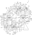
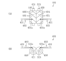
- FIG. 1 is a cross-sectional view taken along line II of FIG. 2 of a screw compressor according to an embodiment of the present invention.
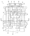
- FIG. 2 is a longitudinal sectional view showing a configuration of a main part of the screw compressor.
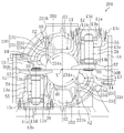
- FIG. 3 is a perspective view showing the screw rotor and the gate rotor.
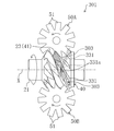
- FIG. 4 is a perspective view of the screw rotor and the gate rotor as seen from different angles.
- FIG. 5 is a plan view showing the operation of the compression mechanism according to the embodiment, where (A) shows the suction stroke, (B) shows the compression stroke, and (C) shows the discharge stroke.
- FIG. 6 is a cross-sectional view corresponding to FIG. 1 of the screw compressor according to the second embodiment.
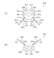
- FIG. 7 is a plan view showing a screw rotor and a gate rotor of the screw compressor according to the third embodiment.
- FIG. 8 is a schematic explanatory view showing an oil injection direction in a twin screw compressor according to another embodiment, wherein (A) is a plan view and (B) is a front view.
- FIG. 9 is a schematic explanatory view showing an oil injection direction in a twin screw compressor according to another embodiment, where (A) is a plan view and (B) is a front view.
- FIG. 10 is a schematic explanatory view showing an oil injection direction in a twin screw compressor according to still another embodiment, where (A) is a plan view and (B) is a front view.
- Embodiment 1 of the Invention The screw compressor (1) which concerns on Embodiment 1 of this invention is provided in the refrigerant circuit which performs a refrigerating cycle, and is for compressing a refrigerant
- the screw compressor (1) is configured as a semi-hermetic type.
- a compression mechanism (20) and an electric motor (not shown) for driving the compression mechanism (20) are accommodated in one casing (10).
- the compression mechanism (20) is connected to the electric motor via the drive shaft (21).
- a low-pressure gas refrigerant is introduced from the evaporator of the refrigerant circuit and the low-pressure space (S1) for guiding the low-pressure gas to the compression mechanism (20), and the compression mechanism (20)
- a high-pressure space (S2) into which the discharged high-pressure gas refrigerant flows is partitioned.
- the compression mechanism (20) includes one screw rotor (40) and a cylindrical wall (10) that forms a part of the casing (10) and that defines a screw rotor housing chamber (12) that houses the screw rotor (40). 11) and two gate rotors (50A, 50B) meshing with the screw rotor (40).
- the screw rotor (40) is a metal member formed in a substantially cylindrical shape.
- a plurality of spiral grooves (41, 41,...) Extending spirally from one end to the other end of the screw rotor (40) are formed on the outer peripheral portion of the screw rotor (40).
- the plurality of spiral grooves (41, 41,...) Are arranged at equal intervals.
- the screw rotor (40) is rotatably fitted to the cylindrical wall (11), and the outer peripheral surface thereof is in sliding contact with the inner peripheral surface of the cylindrical wall (11).
- the drive shaft (21) is inserted through the screw rotor (40).
- the screw rotor (40) and the drive shaft (21) are connected by a key (22).
- the drive shaft (21) is arranged coaxially with the screw rotor (40).
- the tip of the drive shaft (21) is a bearing holder (60) located on the high pressure space (S2) side of the compression mechanism (20) (right side when the axial direction of the drive shaft (21) in FIG. 2 is the left-right direction). ) Is rotatably supported.
- the bearing holder (60) supports the drive shaft (21) via a ball bearing (61).
- Each spiral groove (41) of the screw rotor (40) starts at one end side (left side in FIG. 4) in the axial direction of the screw rotor (40) and ends at the other end side (right side in FIG. 4). Yes.
- the screw rotor (40) has a tapered peripheral surface at one end surface in the axial direction.
- the starting end of the spiral groove (41) opens to the tapered surface, while the end of the spiral groove (41) opens to the outer peripheral surface of the screw rotor (40) and does not open to the other end surface in the axial direction.
- the screw rotor (40) is fitted in the cylindrical wall (11) so that the start side faces the low-pressure space (S1) side and the terminal side faces the high-pressure space (S2) (see FIG. 2). That is, the spiral groove (41) has a starting end opened to the low pressure space (S1). This starting end is the suction port (24) of the compression mechanism (20).
- the spiral groove (41) has a first side wall surface (42) positioned on the front side of the gate (51) described later of the gate rotor (50A (50B)) and a rear side of the gate (51) in the moving direction. It is comprised by the 2nd side wall surface (43) and the bottom wall surface (44) which are located.
- the two gate rotors (50A, 50B) are composed of an upward gate rotor (50A) whose surface faces upward and a downward gate rotor (50B) whose surface faces downward.
- Each gate rotor (50A (50B)) is a resin member having a plurality of gates (51, 51,...) Formed in a rectangular plate shape.
- the gate rotor (50A (50B)) is attached to a metal rotor support member (55).
- the rotor support member (55) includes a base portion (56), an arm portion (57), and a shaft portion (58).
- the base (56) is formed in a slightly thick disk shape.
- the arm part (57) is provided in the same number as the gate (51) of the gate rotor (50A (50B)), and extends radially outward from the outer peripheral surface of the base part (56).
- the shaft portion (58) is formed in a rod shape and is erected in a state of penetrating the base portion (56).
- the central axis of the shaft portion (58) coincides with the central axis of the base portion (56).
- the gate rotor (50A (50B)) is attached to the surface of the base portion (56) and the arm portion (57) opposite to the shaft portion (58). Each arm part (57) is in contact with the back surface of the gate (51).
- one end portion (hereinafter, also referred to as a protruding end portion) (58a) of the shaft portion (58) protrudes from the surface of the gate rotor (50A (50B)).
- the rotation axis of the gate rotor (50A (50B)) coincides with the central axis of the shaft portion (58).
- the two gate rotors (50A, 50B) are arranged on the outer side of the cylindrical wall (11) and are arranged symmetrically with respect to the rotational axis of the screw rotor (40). 13) Contained within.
- Each gate rotor storage chamber (13) communicates with the low pressure space (S1).
- the bearing housing (13a) constituting a part of the casing (10) is disposed in the gate rotor accommodating chamber (13).
- the bearing housing (13a) is a cylindrical member provided with a flange (13c) on the base end side, and is inserted into the gate rotor accommodating chamber (13) from the opening (11a) of the casing (11). 13c) is attached to the casing (11). Further, a lid member (13d) is attached to the flange (13c), and the bearing housing (13a) is formed in a bottomed cylindrical shape.
- ball bearings (13b, 13b) are provided at two locations on the top and bottom.
- the shaft portion (58) of the gate rotor (50B) is rotatably supported by the ball bearings (13b, 13b).
- This ball bearing (13b) constitutes a bearing portion.
- the cylindrical wall (11) is formed with an opening (11b) through which the gate rotor accommodating chamber (13, 13) communicates with the screw rotor accommodating chamber (12).
- the gate rotor (50A (50B)) accommodated in the gate rotor accommodating chamber (13) has a gate (51, 51,%) Through which the screw rotor (40) passes through the opening (11b) of the cylindrical wall (11). It arrange
- each gate rotor (50A (50B)) is disposed so that the surface thereof faces the rotational direction of the screw rotor (40), that is, faces the tangential direction of the screw rotor (40).
- the upward gate rotor (50A) is installed in such a posture that the surface faces vertically upward, while the shaft portion (58) faces vertically downward, and the downward gate rotor (50B), while the surface faces vertically downward,
- the shaft portion (58) is installed in a posture facing vertically upward.
- the gate (51) of the gate rotor (50A (50B)) meshes with the spiral groove (41) of the screw rotor (40), so that the inner peripheral surface of the cylindrical wall (11) and the spiral groove A compression chamber (23) is formed by the closed space surrounded by (41) and the gate (51). That is, the compression chamber (23) passes through the cylindrical space surrounded by the spiral groove (41) and the cylindrical wall (11) by the gate (51) from the start side and / or the end side of the spiral groove (41). Formed by closing.
- the screw compressor (1) is provided with a slide valve (7) as a capacity control mechanism.
- the slide valve (7) is provided in a slide valve accommodating chamber (14) in which a cylindrical wall (11) bulges radially outward at two locations in the circumferential direction.
- the slide valve (7) has an inner surface that forms part of the inner peripheral surface of the cylindrical wall (11) and is slidable in the axial direction of the cylindrical wall (11).
- a discharge passage (17) is formed on the outer peripheral surface side of the slide valve (7).
- the discharge passage (17) communicates with the high pressure space (S2).
- the slide valve (7) has a discharge port (73) for communicating the compression chamber (23) and the discharge passage (17).
- the casing (10) has a bypass passage (19) that is disconnected from the discharge passage (17) on the outer peripheral surface side of the slide valve (7) and close to the low-pressure space (S1). Yes.
- the bypass passage (19) communicates with the low pressure space (S1).
- the screw compressor (1) is provided with a slide valve drive mechanism (80) for slidingly driving the slide valve (7).
- the slide valve drive mechanism (80) includes a cylinder (81) fixed to the bearing holder (60), a piston (82) loaded in the cylinder (81), and a piston rod ( 83), a connecting rod (85) for connecting the arm (84) and the slide valve (7), and a spring for urging the arm (84) to the right in FIG. 86).
- the internal pressure of the left space of the piston (82) (the space on the screw rotor (40) side of the piston (82)) is the right space of the piston (82). It is higher than the internal pressure of the space on the arm (84) side of the piston (82).
- the slide valve drive mechanism (80) is configured to adjust the position of the slide valve (7) by adjusting the internal pressure in the right space of the piston (82) (ie, the gas pressure in the right space). ing.
- an oil supply mechanism (3, 3) for supplying oil to the screw rotor (40) and the gate rotor (50A, 50B) is formed on the cylindrical wall (11) of the casing (10). ing.
- This oil supply mechanism (3) constitutes an injection mechanism.
- the oil supply mechanism (3) includes an oil tank (not shown) in which high-pressure oil is stored, and an oil supply passage (30) for communicating the oil tank and the screw rotor storage chamber (12).
- the oil tank stores oil separated from the refrigerant discharged from the compression chamber (23).
- the oil is in a high pressure state due to the discharge pressure of the high pressure refrigerant.
- the oil supply passage (30) extends in the axial direction in the first passage (31) perforated so as to open from the outside of the casing (10) to the screw rotor storage chamber (12), and in the casing (10).
- the upstream end communicates with an oil tank (not shown), while the downstream end has a second passage (32) communicating with the first passage (31).
- a nozzle hole (31a) having an inner diameter smaller than that of the intermediate portion and opening to the screw rotor storage chamber (12) is formed.
- the nozzle hole (31a) is an intermediate position between the two gate rotors (50A, 50B) in the circumferential direction of the cylindrical wall (11), and immediately after the gate (51) is engaged in the axial direction of the cylindrical wall (11). It is formed at a position opening in the spiral groove (41) (see FIG. 5).
- the outer end of the casing (10) of the first passage (31) is sealed with a plug (31b).
- the axis of the first passage (31) is viewed in the axial direction of the screw rotor (40) (that is, in a cross-sectional view of the screw rotor (40) shown in FIG. 1), and the nozzle hole (31a) and the screw rotor ( The region of the screw rotor (40) rotating in the compression direction relative to the straight line connecting the axis (X) of 40) in which the spiral groove (41) moves away from the nozzle (31a) (in other words, It is inclined toward the gate rotor (50A (50B)) side meshing with the spiral groove (41) from the start end side.
- the screw rotor (40) rotates as the drive shaft (21) rotates.
- the gate rotor (50A, 50B) also rotates, and the compression mechanism (20) repeats the suction stroke, the compression stroke, and the discharge stroke.
- the compression chamber (23) formed in the region from the downward gate rotor (50B) to the upward gate rotor (50A) in the rotational direction of the screw rotor (40), that is, the starting end side of the spiral groove (41) is the upward gate.
- the compression chamber (23) that is closed by the rotor (50A) will be described.
- the spiral groove (41) with shading that is, the compression chamber (23)
- the spiral groove (41) in which the compression chamber (23) is formed meshes with the gate (51) of the downward gate rotor (50B) located on the lower side of the figure.
- the gate (51) relatively moves toward the terminal end of the spiral groove (41), and the volume of the compression chamber (23) increases accordingly.
- the low-pressure gas refrigerant in the low-pressure space (S1) is sucked into the compression chamber (23) through the suction port (24).
- FIG. 5 (B) When the screw rotor (40) further rotates, the state shown in FIG. 5 (B) is obtained.
- the compression chamber (23) with shading is completely closed. That is, the spiral groove (41) in which the compression chamber (23) is formed meshes with the gate (51) of the upward gate rotor (50A) located on the upper side of the figure, and the low pressure space is formed by the gate (51). It is partitioned from (S1).
- the gate (51) moves toward the end of the spiral groove (41) as the screw rotor (40) rotates, the volume of the compression chamber (23) gradually decreases. As a result, the gas refrigerant in the compression chamber (23) is compressed.
- the compression chamber (23) moves in the axial direction of the screw rotor (40) from the start end side to the end side in the axial direction of the screw rotor (40) as the screw rotor (40) rotates. Are moving relatively.
- the compression chamber (23) that moves in this way has moved to the position of the nozzle hole (31a) that opens in the cylindrical wall (11) immediately after being closed by the gate (51) (see FIG. 5B). ).
- the compression chamber (23) immediately after closing is at the same suction pressure as the low pressure space (S1).
- the oil in the oil tank passes through the second passage (32) and the first passage (31) from the nozzle (31a). It is injected into the compression chamber (23).
- the oil injected into the compression chamber (23) is sprayed on the wall surface of the spiral groove (41) and the inner peripheral surface of the cylindrical wall (11) and flows through the compression chamber (23) to the gate (51).
- the gate (51) is also sprayed. By doing so, the spiral groove (41) and the gate (51) are lubricated, and the gap between the spiral groove (41) and the gate (51) is filled with oil to improve the sealing performance.
- the injection direction of the oil injected from the nozzle hole (31a) is an area in which the spiral groove (41) moves away from the nozzle hole (31a) in the screw rotor (40) rotating in the compression direction (in other words, , Toward the gate rotor (50A (50B)) side meshing with the spiral groove (41) from the start end side (see FIG. 1).
- the oil injected into the compression chamber (23) flows in approximately the same direction as the direction of rotation of the screw rotor (40) during compression.
- the impact force includes a component in the direction of rotation of the screw rotor (40) when compressed. That is, rotational torque in the rotational direction during compression can be applied to the screw rotor (40) by the impact force of oil.
- the direction in which the spiral groove (41) moves away from the nozzle hole (31a) in the screw rotor (40) that rotates the injection direction of the oil injected from the nozzle hole (31a) in the rotation direction during compression It is possible to prevent the oil injected into the compression chamber (23) from interfering with the rotation of the screw rotor (40) during the compression, that is, the screw compressor ( It is possible to prevent the mechanical loss of 1) from increasing.
- the screw compressor (1) when the oil injected from the nozzle (31a) collides with the screw rotor (40), the screw compressor (1) is provided with a rotational torque for rotating the screw rotor (40) in the rotation direction during compression. Efficiency can be improved.
- the first side wall surface is located on the front side in the traveling direction of the gate (51) of the side wall surface (42, 43) of the spiral groove (41) when the oil sprayed from the nozzle hole (31a) is not closed. It is preferable that the oil injection direction is set so as to go to (42).
- the screw rotor (40) rotates in the rotational direction during compression, the spiral groove (41) is observed from a certain point outside the screw rotor (40), for example, from the point of the nozzle (31a).
- the direction from the suction side end portion to the discharge side end portion in the axial direction of the screw rotor (40) substantially coincides with the direction from the front side in the traveling direction of the gate (51). That is, by injecting oil toward the first side wall surface (42), the spiral groove (41) moves forward in the direction of travel of the gate (51), that is, the suction side end in the axial direction of the screw rotor (40). Can be applied to the screw rotor (40), that is, rotational torque can be applied to rotate the screw rotor (40) in the direction of rotation during compression. .
- the oil is not directed toward the first side wall surface (42), the oil is sprayed toward the bottom wall surface (44) and the oil is prevented from being sprayed toward the second side wall surface (43). It is preferable. That is, the nozzle hole (31a) blocked at the peak portion between the spiral grooves (41, 41) is a relative translation of the spiral groove (41) and the nozzle hole (31a) due to the rotation of the screw rotor (40). Immediately after opening the compression chamber (23), oil is injected toward the first side wall surface (42), and the relative movement of the spiral groove (41) and the injection port (31a) continues for a while.
- the oil continues toward the first side wall surface (42), and eventually the oil begins to move toward the bottom wall surface (44), and then the nozzle (31a) is again at the peak between the spiral grooves (41, 41). What is necessary is just to set the injection direction of the oil injected from a nozzle (31a) so that it may be blocked.
- positioning may be sufficient as a 1st and 2nd oil supply channel
- the axis of the first passage (31) is such that the spiral groove (41) moves away from the nozzle (31a) in the screw rotor (40) in which the oil injected from the nozzle (31a) rotates in the rotation direction during compression. As long as it goes to the moving area, it can be inclined at an arbitrary angle.
- Embodiment 2 of the Invention >> Next, a screw compressor (201) according to Embodiment 2 of the present invention will be described.
- the screw compressor (201) according to Embodiment 2 is different from the oil supply mechanism (3) according to Embodiment 1 in the position of the oil supply mechanism (203). Therefore, configurations similar to those of the first embodiment are denoted by the same reference numerals, description thereof is omitted, and different configurations are mainly described.
- the oil supply mechanism (203) has a nozzle hole (231a) formed in the vicinity of the gate rotor (50A (50B)). That is, the oil supply mechanism (203) is configured to inject oil toward the meshing portion between the gate (51) and the spiral groove (41).
- the axis of the first passage (231) is such that its axis is the outer peripheral surface of the screw rotor (40) at the meshing position of the spiral groove (41) and the gate (51) (that is, two adjacent spiral grooves (41, 41) is formed so as to extend parallel to the tangential direction of the screw rotor (40) at the mesh position at a position radially inward from the outer peripheral surface of the peak portion between 41).
- the first passage (231) is formed through the casing side passage (233) formed through the casing (10) and the slide valve (7).
- the casing side passage (233) and the valve side passage (234) communicate with each other.
- the nozzle hole (231a) is formed at the downstream end of the valve side passage (234).
- the slide valve (7) moves in the axial direction of the screw rotor (40), the downstream end of the casing side passage (233) and / or the upstream end of the valve side passage (234) is connected to the screw rotor (40). ) In the axial direction (not limited to the configuration in which the end is formed in the shape of a long hole, but may simply be expanded in diameter). By doing so, even if the slide valve (7) moves, the communication state between the casing side passage (233) and the valve side passage (234) is maintained.
- the axis of the first passage (231) is viewed from the axial direction of the screw rotor (40), and the nozzle hole (231a) and the screw rotor (40).
- the spiral groove (41) in the screw rotor (40) rotating in the compression direction is inclined toward the region moving in the direction away from the injection port (231a) rather than the straight line connecting the axis (X).
- the gate (51) and the spiral groove (41) are reliably lubricated.
- the gap between the gate (51) and the spiral groove (41) can be reliably sealed.
- Embodiment 3 of the Invention >> Next, a screw compressor (301) according to Embodiment 3 of the present invention will be described.
- the screw compressor (301) according to Embodiment 3 is different from the oil supply mechanism (3) according to Embodiment 1 in the position of the oil supply mechanism (303). Therefore, configurations similar to those of the first embodiment are denoted by the same reference numerals, description thereof is omitted, and different configurations are mainly described.
- the oil supply mechanism (303) includes a screw compressor (301) so that the oil injected from the injection port (331a) faces the starting end side in the extending direction of the spiral groove (41). ) Is configured.
- the nozzle hole (331a) of the first passage (331) is an intermediate position between the two gate rotors (50A, 50B) in the circumferential direction of the cylindrical wall (11), and the cylindrical wall (11 ) Is formed at a position where the gate (51) opens into the spiral groove (41) immediately after meshing.
- the first passage (331) is formed such that its axis extends in the extending direction of the spiral groove (41) at the position of the nozzle hole (331a), and injects oil toward the start end side of the spiral groove (41). Is configured to do.
- the screw rotor (40) rotates, the spiral groove (41) meshes with the gate (51) from the start end side, and disengages with the gate (51) at the end side. That is, the screw rotor (40) rotates from the terminal end side to the starting end side of the spiral groove (41) during compression. Therefore, as described above, by injecting oil from the injection port (331a) of the oil supply mechanism (303) toward the starting end side in the extending direction of the spiral groove (41), the screw rotor (40) is rotated in the compression direction. Oil can be injected in the direction of As a result, an increase in mechanical loss due to the injection of oil into the compression chamber (23) can be prevented. Furthermore, since the rotational torque can be applied to the screw rotor (40) in the direction from the terminal end side to the starting end side of the spiral groove (41), the efficiency of the screw compressor (1) can be improved.
- the axis of the first passage (331) may extend toward the bottom wall surface (43) of the spiral groove (41), or a tangent line drawn from the nozzle hole (331a) to the bottom wall surface (43). It may extend toward the inner peripheral surface of the cylindrical wall (11).
- the first to third embodiments are configured to inject oil into the compression chamber (23), but are not limited thereto.
- a so-called economizer type screw compressor that injects an intermediate-pressure gas refrigerant into the compression chamber (23) can adopt the same configuration, and the compression chamber (23) can also be a liquid refrigerant. Even if it is a screw compressor which injects, the same composition can be adopted.
- the axis of the first passage (31, 231) that is, the injection direction from the injection port (31a, 231a) extends in a plane orthogonal to the axis of the screw rotor (40). It is not limited to this.
- the injection direction is set so that the upstream side in the injection direction is located on the axial suction end side of the screw rotor (40) and the downstream side in the injection direction is located on the axial discharge end side of the screw rotor (40).
- 231a) may be tilted with respect to a perpendicular drawn from the axis (X) of the screw rotor (40).
- the single screw compressor has been described.
- the present invention is not limited to this, and the present invention may be applied to a twin screw compressor.
- the twin screw compressor (401) includes a male rotor (440) that is a screw rotor, a female rotor (450) that is a screw rotor, and the male rotor (440) and the female rotor (450). ) (Not shown).
- a plurality of spiral walls (444, 444,...) Are formed on the outer peripheral surface of the male rotor (440), and a spiral groove (441) is formed between the spiral walls (444, 444).
- a plurality of spiral grooves (454, 454,...) Are formed on the outer peripheral surface of the female rotor (450), and a spiral groove (451) is formed between the spiral walls (454, 454).
- the male rotor (440) and the female rotor (450) are arranged in a casing (not shown) such that the drive shafts (421,521) are parallel to each other and the spiral walls (444,454) are engaged with each other. Yes.
- the twin screw compressor (401) configured as described above includes a male side and a female side oil supply mechanism (403, 403) for supplying oil to the male rotor (440) and the female rotor (450).
- the male-side and female-side oil supply mechanisms (403, 403) are aligned on a plane in which the axis of each first passage (431, 431) is parallel to a plane including the axis of the male rotor (440) and the axis of the female rotor (450). It is arranged to line up. Further, the axis of each first passage (431) is parallel to the tangential direction of the outer peripheral surface (the outer peripheral surface of the spiral groove or the bottom surface of the spiral groove) around the axis of the rotor (440 (450)).
- the axis of each first passage (431) is the axis of the rotor (440 (450)). It is orthogonal to the heart. From the nozzle (431a) of the male-side oil supply mechanism (403) thus configured, oil is injected toward the spiral groove (441) of the male rotor (440), and the nozzle (431a) of the female-side oil supply mechanism (403) ) Oil is injected toward the spiral groove (451) of the female rotor (450).
- each oil supply mechanism (403) injects oil in the direction in which the rotor (440 (450)) rotates, in other words, the spiral groove (441 (451) in the rotor (440 (450)). )) Injects oil toward the region moving away from the nozzle (431a).
- the spiral grooves (441, 451) in the male rotor (440) and the female rotor (450) that rotate the injection direction of the oil injected from the injection holes (431a, 431a) in the rotation direction during compression are respectively provided.
- the oil injected into the compression chamber is prevented from obstructing the rotation of the male rotor (440) and female rotor (450) during compression. That is, it is possible to prevent the mechanical loss of the twin screw compressor (401) from increasing.
- the oil injected from the injection port (531a) of the male oil supply mechanism (503) is the side wall surface of the spiral groove (441) of the male rotor (440) ( 442, 443) is injected toward the first side wall surface (442) located on the front side in the axial direction of the spiral groove (441), and similarly, the nozzle hole (531a) of the female oil supply mechanism (503) ) Of the spiral groove (451) of the female rotor (450), the first side wall surface (452) located on the front side of the spiral groove (451) in the axial direction of the spiral groove (451). It may be injected so as to go to.
- the impact force component that moves from the suction side end to the discharge side end in the axial direction of the male rotor (440) and female rotor (450).
- the oil injected from the injection port (631a) of the male side oil supply mechanism (603) is in the extending direction of the spiral groove (441) of the male rotor (440). Along the spiral groove (441) toward the starting end side.
- the oil injected from the nozzle (631a) of the female oil supply mechanism (603) is injected into the spiral groove (451) of the female rotor (450). You may inject
- the male rotor (440) and the female rotor (450) Oil can be injected in a direction along the rotation direction during compression.
- an increase in mechanical loss due to the injection of oil into the compression chamber can be prevented.
- the rotational torque can be applied to the male rotor (440) and the female rotor (450) in the direction from the terminal end side to the starting end side of the spiral groove (441,451), the efficiency of the twin screw compressor (401) is improved. be able to.
- the present invention is useful for a screw compressor that supplies oil or gas to a compression chamber.
Landscapes
- Engineering & Computer Science (AREA)
- Mechanical Engineering (AREA)
- General Engineering & Computer Science (AREA)
- Applications Or Details Of Rotary Compressors (AREA)
Abstract
L'invention porte sur un compresseur à vis dans lequel la perte mécanique du compresseur n'augmente pas lorsque de l'huile ou un fluide de refroidissement est injecté dans une chambre de compression. Le compresseur à vis (1) comporte un rotor à vis (40) et des rotors à ailettes (50A, 50B), et comprime un fluide de refroidissement, aspiré à partir du côté de point de commencement d'une rainure hélicoïdale (41), dans une chambre de compression (23) formée par la rainure hélicoïdale (41) et des ailettes (51), et décharge le fluide de refroidissement à partir du côté de point de fin de la rainure hélicoïdale (41). Le compresseur à vis (1) comporte également un mécanisme d'alimentation en huile (3) pour injecter de l'huile dans la chambre de compression (23) à partir d'une buse (31a). Le mécanisme d'alimentation en huile (3) éjecte l'huile vers le rotor à vis (40) de telle sorte que le couple de rotation dans le sens de rotation du rotor à vis (40) lors d'une opération de compression est appliqué au rotor à vis (40).
Priority Applications (3)
| Application Number | Priority Date | Filing Date | Title |
|---|---|---|---|
| US12/864,087 US8708677B2 (en) | 2008-01-23 | 2009-01-23 | Screw compressor having injection having injection mechanism that injects oil or refrigerant toward a starting end of an extending direction of a helical groove of the female rotor or the male rotor |
| CN2009801030139A CN101925745B (zh) | 2008-01-23 | 2009-01-23 | 螺杆压缩机 |
| EP09703665.1A EP2246571A4 (fr) | 2008-01-23 | 2009-01-23 | Compresseur à vis |
Applications Claiming Priority (2)
| Application Number | Priority Date | Filing Date | Title |
|---|---|---|---|
| JP2008-012350 | 2008-01-23 | ||
| JP2008012350 | 2008-01-23 |
Publications (1)
| Publication Number | Publication Date |
|---|---|
| WO2009093469A1 true WO2009093469A1 (fr) | 2009-07-30 |
Family
ID=40900978
Family Applications (1)
| Application Number | Title | Priority Date | Filing Date |
|---|---|---|---|
| PCT/JP2009/000266 WO2009093469A1 (fr) | 2008-01-23 | 2009-01-23 | Compresseur à vis |
Country Status (5)
| Country | Link |
|---|---|
| US (1) | US8708677B2 (fr) |
| EP (1) | EP2246571A4 (fr) |
| JP (1) | JP4315237B1 (fr) |
| CN (1) | CN101925745B (fr) |
| WO (1) | WO2009093469A1 (fr) |
Families Citing this family (10)
| Publication number | Priority date | Publication date | Assignee | Title |
|---|---|---|---|---|
| WO2013078132A1 (fr) * | 2011-11-22 | 2013-05-30 | Vilter Manufacturing Llc | Appareil de detente/compression monovis |
| US9057373B2 (en) | 2011-11-22 | 2015-06-16 | Vilter Manufacturing Llc | Single screw compressor with high output |
| JP5527396B1 (ja) * | 2012-12-17 | 2014-06-18 | ダイキン工業株式会社 | スクリュー圧縮機 |
| JP6121000B2 (ja) * | 2014-01-29 | 2017-04-26 | 三菱電機株式会社 | スクリュー圧縮機 |
| CN110446857B (zh) | 2017-02-09 | 2021-12-14 | 大金工业株式会社 | 螺杆压缩机 |
| US10895259B2 (en) | 2018-04-20 | 2021-01-19 | Trane International Inc. | Screw compressor having synchronized economizer ports |
| US10876531B2 (en) | 2018-12-26 | 2020-12-29 | Trane International Inc. | Lubricant injection for a screw compressor |
| GB2581204B (en) * | 2019-02-11 | 2022-07-20 | J & E Hall Ltd | Screw compressor |
| JP7356044B2 (ja) * | 2021-03-31 | 2023-10-04 | ダイキン工業株式会社 | スクリュー圧縮機、および冷凍装置 |
| CN115045833B (zh) * | 2022-06-22 | 2023-06-16 | 好米动力设备有限公司 | 一种双螺杆三星轮压缩机 |
Citations (4)
| Publication number | Priority date | Publication date | Assignee | Title |
|---|---|---|---|---|
| JPH02248678A (ja) | 1989-03-20 | 1990-10-04 | Daikin Ind Ltd | スクリュー圧縮機 |
| JPH05106572A (ja) * | 1991-10-17 | 1993-04-27 | Daikin Ind Ltd | 一軸形スクリユー圧縮機 |
| JPH09151870A (ja) * | 1995-12-04 | 1997-06-10 | Hitachi Ltd | 油冷式スクリュー圧縮機 |
| JP2008267222A (ja) * | 2007-04-18 | 2008-11-06 | Kobe Steel Ltd | 液冷式スクリュ圧縮機 |
Family Cites Families (9)
| Publication number | Priority date | Publication date | Assignee | Title |
|---|---|---|---|---|
| US3133695A (en) * | 1960-06-22 | 1964-05-19 | Zimmern Fernand | Compressors |
| US3752606A (en) * | 1971-12-14 | 1973-08-14 | B Zimmern | Liquid injection system for globoid-worm compressor |
| JPS5930919B2 (ja) * | 1974-12-24 | 1984-07-30 | 北越工業 (株) | 液冷式回転圧縮機の液量及び気体容量調整装置 |
| SE388463B (sv) * | 1975-01-24 | 1976-10-04 | Atlas Copco Ab | Forfarande och anordning for drenering av vetska fran en vetskeavskiljare |
| US4227867A (en) * | 1978-03-06 | 1980-10-14 | Chicago Pneumatic Tool Company | Globoid-worm compressor with single piece housing |
| JPH07117052B2 (ja) * | 1991-04-12 | 1995-12-18 | 株式会社神戸製鋼所 | 無給油式注液形スクリュ圧縮機 |
| JP2001090684A (ja) * | 1999-09-22 | 2001-04-03 | Daikin Ind Ltd | スクリュー圧縮機および冷凍装置 |
| JP2004162540A (ja) * | 2002-11-11 | 2004-06-10 | Kobe Steel Ltd | スクリュ圧縮機 |
| DE10258145A1 (de) * | 2002-12-03 | 2004-06-24 | Bitzer Kühlmaschinenbau Gmbh | Schraubenverdichter |
-
2009
- 2009-01-23 US US12/864,087 patent/US8708677B2/en not_active Expired - Fee Related
- 2009-01-23 CN CN2009801030139A patent/CN101925745B/zh not_active Expired - Fee Related
- 2009-01-23 JP JP2009012994A patent/JP4315237B1/ja not_active Expired - Fee Related
- 2009-01-23 WO PCT/JP2009/000266 patent/WO2009093469A1/fr active Application Filing
- 2009-01-23 EP EP09703665.1A patent/EP2246571A4/fr not_active Withdrawn
Patent Citations (4)
| Publication number | Priority date | Publication date | Assignee | Title |
|---|---|---|---|---|
| JPH02248678A (ja) | 1989-03-20 | 1990-10-04 | Daikin Ind Ltd | スクリュー圧縮機 |
| JPH05106572A (ja) * | 1991-10-17 | 1993-04-27 | Daikin Ind Ltd | 一軸形スクリユー圧縮機 |
| JPH09151870A (ja) * | 1995-12-04 | 1997-06-10 | Hitachi Ltd | 油冷式スクリュー圧縮機 |
| JP2008267222A (ja) * | 2007-04-18 | 2008-11-06 | Kobe Steel Ltd | 液冷式スクリュ圧縮機 |
Non-Patent Citations (1)
| Title |
|---|
| See also references of EP2246571A4 * |
Also Published As
| Publication number | Publication date |
|---|---|
| EP2246571A1 (fr) | 2010-11-03 |
| JP4315237B1 (ja) | 2009-08-19 |
| US20100329918A1 (en) | 2010-12-30 |
| US8708677B2 (en) | 2014-04-29 |
| EP2246571A4 (fr) | 2014-11-26 |
| CN101925745A (zh) | 2010-12-22 |
| CN101925745B (zh) | 2013-04-10 |
| JP2009197794A (ja) | 2009-09-03 |
Similar Documents
| Publication | Publication Date | Title |
|---|---|---|
| JP4315237B1 (ja) | スクリュー圧縮機 | |
| KR102234708B1 (ko) | 스크롤 압축기 | |
| JP5765379B2 (ja) | スクロール圧縮機 | |
| JP4311500B2 (ja) | スクリュー圧縮機 | |
| KR101320196B1 (ko) | 회전식 압축기 | |
| JP5655850B2 (ja) | スクロール型圧縮機 | |
| JP2011021608A5 (fr) | ||
| JP7300312B2 (ja) | スクロール圧縮機 | |
| JP5812083B2 (ja) | スクロール型圧縮機 | |
| JP5943101B1 (ja) | スクリュー圧縮機 | |
| CN221347264U (zh) | 螺杆压缩机以及制冷装置 | |
| JP2006307753A (ja) | スクロール膨張機 | |
| JP6805793B2 (ja) | 圧縮機 | |
| JP2010150946A (ja) | スクロール圧縮機 | |
| JP7341003B2 (ja) | 横置型電動圧縮機 | |
| CN215256781U (zh) | 压缩机 | |
| KR102407603B1 (ko) | 압축기 | |
| JP2004316586A (ja) | スクリュー圧縮機 | |
| US20230175507A1 (en) | Compressor | |
| JP2019019678A (ja) | スクリュー圧縮機 | |
| JP2015001217A (ja) | 圧縮機 | |
| JP3172322B2 (ja) | 回転式スクロール圧縮機 | |
| JP2017002734A (ja) | ロータリー圧縮機 | |
| JP6464583B2 (ja) | 回転式圧縮機 | |
| JP2018009497A (ja) | 回転式圧縮機 |
Legal Events
| Date | Code | Title | Description |
|---|---|---|---|
| WWE | Wipo information: entry into national phase |
Ref document number: 200980103013.9 Country of ref document: CN |
|
| 121 | Ep: the epo has been informed by wipo that ep was designated in this application |
Ref document number: 09703665 Country of ref document: EP Kind code of ref document: A1 |
|
| WWE | Wipo information: entry into national phase |
Ref document number: 12864087 Country of ref document: US |
|
| NENP | Non-entry into the national phase |
Ref country code: DE |
|
| WWE | Wipo information: entry into national phase |
Ref document number: 2009703665 Country of ref document: EP |