WO2009093469A1 - Screw compressor - Google Patents
Screw compressor Download PDFInfo
- Publication number
- WO2009093469A1 WO2009093469A1 PCT/JP2009/000266 JP2009000266W WO2009093469A1 WO 2009093469 A1 WO2009093469 A1 WO 2009093469A1 JP 2009000266 W JP2009000266 W JP 2009000266W WO 2009093469 A1 WO2009093469 A1 WO 2009093469A1
- Authority
- WO
- WIPO (PCT)
- Prior art keywords
- spiral groove
- rotor
- oil
- screw
- screw rotor
- Prior art date
Links
Images


Classifications
-
- F—MECHANICAL ENGINEERING; LIGHTING; HEATING; WEAPONS; BLASTING
- F04—POSITIVE - DISPLACEMENT MACHINES FOR LIQUIDS; PUMPS FOR LIQUIDS OR ELASTIC FLUIDS
- F04C—ROTARY-PISTON, OR OSCILLATING-PISTON, POSITIVE-DISPLACEMENT MACHINES FOR LIQUIDS; ROTARY-PISTON, OR OSCILLATING-PISTON, POSITIVE-DISPLACEMENT PUMPS
- F04C29/00—Component parts, details or accessories of pumps or pumping installations, not provided for in groups F04C18/00 - F04C28/00
- F04C29/04—Heating; Cooling; Heat insulation
- F04C29/042—Heating; Cooling; Heat insulation by injecting a fluid
-
- F—MECHANICAL ENGINEERING; LIGHTING; HEATING; WEAPONS; BLASTING
- F04—POSITIVE - DISPLACEMENT MACHINES FOR LIQUIDS; PUMPS FOR LIQUIDS OR ELASTIC FLUIDS
- F04C—ROTARY-PISTON, OR OSCILLATING-PISTON, POSITIVE-DISPLACEMENT MACHINES FOR LIQUIDS; ROTARY-PISTON, OR OSCILLATING-PISTON, POSITIVE-DISPLACEMENT PUMPS
- F04C18/00—Rotary-piston pumps specially adapted for elastic fluids
- F04C18/48—Rotary-piston pumps with non-parallel axes of movement of co-operating members
- F04C18/50—Rotary-piston pumps with non-parallel axes of movement of co-operating members the axes being arranged at an angle of 90 degrees
- F04C18/52—Rotary-piston pumps with non-parallel axes of movement of co-operating members the axes being arranged at an angle of 90 degrees of intermeshing engagement type, i.e. with engagement of co-operating members similar to that of toothed gearing
-
- F—MECHANICAL ENGINEERING; LIGHTING; HEATING; WEAPONS; BLASTING
- F04—POSITIVE - DISPLACEMENT MACHINES FOR LIQUIDS; PUMPS FOR LIQUIDS OR ELASTIC FLUIDS
- F04C—ROTARY-PISTON, OR OSCILLATING-PISTON, POSITIVE-DISPLACEMENT MACHINES FOR LIQUIDS; ROTARY-PISTON, OR OSCILLATING-PISTON, POSITIVE-DISPLACEMENT PUMPS
- F04C18/00—Rotary-piston pumps specially adapted for elastic fluids
- F04C18/08—Rotary-piston pumps specially adapted for elastic fluids of intermeshing-engagement type, i.e. with engagement of co-operating members similar to that of toothed gearing
- F04C18/12—Rotary-piston pumps specially adapted for elastic fluids of intermeshing-engagement type, i.e. with engagement of co-operating members similar to that of toothed gearing of other than internal-axis type
- F04C18/14—Rotary-piston pumps specially adapted for elastic fluids of intermeshing-engagement type, i.e. with engagement of co-operating members similar to that of toothed gearing of other than internal-axis type with toothed rotary pistons
- F04C18/16—Rotary-piston pumps specially adapted for elastic fluids of intermeshing-engagement type, i.e. with engagement of co-operating members similar to that of toothed gearing of other than internal-axis type with toothed rotary pistons with helical teeth, e.g. chevron-shaped, screw type
Definitions
- the present invention relates to a screw compressor in which oil or refrigerant is injected into a compression chamber.
- a compressor for compressing refrigerant or air a single screw compressor including one screw rotor, a casing for housing the screw rotor, and two gate rotors is known (see Patent Document 1).
- a compression chamber is formed by the gate of the gate rotor meshing with the spiral groove of the screw rotor, and the refrigerant in the compression chamber is compressed by the rotation of the screw rotor and the gate rotor.
- oil is injected into the compression chamber in order to lubricate the spiral groove and the gate and to improve the sealing performance of the gap between the spiral groove and the gate.
- oil or refrigerant hereinafter also referred to as oil or the like
- the injected oil or the like may become a resistance of the rotating screw rotor, resulting in a mechanical loss.
- the present invention has been made in view of such points, and an object thereof is to prevent an increase in mechanical loss when oil or refrigerant is injected into a compression chamber.
- a screw rotor (40) having a plurality of spiral grooves (41, 41,...) And a plurality of gates (51, 51,...) Meshing with the spiral grooves (41, 41,).
- a gate rotor (50A, 50B) Provided with a gate rotor (50A, 50B), and sucked from the start end side of the spiral groove (41) in a compression chamber (23) formed by the spiral groove (41) and the gate (51)
- the target is a screw compressor that compresses the discharged refrigerant and discharges it from the terminal end side of the spiral groove (41).
- the injection mechanism (3) further injects oil or refrigerant into the compression chamber (23) from the nozzle (31a), and the injection mechanism (3) rotates in a direction in which the screw rotor (40) rotates during compression. Oil or refrigerant is jetted onto the screw rotor (40) so as to give rotational torque.
- the oil or the like injected from the injection mechanism (3) gives rotational torque to the screw rotor (40) in the direction of rotation during compression (hereinafter also referred to as the rotation direction during compression). Therefore, the injected oil or the like does not become a resistance to rotation of the screw rotor (40) during compression, and conversely, rotation can be assisted. As a result, an increase in mechanical loss can be prevented, and further, the efficiency of the compressor can be improved.
- the injection mechanism (3) moves the spiral groove (41) away from the nozzle (31a) in the rotating screw rotor (40). Oil or refrigerant shall be injected toward the area.
- the rotating screw rotor (40) when the rotating screw rotor (40) is divided by a plane including the axis (X) and the injection port (31a) of the injection mechanism (3), one region has a spiral groove (41). It rotates so that it may approach a nozzle hole (31a), and the other area
- the injection mechanism (3) injects oil or the like into a region where the spiral groove (41) is moving away from the injection port (31a).
- the tangential direction component of the impact force such as oil injected from the injection mechanism (3) and colliding with the screw rotor (40) matches the rotational direction of the screw rotor (40) when compressed.
- a rotational torque in the rotational direction during compression can be applied to the rotor (40). As a result, an increase in mechanical loss can be prevented, and further, the efficiency of the compressor can be improved.
- the injection mechanism (3) is configured so that the screw rotor has a vertical line extending from the nozzle (31a) to the axis (X) of the screw rotor (40). In the axial direction of (40), oil or refrigerant is jetted to the discharge side end of the screw rotor (40).
- the spiral groove (41) when the spiral groove (41) is observed from a certain point on the outer peripheral side of the screw rotor (40), for example, the point of the nozzle (31a) when the screw rotor (40) rotates, the spiral The groove (41) appears to move in the axial direction of the screw rotor (40) from the end on the suction side to the end on the discharge side. That is, the oil or refrigerant from the injection mechanism (3) is discharged to the end on the discharge side in the axial direction of the screw rotor (40) with respect to the vertical line drawn from the nozzle (31a) to the axis (X) of the screw rotor (40).
- the spiral groove (41) is directed in the axial direction of the screw rotor (40) from the suction side end to the discharge side end with respect to the screw rotor (40).
- Rotational torque can be applied in the direction of movement, that is, in the rotational direction during compression.
- the 4th invention is the screw rotor (40) in which several spiral groove (41,41, ...) was formed, and several gate (51,51, ...) meshing with this spiral groove (41,41, ).
- a gate rotor (50A, 50B) Provided with a gate rotor (50A, 50B), and sucked from the start end side of the spiral groove (41) in a compression chamber (23) formed by the spiral groove (41) and the gate (51)
- the target is a screw compressor that compresses the discharged refrigerant and discharges it from the terminal end side of the spiral groove (41).
- the injection mechanism (3) further injects oil or refrigerant into the compression chamber (23) from the injection port (31a), and the injection mechanism (3) includes the side wall surfaces (42, 43) of the spiral groove (41). ), Oil or refrigerant is jetted toward the side wall surface (42) on the front side in the traveling direction of the gate meshed with the spiral groove (41).
- the fifth invention is a screw rotor (40) having a plurality of spiral grooves (41, 41,%) And a plurality of gates (51, 51,...) Meshing with the spiral grooves (41, 41,). ) Provided with a gate rotor (50A, 50B), and sucked from the start end side of the spiral groove (41) in a compression chamber (23) formed by the spiral groove (41) and the gate (51)
- the target is a screw compressor that compresses the discharged refrigerant and discharges it from the terminal end side of the spiral groove (41).
- injection mechanism (303) for injecting oil or refrigerant into the compression chamber (23) from the nozzle hole (331a), and the injection mechanism (303) is the starting end side in the extending direction in which the spiral groove (41) extends. Oil or refrigerant shall be injected toward the nozzle hole (331a)
- the screw rotor (40) rotates so that the spiral groove (41) meshes with the gate rotor from the start end side and the meshing is released at the end end side. That is, the screw rotor (40) rotates from the terminal end side to the starting end side of the spiral groove (41). Therefore, in the configuration in which the injection mechanism (3) injects oil or the like to the screw rotor (40), the oil or refrigerant is injected toward the starting end side in the extending direction of the spiral groove (41), so that the rotational direction during compression Therefore, it is possible to prevent the screw rotor (40) rotating in the direction from being hindered from rotating, and to prevent an increase in mechanical loss. Furthermore, rotational torque in the rotational direction during compression can be applied to the screw rotor (40), and the efficiency of the compressor can be improved.
- the screw compressor is configured such that oil from the injection mechanism (3) is injected in a direction in which a rotational torque in the rotational direction during compression is applied to the screw rotor (40). Can reduce mechanical loss when rotating the screw rotor (40) due to oil or the like injected into the compression chamber, and can further improve the efficiency of the compressor by applying rotational torque. it can.
- the oil from the said injection mechanism (3) injects toward the area
- a rotational torque is applied in the rotational direction in which the spiral groove (41) moves away from the injection port (31a), that is, in the direction in which the screw rotor (40) is rotating. be able to.
- rotational torque in the rotational direction during compression can be applied to the screw rotor (40) by the impact force of the injected oil or the like.
- the oil from the injection mechanism (3) is more perpendicular to the screw rotor (40) than the vertical line drawn from the nozzle (31a) to the axis (X) of the screw rotor (40).
- the spiral groove (41) is configured such that the screw compressor is configured to be injected toward the discharge side end of the screw rotor (40) in the axial direction of the screw rotor (40).
- Can exert an impact force such as oil in the direction of movement in the axial direction of the screw rotor (40), and as a result, a rotational torque in the rotational direction during compression is applied to the screw rotor (40).
- the oil etc. from the said injection mechanism (3) advance of the said gate which meshes with this spiral groove (41) among the side wall surfaces (42,43) of the said spiral groove (41).
- the screw compressor By configuring the screw compressor so as to be injected toward the side wall surface (42) on the front side in the direction, oil or the like is moved in the direction of moving the side wall surface (42) of the spiral groove (41) in the moving direction of the gate. An impact force can be applied, and as a result, rotational torque in the rotational direction during compression can be applied to the screw rotor (40).
- the screw compressor is configured such that the oil or the like from the injection mechanism (303) is jetted toward the starting end side in the extending direction of the spiral groove (41).
- An impact force such as oil can be applied to the rotor (40) in a direction in which the spiral groove (41) rotates from the terminal end side toward the starting end side.
- the screw rotor (40) is compressed.
- a rotational torque in the rotational direction can be applied.
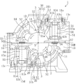
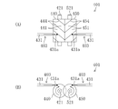
- FIG. 1 is a cross-sectional view taken along line II of FIG. 2 of a screw compressor according to an embodiment of the present invention.
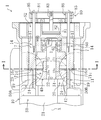
- FIG. 2 is a longitudinal sectional view showing a configuration of a main part of the screw compressor.
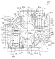
- FIG. 3 is a perspective view showing the screw rotor and the gate rotor.
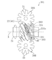
- FIG. 4 is a perspective view of the screw rotor and the gate rotor as seen from different angles.
- FIG. 5 is a plan view showing the operation of the compression mechanism according to the embodiment, where (A) shows the suction stroke, (B) shows the compression stroke, and (C) shows the discharge stroke.
- FIG. 6 is a cross-sectional view corresponding to FIG. 1 of the screw compressor according to the second embodiment.
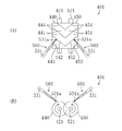
- FIG. 7 is a plan view showing a screw rotor and a gate rotor of the screw compressor according to the third embodiment.
- FIG. 8 is a schematic explanatory view showing an oil injection direction in a twin screw compressor according to another embodiment, wherein (A) is a plan view and (B) is a front view.
- FIG. 9 is a schematic explanatory view showing an oil injection direction in a twin screw compressor according to another embodiment, where (A) is a plan view and (B) is a front view.
- FIG. 10 is a schematic explanatory view showing an oil injection direction in a twin screw compressor according to still another embodiment, where (A) is a plan view and (B) is a front view.
- Embodiment 1 of the Invention The screw compressor (1) which concerns on Embodiment 1 of this invention is provided in the refrigerant circuit which performs a refrigerating cycle, and is for compressing a refrigerant
- the screw compressor (1) is configured as a semi-hermetic type.
- a compression mechanism (20) and an electric motor (not shown) for driving the compression mechanism (20) are accommodated in one casing (10).
- the compression mechanism (20) is connected to the electric motor via the drive shaft (21).
- a low-pressure gas refrigerant is introduced from the evaporator of the refrigerant circuit and the low-pressure space (S1) for guiding the low-pressure gas to the compression mechanism (20), and the compression mechanism (20)
- a high-pressure space (S2) into which the discharged high-pressure gas refrigerant flows is partitioned.
- the compression mechanism (20) includes one screw rotor (40) and a cylindrical wall (10) that forms a part of the casing (10) and that defines a screw rotor housing chamber (12) that houses the screw rotor (40). 11) and two gate rotors (50A, 50B) meshing with the screw rotor (40).
- the screw rotor (40) is a metal member formed in a substantially cylindrical shape.
- a plurality of spiral grooves (41, 41,...) Extending spirally from one end to the other end of the screw rotor (40) are formed on the outer peripheral portion of the screw rotor (40).
- the plurality of spiral grooves (41, 41,...) Are arranged at equal intervals.
- the screw rotor (40) is rotatably fitted to the cylindrical wall (11), and the outer peripheral surface thereof is in sliding contact with the inner peripheral surface of the cylindrical wall (11).
- the drive shaft (21) is inserted through the screw rotor (40).
- the screw rotor (40) and the drive shaft (21) are connected by a key (22).
- the drive shaft (21) is arranged coaxially with the screw rotor (40).
- the tip of the drive shaft (21) is a bearing holder (60) located on the high pressure space (S2) side of the compression mechanism (20) (right side when the axial direction of the drive shaft (21) in FIG. 2 is the left-right direction). ) Is rotatably supported.
- the bearing holder (60) supports the drive shaft (21) via a ball bearing (61).
- Each spiral groove (41) of the screw rotor (40) starts at one end side (left side in FIG. 4) in the axial direction of the screw rotor (40) and ends at the other end side (right side in FIG. 4). Yes.
- the screw rotor (40) has a tapered peripheral surface at one end surface in the axial direction.
- the starting end of the spiral groove (41) opens to the tapered surface, while the end of the spiral groove (41) opens to the outer peripheral surface of the screw rotor (40) and does not open to the other end surface in the axial direction.
- the screw rotor (40) is fitted in the cylindrical wall (11) so that the start side faces the low-pressure space (S1) side and the terminal side faces the high-pressure space (S2) (see FIG. 2). That is, the spiral groove (41) has a starting end opened to the low pressure space (S1). This starting end is the suction port (24) of the compression mechanism (20).
- the spiral groove (41) has a first side wall surface (42) positioned on the front side of the gate (51) described later of the gate rotor (50A (50B)) and a rear side of the gate (51) in the moving direction. It is comprised by the 2nd side wall surface (43) and the bottom wall surface (44) which are located.
- the two gate rotors (50A, 50B) are composed of an upward gate rotor (50A) whose surface faces upward and a downward gate rotor (50B) whose surface faces downward.
- Each gate rotor (50A (50B)) is a resin member having a plurality of gates (51, 51,...) Formed in a rectangular plate shape.
- the gate rotor (50A (50B)) is attached to a metal rotor support member (55).
- the rotor support member (55) includes a base portion (56), an arm portion (57), and a shaft portion (58).
- the base (56) is formed in a slightly thick disk shape.
- the arm part (57) is provided in the same number as the gate (51) of the gate rotor (50A (50B)), and extends radially outward from the outer peripheral surface of the base part (56).
- the shaft portion (58) is formed in a rod shape and is erected in a state of penetrating the base portion (56).
- the central axis of the shaft portion (58) coincides with the central axis of the base portion (56).
- the gate rotor (50A (50B)) is attached to the surface of the base portion (56) and the arm portion (57) opposite to the shaft portion (58). Each arm part (57) is in contact with the back surface of the gate (51).
- one end portion (hereinafter, also referred to as a protruding end portion) (58a) of the shaft portion (58) protrudes from the surface of the gate rotor (50A (50B)).
- the rotation axis of the gate rotor (50A (50B)) coincides with the central axis of the shaft portion (58).
- the two gate rotors (50A, 50B) are arranged on the outer side of the cylindrical wall (11) and are arranged symmetrically with respect to the rotational axis of the screw rotor (40). 13) Contained within.
- Each gate rotor storage chamber (13) communicates with the low pressure space (S1).
- the bearing housing (13a) constituting a part of the casing (10) is disposed in the gate rotor accommodating chamber (13).
- the bearing housing (13a) is a cylindrical member provided with a flange (13c) on the base end side, and is inserted into the gate rotor accommodating chamber (13) from the opening (11a) of the casing (11). 13c) is attached to the casing (11). Further, a lid member (13d) is attached to the flange (13c), and the bearing housing (13a) is formed in a bottomed cylindrical shape.
- ball bearings (13b, 13b) are provided at two locations on the top and bottom.
- the shaft portion (58) of the gate rotor (50B) is rotatably supported by the ball bearings (13b, 13b).
- This ball bearing (13b) constitutes a bearing portion.
- the cylindrical wall (11) is formed with an opening (11b) through which the gate rotor accommodating chamber (13, 13) communicates with the screw rotor accommodating chamber (12).
- the gate rotor (50A (50B)) accommodated in the gate rotor accommodating chamber (13) has a gate (51, 51,%) Through which the screw rotor (40) passes through the opening (11b) of the cylindrical wall (11). It arrange
- each gate rotor (50A (50B)) is disposed so that the surface thereof faces the rotational direction of the screw rotor (40), that is, faces the tangential direction of the screw rotor (40).
- the upward gate rotor (50A) is installed in such a posture that the surface faces vertically upward, while the shaft portion (58) faces vertically downward, and the downward gate rotor (50B), while the surface faces vertically downward,
- the shaft portion (58) is installed in a posture facing vertically upward.
- the gate (51) of the gate rotor (50A (50B)) meshes with the spiral groove (41) of the screw rotor (40), so that the inner peripheral surface of the cylindrical wall (11) and the spiral groove A compression chamber (23) is formed by the closed space surrounded by (41) and the gate (51). That is, the compression chamber (23) passes through the cylindrical space surrounded by the spiral groove (41) and the cylindrical wall (11) by the gate (51) from the start side and / or the end side of the spiral groove (41). Formed by closing.
- the screw compressor (1) is provided with a slide valve (7) as a capacity control mechanism.
- the slide valve (7) is provided in a slide valve accommodating chamber (14) in which a cylindrical wall (11) bulges radially outward at two locations in the circumferential direction.
- the slide valve (7) has an inner surface that forms part of the inner peripheral surface of the cylindrical wall (11) and is slidable in the axial direction of the cylindrical wall (11).
- a discharge passage (17) is formed on the outer peripheral surface side of the slide valve (7).
- the discharge passage (17) communicates with the high pressure space (S2).
- the slide valve (7) has a discharge port (73) for communicating the compression chamber (23) and the discharge passage (17).
- the casing (10) has a bypass passage (19) that is disconnected from the discharge passage (17) on the outer peripheral surface side of the slide valve (7) and close to the low-pressure space (S1). Yes.
- the bypass passage (19) communicates with the low pressure space (S1).
- the screw compressor (1) is provided with a slide valve drive mechanism (80) for slidingly driving the slide valve (7).
- the slide valve drive mechanism (80) includes a cylinder (81) fixed to the bearing holder (60), a piston (82) loaded in the cylinder (81), and a piston rod ( 83), a connecting rod (85) for connecting the arm (84) and the slide valve (7), and a spring for urging the arm (84) to the right in FIG. 86).
- the internal pressure of the left space of the piston (82) (the space on the screw rotor (40) side of the piston (82)) is the right space of the piston (82). It is higher than the internal pressure of the space on the arm (84) side of the piston (82).
- the slide valve drive mechanism (80) is configured to adjust the position of the slide valve (7) by adjusting the internal pressure in the right space of the piston (82) (ie, the gas pressure in the right space). ing.
- an oil supply mechanism (3, 3) for supplying oil to the screw rotor (40) and the gate rotor (50A, 50B) is formed on the cylindrical wall (11) of the casing (10). ing.
- This oil supply mechanism (3) constitutes an injection mechanism.
- the oil supply mechanism (3) includes an oil tank (not shown) in which high-pressure oil is stored, and an oil supply passage (30) for communicating the oil tank and the screw rotor storage chamber (12).
- the oil tank stores oil separated from the refrigerant discharged from the compression chamber (23).
- the oil is in a high pressure state due to the discharge pressure of the high pressure refrigerant.
- the oil supply passage (30) extends in the axial direction in the first passage (31) perforated so as to open from the outside of the casing (10) to the screw rotor storage chamber (12), and in the casing (10).
- the upstream end communicates with an oil tank (not shown), while the downstream end has a second passage (32) communicating with the first passage (31).
- a nozzle hole (31a) having an inner diameter smaller than that of the intermediate portion and opening to the screw rotor storage chamber (12) is formed.
- the nozzle hole (31a) is an intermediate position between the two gate rotors (50A, 50B) in the circumferential direction of the cylindrical wall (11), and immediately after the gate (51) is engaged in the axial direction of the cylindrical wall (11). It is formed at a position opening in the spiral groove (41) (see FIG. 5).
- the outer end of the casing (10) of the first passage (31) is sealed with a plug (31b).
- the axis of the first passage (31) is viewed in the axial direction of the screw rotor (40) (that is, in a cross-sectional view of the screw rotor (40) shown in FIG. 1), and the nozzle hole (31a) and the screw rotor ( The region of the screw rotor (40) rotating in the compression direction relative to the straight line connecting the axis (X) of 40) in which the spiral groove (41) moves away from the nozzle (31a) (in other words, It is inclined toward the gate rotor (50A (50B)) side meshing with the spiral groove (41) from the start end side.
- the screw rotor (40) rotates as the drive shaft (21) rotates.
- the gate rotor (50A, 50B) also rotates, and the compression mechanism (20) repeats the suction stroke, the compression stroke, and the discharge stroke.
- the compression chamber (23) formed in the region from the downward gate rotor (50B) to the upward gate rotor (50A) in the rotational direction of the screw rotor (40), that is, the starting end side of the spiral groove (41) is the upward gate.
- the compression chamber (23) that is closed by the rotor (50A) will be described.
- the spiral groove (41) with shading that is, the compression chamber (23)
- the spiral groove (41) in which the compression chamber (23) is formed meshes with the gate (51) of the downward gate rotor (50B) located on the lower side of the figure.
- the gate (51) relatively moves toward the terminal end of the spiral groove (41), and the volume of the compression chamber (23) increases accordingly.
- the low-pressure gas refrigerant in the low-pressure space (S1) is sucked into the compression chamber (23) through the suction port (24).
- FIG. 5 (B) When the screw rotor (40) further rotates, the state shown in FIG. 5 (B) is obtained.
- the compression chamber (23) with shading is completely closed. That is, the spiral groove (41) in which the compression chamber (23) is formed meshes with the gate (51) of the upward gate rotor (50A) located on the upper side of the figure, and the low pressure space is formed by the gate (51). It is partitioned from (S1).
- the gate (51) moves toward the end of the spiral groove (41) as the screw rotor (40) rotates, the volume of the compression chamber (23) gradually decreases. As a result, the gas refrigerant in the compression chamber (23) is compressed.
- the compression chamber (23) moves in the axial direction of the screw rotor (40) from the start end side to the end side in the axial direction of the screw rotor (40) as the screw rotor (40) rotates. Are moving relatively.
- the compression chamber (23) that moves in this way has moved to the position of the nozzle hole (31a) that opens in the cylindrical wall (11) immediately after being closed by the gate (51) (see FIG. 5B). ).
- the compression chamber (23) immediately after closing is at the same suction pressure as the low pressure space (S1).
- the oil in the oil tank passes through the second passage (32) and the first passage (31) from the nozzle (31a). It is injected into the compression chamber (23).
- the oil injected into the compression chamber (23) is sprayed on the wall surface of the spiral groove (41) and the inner peripheral surface of the cylindrical wall (11) and flows through the compression chamber (23) to the gate (51).
- the gate (51) is also sprayed. By doing so, the spiral groove (41) and the gate (51) are lubricated, and the gap between the spiral groove (41) and the gate (51) is filled with oil to improve the sealing performance.
- the injection direction of the oil injected from the nozzle hole (31a) is an area in which the spiral groove (41) moves away from the nozzle hole (31a) in the screw rotor (40) rotating in the compression direction (in other words, , Toward the gate rotor (50A (50B)) side meshing with the spiral groove (41) from the start end side (see FIG. 1).
- the oil injected into the compression chamber (23) flows in approximately the same direction as the direction of rotation of the screw rotor (40) during compression.
- the impact force includes a component in the direction of rotation of the screw rotor (40) when compressed. That is, rotational torque in the rotational direction during compression can be applied to the screw rotor (40) by the impact force of oil.
- the direction in which the spiral groove (41) moves away from the nozzle hole (31a) in the screw rotor (40) that rotates the injection direction of the oil injected from the nozzle hole (31a) in the rotation direction during compression It is possible to prevent the oil injected into the compression chamber (23) from interfering with the rotation of the screw rotor (40) during the compression, that is, the screw compressor ( It is possible to prevent the mechanical loss of 1) from increasing.
- the screw compressor (1) when the oil injected from the nozzle (31a) collides with the screw rotor (40), the screw compressor (1) is provided with a rotational torque for rotating the screw rotor (40) in the rotation direction during compression. Efficiency can be improved.
- the first side wall surface is located on the front side in the traveling direction of the gate (51) of the side wall surface (42, 43) of the spiral groove (41) when the oil sprayed from the nozzle hole (31a) is not closed. It is preferable that the oil injection direction is set so as to go to (42).
- the screw rotor (40) rotates in the rotational direction during compression, the spiral groove (41) is observed from a certain point outside the screw rotor (40), for example, from the point of the nozzle (31a).
- the direction from the suction side end portion to the discharge side end portion in the axial direction of the screw rotor (40) substantially coincides with the direction from the front side in the traveling direction of the gate (51). That is, by injecting oil toward the first side wall surface (42), the spiral groove (41) moves forward in the direction of travel of the gate (51), that is, the suction side end in the axial direction of the screw rotor (40). Can be applied to the screw rotor (40), that is, rotational torque can be applied to rotate the screw rotor (40) in the direction of rotation during compression. .
- the oil is not directed toward the first side wall surface (42), the oil is sprayed toward the bottom wall surface (44) and the oil is prevented from being sprayed toward the second side wall surface (43). It is preferable. That is, the nozzle hole (31a) blocked at the peak portion between the spiral grooves (41, 41) is a relative translation of the spiral groove (41) and the nozzle hole (31a) due to the rotation of the screw rotor (40). Immediately after opening the compression chamber (23), oil is injected toward the first side wall surface (42), and the relative movement of the spiral groove (41) and the injection port (31a) continues for a while.
- the oil continues toward the first side wall surface (42), and eventually the oil begins to move toward the bottom wall surface (44), and then the nozzle (31a) is again at the peak between the spiral grooves (41, 41). What is necessary is just to set the injection direction of the oil injected from a nozzle (31a) so that it may be blocked.
- positioning may be sufficient as a 1st and 2nd oil supply channel
- the axis of the first passage (31) is such that the spiral groove (41) moves away from the nozzle (31a) in the screw rotor (40) in which the oil injected from the nozzle (31a) rotates in the rotation direction during compression. As long as it goes to the moving area, it can be inclined at an arbitrary angle.
- Embodiment 2 of the Invention >> Next, a screw compressor (201) according to Embodiment 2 of the present invention will be described.
- the screw compressor (201) according to Embodiment 2 is different from the oil supply mechanism (3) according to Embodiment 1 in the position of the oil supply mechanism (203). Therefore, configurations similar to those of the first embodiment are denoted by the same reference numerals, description thereof is omitted, and different configurations are mainly described.
- the oil supply mechanism (203) has a nozzle hole (231a) formed in the vicinity of the gate rotor (50A (50B)). That is, the oil supply mechanism (203) is configured to inject oil toward the meshing portion between the gate (51) and the spiral groove (41).
- the axis of the first passage (231) is such that its axis is the outer peripheral surface of the screw rotor (40) at the meshing position of the spiral groove (41) and the gate (51) (that is, two adjacent spiral grooves (41, 41) is formed so as to extend parallel to the tangential direction of the screw rotor (40) at the mesh position at a position radially inward from the outer peripheral surface of the peak portion between 41).
- the first passage (231) is formed through the casing side passage (233) formed through the casing (10) and the slide valve (7).
- the casing side passage (233) and the valve side passage (234) communicate with each other.
- the nozzle hole (231a) is formed at the downstream end of the valve side passage (234).
- the slide valve (7) moves in the axial direction of the screw rotor (40), the downstream end of the casing side passage (233) and / or the upstream end of the valve side passage (234) is connected to the screw rotor (40). ) In the axial direction (not limited to the configuration in which the end is formed in the shape of a long hole, but may simply be expanded in diameter). By doing so, even if the slide valve (7) moves, the communication state between the casing side passage (233) and the valve side passage (234) is maintained.
- the axis of the first passage (231) is viewed from the axial direction of the screw rotor (40), and the nozzle hole (231a) and the screw rotor (40).
- the spiral groove (41) in the screw rotor (40) rotating in the compression direction is inclined toward the region moving in the direction away from the injection port (231a) rather than the straight line connecting the axis (X).
- the gate (51) and the spiral groove (41) are reliably lubricated.
- the gap between the gate (51) and the spiral groove (41) can be reliably sealed.
- Embodiment 3 of the Invention >> Next, a screw compressor (301) according to Embodiment 3 of the present invention will be described.
- the screw compressor (301) according to Embodiment 3 is different from the oil supply mechanism (3) according to Embodiment 1 in the position of the oil supply mechanism (303). Therefore, configurations similar to those of the first embodiment are denoted by the same reference numerals, description thereof is omitted, and different configurations are mainly described.
- the oil supply mechanism (303) includes a screw compressor (301) so that the oil injected from the injection port (331a) faces the starting end side in the extending direction of the spiral groove (41). ) Is configured.
- the nozzle hole (331a) of the first passage (331) is an intermediate position between the two gate rotors (50A, 50B) in the circumferential direction of the cylindrical wall (11), and the cylindrical wall (11 ) Is formed at a position where the gate (51) opens into the spiral groove (41) immediately after meshing.
- the first passage (331) is formed such that its axis extends in the extending direction of the spiral groove (41) at the position of the nozzle hole (331a), and injects oil toward the start end side of the spiral groove (41). Is configured to do.
- the screw rotor (40) rotates, the spiral groove (41) meshes with the gate (51) from the start end side, and disengages with the gate (51) at the end side. That is, the screw rotor (40) rotates from the terminal end side to the starting end side of the spiral groove (41) during compression. Therefore, as described above, by injecting oil from the injection port (331a) of the oil supply mechanism (303) toward the starting end side in the extending direction of the spiral groove (41), the screw rotor (40) is rotated in the compression direction. Oil can be injected in the direction of As a result, an increase in mechanical loss due to the injection of oil into the compression chamber (23) can be prevented. Furthermore, since the rotational torque can be applied to the screw rotor (40) in the direction from the terminal end side to the starting end side of the spiral groove (41), the efficiency of the screw compressor (1) can be improved.
- the axis of the first passage (331) may extend toward the bottom wall surface (43) of the spiral groove (41), or a tangent line drawn from the nozzle hole (331a) to the bottom wall surface (43). It may extend toward the inner peripheral surface of the cylindrical wall (11).
- the first to third embodiments are configured to inject oil into the compression chamber (23), but are not limited thereto.
- a so-called economizer type screw compressor that injects an intermediate-pressure gas refrigerant into the compression chamber (23) can adopt the same configuration, and the compression chamber (23) can also be a liquid refrigerant. Even if it is a screw compressor which injects, the same composition can be adopted.
- the axis of the first passage (31, 231) that is, the injection direction from the injection port (31a, 231a) extends in a plane orthogonal to the axis of the screw rotor (40). It is not limited to this.
- the injection direction is set so that the upstream side in the injection direction is located on the axial suction end side of the screw rotor (40) and the downstream side in the injection direction is located on the axial discharge end side of the screw rotor (40).
- 231a) may be tilted with respect to a perpendicular drawn from the axis (X) of the screw rotor (40).
- the single screw compressor has been described.
- the present invention is not limited to this, and the present invention may be applied to a twin screw compressor.
- the twin screw compressor (401) includes a male rotor (440) that is a screw rotor, a female rotor (450) that is a screw rotor, and the male rotor (440) and the female rotor (450). ) (Not shown).
- a plurality of spiral walls (444, 444,...) Are formed on the outer peripheral surface of the male rotor (440), and a spiral groove (441) is formed between the spiral walls (444, 444).
- a plurality of spiral grooves (454, 454,...) Are formed on the outer peripheral surface of the female rotor (450), and a spiral groove (451) is formed between the spiral walls (454, 454).
- the male rotor (440) and the female rotor (450) are arranged in a casing (not shown) such that the drive shafts (421,521) are parallel to each other and the spiral walls (444,454) are engaged with each other. Yes.
- the twin screw compressor (401) configured as described above includes a male side and a female side oil supply mechanism (403, 403) for supplying oil to the male rotor (440) and the female rotor (450).
- the male-side and female-side oil supply mechanisms (403, 403) are aligned on a plane in which the axis of each first passage (431, 431) is parallel to a plane including the axis of the male rotor (440) and the axis of the female rotor (450). It is arranged to line up. Further, the axis of each first passage (431) is parallel to the tangential direction of the outer peripheral surface (the outer peripheral surface of the spiral groove or the bottom surface of the spiral groove) around the axis of the rotor (440 (450)).
- the axis of each first passage (431) is the axis of the rotor (440 (450)). It is orthogonal to the heart. From the nozzle (431a) of the male-side oil supply mechanism (403) thus configured, oil is injected toward the spiral groove (441) of the male rotor (440), and the nozzle (431a) of the female-side oil supply mechanism (403) ) Oil is injected toward the spiral groove (451) of the female rotor (450).
- each oil supply mechanism (403) injects oil in the direction in which the rotor (440 (450)) rotates, in other words, the spiral groove (441 (451) in the rotor (440 (450)). )) Injects oil toward the region moving away from the nozzle (431a).
- the spiral grooves (441, 451) in the male rotor (440) and the female rotor (450) that rotate the injection direction of the oil injected from the injection holes (431a, 431a) in the rotation direction during compression are respectively provided.
- the oil injected into the compression chamber is prevented from obstructing the rotation of the male rotor (440) and female rotor (450) during compression. That is, it is possible to prevent the mechanical loss of the twin screw compressor (401) from increasing.
- the oil injected from the injection port (531a) of the male oil supply mechanism (503) is the side wall surface of the spiral groove (441) of the male rotor (440) ( 442, 443) is injected toward the first side wall surface (442) located on the front side in the axial direction of the spiral groove (441), and similarly, the nozzle hole (531a) of the female oil supply mechanism (503) ) Of the spiral groove (451) of the female rotor (450), the first side wall surface (452) located on the front side of the spiral groove (451) in the axial direction of the spiral groove (451). It may be injected so as to go to.
- the impact force component that moves from the suction side end to the discharge side end in the axial direction of the male rotor (440) and female rotor (450).
- the oil injected from the injection port (631a) of the male side oil supply mechanism (603) is in the extending direction of the spiral groove (441) of the male rotor (440). Along the spiral groove (441) toward the starting end side.
- the oil injected from the nozzle (631a) of the female oil supply mechanism (603) is injected into the spiral groove (451) of the female rotor (450). You may inject
- the male rotor (440) and the female rotor (450) Oil can be injected in a direction along the rotation direction during compression.
- an increase in mechanical loss due to the injection of oil into the compression chamber can be prevented.
- the rotational torque can be applied to the male rotor (440) and the female rotor (450) in the direction from the terminal end side to the starting end side of the spiral groove (441,451), the efficiency of the twin screw compressor (401) is improved. be able to.
- the present invention is useful for a screw compressor that supplies oil or gas to a compression chamber.
Abstract
A screw compressor in which mechanical loss of the compressor does not increase when oil or a refrigerant is injected in a compression chamber. A screw compressor (1) is provided with a screw rotor (40) and gate rotors (50A, 50B), and compresses a refrigerant, drawn from the start point side of a helical groove (41), in a compression chamber (23) formed by the helical groove (41) and gates (51) and discharges the refrigerant from the end point side of the helical groove (41). The screw compressor (1) is provided also with an oil supply mechanism (3) for injecting oil into the compression chamber (23) from a nozzle (31a). The oil supply mechanism (3) ejects the oil to the screw rotor (40) so that rotational torque in the direction of rotation of the screw rotor (40) in compression operation is applied to the screw rotor (40).
Description
本発明は、油又は冷媒が圧縮室へインジェクションされるスクリュー圧縮機に関するものである。
The present invention relates to a screw compressor in which oil or refrigerant is injected into a compression chamber.
従来より、冷媒や空気を圧縮する圧縮機として、1つのスクリューロータと該スクリューロータを収容するケーシングと2つのゲートロータとを備えたシングルスクリュー圧縮機が知られている(特許文献1参照)。
Conventionally, as a compressor for compressing refrigerant or air, a single screw compressor including one screw rotor, a casing for housing the screw rotor, and two gate rotors is known (see Patent Document 1).
このスクリュー圧縮機は、スクリューロータの螺旋溝にゲートロータのゲートが噛合することによって圧縮室が形成され、スクリューロータ及びゲートロータが回転することで圧縮室内の冷媒が圧縮される。ここで、螺旋溝とゲートとを潤滑すると共に、螺旋溝とゲートとの隙間のシール性を向上させるために、圧縮室内には油が噴射されている。
In this screw compressor, a compression chamber is formed by the gate of the gate rotor meshing with the spiral groove of the screw rotor, and the refrigerant in the compression chamber is compressed by the rotation of the screw rotor and the gate rotor. Here, oil is injected into the compression chamber in order to lubricate the spiral groove and the gate and to improve the sealing performance of the gap between the spiral groove and the gate.
さらには、油以外にも、液冷媒を圧縮室にインジェクションしたり、中間圧冷媒を圧縮室にインジェクションするスクリュー圧縮機も知られている。
特開平2-248678号公報
Furthermore, in addition to oil, screw compressors that inject liquid refrigerant into the compression chamber and inject intermediate pressure refrigerant into the compression chamber are also known.
JP-A-2-248678
しかしながら、油又は冷媒(以下、油等ともいう)が圧縮室へ噴射される構成においては、噴射された油等が、回転するスクリューロータの抵抗となり、機械損失となる虞がある。
However, in a configuration in which oil or refrigerant (hereinafter also referred to as oil or the like) is injected into the compression chamber, the injected oil or the like may become a resistance of the rotating screw rotor, resulting in a mechanical loss.
本発明は、かかる点に鑑みてなされたものであり、その目的とするところは、油又は冷媒を圧縮室に噴射する際に、機械損失を増大させることを防止することにある。
The present invention has been made in view of such points, and an object thereof is to prevent an increase in mechanical loss when oil or refrigerant is injected into a compression chamber.
第1の発明は、複数の螺旋溝(41,41,…)が形成されたスクリューロータ(40)と、該螺旋溝(41,41,…)に噛合する複数のゲート(51,51,…)が設けられたゲートロータ(50A,50B)とを備え、該螺旋溝(41)と該ゲート(51)とにより形成された圧縮室(23)において該螺旋溝(41)の始端側から吸入した冷媒を圧縮して該螺旋溝(41)の終端側から吐出するスクリュー圧縮機が対象である。そして、噴口(31a)から油又は冷媒を圧縮室(23)内に噴射するインジェクション機構(3)をさらに備え、前記インジェクション機構(3)は、前記スクリューロータ(40)が圧縮時に回転する方向へ回転トルクを与えるように、該スクリューロータ(40)に対して油又は冷媒を噴射するものとする。
In the first invention, a screw rotor (40) having a plurality of spiral grooves (41, 41,...) And a plurality of gates (51, 51,...) Meshing with the spiral grooves (41, 41,...). ) Provided with a gate rotor (50A, 50B), and sucked from the start end side of the spiral groove (41) in a compression chamber (23) formed by the spiral groove (41) and the gate (51) The target is a screw compressor that compresses the discharged refrigerant and discharges it from the terminal end side of the spiral groove (41). The injection mechanism (3) further injects oil or refrigerant into the compression chamber (23) from the nozzle (31a), and the injection mechanism (3) rotates in a direction in which the screw rotor (40) rotates during compression. Oil or refrigerant is jetted onto the screw rotor (40) so as to give rotational torque.
前記の構成の場合、前記インジェクション機構(3)から噴射される油等が、スクリューロータ(40)に対して、圧縮時に回転する方向(以下、圧縮時回転方向ともいう)へ回転トルクを付与するため、噴射された油等が圧縮時のスクリューロータ(40)の回転の抵抗となることがなく、逆に、回転を補助することができる。その結果、機械損失が増大することを防止することができ、さらには、圧縮機の効率を向上させることができる。
In the case of the above configuration, the oil or the like injected from the injection mechanism (3) gives rotational torque to the screw rotor (40) in the direction of rotation during compression (hereinafter also referred to as the rotation direction during compression). Therefore, the injected oil or the like does not become a resistance to rotation of the screw rotor (40) during compression, and conversely, rotation can be assisted. As a result, an increase in mechanical loss can be prevented, and further, the efficiency of the compressor can be improved.
第2の発明は、第1の発明において、前記インジェクション機構(3)は、回転している前記スクリューロータ(40)における、前記螺旋溝(41)が前記噴口(31a)から遠ざかる方向へ移動する領域に向かって油又は冷媒を噴射するものとする。
In a second aspect based on the first aspect, the injection mechanism (3) moves the spiral groove (41) away from the nozzle (31a) in the rotating screw rotor (40). Oil or refrigerant shall be injected toward the area.
前記の構成においては、回転する前記スクリューロータ(40)を、その軸(X)とインジェクション機構(3)の噴口(31a)とを含む平面で分割すると、一方の領域は螺旋溝(41)が噴口(31a)に近付くように回転しており、他方の領域は螺旋溝(41)が噴口(31a)から遠ざかるように回転している。前記インジェクション機構(3)は、これら2つの領域のうち、螺旋溝(41)が噴口(31a)から遠ざかるように移動している領域に油等を噴射している。こうすることで、インジェクション機構(3)から噴射されてスクリューロータ(40)に衝突した油等の衝撃力のうちの接線方向成分がスクリューロータ(40)の圧縮時回転方向と一致するため、スクリューロータ(40)に圧縮時回転方向への回転トルクを付与することができる。その結果、機械損失の増大を防止することができ、さらには、圧縮機の効率を向上させることができる。
In the above configuration, when the rotating screw rotor (40) is divided by a plane including the axis (X) and the injection port (31a) of the injection mechanism (3), one region has a spiral groove (41). It rotates so that it may approach a nozzle hole (31a), and the other area | region is rotating so that a spiral groove (41) may distance from a nozzle hole (31a). Of the two regions, the injection mechanism (3) injects oil or the like into a region where the spiral groove (41) is moving away from the injection port (31a). By doing so, the tangential direction component of the impact force such as oil injected from the injection mechanism (3) and colliding with the screw rotor (40) matches the rotational direction of the screw rotor (40) when compressed. A rotational torque in the rotational direction during compression can be applied to the rotor (40). As a result, an increase in mechanical loss can be prevented, and further, the efficiency of the compressor can be improved.
第3の発明は、第1又は第2の発明において、前記インジェクション機構(3)は、前記噴口(31a)から前記スクリューロータ(40)の軸(X)に下ろした垂線よりも、該スクリューロータ(40)の軸方向において前記スクリューロータ(40)の吐出側の端部側へ油又は冷媒を噴射するものとする。
According to a third aspect of the present invention, in the first or second aspect, the injection mechanism (3) is configured so that the screw rotor has a vertical line extending from the nozzle (31a) to the axis (X) of the screw rotor (40). In the axial direction of (40), oil or refrigerant is jetted to the discharge side end of the screw rotor (40).
前記の構成の場合、スクリューロータ(40)が回転するときに、スクリューロータ(40)の外周側の或る地点、例えば、前記噴口(31a)の地点から螺旋溝(41)を観測すると、螺旋溝(41)は該スクリューロータ(40)の軸方向へ吸入側の端部から吐出側の端部へ移動しているように見える。つまり、前記インジェクション機構(3)から油又は冷媒を、前記噴口(31a)から該スクリューロータ(40)の軸(X)に下ろした垂線よりもスクリューロータ(40)の軸方向において吐出側の端部側に傾斜した方向へ噴射することによって、スクリューロータ(40)に対して、螺旋溝(41)をスクリューロータ(40)の軸方向へ吸入側の端部から吐出側の端部へ向かって移動させる方向へ、即ち、圧縮時回転方向へ回転トルクを付与することができる。
In the case of the above configuration, when the spiral groove (41) is observed from a certain point on the outer peripheral side of the screw rotor (40), for example, the point of the nozzle (31a) when the screw rotor (40) rotates, the spiral The groove (41) appears to move in the axial direction of the screw rotor (40) from the end on the suction side to the end on the discharge side. That is, the oil or refrigerant from the injection mechanism (3) is discharged to the end on the discharge side in the axial direction of the screw rotor (40) with respect to the vertical line drawn from the nozzle (31a) to the axis (X) of the screw rotor (40). By injecting in the direction inclined to the part side, the spiral groove (41) is directed in the axial direction of the screw rotor (40) from the suction side end to the discharge side end with respect to the screw rotor (40). Rotational torque can be applied in the direction of movement, that is, in the rotational direction during compression.
第4の発明は、複数の螺旋溝(41,41,…)が形成されたスクリューロータ(40)と、該螺旋溝(41,41,…)に噛合する複数のゲート(51,51,…)が設けられたゲートロータ(50A,50B)とを備え、該螺旋溝(41)と該ゲート(51)とにより形成された圧縮室(23)において該螺旋溝(41)の始端側から吸入した冷媒を圧縮して該螺旋溝(41)の終端側から吐出するスクリュー圧縮機が対象である。そして、噴口(31a)から油又は冷媒を圧縮室(23)内に噴射するインジェクション機構(3)をさらに備え、前記インジェクション機構(3)は、前記螺旋溝(41)の側壁面(42,43)のうち、該螺旋溝(41)に噛合した前記ゲートの進行方向前側の側壁面(42)に向かって油又は冷媒を噴射するものとする。
4th invention is the screw rotor (40) in which several spiral groove (41,41, ...) was formed, and several gate (51,51, ...) meshing with this spiral groove (41,41, ...). ) Provided with a gate rotor (50A, 50B), and sucked from the start end side of the spiral groove (41) in a compression chamber (23) formed by the spiral groove (41) and the gate (51) The target is a screw compressor that compresses the discharged refrigerant and discharges it from the terminal end side of the spiral groove (41). The injection mechanism (3) further injects oil or refrigerant into the compression chamber (23) from the injection port (31a), and the injection mechanism (3) includes the side wall surfaces (42, 43) of the spiral groove (41). ), Oil or refrigerant is jetted toward the side wall surface (42) on the front side in the traveling direction of the gate meshed with the spiral groove (41).
前述の如く、スクリューロータ(40)が回転するときに、螺旋溝(41)は、スクリューロータ(40)の外周側の或る地点から観測すると、スクリューロータ(40)の軸方向へ吸入側の端部から吐出側の端部へ移動しているように見える。この移動方向は、螺旋溝(41)に噛合したゲートがゲートロータの回転により移動する進行方向と一致する。つまり、螺旋溝(41)の側壁面(42,43)のうち、該ゲートの進行方向前側の側壁面(42)に油等の衝撃力を作用させることによって、圧縮時回転方向に回転するスクリューロータ(40)の回転を妨げることを防止することができ、機械損失の増大を防止することができる。さらには、スクリューロータ(40)に対して圧縮時回転方向への回転トルクを付与することができ、圧縮機の効率を向上させることができる。
As described above, when the screw rotor (40) rotates, the spiral groove (41) is observed from a certain point on the outer peripheral side of the screw rotor (40). It seems to move from the end to the end on the discharge side. This moving direction coincides with the traveling direction in which the gate meshed with the spiral groove (41) moves by the rotation of the gate rotor. That is, a screw that rotates in the rotation direction during compression by applying an impact force such as oil to the side wall surface (42) of the spiral groove (41) on the front side in the traveling direction of the gate. It is possible to prevent the rotation of the rotor (40) from being hindered, and to prevent an increase in mechanical loss. Furthermore, rotational torque in the rotational direction during compression can be applied to the screw rotor (40), and the efficiency of the compressor can be improved.
第5の発明は、複数の螺旋溝(41,41,…)が形成されたスクリューロータ(40)と、該螺旋溝(41,41,…)に噛合する複数のゲート(51,51,…)が設けられたゲートロータ(50A,50B)とを備え、該螺旋溝(41)と該ゲート(51)とにより形成された圧縮室(23)において該螺旋溝(41)の始端側から吸入した冷媒を圧縮して該螺旋溝(41)の終端側から吐出するスクリュー圧縮機が対象である。そして、噴口(331a)から油又は冷媒を圧縮室(23)内に噴射するインジェクション機構(303)をさらに備え、前記インジェクション機構(303)は、前記螺旋溝(41)が延びる延伸方向の始端側に向かって油又は冷媒を噴射するものとする。
The fifth invention is a screw rotor (40) having a plurality of spiral grooves (41, 41,...) And a plurality of gates (51, 51,...) Meshing with the spiral grooves (41, 41,...). ) Provided with a gate rotor (50A, 50B), and sucked from the start end side of the spiral groove (41) in a compression chamber (23) formed by the spiral groove (41) and the gate (51) The target is a screw compressor that compresses the discharged refrigerant and discharges it from the terminal end side of the spiral groove (41). And it further comprises an injection mechanism (303) for injecting oil or refrigerant into the compression chamber (23) from the nozzle hole (331a), and the injection mechanism (303) is the starting end side in the extending direction in which the spiral groove (41) extends. Oil or refrigerant shall be injected toward
前記の構成の場合、スクリューロータ(40)は、ゲートロータに対して、螺旋溝(41)が始端側から噛合し、終端側で噛合が解除されるように回転する。すなわち、スクリューロータ(40)は、螺旋溝(41)の終端側から始端側に向かって回転している。そこで、インジェクション機構(3)がスクリューロータ(40)に油等を噴射する構成においては、螺旋溝(41)の延伸方向の始端側に向かって油又は冷媒を噴射することによって、圧縮時回転方向に回転するスクリューロータ(40)の回転を妨げることを防止することができ、機械損失の増大を防止することができる。さらには、スクリューロータ(40)に対して圧縮時回転方向への回転トルクを付与することができ、圧縮機の効率を向上させることができる。
In the case of the above configuration, the screw rotor (40) rotates so that the spiral groove (41) meshes with the gate rotor from the start end side and the meshing is released at the end end side. That is, the screw rotor (40) rotates from the terminal end side to the starting end side of the spiral groove (41). Therefore, in the configuration in which the injection mechanism (3) injects oil or the like to the screw rotor (40), the oil or refrigerant is injected toward the starting end side in the extending direction of the spiral groove (41), so that the rotational direction during compression Therefore, it is possible to prevent the screw rotor (40) rotating in the direction from being hindered from rotating, and to prevent an increase in mechanical loss. Furthermore, rotational torque in the rotational direction during compression can be applied to the screw rotor (40), and the efficiency of the compressor can be improved.
本発明によれば、前記インジェクション機構(3)からの油が、スクリューロータ(40)に対して圧縮時回転方向への回転トルクを付与する方向へ噴射されるようにスクリュー圧縮機を構成することによって、圧縮室に噴射される油等に起因する、スクリューロータ(40)を回転させる際の機械損失を低減させることができ、さらには、回転トルクを与えて圧縮機の効率を向上させることができる。
According to the present invention, the screw compressor is configured such that oil from the injection mechanism (3) is injected in a direction in which a rotational torque in the rotational direction during compression is applied to the screw rotor (40). Can reduce mechanical loss when rotating the screw rotor (40) due to oil or the like injected into the compression chamber, and can further improve the efficiency of the compressor by applying rotational torque. it can.
第2の発明によれば、前記インジェクション機構(3)からの油が、回転するスクリューロータ(40)における、螺旋溝(41)が前記噴口(31a)から遠ざかる方向へ移動する領域に向かって噴射されるようにスクリュー圧縮機を構成することによって、螺旋溝(41)が噴口(31a)から遠ざかる回転方向へ、すなわち、スクリューロータ(40)が回転しているそのままの方向へ回転トルクを付与することができる。その結果、噴射される油等の衝撃力により、スクリューロータ(40)に対して圧縮時回転方向への回転トルクを付与することができる。
According to 2nd invention, the oil from the said injection mechanism (3) injects toward the area | region where the spiral groove (41) moves in the direction away from the said nozzle (31a) in the rotating screw rotor (40). By configuring the screw compressor as described above, a rotational torque is applied in the rotational direction in which the spiral groove (41) moves away from the injection port (31a), that is, in the direction in which the screw rotor (40) is rotating. be able to. As a result, rotational torque in the rotational direction during compression can be applied to the screw rotor (40) by the impact force of the injected oil or the like.
第3の発明によれば、前記インジェクション機構(3)からの油等が、前記噴口(31a)から該スクリューロータ(40)の軸(X)に下ろした垂線よりも、前記スクリューロータ(40)の軸方向においてスクリューロータ(40)の吐出側の端部側へ噴射されるようにスクリュー圧縮機を構成することによって、スクリューロータ(40)が圧縮時回転方向へ回転するときに螺旋溝(41)がスクリューロータ(40)の軸方向において移動する方向へ油等の衝撃力を作用させることができ、その結果、スクリューロータ(40)に対して圧縮時回転方向への回転トルクを付与することができる。
According to the third aspect of the invention, the oil from the injection mechanism (3) is more perpendicular to the screw rotor (40) than the vertical line drawn from the nozzle (31a) to the axis (X) of the screw rotor (40). When the screw rotor (40) rotates in the rotation direction during compression, the spiral groove (41) is configured such that the screw compressor is configured to be injected toward the discharge side end of the screw rotor (40) in the axial direction of the screw rotor (40). ) Can exert an impact force such as oil in the direction of movement in the axial direction of the screw rotor (40), and as a result, a rotational torque in the rotational direction during compression is applied to the screw rotor (40). Can do.
第4の発明によれば、前記インジェクション機構(3)からの油等が、前記螺旋溝(41)の側壁面(42,43)のうち、該螺旋溝(41)に噛合する前記ゲートの進行方向前側の側壁面(42)に向かって噴射されるようにスクリュー圧縮機を構成することによって、螺旋溝(41)の該側壁面(42)をゲートの進行方向へ移動させる方向に油等の衝撃力を作用させることができ、その結果、スクリューロータ(40)に対して圧縮時回転方向への回転トルクを付与することができる。
According to 4th invention, the oil etc. from the said injection mechanism (3) advance of the said gate which meshes with this spiral groove (41) among the side wall surfaces (42,43) of the said spiral groove (41). By configuring the screw compressor so as to be injected toward the side wall surface (42) on the front side in the direction, oil or the like is moved in the direction of moving the side wall surface (42) of the spiral groove (41) in the moving direction of the gate. An impact force can be applied, and as a result, rotational torque in the rotational direction during compression can be applied to the screw rotor (40).
第5の発明によれば、前記インジェクション機構(303)からの油等が、前記螺旋溝(41)の延伸方向の始端側に向かって噴射されるようにスクリュー圧縮機を構成することによって、スクリューロータ(40)に対して螺旋溝(41)が終端側から始端側に向かって回転する方向に油等の衝撃力を作用させることができ、その結果、スクリューロータ(40)に対して圧縮時回転方向への回転トルクを付与することができる。
According to the fifth aspect of the present invention, the screw compressor is configured such that the oil or the like from the injection mechanism (303) is jetted toward the starting end side in the extending direction of the spiral groove (41). An impact force such as oil can be applied to the rotor (40) in a direction in which the spiral groove (41) rotates from the terminal end side toward the starting end side. As a result, the screw rotor (40) is compressed. A rotational torque in the rotational direction can be applied.
1,201,301 シングルスクリュー圧縮機(スクリュー圧縮機)
401 ツインスクリュー圧縮機(スクリュー圧縮機)
3,203,303 給油機構(インジェクション機構)
403,503,603 給油機構(インジェクション機構)
31a,231a,331a,431a,531a,631a 噴口
40 スクリューロータ
440 オスロータ(スクリューロータ)
450 メスロータ(スクリューロータ)
41,441,451 螺旋溝
42,442 第1側壁面
43,452 第2側壁面
50A ゲートロータ
50B ゲートロータ
X 軸 1,201,301 Single screw compressor (screw compressor)
401 Twin screw compressor (screw compressor)
3,203,303 Refueling mechanism (injection mechanism)
403,503,603 Oiling mechanism (injection mechanism)
31a, 231a, 331a, 431a, 531a, 631anozzle 40 screw rotor 440 male rotor (screw rotor)
450 Female rotor (screw rotor)
41,441,451 Spiral groove 42,442 First side wall surface 43,452 Secondside wall surface 50A Gate rotor 50B Gate rotor X axis
401 ツインスクリュー圧縮機(スクリュー圧縮機)
3,203,303 給油機構(インジェクション機構)
403,503,603 給油機構(インジェクション機構)
31a,231a,331a,431a,531a,631a 噴口
40 スクリューロータ
440 オスロータ(スクリューロータ)
450 メスロータ(スクリューロータ)
41,441,451 螺旋溝
42,442 第1側壁面
43,452 第2側壁面
50A ゲートロータ
50B ゲートロータ
X 軸 1,201,301 Single screw compressor (screw compressor)
401 Twin screw compressor (screw compressor)
3,203,303 Refueling mechanism (injection mechanism)
403,503,603 Oiling mechanism (injection mechanism)
31a, 231a, 331a, 431a, 531a, 631a
450 Female rotor (screw rotor)
41,441,451 Spiral groove 42,442 First side wall surface 43,452 Second
以下、本発明の実施形態を図面に基づいて詳細に説明する。
Hereinafter, embodiments of the present invention will be described in detail with reference to the drawings.
《発明の実施形態1》
本発明の実施形態1に係るスクリュー圧縮機(1)は、冷凍サイクルを行う冷媒回路に設けられて冷媒を圧縮するためのものである。スクリュー圧縮機(1)は、図2,3に示すように、半密閉型に構成されている。このスクリュー圧縮機(1)では、圧縮機構(20)とそれを駆動する電動機(図示省略)とが1つのケーシング(10)に収容されている。圧縮機構(20)は、駆動軸(21)を介して電動機と連結されている。また、ケーシング(10)内には、冷媒回路の蒸発器から低圧のガス冷媒が導入されると共に該低圧ガスを圧縮機構(20)へ案内する低圧空間(S1)と、圧縮機構(20)から吐出された高圧のガス冷媒が流入する高圧空間(S2)とが区画形成されている。Embodiment 1 of the Invention
The screw compressor (1) which concerns onEmbodiment 1 of this invention is provided in the refrigerant circuit which performs a refrigerating cycle, and is for compressing a refrigerant | coolant. As shown in FIGS. 2 and 3, the screw compressor (1) is configured as a semi-hermetic type. In the screw compressor (1), a compression mechanism (20) and an electric motor (not shown) for driving the compression mechanism (20) are accommodated in one casing (10). The compression mechanism (20) is connected to the electric motor via the drive shaft (21). Further, in the casing (10), a low-pressure gas refrigerant is introduced from the evaporator of the refrigerant circuit and the low-pressure space (S1) for guiding the low-pressure gas to the compression mechanism (20), and the compression mechanism (20) A high-pressure space (S2) into which the discharged high-pressure gas refrigerant flows is partitioned.
本発明の実施形態1に係るスクリュー圧縮機(1)は、冷凍サイクルを行う冷媒回路に設けられて冷媒を圧縮するためのものである。スクリュー圧縮機(1)は、図2,3に示すように、半密閉型に構成されている。このスクリュー圧縮機(1)では、圧縮機構(20)とそれを駆動する電動機(図示省略)とが1つのケーシング(10)に収容されている。圧縮機構(20)は、駆動軸(21)を介して電動機と連結されている。また、ケーシング(10)内には、冷媒回路の蒸発器から低圧のガス冷媒が導入されると共に該低圧ガスを圧縮機構(20)へ案内する低圧空間(S1)と、圧縮機構(20)から吐出された高圧のガス冷媒が流入する高圧空間(S2)とが区画形成されている。
The screw compressor (1) which concerns on
圧縮機構(20)は、1つのスクリューロータ(40)と、ケーシング(10)の一部を構成し且つ該スクリューロータ(40)を収容するスクリューロータ収容室(12)を区画形成する円筒壁(11)と、該スクリューロータ(40)に噛み合う2つのゲートロータ(50A,50B)とを備えている。
The compression mechanism (20) includes one screw rotor (40) and a cylindrical wall (10) that forms a part of the casing (10) and that defines a screw rotor housing chamber (12) that houses the screw rotor (40). 11) and two gate rotors (50A, 50B) meshing with the screw rotor (40).
スクリューロータ(40)は、図3,4に示すように、概ね円柱状に形成された金属製の部材である。スクリューロータ(40)の外周部には、スクリューロータ(40)の一端から他端へ向かって螺旋状に延びる螺旋溝(41,41,…)が複数形成されている。複数の螺旋溝(41,41,…)は等間隔で配置されている。スクリューロータ(40)は、円筒壁(11)に回転可能に嵌合しており、その外周面が円筒壁(11)の内周面と摺接する。
As shown in FIGS. 3 and 4, the screw rotor (40) is a metal member formed in a substantially cylindrical shape. A plurality of spiral grooves (41, 41,...) Extending spirally from one end to the other end of the screw rotor (40) are formed on the outer peripheral portion of the screw rotor (40). The plurality of spiral grooves (41, 41,...) Are arranged at equal intervals. The screw rotor (40) is rotatably fitted to the cylindrical wall (11), and the outer peripheral surface thereof is in sliding contact with the inner peripheral surface of the cylindrical wall (11).
スクリューロータ(40)には、駆動軸(21)が挿通されている。スクリューロータ(40)と駆動軸(21)は、キー(22)によって連結されている。駆動軸(21)は、スクリューロータ(40)と同軸上に配置されている。駆動軸(21)の先端部は、圧縮機構(20)の高圧空間(S2)側(図2における駆動軸(21)の軸方向を左右方向とした場合の右側)に位置する軸受ホルダ(60)に回転自在に支持されている。この軸受ホルダ(60)は、玉軸受(61)を介して駆動軸(21)を支持している。
The drive shaft (21) is inserted through the screw rotor (40). The screw rotor (40) and the drive shaft (21) are connected by a key (22). The drive shaft (21) is arranged coaxially with the screw rotor (40). The tip of the drive shaft (21) is a bearing holder (60) located on the high pressure space (S2) side of the compression mechanism (20) (right side when the axial direction of the drive shaft (21) in FIG. 2 is the left-right direction). ) Is rotatably supported. The bearing holder (60) supports the drive shaft (21) via a ball bearing (61).
スクリューロータ(40)の各螺旋溝(41)は、該スクリューロータ(40)の軸方向における一端側(図4における左側)が始端となり、他端側(図4における右側)が終端となっている。また、スクリューロータ(40)は、軸方向一端面の周縁部がテーパー面に形成されている。そして、螺旋溝(41)の始端はテーパー面に開口する一方、螺旋溝(41)の終端はスクリューロータ(40)の外周面に開口し軸方向他端面には開口していない。このスクリューロータ(40)は、始端側が低圧空間(S1)側を、終端側が高圧空間(S2)側を向くように、円筒壁(11)内に嵌合されている(図2参照)。すなわち、螺旋溝(41)は、始端部が低圧空間(S1)に開放している。この始端部が圧縮機構(20)の吸入ポート(24)になっている。
Each spiral groove (41) of the screw rotor (40) starts at one end side (left side in FIG. 4) in the axial direction of the screw rotor (40) and ends at the other end side (right side in FIG. 4). Yes. The screw rotor (40) has a tapered peripheral surface at one end surface in the axial direction. The starting end of the spiral groove (41) opens to the tapered surface, while the end of the spiral groove (41) opens to the outer peripheral surface of the screw rotor (40) and does not open to the other end surface in the axial direction. The screw rotor (40) is fitted in the cylindrical wall (11) so that the start side faces the low-pressure space (S1) side and the terminal side faces the high-pressure space (S2) (see FIG. 2). That is, the spiral groove (41) has a starting end opened to the low pressure space (S1). This starting end is the suction port (24) of the compression mechanism (20).
螺旋溝(41)は、ゲートロータ(50A(50B))の後述するゲート(51)の進行方向の前側に位置する第1側壁面(42)と、ゲート(51)の進行方向の後側に位置する第2側壁面(43)と、底壁面(44)とで構成されている。
The spiral groove (41) has a first side wall surface (42) positioned on the front side of the gate (51) described later of the gate rotor (50A (50B)) and a rear side of the gate (51) in the moving direction. It is comprised by the 2nd side wall surface (43) and the bottom wall surface (44) which are located.
2つのゲートロータ(50A,50B)は、表面が上方を向く上向きゲートロータ(50A)と表面が下方を向く下向きゲートロータ(50B)とで構成されている。各ゲートロータ(50A(50B))は、長方形板状に形成された複数のゲート(51,51,…)とを有した樹脂製の部材である。ゲートロータ(50A(50B))は、金属製のロータ支持部材(55)に取り付けられている。ロータ支持部材(55)は、基部(56)とアーム部(57)と軸部(58)とを備えている。基部(56)は、やや肉厚の円板状に形成されている。アーム部(57)は、ゲートロータ(50A(50B))のゲート(51)と同数だけ設けられており、基部(56)の外周面から外側へ向かって放射状に延びている。軸部(58)は、棒状に形成されて基部(56)に貫通した状態で立設されている。軸部(58)の中心軸は、基部(56)の中心軸と一致している。ゲートロータ(50A(50B))は、基部(56)及びアーム部(57)における軸部(58)とは反対側の面に取り付けられている。各アーム部(57)は、ゲート(51)の裏面に当接している。このとき、軸部(58)の一端部(以下、突端部ともいう)(58a)は、ゲートロータ(50A(50B))の表面から突出している。また、ゲートロータ(50A(50B))の回転軸は、軸部(58)の中心軸と一致している。
The two gate rotors (50A, 50B) are composed of an upward gate rotor (50A) whose surface faces upward and a downward gate rotor (50B) whose surface faces downward. Each gate rotor (50A (50B)) is a resin member having a plurality of gates (51, 51,...) Formed in a rectangular plate shape. The gate rotor (50A (50B)) is attached to a metal rotor support member (55). The rotor support member (55) includes a base portion (56), an arm portion (57), and a shaft portion (58). The base (56) is formed in a slightly thick disk shape. The arm part (57) is provided in the same number as the gate (51) of the gate rotor (50A (50B)), and extends radially outward from the outer peripheral surface of the base part (56). The shaft portion (58) is formed in a rod shape and is erected in a state of penetrating the base portion (56). The central axis of the shaft portion (58) coincides with the central axis of the base portion (56). The gate rotor (50A (50B)) is attached to the surface of the base portion (56) and the arm portion (57) opposite to the shaft portion (58). Each arm part (57) is in contact with the back surface of the gate (51). At this time, one end portion (hereinafter, also referred to as a protruding end portion) (58a) of the shaft portion (58) protrudes from the surface of the gate rotor (50A (50B)). The rotation axis of the gate rotor (50A (50B)) coincides with the central axis of the shaft portion (58).
2つのゲートロータ(50A,50B)は、図3に示すように、円筒壁(11)の外側にスクリューロータ(40)の回転軸に対して軸対称に配置されたゲートロータ収容室(13,13)内に収容されている。各ゲートロータ収容室(13)は、低圧空間(S1)に連通している。
As shown in FIG. 3, the two gate rotors (50A, 50B) are arranged on the outer side of the cylindrical wall (11) and are arranged symmetrically with respect to the rotational axis of the screw rotor (40). 13) Contained within. Each gate rotor storage chamber (13) communicates with the low pressure space (S1).
このゲートロータ収容室(13)には、ケーシング(10)の一部を構成する軸受ハウジング(13a)が配設されている。軸受ハウジング(13a)は、基端側にフランジ(13c)が設けられた円筒部材であって、ケーシング(11)の開口(11a)からゲートロータ収容室(13)内に挿通され、該フランジ(13c)がケーシング(11)に取り付けられている。また、フランジ(13c)には、蓋部材(13d)が取り付けられており、軸受ハウジング(13a)は、有底筒状に形成されている。
The bearing housing (13a) constituting a part of the casing (10) is disposed in the gate rotor accommodating chamber (13). The bearing housing (13a) is a cylindrical member provided with a flange (13c) on the base end side, and is inserted into the gate rotor accommodating chamber (13) from the opening (11a) of the casing (11). 13c) is attached to the casing (11). Further, a lid member (13d) is attached to the flange (13c), and the bearing housing (13a) is formed in a bottomed cylindrical shape.
軸受ハウジング(13a)内には、上下2箇所に玉軸受(13b,13b)が設けられている。玉軸受(13b,13b)によってゲートロータ(50B)の軸部(58)が回転自在に支持されている。この玉軸受(13b)が軸受部を構成する。
In the bearing housing (13a), ball bearings (13b, 13b) are provided at two locations on the top and bottom. The shaft portion (58) of the gate rotor (50B) is rotatably supported by the ball bearings (13b, 13b). This ball bearing (13b) constitutes a bearing portion.
前記円筒壁(11)は、ゲートロータ収容室(13,13)とスクリューロータ収容室(12)とを連通させる開口(11b)が貫通形成されている。そして、ゲートロータ収容室(13)内に収容されたゲートロータ(50A(50B))は、ゲート(51,51,…)が円筒壁(11)の開口(11b)を通じてスクリューロータ(40)の螺旋溝(41,41,…)に噛み合うように配置されている。
The cylindrical wall (11) is formed with an opening (11b) through which the gate rotor accommodating chamber (13, 13) communicates with the screw rotor accommodating chamber (12). The gate rotor (50A (50B)) accommodated in the gate rotor accommodating chamber (13) has a gate (51, 51,...) Through which the screw rotor (40) passes through the opening (11b) of the cylindrical wall (11). It arrange | positions so that it may mesh | engage with a spiral groove (41,41, ...).
このとき、2つのゲートロータ(50A,50B)は、スクリューロータ(40)に対して水平方向に隣接して設けられている。また、各ゲートロータ(50A(50B))は、その表面がスクリューロータ(40)の回転方向に対向するように、即ち、スクリューロータ(40)の接線方向を向くように配設されている。その結果、上向きゲートロータ(50A)は、表面が鉛直上方を向く一方、軸部(58)が鉛直下方を向く姿勢で設置され、下向きゲートロータ(50B)は、表面が鉛直下方を向く一方、軸部(58)が鉛直上方を向く姿勢で設置されている。
At this time, the two gate rotors (50A, 50B) are provided adjacent to the screw rotor (40) in the horizontal direction. Each gate rotor (50A (50B)) is disposed so that the surface thereof faces the rotational direction of the screw rotor (40), that is, faces the tangential direction of the screw rotor (40). As a result, the upward gate rotor (50A) is installed in such a posture that the surface faces vertically upward, while the shaft portion (58) faces vertically downward, and the downward gate rotor (50B), while the surface faces vertically downward, The shaft portion (58) is installed in a posture facing vertically upward.
圧縮機構(20)では、ゲートロータ(50A(50B))のゲート(51)がスクリューロータ(40)の螺旋溝(41)に噛合することによって、円筒壁(11)の内周面と螺旋溝(41)とゲート(51)とで囲まれた閉空間により圧縮室(23)が形成される。すなわち、圧縮室(23)は、螺旋溝(41)と円筒壁(11)とで囲まれた筒状の空間を、螺旋溝(41)の始端側及び/又は終端側からゲート(51)で閉じることによって形成される。
In the compression mechanism (20), the gate (51) of the gate rotor (50A (50B)) meshes with the spiral groove (41) of the screw rotor (40), so that the inner peripheral surface of the cylindrical wall (11) and the spiral groove A compression chamber (23) is formed by the closed space surrounded by (41) and the gate (51). That is, the compression chamber (23) passes through the cylindrical space surrounded by the spiral groove (41) and the cylindrical wall (11) by the gate (51) from the start side and / or the end side of the spiral groove (41). Formed by closing.
スクリュー圧縮機(1)には、容量制御機構としてスライドバルブ(7)が設けられている。このスライドバルブ(7)は、円筒壁(11)がその周方向の2カ所において径方向外側に膨出したスライドバルブ収容室(14)内に設けられている。スライドバルブ(7)は、内面が円筒壁(11)の内周面の一部を構成すると共に、円筒壁(11)の軸心方向にスライド可能に構成されている。
The screw compressor (1) is provided with a slide valve (7) as a capacity control mechanism. The slide valve (7) is provided in a slide valve accommodating chamber (14) in which a cylindrical wall (11) bulges radially outward at two locations in the circumferential direction. The slide valve (7) has an inner surface that forms part of the inner peripheral surface of the cylindrical wall (11) and is slidable in the axial direction of the cylindrical wall (11).
スライドバルブ収容室(14)には、スライドバルブ(7)の外周面側に吐出通路(17)が形成されている。この吐出通路(17)は、高圧空間(S2)に連通している。
In the slide valve storage chamber (14), a discharge passage (17) is formed on the outer peripheral surface side of the slide valve (7). The discharge passage (17) communicates with the high pressure space (S2).
スライドバルブ(7)には、圧縮室(23)と吐出通路(17)とを連通させるための吐出ポート(73)が形成されている。
The slide valve (7) has a discharge port (73) for communicating the compression chamber (23) and the discharge passage (17).
また、ケーシング(10)には、スライドバルブ(7)の外周面側であって低圧空間(S1)寄りの部分には、吐出通路(17)と遮断されたバイパス通路(19)が形成されている。このバイパス通路(19)は、低圧空間(S1)と連通している。
The casing (10) has a bypass passage (19) that is disconnected from the discharge passage (17) on the outer peripheral surface side of the slide valve (7) and close to the low-pressure space (S1). Yes. The bypass passage (19) communicates with the low pressure space (S1).
スライドバルブ(7)が高圧空間(S2)側(図2における右方向)へスライドすると、スライドバルブ収容室(14)の端面(16c)とスライドバルブ(7)の端面(71c)との間に軸方向隙間が形成される。この軸方向隙間は、バイパス通路(19)と連通していて、圧縮室(23)から低圧空間(S1)へ冷媒を戻すためのバイパスポート(19a)となる。スライドバルブ(7)を移動させてバイパスポート(19a)の開度を変更すると、圧縮機構(20)の容量が変化する。
When the slide valve (7) slides to the high-pressure space (S2) side (to the right in FIG. 2), it is between the end surface (16c) of the slide valve storage chamber (14) and the end surface (71c) of the slide valve (7). An axial gap is formed. This axial clearance communicates with the bypass passage (19) and serves as a bypass port (19a) for returning the refrigerant from the compression chamber (23) to the low-pressure space (S1). If the opening degree of the bypass port (19a) is changed by moving the slide valve (7), the capacity of the compression mechanism (20) changes.
前記スクリュー圧縮機(1)には、スライドバルブ(7)をスライド駆動させるためのスライドバルブ駆動機構(80)が設けられている。このスライドバルブ駆動機構(80)は、軸受ホルダ(60)に固定されたシリンダ(81)と、該シリンダ(81)内に装填されたピストン(82)と、該ピストン(82)のピストンロッド(83)に連結されたアーム(84)と、該アーム(84)とスライドバルブ(7)とを連結する連結ロッド(85)と、アーム(84)を図2の右方向に付勢するスプリング(86)とを備えている。
The screw compressor (1) is provided with a slide valve drive mechanism (80) for slidingly driving the slide valve (7). The slide valve drive mechanism (80) includes a cylinder (81) fixed to the bearing holder (60), a piston (82) loaded in the cylinder (81), and a piston rod ( 83), a connecting rod (85) for connecting the arm (84) and the slide valve (7), and a spring for urging the arm (84) to the right in FIG. 86).
図2に示すスライドバルブ駆動機構(80)では、図2において、ピストン(82)の左側空間(ピストン(82)のスクリューロータ(40)側の空間)の内圧が、ピストン(82)の右側空間(ピストン(82)のアーム(84)側の空間)の内圧よりも高くなっている。そして、スライドバルブ駆動機構(80)は、ピストン(82)の右側空間の内圧(即ち、右側空間内のガス圧)を調節することによって、スライドバルブ(7)の位置を調整するように構成されている。
In the slide valve drive mechanism (80) shown in FIG. 2, in FIG. 2, the internal pressure of the left space of the piston (82) (the space on the screw rotor (40) side of the piston (82)) is the right space of the piston (82). It is higher than the internal pressure of the space on the arm (84) side of the piston (82). The slide valve drive mechanism (80) is configured to adjust the position of the slide valve (7) by adjusting the internal pressure in the right space of the piston (82) (ie, the gas pressure in the right space). ing.
スクリュー圧縮機(1)の運転中において、スライドバルブ(7)では、その軸方向の端面の一方に圧縮機構(20)の吸入圧が、他方に圧縮機構(20)の吐出圧がそれぞれ作用する。このため、スクリュー圧縮機(1)の運転中において、スライドバルブ(7)には、常にスライドバルブ(7)を低圧空間(S1)側へ押す方向の力が作用する。従って、スライドバルブ駆動機構(80)におけるピストン(82)の左側空間及び右側空間の内圧を変更すると、スライドバルブ(7)を高圧空間(S2)側へ引き戻す方向の力の大きさが変化し、その結果、スライドバルブ(7)の位置が変化する。
During the operation of the screw compressor (1), in the slide valve (7), the suction pressure of the compression mechanism (20) acts on one of the axial end faces, and the discharge pressure of the compression mechanism (20) acts on the other. . For this reason, during operation of the screw compressor (1), a force in a direction to push the slide valve (7) toward the low pressure space (S1) always acts on the slide valve (7). Therefore, when the internal pressure of the left space and right space of the piston (82) in the slide valve drive mechanism (80) is changed, the magnitude of the force in the direction of pulling the slide valve (7) back to the high pressure space (S2) side changes, As a result, the position of the slide valve (7) changes.
そして、ケーシング(10)の円筒壁(11)には、図1に示すように、スクリューロータ(40)及びゲートロータ(50A,50B)に給油するための給油機構(3,3)が形成されている。この給油機構(3)がインジェクション機構を構成する。
As shown in FIG. 1, an oil supply mechanism (3, 3) for supplying oil to the screw rotor (40) and the gate rotor (50A, 50B) is formed on the cylindrical wall (11) of the casing (10). ing. This oil supply mechanism (3) constitutes an injection mechanism.
詳しくは、給油機構(3)は、高圧の油が貯留される油タンク(図示省略)と、該油タンクとスクリューロータ収容室(12)を連通させる給油路(30)とを有する。
More specifically, the oil supply mechanism (3) includes an oil tank (not shown) in which high-pressure oil is stored, and an oil supply passage (30) for communicating the oil tank and the screw rotor storage chamber (12).
油タンクは、圧縮室(23)から吐出後の冷媒から分離した油を貯留している。該油は、高圧冷媒の吐出圧により高圧状態となっている。
The oil tank stores oil separated from the refrigerant discharged from the compression chamber (23). The oil is in a high pressure state due to the discharge pressure of the high pressure refrigerant.
給油路(30)は、ケーシング(10)の外方からスクリューロータ収容室(12)へ開口するように穿孔された第1通路(31)と、ケーシング(10)内を軸方向に延びて、上流端が油タンク(図示省略)に連通する一方、下流端が該第1通路(31)に連通する第2通路(32)とを有している。
The oil supply passage (30) extends in the axial direction in the first passage (31) perforated so as to open from the outside of the casing (10) to the screw rotor storage chamber (12), and in the casing (10). The upstream end communicates with an oil tank (not shown), while the downstream end has a second passage (32) communicating with the first passage (31).
第1通路(31)のスクリューロータ収容室(12)側の端部には、内径が中間部分よりも縮小され且つスクリューロータ収容室(12)に開口する噴口(31a)が形成されている。噴口(31a)は、円筒壁(11)の周方向において、2つのゲートロータ(50A,50B)の中間位置であって、円筒壁(11)の軸方向において、ゲート(51)が噛合直後の螺旋溝(41)に開口する位置に形成されている(図5参照)。
At the end of the first passage (31) on the screw rotor storage chamber (12) side, a nozzle hole (31a) having an inner diameter smaller than that of the intermediate portion and opening to the screw rotor storage chamber (12) is formed. The nozzle hole (31a) is an intermediate position between the two gate rotors (50A, 50B) in the circumferential direction of the cylindrical wall (11), and immediately after the gate (51) is engaged in the axial direction of the cylindrical wall (11). It is formed at a position opening in the spiral groove (41) (see FIG. 5).
また、第1通路(31)のケーシング(10)外側端部はプラグ(31b)により封止されている。第1通路(31)の軸線は、スクリューロータ(40)の軸方向に向かって見て(即ち、図1に示すスクリューロータ(40)の横断面視で)、噴口(31a)とスクリューロータ(40)の軸(X)とを結ぶ直線よりも、圧縮方向に回転するスクリューロータ(40)における、螺旋溝(41)が噴口(31a)から遠ざかる方向に移動する領域側(換言すれば、該螺旋溝(41)に始端側から噛合するゲートロータ(50A(50B))側)へ傾斜している。
Also, the outer end of the casing (10) of the first passage (31) is sealed with a plug (31b). The axis of the first passage (31) is viewed in the axial direction of the screw rotor (40) (that is, in a cross-sectional view of the screw rotor (40) shown in FIG. 1), and the nozzle hole (31a) and the screw rotor ( The region of the screw rotor (40) rotating in the compression direction relative to the straight line connecting the axis (X) of 40) in which the spiral groove (41) moves away from the nozzle (31a) (in other words, It is inclined toward the gate rotor (50A (50B)) side meshing with the spiral groove (41) from the start end side.
-運転動作-
前記シングルスクリュー圧縮機(1)の運転動作について説明する。 -Driving operation-
The operation of the single screw compressor (1) will be described.
前記シングルスクリュー圧縮機(1)の運転動作について説明する。 -Driving operation-
The operation of the single screw compressor (1) will be described.
シングルスクリュー圧縮機(1)において電動機を起動すると、駆動軸(21)が回転するのに伴ってスクリューロータ(40)が回転する。このスクリューロータ(40)の回転に伴ってゲートロータ(50A,50B)も回転し、圧縮機構(20)が吸入行程、圧縮行程及び吐出行程を繰り返す。ここでは、スクリューロータ(40)の回転方向において下向きゲートロータ(50B)から上向きゲートロータ(50A)までの領域に形成される圧縮室(23)、即ち、螺旋溝(41)の始端側が上向きゲートロータ(50A)によって閉じ切られる圧縮室(23)について説明する。
When the electric motor is started in the single screw compressor (1), the screw rotor (40) rotates as the drive shaft (21) rotates. As the screw rotor (40) rotates, the gate rotor (50A, 50B) also rotates, and the compression mechanism (20) repeats the suction stroke, the compression stroke, and the discharge stroke. Here, the compression chamber (23) formed in the region from the downward gate rotor (50B) to the upward gate rotor (50A) in the rotational direction of the screw rotor (40), that is, the starting end side of the spiral groove (41) is the upward gate. The compression chamber (23) that is closed by the rotor (50A) will be described.
図5(A)において、網掛けを付した螺旋溝(41)、即ち、圧縮室(23)は、始端部の吸入ポート(24)が低圧空間(S1)に開口している。また、この圧縮室(23)が形成されている螺旋溝(41)は、同図の下側に位置する下向きゲートロータ(50B)のゲート(51)と噛み合わされている。スクリューロータ(40)が回転すると、このゲート(51)が螺旋溝(41)の終端へ向かって相対的に移動し、それに伴って圧縮室(23)の容積が拡大する。その結果、低圧空間(S1)の低圧ガス冷媒が吸入ポート(24)を通じて圧縮室(23)へ吸い込まれる。
In FIG. 5 (A), the spiral groove (41) with shading, that is, the compression chamber (23), has a suction port (24) at the start end opened to the low pressure space (S1). Further, the spiral groove (41) in which the compression chamber (23) is formed meshes with the gate (51) of the downward gate rotor (50B) located on the lower side of the figure. When the screw rotor (40) rotates, the gate (51) relatively moves toward the terminal end of the spiral groove (41), and the volume of the compression chamber (23) increases accordingly. As a result, the low-pressure gas refrigerant in the low-pressure space (S1) is sucked into the compression chamber (23) through the suction port (24).
スクリューロータ(40)が更に回転すると、図5(B)の状態となる。同図において、網掛けを付した圧縮室(23)は、閉じきり状態となっている。つまり、この圧縮室(23)が形成されている螺旋溝(41)は、同図の上側に位置する上向きゲートロータ(50A)のゲート(51)と噛み合わされ、このゲート(51)によって低圧空間(S1)から仕切られている。そして、スクリューロータ(40)の回転に伴ってゲート(51)が螺旋溝(41)の終端へ向かって移動すると、圧縮室(23)の容積が次第に縮小する。その結果、圧縮室(23)内のガス冷媒が圧縮される。
When the screw rotor (40) further rotates, the state shown in FIG. 5 (B) is obtained. In the figure, the compression chamber (23) with shading is completely closed. That is, the spiral groove (41) in which the compression chamber (23) is formed meshes with the gate (51) of the upward gate rotor (50A) located on the upper side of the figure, and the low pressure space is formed by the gate (51). It is partitioned from (S1). When the gate (51) moves toward the end of the spiral groove (41) as the screw rotor (40) rotates, the volume of the compression chamber (23) gradually decreases. As a result, the gas refrigerant in the compression chamber (23) is compressed.
スクリューロータ(40)が更に回転すると、図5(C)の状態となる。同図において、網掛けを付した圧縮室(23)は、吐出ポート(73)に開口し、吐出ポート(73)を介して高圧空間(S2)と連通した状態となる。その結果、圧縮されたガス冷媒が吐出ポート(73)から吐出通路(17)へ流出し、吐出通路(17)を流れて、高圧空間(S2)へ流出していく。そして、スクリューロータ(40)の回転に伴ってゲート(51)が螺旋溝(41)の終端へ向かって移動すると共に、螺旋溝(41)の吐出ポート(73)への開口面積が大きくなり、圧縮されたガス冷媒が螺旋溝(41)から押し出されてゆく。
When the screw rotor (40) further rotates, the state shown in FIG. In the figure, the compression chamber (23) with shading opens to the discharge port (73) and is in communication with the high-pressure space (S2) via the discharge port (73). As a result, the compressed gas refrigerant flows out from the discharge port (73) to the discharge passage (17), flows through the discharge passage (17), and flows out into the high-pressure space (S2). As the screw rotor (40) rotates, the gate (51) moves toward the terminal end of the spiral groove (41), and the opening area of the spiral groove (41) to the discharge port (73) increases. The compressed gas refrigerant is pushed out of the spiral groove (41).
こうして、スクリューロータ(40)の回転に応じて、圧縮室(23)において吸入行程、圧縮行程及び吐出行程が行われている間、圧縮室(23,23)内には油タンクからの高圧油が給油機構(3,3)を介して供給されている。
Thus, during the suction stroke, compression stroke and discharge stroke in the compression chamber (23) in accordance with the rotation of the screw rotor (40), the high pressure oil from the oil tank is placed in the compression chamber (23, 23). Is supplied through an oil supply mechanism (3, 3).
詳しくは、圧縮室(23)は、スクリューロータ(40)の回転に伴って、図5に示すように、スクリューロータ(40)の軸方向へ螺旋溝(41)の始端側から終端側へ向かって相対的に移動している。このように移動する圧縮室(23)は、ゲート(51)によって閉じ切られた直後に、円筒壁(11)に開口する噴口(31a)の位置まで移動している(図5(B)参照)。この閉じ切り直後の圧縮室(23)は、低圧空間(S1)と同じ吸入圧となっている。その結果、油タンク内の高圧と圧縮室(23)の吸入圧との差圧によって、油タンク内の油が第2通路(32)及び第1通路(31)を通って噴口(31a)から圧縮室(23)内へ噴射される。圧縮室(23)へ噴射された油は、螺旋溝(41)の壁面及び円筒壁(11)の内周面に吹き掛けられると共に、圧縮室(23)内をゲート(51)まで流れていき該ゲート(51)にも吹き掛けられる。こうすることで、螺旋溝(41)及びゲート(51)が潤滑されると共に、螺旋溝(41)とゲート(51)との間の隙間が油で埋められシール性が向上する。
Specifically, as shown in FIG. 5, the compression chamber (23) moves in the axial direction of the screw rotor (40) from the start end side to the end side in the axial direction of the screw rotor (40) as the screw rotor (40) rotates. Are moving relatively. The compression chamber (23) that moves in this way has moved to the position of the nozzle hole (31a) that opens in the cylindrical wall (11) immediately after being closed by the gate (51) (see FIG. 5B). ). The compression chamber (23) immediately after closing is at the same suction pressure as the low pressure space (S1). As a result, due to the pressure difference between the high pressure in the oil tank and the suction pressure in the compression chamber (23), the oil in the oil tank passes through the second passage (32) and the first passage (31) from the nozzle (31a). It is injected into the compression chamber (23). The oil injected into the compression chamber (23) is sprayed on the wall surface of the spiral groove (41) and the inner peripheral surface of the cylindrical wall (11) and flows through the compression chamber (23) to the gate (51). The gate (51) is also sprayed. By doing so, the spiral groove (41) and the gate (51) are lubricated, and the gap between the spiral groove (41) and the gate (51) is filled with oil to improve the sealing performance.
このとき、噴口(31a)から噴射される油の噴射方向は、圧縮方向に回転するスクリューロータ(40)における、螺旋溝(41)が噴口(31a)から遠ざかる方向に移動する領域(換言すれば、該螺旋溝(41)に始端側から噛合するゲートロータ(50A(50B))側)へ向かっている(図1参照)。このため、圧縮室(23)に噴射された油は、スクリューロータ(40)の圧縮時回転方向とおおよそ同じ方向に流れることになる。また、噴口(31a)から噴射された油が、スクリューロータ(40)に衝突するときには、その衝撃力はスクリューロータ(40)の圧縮時回転方向への成分を含んでいる。つまり、油の衝撃力によってスクリューロータ(40)に圧縮時回転方向への回転トルクを付与することができる。
At this time, the injection direction of the oil injected from the nozzle hole (31a) is an area in which the spiral groove (41) moves away from the nozzle hole (31a) in the screw rotor (40) rotating in the compression direction (in other words, , Toward the gate rotor (50A (50B)) side meshing with the spiral groove (41) from the start end side (see FIG. 1). For this reason, the oil injected into the compression chamber (23) flows in approximately the same direction as the direction of rotation of the screw rotor (40) during compression. Moreover, when the oil injected from the nozzle (31a) collides with the screw rotor (40), the impact force includes a component in the direction of rotation of the screw rotor (40) when compressed. That is, rotational torque in the rotational direction during compression can be applied to the screw rotor (40) by the impact force of oil.
したがって、本実施形態によれば、噴口(31a)から噴射される油の噴射方向を、圧縮時回転方向に回転するスクリューロータ(40)における、螺旋溝(41)が噴口(31a)から遠ざかる方向に移動する領域へ向くように設定することによって、圧縮室(23)へ噴射される油がスクリューロータ(40)の圧縮時の回転を妨げることを防止することができ、即ち、スクリュー圧縮機(1)の機械損失が増大することを防止することができる。
Therefore, according to the present embodiment, the direction in which the spiral groove (41) moves away from the nozzle hole (31a) in the screw rotor (40) that rotates the injection direction of the oil injected from the nozzle hole (31a) in the rotation direction during compression. It is possible to prevent the oil injected into the compression chamber (23) from interfering with the rotation of the screw rotor (40) during the compression, that is, the screw compressor ( It is possible to prevent the mechanical loss of 1) from increasing.
また、噴口(31a)から噴射された油がスクリューロータ(40)に衝突するときには、スクリューロータ(40)に対して圧縮時回転方向へ回転させる回転トルクを付与するため、スクリュー圧縮機(1)の効率を向上させることができる。
In addition, when the oil injected from the nozzle (31a) collides with the screw rotor (40), the screw compressor (1) is provided with a rotational torque for rotating the screw rotor (40) in the rotation direction during compression. Efficiency can be improved.
尚、噴口(31a)が圧縮室(23)に開口しているとき(即ち、スクリューロータ(40)の最外周面(隣接する2つの螺旋溝(41,41)の間の峰の部分)で塞がれていないとき)に、噴口(31a)から噴射される油が、螺旋溝(41)の側壁面(42,43)のうちゲート(51)の進行方向前側に位置する第1側壁面(42)に向かうように、油の噴射方向が設定されることが好ましい。スクリューロータ(40)が圧縮時回転方向へ回転するときに、スクリューロータ(40)の外方の或る地点、例えば、前記噴口(31a)の地点から螺旋溝(41)を観測すると、螺旋溝(41)は該スクリューロータ(40)の軸方向における吸入側の端部から吐出側の端部へ移動しているように見える。このスクリューロータ(40)の軸方向における吸入側端部から吐出側端部への方向は、ゲート(51)の進行方向前側への方向と略一致する。つまり、第1側壁面(42)に向かって油を噴射することによって、螺旋溝(41)がゲート(51)の進行方向前側へ、即ち、スクリューロータ(40)の軸方向における吸入側端部から吐出側端部への方向へ移動する衝撃力成分をスクリューロータ(40)に付与することができ、即ち、スクリューロータ(40)を圧縮時回転方向へ回転させる回転トルクを付与することができる。
When the nozzle hole (31a) is open to the compression chamber (23) (that is, at the outermost peripheral surface of the screw rotor (40) (the peak portion between two adjacent spiral grooves (41, 41)). The first side wall surface is located on the front side in the traveling direction of the gate (51) of the side wall surface (42, 43) of the spiral groove (41) when the oil sprayed from the nozzle hole (31a) is not closed. It is preferable that the oil injection direction is set so as to go to (42). When the screw rotor (40) rotates in the rotational direction during compression, the spiral groove (41) is observed from a certain point outside the screw rotor (40), for example, from the point of the nozzle (31a). (41) appears to move from the suction end to the discharge end in the axial direction of the screw rotor (40). The direction from the suction side end portion to the discharge side end portion in the axial direction of the screw rotor (40) substantially coincides with the direction from the front side in the traveling direction of the gate (51). That is, by injecting oil toward the first side wall surface (42), the spiral groove (41) moves forward in the direction of travel of the gate (51), that is, the suction side end in the axial direction of the screw rotor (40). Can be applied to the screw rotor (40), that is, rotational torque can be applied to rotate the screw rotor (40) in the direction of rotation during compression. .
尚、噴口(31a)が圧縮室(23)に開口している間は、常に第1側壁面(42)に向かって油を噴射している必要はない。少なくとも、圧縮室(23)に開口する噴口(31a)が螺旋溝(41)の溝幅方向中央に位置するときに、第1側壁面(42)を向かって油を噴射していればよい。こうすることで、噴口(31a)が圧縮室(23)に開口している間の大半の期間は、油が第1側壁面(42)に向かって噴射されることになり、スクリューロータ(40)に圧縮時回転方向への回転トルクを付与することができる。
Note that it is not always necessary to inject oil toward the first side wall surface (42) while the nozzle hole (31a) is open to the compression chamber (23). At least, when the injection hole (31a) that opens to the compression chamber (23) is located in the center of the spiral groove (41) in the groove width direction, it is only necessary to inject oil toward the first side wall surface (42). By doing so, oil is injected toward the first side wall surface (42) for most of the period while the nozzle hole (31a) is open to the compression chamber (23), and the screw rotor (40 ) Can be given a rotational torque in the rotational direction during compression.
さらには、油が第1側壁面(42)に向かっていない間においては、油が底壁面(44)に向かって噴射され、第2側壁面(43)に向かって油が噴射されないようにすることが好ましい。すなわち、螺旋溝(41,41)間の峰の部分で塞がれていた噴口(31a)がスクリューロータ(40)の回転による螺旋溝(41)と噴口(31a)との相対的な平行移動に伴って圧縮室(23)に開口した直後は、第1側壁面(42)に向かって油が噴射され、螺旋溝(41)及び噴口(31a)の相対移動が続いても、しばらくの間は油が第1側壁面(42)に向かい続け、やがて、油は底壁面(44)に向かうようになり、その後、螺旋溝(41,41)間の峰の部分で再び噴口(31a)が塞がれるように、噴口(31a)から噴射される油の噴射方向を設定すればよい。つまり、噴口(31a)が圧縮室(23)に開口している間は、第1側壁面(42)及び底壁面(44)の何れかに向かって油が噴射され、第2側壁面(43)に向かって油が噴射されない噴口(31a)の位置及び噴口(31a)からの噴射角度を設定することによって、少なくともスクリューロータ(40)の圧縮時の回転を妨げることを防止し、場合によっては、スクリューロータ(40)に圧縮時回転方向へ回転トルクを付与して、スクリュー圧縮機(1)の効率を向上させることができる。
Furthermore, while the oil is not directed toward the first side wall surface (42), the oil is sprayed toward the bottom wall surface (44) and the oil is prevented from being sprayed toward the second side wall surface (43). It is preferable. That is, the nozzle hole (31a) blocked at the peak portion between the spiral grooves (41, 41) is a relative translation of the spiral groove (41) and the nozzle hole (31a) due to the rotation of the screw rotor (40). Immediately after opening the compression chamber (23), oil is injected toward the first side wall surface (42), and the relative movement of the spiral groove (41) and the injection port (31a) continues for a while. The oil continues toward the first side wall surface (42), and eventually the oil begins to move toward the bottom wall surface (44), and then the nozzle (31a) is again at the peak between the spiral grooves (41, 41). What is necessary is just to set the injection direction of the oil injected from a nozzle (31a) so that it may be blocked. That is, while the nozzle hole (31a) is open to the compression chamber (23), oil is injected toward either the first side wall surface (42) or the bottom wall surface (44), and the second side wall surface (43 ) By setting the position of the nozzle hole (31a) where oil is not injected toward the nozzle and the injection angle from the nozzle hole (31a), at least preventing the screw rotor (40) from rotating during compression, and in some cases In addition, it is possible to improve the efficiency of the screw compressor (1) by applying a rotational torque to the screw rotor (40) in the rotation direction during compression.
尚、第1及び第2給油通路(31,32)は、前述の配置以外の配置でもよい。すなわち、噴口(31a)の位置は、円筒壁(11)の周方向において、2つのゲートロータ(50A,50B)の中間位置である必要はなく、周方向の任意の位置に設定することができる。また、第1通路(31)の軸線は、噴口(31a)から噴射される油が圧縮時回転方向に回転するスクリューロータ(40)における、螺旋溝(41)が噴口(31a)から遠ざかる方向に移動する領域へ向かう限り、任意の角度に傾斜させることができる。
In addition, arrangement | positioning other than the above-mentioned arrangement | positioning may be sufficient as a 1st and 2nd oil supply channel | path (31, 32). That is, the position of the nozzle hole (31a) does not have to be an intermediate position between the two gate rotors (50A, 50B) in the circumferential direction of the cylindrical wall (11), and can be set to an arbitrary position in the circumferential direction. . The axis of the first passage (31) is such that the spiral groove (41) moves away from the nozzle (31a) in the screw rotor (40) in which the oil injected from the nozzle (31a) rotates in the rotation direction during compression. As long as it goes to the moving area, it can be inclined at an arbitrary angle.
《発明の実施形態2》
次に、本発明の実施形態2に係るスクリュー圧縮機(201)について説明する。 <<Embodiment 2 of the Invention >>
Next, a screw compressor (201) according toEmbodiment 2 of the present invention will be described.
次に、本発明の実施形態2に係るスクリュー圧縮機(201)について説明する。 <<
Next, a screw compressor (201) according to
実施形態2に係るスクリュー圧縮機(201)は、給油機構(203)の位置が実施形態1に係る給油機構(3)と異なる。そこで、実施形態1と同様の構成については、同様の符号を付して説明を省略し、異なる構成を中心に説明する。
The screw compressor (201) according to Embodiment 2 is different from the oil supply mechanism (3) according to Embodiment 1 in the position of the oil supply mechanism (203). Therefore, configurations similar to those of the first embodiment are denoted by the same reference numerals, description thereof is omitted, and different configurations are mainly described.
実施形態2に係る給油機構(203)は、図6に示すように、噴口(231a)がゲートロータ(50A(50B))近傍に形成されている。すなわち、給油機構(203)は、ゲート(51)と螺旋溝(41)との噛合部に向かって油を噴射するように構成されている。
As shown in FIG. 6, the oil supply mechanism (203) according to the second embodiment has a nozzle hole (231a) formed in the vicinity of the gate rotor (50A (50B)). That is, the oil supply mechanism (203) is configured to inject oil toward the meshing portion between the gate (51) and the spiral groove (41).
詳しくは、第1通路(231)は、その軸線が、螺旋溝(41)とゲート(51)との噛合位置におけるスクリューロータ(40)の外周面(即ち、隣接する2つの螺旋溝(41,41)の間の峰の部分の外周面)よりも径方向内方の位置で、該噛合位置におけるスクリューロータ(40)の接線方向と平行に延びるように形成されている。
Specifically, the axis of the first passage (231) is such that its axis is the outer peripheral surface of the screw rotor (40) at the meshing position of the spiral groove (41) and the gate (51) (that is, two adjacent spiral grooves (41, 41) is formed so as to extend parallel to the tangential direction of the screw rotor (40) at the mesh position at a position radially inward from the outer peripheral surface of the peak portion between 41).
ただし、この位置にはスライドバルブ(7)が存在するため、第1通路(231)は、ケーシング(10)に貫通形成されたケーシング側通路(233)とスライドバルブ(7)に貫通形成され、該ケーシング側通路(233)と連通するバルブ側通路(234)とで構成されている。噴口(231a)は、バルブ側通路(234)の下流端に形成されている。
However, since the slide valve (7) exists at this position, the first passage (231) is formed through the casing side passage (233) formed through the casing (10) and the slide valve (7). The casing side passage (233) and the valve side passage (234) communicate with each other. The nozzle hole (231a) is formed at the downstream end of the valve side passage (234).
ここで、スライドバルブ(7)は、スクリューロータ(40)の軸方向に移動するため、ケーシング側通路(233)の下流端又は/及びバルブ側通路(234)の上流端は、スクリューロータ(40)の軸方向に拡大されている(端部が長穴状に形成される構成に限らず、単に拡径されているだけでもよい)。こうすることで、スライドバルブ(7)が移動しても、ケーシング側通路(233)とバルブ側通路(234)との連通状態は維持される。
Here, since the slide valve (7) moves in the axial direction of the screw rotor (40), the downstream end of the casing side passage (233) and / or the upstream end of the valve side passage (234) is connected to the screw rotor (40). ) In the axial direction (not limited to the configuration in which the end is formed in the shape of a long hole, but may simply be expanded in diameter). By doing so, even if the slide valve (7) moves, the communication state between the casing side passage (233) and the valve side passage (234) is maintained.
このような構成であっても、実施形態1と同様に、第1通路(231)の軸線は、スクリューロータ(40)の軸方向に向かって見て、噴口(231a)とスクリューロータ(40)の軸(X)とを結ぶ直線よりも、圧縮方向に回転するスクリューロータ(40)における、螺旋溝(41)が噴口(231a)から遠ざかる方向に移動する領域側へ傾斜している。
Even in such a configuration, as in the first embodiment, the axis of the first passage (231) is viewed from the axial direction of the screw rotor (40), and the nozzle hole (231a) and the screw rotor (40). The spiral groove (41) in the screw rotor (40) rotating in the compression direction is inclined toward the region moving in the direction away from the injection port (231a) rather than the straight line connecting the axis (X).
したがって、実施形態2によれば、実施形態1と同様の作用・効果を奏することができる。
Therefore, according to the second embodiment, the same operations and effects as those of the first embodiment can be achieved.
さらに、噴口(231a)から噴射される油は、ゲート(51)と螺旋溝(41)との噛合部に直接吹き掛けられるため、ゲート(51)と螺旋溝(41)とを確実に潤滑することができると共に、ゲート(51)と螺旋溝(41)との間の隙間を確実にシールすることができる。
Furthermore, since the oil sprayed from the nozzle (231a) is directly sprayed on the meshing portion between the gate (51) and the spiral groove (41), the gate (51) and the spiral groove (41) are reliably lubricated. In addition, the gap between the gate (51) and the spiral groove (41) can be reliably sealed.
《発明の実施形態3》
次に、本発明の実施形態3に係るスクリュー圧縮機(301)について説明する。 <<Embodiment 3 of the Invention >>
Next, a screw compressor (301) according toEmbodiment 3 of the present invention will be described.
次に、本発明の実施形態3に係るスクリュー圧縮機(301)について説明する。 <<
Next, a screw compressor (301) according to
実施形態3に係るスクリュー圧縮機(301)は、給油機構(303)の位置が実施形態1に係る給油機構(3)と異なる。そこで、実施形態1と同様の構成については、同様の符号を付して説明を省略し、異なる構成を中心に説明する。
The screw compressor (301) according to Embodiment 3 is different from the oil supply mechanism (3) according to Embodiment 1 in the position of the oil supply mechanism (303). Therefore, configurations similar to those of the first embodiment are denoted by the same reference numerals, description thereof is omitted, and different configurations are mainly described.
実施形態3に係る給油機構(303)は、図7に示すように、噴口(331a)から噴射される油が、螺旋溝(41)の延伸方向の始端側を向くようにスクリュー圧縮機(301)が構成されている。
As shown in FIG. 7, the oil supply mechanism (303) according to the third embodiment includes a screw compressor (301) so that the oil injected from the injection port (331a) faces the starting end side in the extending direction of the spiral groove (41). ) Is configured.
第1通路(331)の噴口(331a)は、実施形態1と同様に、円筒壁(11)の周方向において、2つのゲートロータ(50A,50B)の中間位置であって、円筒壁(11)の軸方向において、ゲート(51)が噛合直後の螺旋溝(41)に開口する位置に形成されている。
As with the first embodiment, the nozzle hole (331a) of the first passage (331) is an intermediate position between the two gate rotors (50A, 50B) in the circumferential direction of the cylindrical wall (11), and the cylindrical wall (11 ) Is formed at a position where the gate (51) opens into the spiral groove (41) immediately after meshing.
そして、第1通路(331)は、その軸線が該噴口(331a)の位置おける螺旋溝(41)の延伸方向に延びるように形成され、螺旋溝(41)の始端側に向かって油を噴射するように構成されている。
The first passage (331) is formed such that its axis extends in the extending direction of the spiral groove (41) at the position of the nozzle hole (331a), and injects oil toward the start end side of the spiral groove (41). Is configured to do.
つまり、スクリューロータ(40)が回転すると、螺旋溝(41)はその始端側からゲート(51)に噛合し、その終端側においてゲート(51)との噛合を解除する。すなわち、スクリューロータ(40)は、圧縮時に螺旋溝(41)の終端側から始端側に向かって回転している。そこで、前述の如く、給油機構(303)の噴口(331a)から、螺旋溝(41)の延伸方向始端側に向かって油を噴射することによって、スクリューロータ(40)の圧縮時回転方向に沿った方向に油を噴射することができる。その結果、圧縮室(23)に油を噴射することによる機械損失の増大を防止することができる。さらには、スクリューロータ(40)に螺旋溝(41)の終端側から始端側へ向かう方向へ回転トルクを付与することができるため、スクリュー圧縮機(1)の効率を向上させることができる。
That is, when the screw rotor (40) rotates, the spiral groove (41) meshes with the gate (51) from the start end side, and disengages with the gate (51) at the end side. That is, the screw rotor (40) rotates from the terminal end side to the starting end side of the spiral groove (41) during compression. Therefore, as described above, by injecting oil from the injection port (331a) of the oil supply mechanism (303) toward the starting end side in the extending direction of the spiral groove (41), the screw rotor (40) is rotated in the compression direction. Oil can be injected in the direction of As a result, an increase in mechanical loss due to the injection of oil into the compression chamber (23) can be prevented. Furthermore, since the rotational torque can be applied to the screw rotor (40) in the direction from the terminal end side to the starting end side of the spiral groove (41), the efficiency of the screw compressor (1) can be improved.
尚、このとき、第1通路(331)の軸線は、螺旋溝(41)の底壁面(43)に向かって延びていてもよいし、噴口(331a)から底壁面(43)に引いた接線よりも円筒壁(11)の内周面側に向かって延びていてもよい。
At this time, the axis of the first passage (331) may extend toward the bottom wall surface (43) of the spiral groove (41), or a tangent line drawn from the nozzle hole (331a) to the bottom wall surface (43). It may extend toward the inner peripheral surface of the cylindrical wall (11).
第1通路(331)の軸線が螺旋溝(41)の底壁面(43)に向かって延びている場合は、噴口(331a)から噴射される油が螺旋溝(41)の底壁面(43)に衝突し、その衝撃力の接線方向成分により、スクリューロータ(40)に回転トルクを積極的に付与することができる。
When the axis of the first passage (331) extends toward the bottom wall surface (43) of the spiral groove (41), the oil injected from the nozzle (331a) is the bottom wall surface (43) of the spiral groove (41). Rotational torque can be positively applied to the screw rotor (40) by the tangential component of the impact force.
一方、第1通路(331)の軸線が噴口(331a)から底壁面(43)に引いた接線よりも円筒壁(11)の内周面側に向かって延びている場合は、噴口(331a)から噴射される油はまず円筒壁(11)の内周面に衝突し、その後、圧縮室(23)内を螺旋溝(41)の始端側に向かって流れていく。こうして流れていくときの螺旋溝(41)との摩擦により、スクリューロータ(40)に回転トルクを付与する。つまり、かかる構成の場合は、圧縮室(23)への油の噴射によりスクリューロータ(40)の圧縮時の回転を妨げないことに重点をおき、副次的に、スクリューロータ(40)に回転トルクを付与してスクリュー圧縮機(301)の効率を向上させることができる。
On the other hand, when the axis of the first passage (331) extends toward the inner peripheral surface of the cylindrical wall (11) from the tangent drawn from the nozzle (331a) to the bottom wall (43), the nozzle (331a) The oil injected from the cylinder first collides with the inner peripheral surface of the cylindrical wall (11), and then flows in the compression chamber (23) toward the start end side of the spiral groove (41). A rotational torque is applied to the screw rotor (40) by friction with the spiral groove (41) when flowing in this way. In other words, in such a configuration, emphasis is placed on not impeding the rotation of the screw rotor (40) during compression by injection of oil into the compression chamber (23), and the rotation to the screw rotor (40) is performed as a subsidiary. Torque can be applied to improve the efficiency of the screw compressor (301).
《その他の実施形態》
本発明は、前記実施形態について、以下のような構成としてもよい。 << Other Embodiments >>
The present invention may be configured as follows with respect to the embodiment.
本発明は、前記実施形態について、以下のような構成としてもよい。 << Other Embodiments >>
The present invention may be configured as follows with respect to the embodiment.
すなわち、前記実施形態1~3は、圧縮室(23)内に油を噴射するように構成されているが、これに限られるものではない。例えば、圧縮室(23)に中間圧のガス冷媒をインジェクションする、いわゆる、エコノマイザー型のスクリュー圧縮機であっても同様の構成を採用することができ、また、圧縮室(23)に液冷媒をインジェクションするスクリュー圧縮機であっても同様の構成を採用することができる。
That is, the first to third embodiments are configured to inject oil into the compression chamber (23), but are not limited thereto. For example, a so-called economizer type screw compressor that injects an intermediate-pressure gas refrigerant into the compression chamber (23) can adopt the same configuration, and the compression chamber (23) can also be a liquid refrigerant. Even if it is a screw compressor which injects, the same composition can be adopted.
尚、実施形態1,2では、第1通路(31,231)の軸線、即ち、噴口(31a,231a)からの噴射方向は、スクリューロータ(40)の軸に直交する平面内で延びているが、これに限られるものではない。例えば、噴射方向の上流側がスクリューロータ(40)の軸方向吸入端部側に、噴射方向の下流側がスクリューロータ(40)の軸方向吐出端部側に位置するように、噴射方向を噴口(31a,231a)からスクリューロータ(40)の軸(X)に下ろした垂線に対して傾斜させてもよい。つまり、前述の如く、螺旋溝(41)はスクリューロータ(40)の回転に伴って、スクリューロータ(40)の軸方向において吸入端部から吐出端部に向かって平行移動するため、油の噴射方向を前述の如く傾斜させることによって、スクリューロータ(40)に対して、螺旋溝(41)をスクリューロータ(40)の軸方向において吸入端部から吐出端部に向かって平行移動させる方向、即ち、圧縮時回転方向へ回転させる回転トルクを付与することができる。
In the first and second embodiments, the axis of the first passage (31, 231), that is, the injection direction from the injection port (31a, 231a) extends in a plane orthogonal to the axis of the screw rotor (40). It is not limited to this. For example, the injection direction is set so that the upstream side in the injection direction is located on the axial suction end side of the screw rotor (40) and the downstream side in the injection direction is located on the axial discharge end side of the screw rotor (40). , 231a) may be tilted with respect to a perpendicular drawn from the axis (X) of the screw rotor (40). That is, as described above, since the spiral groove (41) moves in parallel from the suction end to the discharge end in the axial direction of the screw rotor (40) as the screw rotor (40) rotates, oil injection By inclining the direction as described above, the spiral groove (41) is translated from the suction end to the discharge end in the axial direction of the screw rotor (40) with respect to the screw rotor (40), that is, Rotational torque for rotating in the rotational direction during compression can be applied.
さらに、前記実施形態1~3では、シングルスクリュー圧縮機について説明しているが、これに限られるものではなく、ツインスクリュー圧縮機に本発明を適用してもよい。
Furthermore, in the first to third embodiments, the single screw compressor has been described. However, the present invention is not limited to this, and the present invention may be applied to a twin screw compressor.
具体的には、図8に示すように、ツインスクリュー圧縮機(401)は、スクリューロータであるオスロータ(440)と、スクリューロータであるメスロータ(450)と、該オスロータ(440)及びメスロータ(450)を収容するケーシング(図示省略)とを備えている。オスロータ(440)の外周面には、複数の螺旋壁(444,444,…)が形成され、その各螺旋壁(444,444)間に螺旋溝(441)が形成されている。同様に、メスロータ(450)の外周面には、複数の螺旋溝(454,454,…)が形成され、その各螺旋壁(454,454)間に螺旋溝(451)が形成されている。そして、オスロータ(440)とメスロータ(450)とは、互いの駆動軸(421,521)が平行となり且つ、互いの螺旋壁(444,454)が噛合するように、ケーシング(図示省略)内に配設されている。
Specifically, as shown in FIG. 8, the twin screw compressor (401) includes a male rotor (440) that is a screw rotor, a female rotor (450) that is a screw rotor, and the male rotor (440) and the female rotor (450). ) (Not shown). A plurality of spiral walls (444, 444,...) Are formed on the outer peripheral surface of the male rotor (440), and a spiral groove (441) is formed between the spiral walls (444, 444). Similarly, a plurality of spiral grooves (454, 454,...) Are formed on the outer peripheral surface of the female rotor (450), and a spiral groove (451) is formed between the spiral walls (454, 454). The male rotor (440) and the female rotor (450) are arranged in a casing (not shown) such that the drive shafts (421,521) are parallel to each other and the spiral walls (444,454) are engaged with each other. Yes.
そして、このように構成されたツインスクリュー圧縮機(401)は、オスロータ(440)とメスロータ(450)に給油するためのオス側及びメス側給油機構(403,403)を備えている。オス側及びメス側給油機構(403,403)は、それぞれの第1通路(431,431)の軸線が、オスロータ(440)の軸心とメスロータ(450)の軸心とを含む平面と平行な平面上において一直線に並ぶように、配置されている。また、各第1通路(431)の軸線は、ロータ(440(450))の該軸心周りの外周面(螺旋溝の外周面又は螺旋溝の底面)の接線方向と平行となっている。すなわち、オスロータ(440)の軸心及びメスロータ(450)の軸心を含む平面に対して直交する方向に見て、各第1通路(431)の軸線は、ロータ(440(450))の軸心と直交している。このように構成されたオス側給油機構(403)の噴口(431a)からは、オスロータ(440)の螺旋溝(441)に向かって油が噴射され、メス側給油機構(403)の噴口(431a)からは、メスロータ(450)の螺旋溝(451)に向かって油が噴射される。このとき、各給油機構(403)は、ロータ(440(450))が回転していく方向へ油を噴射しており、換言すれば、ロータ(440(450))における螺旋溝(441(451))が噴口(431a)から遠ざかる方向へ移動する領域に向かって油を噴射している。
The twin screw compressor (401) configured as described above includes a male side and a female side oil supply mechanism (403, 403) for supplying oil to the male rotor (440) and the female rotor (450). The male-side and female-side oil supply mechanisms (403, 403) are aligned on a plane in which the axis of each first passage (431, 431) is parallel to a plane including the axis of the male rotor (440) and the axis of the female rotor (450). It is arranged to line up. Further, the axis of each first passage (431) is parallel to the tangential direction of the outer peripheral surface (the outer peripheral surface of the spiral groove or the bottom surface of the spiral groove) around the axis of the rotor (440 (450)). That is, when viewed in a direction perpendicular to the plane including the axis of the male rotor (440) and the axis of the female rotor (450), the axis of each first passage (431) is the axis of the rotor (440 (450)). It is orthogonal to the heart. From the nozzle (431a) of the male-side oil supply mechanism (403) thus configured, oil is injected toward the spiral groove (441) of the male rotor (440), and the nozzle (431a) of the female-side oil supply mechanism (403) ) Oil is injected toward the spiral groove (451) of the female rotor (450). At this time, each oil supply mechanism (403) injects oil in the direction in which the rotor (440 (450)) rotates, in other words, the spiral groove (441 (451) in the rotor (440 (450)). )) Injects oil toward the region moving away from the nozzle (431a).
したがって、前記実施形態と同様に、噴口(431a,431a)から噴射される油の噴射方向を、圧縮時回転方向に回転するオスロータ(440)及びメスロータ(450)における、螺旋溝(441,451)がそれぞれ噴口(431a,431a)から遠ざかる方向に移動する領域へ向くように設定することによって、圧縮室へ噴射される油がオスロータ(440)及びメスロータ(450)の圧縮時の回転を妨げることを防止することができ、即ち、ツインスクリュー圧縮機(401)の機械損失が増大することを防止することができる。
Therefore, as in the above-described embodiment, the spiral grooves (441, 451) in the male rotor (440) and the female rotor (450) that rotate the injection direction of the oil injected from the injection holes (431a, 431a) in the rotation direction during compression are respectively provided. By setting it to face the area moving away from the nozzle (431a, 431a), the oil injected into the compression chamber is prevented from obstructing the rotation of the male rotor (440) and female rotor (450) during compression. That is, it is possible to prevent the mechanical loss of the twin screw compressor (401) from increasing.
また、噴口(431a,431a)から噴射された油がオスロータ(440)及びメスロータ(450)に衝突するときには、オスロータ(440)及びメスロータ(450)に対して圧縮時回転方向へ回転させる回転トルクを付与するため、ツインスクリュー圧縮機(401)の効率を向上させることができる。
In addition, when the oil injected from the nozzles (431a, 431a) collides with the male rotor (440) and the female rotor (450), a rotational torque for rotating the male rotor (440) and the female rotor (450) in the rotation direction during compression is applied. Therefore, the efficiency of the twin screw compressor (401) can be improved.
また、図9に示すように、ツインスクリュー圧縮機(401)において、オス側給油機構(503)の噴口(531a)から噴射される油がオスロータ(440)の螺旋溝(441)の側壁面(442,443)のうち、該螺旋溝(441)の軸方向への進行方向前側に位置する第1側壁面(442)に向かうように噴射され、同様に、メス側給油機構(503)の噴口(531a)から噴射される油がメスロータ(450)の螺旋溝(451)の側壁面(452,453)のうち、該螺旋溝(451)の軸方向への進行方向前側に位置する第1側壁面(452)に向かうように噴射されてもよい。
Further, as shown in FIG. 9, in the twin screw compressor (401), the oil injected from the injection port (531a) of the male oil supply mechanism (503) is the side wall surface of the spiral groove (441) of the male rotor (440) ( 442, 443) is injected toward the first side wall surface (442) located on the front side in the axial direction of the spiral groove (441), and similarly, the nozzle hole (531a) of the female oil supply mechanism (503) ) Of the spiral groove (451) of the female rotor (450), the first side wall surface (452) located on the front side of the spiral groove (451) in the axial direction of the spiral groove (451). It may be injected so as to go to.
こうして、第1側壁面(442,452)に向かって油を噴射することによって、オスロータ(440)及びメスロータ(450)の軸方向における吸入側端部から吐出側端部への方向へ移動する衝撃力成分を該オスロータ(440)及びメスロータ(450)に付与することができ、即ち、オスロータ(440)及びメスロータ(450)を圧縮時回転方向へ回転させる回転トルクを付与することができる。
Thus, by injecting oil toward the first side wall surface (442, 452), the impact force component that moves from the suction side end to the discharge side end in the axial direction of the male rotor (440) and female rotor (450). Can be applied to the male rotor (440) and the female rotor (450), that is, a rotational torque that rotates the male rotor (440) and the female rotor (450) in the rotation direction during compression can be applied.
さらに、図10に示すように、ツインスクリュー圧縮機(401)において、オス側給油機構(603)の噴口(631a)から噴射される油がオスロータ(440)の螺旋溝(441)の延伸方向に沿って該螺旋溝(441)の始端側に向かうように噴射され、同様に、メス側給油機構(603)の噴口(631a)から噴射される油がメスロータ(450)の螺旋溝(451)の延伸方向に沿って該螺旋溝(451)の始端側に向かうように噴射されてもよい。
Furthermore, as shown in FIG. 10, in the twin screw compressor (401), the oil injected from the injection port (631a) of the male side oil supply mechanism (603) is in the extending direction of the spiral groove (441) of the male rotor (440). Along the spiral groove (441) toward the starting end side. Similarly, the oil injected from the nozzle (631a) of the female oil supply mechanism (603) is injected into the spiral groove (451) of the female rotor (450). You may inject | pour so that it may go to the starting end side of this spiral groove (451) along an extending | stretching direction.
こうして、オス側及びメス側給油機構(603,603)の噴口(631a,631a)から、螺旋溝(441,451)の延伸方向始端側に向かって油を噴射することによって、オスロータ(440)及びメスロータ(450)の圧縮時回転方向に沿った方向に油を噴射することができる。その結果、圧縮室に油を噴射することによる機械損失の増大を防止することができる。さらには、オスロータ(440)及びメスロータ(450)に螺旋溝(441,451)の終端側から始端側へ向かう方向へ回転トルクを付与することができるため、ツインスクリュー圧縮機(401)の効率を向上させることができる。
Thus, by injecting oil from the injection port (631a, 631a) of the male side and female side oil supply mechanism (603,603) toward the starting end side in the extending direction of the spiral groove (441,451), the male rotor (440) and the female rotor (450) Oil can be injected in a direction along the rotation direction during compression. As a result, an increase in mechanical loss due to the injection of oil into the compression chamber can be prevented. Furthermore, since the rotational torque can be applied to the male rotor (440) and the female rotor (450) in the direction from the terminal end side to the starting end side of the spiral groove (441,451), the efficiency of the twin screw compressor (401) is improved. be able to.
尚、以上の実施形態は、本質的に好ましい例示であって、本発明、その適用物、あるいはその用途の範囲を制限することを意図するものではない。
In addition, the above embodiment is an essentially preferable example, and is not intended to limit the scope of the present invention, its application, or its use.
以上説明したように、本発明は、圧縮室に油又はガスを供給するスクリュー圧縮機について有用である。
As described above, the present invention is useful for a screw compressor that supplies oil or gas to a compression chamber.
Claims (5)
- 複数の螺旋溝(41,41,…)が形成されたスクリューロータ(40)と、該螺旋溝(41,41,…)に噛合する複数のゲート(51,51,…)が設けられたゲートロータ(50A,50B)とを備え、該螺旋溝(41)と該ゲート(51)とにより形成された圧縮室(23)において該螺旋溝(41)の始端側から吸入した冷媒を圧縮して該螺旋溝(41)の終端側から吐出するスクリュー圧縮機であって、
噴口(31a)から油又は冷媒を圧縮室(23)内に噴射するインジェクション機構(3)をさらに備え、
前記インジェクション機構(3)は、前記スクリューロータ(40)が圧縮時に回転する方向へ回転トルクを与えるように、該スクリューロータ(40)に対して油又は冷媒を噴射することを特徴とするスクリュー圧縮機。 A screw rotor (40) having a plurality of spiral grooves (41, 41, ...) and a gate provided with a plurality of gates (51, 51, ...) meshing with the spiral grooves (41, 41, ...) A compression chamber (23) formed by the spiral groove (41) and the gate (51) to compress the refrigerant sucked from the start end side of the spiral groove (41). A screw compressor that discharges from the terminal side of the spiral groove (41),
An injection mechanism (3) for injecting oil or refrigerant into the compression chamber (23) from the nozzle (31a);
The screw compression mechanism is characterized in that the injection mechanism (3) injects oil or refrigerant to the screw rotor (40) so as to give a rotational torque in a direction in which the screw rotor (40) rotates during compression. Machine. - 請求項1において、
前記インジェクション機構(3)は、回転している前記スクリューロータ(40)における、前記螺旋溝(41)が前記噴口(31a)から遠ざかる方向へ移動する領域に向かって油又は冷媒を噴射することを特徴とするスクリュー圧縮機。 In claim 1,
The injection mechanism (3) injects oil or refrigerant toward a region in the rotating screw rotor (40) in which the spiral groove (41) moves in a direction away from the injection port (31a). A featured screw compressor. - 請求項1において、
前記インジェクション機構(3)は、前記噴口(31a)から前記スクリューロータ(40)の軸(X)に下ろした垂線よりも、該スクリューロータ(40)の軸方向において前記スクリューロータ(40)の吐出側の端部側へ油又は冷媒を噴射することを特徴とするスクリュー圧縮機。 In claim 1,
The injection mechanism (3) is configured so that the screw rotor (40) is discharged in the axial direction of the screw rotor (40) rather than a perpendicular line extending from the nozzle hole (31a) to the axis (X) of the screw rotor (40). A screw compressor which injects oil or a refrigerant to the end part side. - 複数の螺旋溝(41,41,…)が形成されたスクリューロータ(40)と、該螺旋溝(41,41,…)に噛合する複数のゲート(51,51,…)が設けられたゲートロータ(50A,50B)とを備え、該螺旋溝(41)と該ゲート(51)とにより形成された圧縮室(23)において該螺旋溝(41)の始端側から吸入した冷媒を圧縮して該螺旋溝(41)の終端側から吐出するスクリュー圧縮機であって、
噴口(31a)から油又は冷媒を圧縮室(23)内に噴射するインジェクション機構(3)をさらに備え、
前記インジェクション機構(3)は、前記螺旋溝(41)の側壁面(42,43)のうち、該螺旋溝(41)に噛合した前記ゲートの進行方向前側の側壁面(42)に向かって油又は冷媒を噴射することを特徴とするスクリュー圧縮機。 A screw rotor (40) having a plurality of spiral grooves (41, 41, ...) and a gate provided with a plurality of gates (51, 51, ...) meshing with the spiral grooves (41, 41, ...) A compression chamber (23) formed by the spiral groove (41) and the gate (51) to compress the refrigerant sucked from the start end side of the spiral groove (41). A screw compressor that discharges from the terminal side of the spiral groove (41),
An injection mechanism (3) for injecting oil or refrigerant into the compression chamber (23) from the nozzle (31a);
The injection mechanism (3) is configured to move oil from the side wall surfaces (42, 43) of the spiral groove (41) toward the side wall surface (42) on the front side in the traveling direction of the gate engaged with the spiral groove (41). Or a screw compressor characterized by injecting a refrigerant. - 複数の螺旋溝(41,41,…)が形成されたスクリューロータ(40)と、該螺旋溝(41,41,…)に噛合する複数のゲート(51,51,…)が設けられたゲートロータ(50A,50B)とを備え、該螺旋溝(41)と該ゲート(51)とにより形成された圧縮室(23)において該螺旋溝(41)の始端側から吸入した冷媒を圧縮して該螺旋溝(41)の終端側から吐出するスクリュー圧縮機であって、
噴口(331a)から油又は冷媒を圧縮室(23)内に噴射するインジェクション機構(303)をさらに備え、
前記インジェクション機構(303)は、前記螺旋溝(41)が延びる延伸方向の始端側に向かって油又は冷媒を噴射することを特徴とするスクリュー圧縮機。 A screw rotor (40) having a plurality of spiral grooves (41, 41, ...) and a gate provided with a plurality of gates (51, 51, ...) meshing with the spiral grooves (41, 41, ...) A compression chamber (23) formed by the spiral groove (41) and the gate (51) to compress the refrigerant sucked from the start end side of the spiral groove (41). A screw compressor that discharges from the terminal side of the spiral groove (41),
An injection mechanism (303) for injecting oil or refrigerant into the compression chamber (23) from the nozzle (331a);
The screw compressor according to claim 1, wherein the injection mechanism (303) injects oil or refrigerant toward a starting end side in a extending direction in which the spiral groove (41) extends.
Priority Applications (3)
| Application Number | Priority Date | Filing Date | Title |
|---|---|---|---|
| US12/864,087 US8708677B2 (en) | 2008-01-23 | 2009-01-23 | Screw compressor having injection having injection mechanism that injects oil or refrigerant toward a starting end of an extending direction of a helical groove of the female rotor or the male rotor |
| CN2009801030139A CN101925745B (en) | 2008-01-23 | 2009-01-23 | Screw compressor |
| EP09703665.1A EP2246571A4 (en) | 2008-01-23 | 2009-01-23 | Screw compressor |
Applications Claiming Priority (2)
| Application Number | Priority Date | Filing Date | Title |
|---|---|---|---|
| JP2008012350 | 2008-01-23 | ||
| JP2008-012350 | 2008-01-23 |
Publications (1)
| Publication Number | Publication Date |
|---|---|
| WO2009093469A1 true WO2009093469A1 (en) | 2009-07-30 |
Family
ID=40900978
Family Applications (1)
| Application Number | Title | Priority Date | Filing Date |
|---|---|---|---|
| PCT/JP2009/000266 WO2009093469A1 (en) | 2008-01-23 | 2009-01-23 | Screw compressor |
Country Status (5)
| Country | Link |
|---|---|
| US (1) | US8708677B2 (en) |
| EP (1) | EP2246571A4 (en) |
| JP (1) | JP4315237B1 (en) |
| CN (1) | CN101925745B (en) |
| WO (1) | WO2009093469A1 (en) |
Families Citing this family (10)
| Publication number | Priority date | Publication date | Assignee | Title |
|---|---|---|---|---|
| WO2013078132A1 (en) * | 2011-11-22 | 2013-05-30 | Vilter Manufacturing Llc | Single screw expander/compressor apparatus |
| US9057373B2 (en) | 2011-11-22 | 2015-06-16 | Vilter Manufacturing Llc | Single screw compressor with high output |
| JP5527396B1 (en) * | 2012-12-17 | 2014-06-18 | ダイキン工業株式会社 | Screw compressor |
| JP6121000B2 (en) * | 2014-01-29 | 2017-04-26 | 三菱電機株式会社 | Screw compressor |
| US20200003211A1 (en) | 2017-02-09 | 2020-01-02 | Daikin Industries, Ltd. | Screw compressor |
| US10895259B2 (en) * | 2018-04-20 | 2021-01-19 | Trane International Inc. | Screw compressor having synchronized economizer ports |
| US10876531B2 (en) | 2018-12-26 | 2020-12-29 | Trane International Inc. | Lubricant injection for a screw compressor |
| GB2581204B (en) * | 2019-02-11 | 2022-07-20 | J & E Hall Ltd | Screw compressor |
| JP7356044B2 (en) * | 2021-03-31 | 2023-10-04 | ダイキン工業株式会社 | Screw compressor and refrigeration equipment |
| CN115045833B (en) * | 2022-06-22 | 2023-06-16 | 好米动力设备有限公司 | Double-screw three-star-wheel compressor |
Citations (4)
| Publication number | Priority date | Publication date | Assignee | Title |
|---|---|---|---|---|
| JPH02248678A (en) | 1989-03-20 | 1990-10-04 | Daikin Ind Ltd | Screw compressor |
| JPH05106572A (en) * | 1991-10-17 | 1993-04-27 | Daikin Ind Ltd | Single shaft type screw compressor |
| JPH09151870A (en) * | 1995-12-04 | 1997-06-10 | Hitachi Ltd | Oil-cooled screw compressor |
| JP2008267222A (en) * | 2007-04-18 | 2008-11-06 | Kobe Steel Ltd | Liquid-cooled type screw compressor |
Family Cites Families (9)
| Publication number | Priority date | Publication date | Assignee | Title |
|---|---|---|---|---|
| US3133695A (en) * | 1960-06-22 | 1964-05-19 | Zimmern Fernand | Compressors |
| US3752606A (en) * | 1971-12-14 | 1973-08-14 | B Zimmern | Liquid injection system for globoid-worm compressor |
| JPS5930919B2 (en) * | 1974-12-24 | 1984-07-30 | 北越工業 (株) | Liquid volume and gas capacity adjustment device for liquid-cooled rotary compressors |
| SE388463B (en) * | 1975-01-24 | 1976-10-04 | Atlas Copco Ab | PROCEDURE AND DEVICE FOR DRAINING LIQUID FROM A LIQUID SEPARATOR |
| US4227867A (en) * | 1978-03-06 | 1980-10-14 | Chicago Pneumatic Tool Company | Globoid-worm compressor with single piece housing |
| JPH07117052B2 (en) * | 1991-04-12 | 1995-12-18 | 株式会社神戸製鋼所 | Oil-free injection type screw compressor |
| JP2001090684A (en) * | 1999-09-22 | 2001-04-03 | Daikin Ind Ltd | Screw compressor and freezing device |
| JP2004162540A (en) * | 2002-11-11 | 2004-06-10 | Kobe Steel Ltd | Screw compressor |
| DE10258145A1 (en) * | 2002-12-03 | 2004-06-24 | Bitzer Kühlmaschinenbau Gmbh | screw compressors |
-
2009
- 2009-01-23 EP EP09703665.1A patent/EP2246571A4/en not_active Withdrawn
- 2009-01-23 JP JP2009012994A patent/JP4315237B1/en not_active Expired - Fee Related
- 2009-01-23 CN CN2009801030139A patent/CN101925745B/en not_active Expired - Fee Related
- 2009-01-23 WO PCT/JP2009/000266 patent/WO2009093469A1/en active Application Filing
- 2009-01-23 US US12/864,087 patent/US8708677B2/en not_active Expired - Fee Related
Patent Citations (4)
| Publication number | Priority date | Publication date | Assignee | Title |
|---|---|---|---|---|
| JPH02248678A (en) | 1989-03-20 | 1990-10-04 | Daikin Ind Ltd | Screw compressor |
| JPH05106572A (en) * | 1991-10-17 | 1993-04-27 | Daikin Ind Ltd | Single shaft type screw compressor |
| JPH09151870A (en) * | 1995-12-04 | 1997-06-10 | Hitachi Ltd | Oil-cooled screw compressor |
| JP2008267222A (en) * | 2007-04-18 | 2008-11-06 | Kobe Steel Ltd | Liquid-cooled type screw compressor |
Non-Patent Citations (1)
| Title |
|---|
| See also references of EP2246571A4 * |
Also Published As
| Publication number | Publication date |
|---|---|
| CN101925745A (en) | 2010-12-22 |
| US20100329918A1 (en) | 2010-12-30 |
| JP2009197794A (en) | 2009-09-03 |
| EP2246571A4 (en) | 2014-11-26 |
| CN101925745B (en) | 2013-04-10 |
| JP4315237B1 (en) | 2009-08-19 |
| EP2246571A1 (en) | 2010-11-03 |
| US8708677B2 (en) | 2014-04-29 |
Similar Documents
| Publication | Publication Date | Title |
|---|---|---|
| JP4315237B1 (en) | Screw compressor | |
| KR102234708B1 (en) | compressor | |
| JP5765379B2 (en) | Scroll compressor | |
| JP4311500B2 (en) | Screw compressor | |
| WO2012060062A1 (en) | Scroll compressor | |
| WO2014103204A1 (en) | Scroll compressor | |
| KR101320196B1 (en) | Rotary compressor | |
| JP2011021608A5 (en) | ||
| JP7300312B2 (en) | scroll compressor | |
| JP5812083B2 (en) | Scroll compressor | |
| JP5943101B1 (en) | Screw compressor | |
| US11668308B2 (en) | Compressor having sliding portion provided with oil retainer | |
| WO2022209582A1 (en) | Screw compressor and freezer | |
| JP2006307753A (en) | Scroll expander | |
| JP6805793B2 (en) | Compressor | |
| JP2010150946A (en) | Scroll compressor | |
| JP7341003B2 (en) | Horizontal electric compressor | |
| CN215256781U (en) | Compressor | |
| KR102407603B1 (en) | A compressor | |
| JP2004316586A (en) | Screw compressor | |
| US20230175507A1 (en) | Compressor | |
| JP2015001217A (en) | Compressor | |
| JP3172322B2 (en) | Rotary scroll compressor | |
| JP2017002734A (en) | Rotary compressor | |
| JP6464583B2 (en) | Rotary compressor |
Legal Events
| Date | Code | Title | Description |
|---|---|---|---|
| WWE | Wipo information: entry into national phase |
Ref document number: 200980103013.9 Country of ref document: CN |
|
| 121 | Ep: the epo has been informed by wipo that ep was designated in this application |
Ref document number: 09703665 Country of ref document: EP Kind code of ref document: A1 |
|
| WWE | Wipo information: entry into national phase |
Ref document number: 12864087 Country of ref document: US |
|
| NENP | Non-entry into the national phase |
Ref country code: DE |
|
| WWE | Wipo information: entry into national phase |
Ref document number: 2009703665 Country of ref document: EP |